Evaluation of Double-Sided Planetary Grinding Using Diamond Wheels for Sapphire Substrates

1
Institute of Manufacturing Engineering, Huaqiao University, Xiamen 361021, China
2
MOE Engineering Research Center for Brittle Materials Machining, Huaqiao University, Xiamen 361021, China
3
Xiamen Ocean Vocational College, Xiamen 361012, China
*
Author to whom correspondence should be addressed.
Crystals 2018, 8(7), 262; https://doi.org/10.3390/cryst8070262
Submission received: 17 May 2018
/
Revised: 20 June 2018
/
Accepted: 22 June 2018
/
Published: 26 June 2018
Abstract
:Double-sided planetary grinding as an efficient and precise machining method is used for the rapid thinning and flattening process of sapphire substrate. As an intermediate processing technology of sapphire substrate preparation procedure, many experiments are carried out to evaluate the lapping effect in the paper. Surface quality, processing efficiency, and surface dent depth, which all impact subsequent polishing processes, are evaluated. Firstly, the four stages of grinding process are analyzed to display the surface accuracy changing process of the sapphire substrates during grinding. Secondly, the effect of three main grinding parameters (grinding pressure, rotation speed of the grinding wheels, and the grain size of grinding wheels) on surface accuracy and processing efficiency are investigated. Finally, sapphire removal rate of about 10 µm/min is achieved easily at the optimized condition with a good surface quality by double-sided planetary grinding. The double-sided planetary grinding with the ceramic-bonded diamond wheel is suitable for the rapid thinning and flattening of the sapphire substrate.
1. Introduction
Sapphire that consists of single crystal Al2O3 has been widely used for GaN-based epitaxial layers in light emitting diode (LED) application because of its good light transmission, high temperature stability, and high chemical resistance. Sapphire has made up about 90% of blue LED material since 2005 [1]. As a substrate of LED, sapphire wafer must be processed to meet the high surface shape accuracy and super-smooth surface requirement. However, it is very difficult to achieve high precision machining of sapphire substrate because of its extreme hardness and chemical resistance. In addition, the surface shape accuracy is also difficult to control during the processing of large size sapphire substrates [2]. The preparation procedure of sapphire substrate mainly includes wire cutting, lapping, and polishing. As an intermediate process, the main purpose of lapping is to remove the wire cutting marks, improve the surface shape accuracy and surface flatness efficiently, and provide a small removal thickness for the subsequent polishing process. Currently, the free abrasive lapping is mainly used for sapphire substrate lapping in mainstream manufacturers. Due to the random distribution and uncontrollable trajectory of the grits in free abrasive lapping besides low efficiency and environmental pollution problems, fixed abrasive lapping is put forward instead of free abrasive lapping. The surface accuracy of the sapphire substrates is easily controllable in fixed abrasive lapping because of the controllable trajectory and the even distribution of the grains. In recent years, much useful research on the fixed abrasive lapping has been carried out, mainly involving fixed, abrasive tool fabrication, processing mechanisms, and technology [3,4,5].
With the development of grinding technology, especially the development of the preparation technology of the grinding wheels, some researchers are working to apply the grinding technology to the semiconductor substrates preparation procedure [6,7,8]. However, most of the research mainly focuses on the self-rotation grinding of large wafers with fine diamond cup wheels. Many experiments have been carried out to study the machining mechanism of self-rotation grinding [9,10], including establishing the abrasive grain relative motion mathematic model of self-rotation grinding [11], calculating the trajectory distribution, analyzing the grinding marks left on the silicon wafers [12,13], and discussing the affection of wheel shape and equipment shaft angle on grinding effect [14,15]. A lot of valuable theoretical guidance was provided for the processing of large size silicon wafers [16,17], and research results proved that self-rotation grinding could help achieve good surface quality and surface shape accuracy. However, just one-side surface of substrate could be ground at one time during self-rotation grinding. Both sides of the sapphire substrates after wire cutting need to be ground. Two grinding times are needed when self-rotation grinding is used in lapping period. So self-rotation grinding is not appropriate to use in rapid thinning and flattening of the sapphire substrate. Therefore, double-sided planetary lapping using the fixed abrasive lapping tool was proposed. Kondratenko V. S. [18,19,20] researched the preparation of fixed abrasive grinding tools. Experimental research was carried out by John et al. [21], Kin et al. [22], and Kim et al. [23,24]. TrizactTM Diamond Tile (TDT) lapping pad, which was produced by 3M, USA, was used as lapping tool in these experiments, and various factors affecting the Material removal rate (MRR) were experimentally studied. MRR of 1 µm/min, good surface quality with low stress, and Ra of 650 nm were obtained. Lapping with TDT lapping pad could obtain high surface quality, but it is hard to obtain high efficiency. In addition, the TDT lapping pad is too soft to ensure the surface shape accuracy of the sapphire substrates. Therefore, lapping with fixed lapping pad is not appropriate to use in the rapid removal period of sapphire substrate.
Based on current research, the double-sided planetary grinding using fixed fine diamond wheel was proposed to flatten the sapphire substrate in this paper. This kind of grinding has the same motion as the double-side lapping with free abrasives [25]. Due to the abrasives fixed on the wheel surface, the relative motion trajectory of abrasives and workpiece would become more uniform and controllable, which results in a good surface shape accuracy and more uniform surface quality [26]. Further, dozens of sapphire substrates could be ground simultaneously under a high MRR [27]. Therefore, it is worth investigating the process technique of double-sided planetary grinding, which perfectly matches the industrial development requirements. In this paper, surface quality, processing efficiency, and surface dent depth, which all impact the subsequent polishing processes, are investigated to evaluate the new intermediate processing technology of the sapphire substrate preparation procedure. Firstly, the four stages of grinding process are analyzed to display the surface accuracy changing process of the sapphire substrates, and then the effect of three main grinding parameters (grinding pressure, the rotation speed of the grinding wheels, and the grain size of the grinding wheels) on the surface accuracy of the sapphire substrates and processing efficiency are investigated. The results would provide an experimental basis for the industrial application of double-sided planetary grinding on sapphire substrates.
2. Experimental
The experiments are carried out on the double-sided planetary grinding machine as shown in Figure 1. The machine mainly consists of upper and lower grinding wheels, as well as the sun wheel, which rotates around respective axis, and their clockwise rotation is defined in the positive direction. In order to ensure the uniformity of workpiece, the rotation directions of the upper and lower grinding wheels are opposite during grinding. Six pieces of workpiece are placed in six planetary wheels, which are driven by the sun wheel and the fixed gear ring. Therefore, according to orbit around the sun wheel center and the revolution around its own center, workpieces obtained synthesis rotation. System processing pressure is obtained from the upper wheel by air cylinder. The grinding wheels are dressed by corundum plates when blunted. The workpieces used in the experiments are wire-cut sapphire substrates with diameters of 101 mm and the thicknesses of about 780 µm, respectively. All workpieces are selected with a good consistence of original surface roughness. In the experiments, the rotation speed of the sun wheel is 10 rpm, and the total material removal thickness is 80 µm. Distilled water with flow rate of 50 L/min is used as coolant. The coolant is spurted from the holes, which are evenly distributed on the upper grinding wheel (it flows back to the circulation system from the holes on the lower grinding wheel).
The experiments mainly include two parts. Firstly, the four stages of grinding process, which are shown in Table 1, are analyzed to display the surface accuracy changing process of the sapphire substrates. Secondly, the effect of three main grinding parameters (grinding pressure, rotation speed of the grinding wheels, and the grain size of the grinding wheels) on surface accuracy of the sapphire substrates are investigated. First of all, the effect of rotation speed of grinding wheels on surface accuracy of the sapphire substrates is investigated. The rotational speeds of upper and lower grinding wheels are set into ±30 rpm, ±60 rpm, ±90 rpm, ±120 rpm, ±150 rpm, and ±180 rpm, respectively, and the grinding pressure is set into 20.5 kPa. Then, the effect of grinding pressure on surface accuracy of the sapphire substrates is investigated. The rotational speed of grinding wheels is set into ±120 rpm, which is optimized from previous experimental part; the grinding pressures are set into 20.5 kPa, 41 kPa, 61.5 kPa, 82 kPa, and 102.5 kPa, respectively. Finally, two kinds of ceramic bonded diamond grinding wheels with different grain sizes are selected to compare the effect on grinding quality under the same grinding pressure 20.5 kPa and rotational speed ±120 rpm; one is D64 with the diamond grain size about 60 µm, and another one is D35 with the diamond grain size about 35 µm.
A 3D optical interferometry profiler (Zygo NewView 7300, AMETEK, State of Connecticut, USA) is used to measure the surface roughness at nine different positions. The average Ra of these nine areas is considered to be the Ra of this substrate. The position of the nine testing areas is shown in Figure 2a. Bow, Warp, and Total Thickness Variation (TTV) are measured by a Tropel Flatness Instrument (Tropel MSP150 wafer, Corning, NY, USA) in order to obtain the surface accuracy of sapphire substrate. Each processing parameter corresponds to six pieces of substrate, and the value of Bow, Warp, TTV, and Ra are obtained by their average; the error bar of each value is obtained by its standard deviation. In addition, in order to evaluate its effect on the removal of the subsequent process, a laser scanning confocal microscope (LSM 700, ZEISS, Pleasanton, CA, USA) is used to measure the dent depth of substrate surface in five different areas; the size of the testing areas is 1 × 1 mm2, which is shown in Figure 2b.
3. Results and Discussion
3.1. The Surface Quality Changing Process in Four Stages of Grinding Process
To ensure the stability of the grinding process, the grinding process is set into four stages. Stage I is pressure increasing stage, stage II is rapid removal material stage, stage III is fine grinding stage, and stage IV is finishing grinding stage. In stage I, grinding pressure is linearly increased to the set value. In stage II, the surface material of sapphire substrates is removed rapidly under a high pressure and high rotation speed. In stage III, the speed of the grinding wheels and the pressure decrease slowly. Finally, in stage IV, in order to obtain a better surface quality, sapphire substrates are ground without coolant. Regarding the evaluation index of surface accuracy and quality, the changing process of Bow, Warp, TTV, and Ra in four stages is shown in Figure 3.
Bow and Warp of sapphire substrate have similar variation trends during four states, as shown in Figure 3a,b. Both Bow and Warp decrease rapidly during stage I and stage II, but tend towards a stable value after stage II. The mean value of Bow and Warp rapidly dropped to 1.99 µm and 13.45 µm, respectively, during stage I and stage II but has almost no reduction during stage III and stage IV. A similar changing process of Bow and Warp can be seen intuitively in Figure 4 for one sapphire substrate during four stages. The Bow of one sapphire substrate decreases from 6.73 µm to 1.88 µm during stage I and stage II, but reduces slightly from 1.88 µm to 1.50 µm during stage III and stage IV. The Warp also decreases rapidly from 48.18 µm to 13.01 µm during stage I and stage II, but changes slightly from 13.01 µm to 12.57 µm during stage III and stage IV. The main reason for large value of Bow and Warp is that uneven stress distribution on the substrate surface leads to the stress differences of the upper and lower sides of the substrate. Because the two sides of substrate are ground under the same grinding parameters, the stress differences between the two sides of substrate tend to converge rapidly during stage I and stage II. In stage III and stage IV, the stress on each surface would become less under lower grinding pressure, but the differences of stress between two sides of substrate almost stay at a constant, so both the values of Bow and Warp decrease slightly.
TTV and surface roughness Ra have a similar variation trend during four stages, as shown in Figure 3c,d. Both TTV and Ra decrease in stage I, slightly rise in stage II, but decrease in stage III and stage IV. A similar changing process of TTV can be seen intuitively in Figure 5 for one sapphire substrate during four states. The TTV of one sapphire substrate changed from 18.15 µm to 7.24 µm. Due to the differences of the sample thickness, some thicker samples are ground firstly during stage I, which results in a decrease in TTV and surface roughness Ra. However, the other thinner workpieces are not ground or are only slightly ground, and the TTV and surface roughness Ra of these workpieces do not change in stage I. Therefore, the mean values of TTV and Ra decrease, but the standard deviation of TTV and Ra grow. In stage II, all workpieces are ground under the stable state; good surface consistency for all workpieces can be obtained, which results in the standard deviation of TTV and Ra decreasing. Due to higher pressure applied in stage II, the TTV and Ra increased slightly. In stage III and stage IV, as the grinding pressure decreases gradually, the cutting depth of single abrasive grain is reduced, which results in both TTV and Ra decreasing.
Stage II has a significant effect on surface quality and processing efficiency. In order to obtain better surface quality, the effect of three main grinding parameters (grinding pressure, rotation speed, and the grain size of grinding wheels) on surface quality of the sapphire substrates is investigated in stage II.
3.2. The Effect of Rotation Speed of Grinding Wheels
In order to reveal the effect of rotation speed of grinding wheels on surface quality, experiments are carried out under the same grinding pressure of 20.5 kPa and different rotation speeds of 30 rpm, 60 rpm, 90 rpm, 120 rpm, 150 rpm, and 180 rpm, respectively. The results are shown in Figure 6. When the rotation speed is less than 120 rpm, the Bow is stable and its value is small, but the Bow increases rapidly when the rotation speed is more than 120 rpm, as shown in Figure 6a. The Warp increases with the increase of rotation speed, especially the mean value of Warp is 23.65 µm at the rotation speed 180 rpm as shown in Figure 6b. When the speed is low, the Bow and Warp are better, but when the speed becomes higher, the Bow and Warp values get worse. The TTV and surface roughness Ra have a similar tendency under the different rotation speeds shown in Figure 6c,d. In general, both TTV and Ra have no significant variation under different rotation speeds, but have an obvious increase at the rotation speed of 90 rpm. The fluctuation of TTV and Ra is considered to be relative to the uniformity of trajectory distribution that was left on the sapphire substrate surface [28]. Under the same grinding pressure, the MRR increases approximate linearly with the increase of rotational speed, as shown in Figure 7. The mean value of MRR increases from 4.1 µm/min to 16.7 µm/min, when the rotational speed increases from 30 rpm to 180 rpm. With the increase of rotational speed, MRR increases, and the grinding efficiency is improved. However, when the rotational speed is more than 120 rpm, the Bow and Warp get worse, which could not meet the requirements. Therefore, the rotational speed 120 rpm is considered to be the best.
3.3. The Effect of Grinding Pressure
In order to reveal the effect of grinding pressure on surface quality, experiments are carried out under the same rotational speed of 120 rpm and different grinding pressures of 20.5 kPa, 41 kPa, 61.5 kPa, 82 kPa, and 102.5 kPa. The Bow, Warp, TTV, and Ra increase gradually with the increase of grinding pressure and have a similar tendency, as shown in Figure 8. When the grinding pressure increases from 20.5 kPa to 102.5 kPa, the mean value of Bow increases from 2.37 µm to 8.65 µm, the mean value of Warp increases from 12.17 µm to 26.20 µm, the mean value of TTV increases from 5.63 µm to 6.11 µm, and the mean value of Ra increases from 395 nm to 405 nm. With a higher pressure applied in grinding, the cutting depth of single grain increases, which results in the surface roughness increasing and the uniformity of ground surface becoming worse, so the Bow, Warp, and TTV increase. However, the MRR increases linearly with the increase of grinding pressure, as shown in Figure 9. When the grinding pressure increases from 20.5 kPa to 102.5 kPa, the mean value of MRR increases from 10.0 µm/min to 23.2 µm/min. Low grinding pressure can obtain good surface quality and result in low efficiency, and vice versa.
3.4. The Effect of the Grain Size of Grinding Wheel
The diamond grain size is the important restriction factor for processing efficiency in free abrasive lapping. In order to obtain higher MRR on the promise of good surface accuracy, two ceramic bonded diamond grinding wheels with different grain sizes D64 and D35 are used to carry out experiments to compare the grinding effects under the same grinding pressure 20.5 kPa and rotational speed 120 rpm. When grinding with a smaller size diamond wheel D35, good quality can be obtained; the Bow, Warp, TTV, and Ra are all little smaller than that grinding with a larger size diamond wheel D64, as shown in Figure 10. However, the MRR of grinding with D64 wheel is about four times as much as grinding with D35 wheel, as shown in Figure 11. Hence, in order to obtain higher processing efficiency on the promise of good surface accuracy, larger grain size of diamond grains could be used in double-sided planetary grinding.
The experimental results show that the best surface quality of sapphire substrate is obtained when grinding wheels rotate at 120 rpm and grinding pressure is fixed at 20.5 kPa. Larger size of diamond grains could be used in order to obtain higher processing efficiency on the promise of good surface accuracy. A good surface quality of the sapphire substrates (TTV ≤ 6 µm, Bow ≤ 2 µm, Warp ≤ 12 µm, and Ra ≤ 390 nm) is achieved at an optimized condition under MRR of 10.0 µm/min.
Currently, the free abrasive lapping is mainly used for sapphire substrate lapping in industry. The mean surface roughness of about 800 nm, mean Bow within about 5 µm, mean Warp within about 10 µm, and mean TTV within about 10 µm are usually obtained under MRR of about 3~4 µm/min in mainstream manufacturers on current market. Obviously, one can conclude that the grinding efficiency is substantially raised using double-sided planetary grinding based on the premise of ensuring the surface accuracy. Therefore, the double-sided planetary grinding method is suitable for the rapid thinning of sapphire substrate.
In addition, considering the following polishing process of sapphire substrate, the dent depth of substrate surface would be shallow enough to reduce the subsequent removal thickness. Hence, a piece of completed free abrasive lapping product that produced by a mainstream manufacturer on current market is taken into consideration as follows.
3.5. The Dent Depth of Sapphire Surface
The dent depths of each substrate surface on five different areas with size of 1 × 1 mm2 are examined to compare the differences of two substrates that are produced by two lapping modes. The deepest dent depth is found in each testing area, and the mean value of five deepest dent depths is compared in Figure 12. The deepest dents on two substrates that are produced by two lapping modes are selected from the testing results and are shown in Figure 13. As can be seen in Figure 13, the deepest dent depth of substrate surface that is produced by double-sided planetary grinding is 7.92 µm, and common dent depth is 2~3 µm. The deepest dent depth of substrate surface that is produced by free abrasive lapping is 13.27 µm, and common dent depth is 5~6 µm.
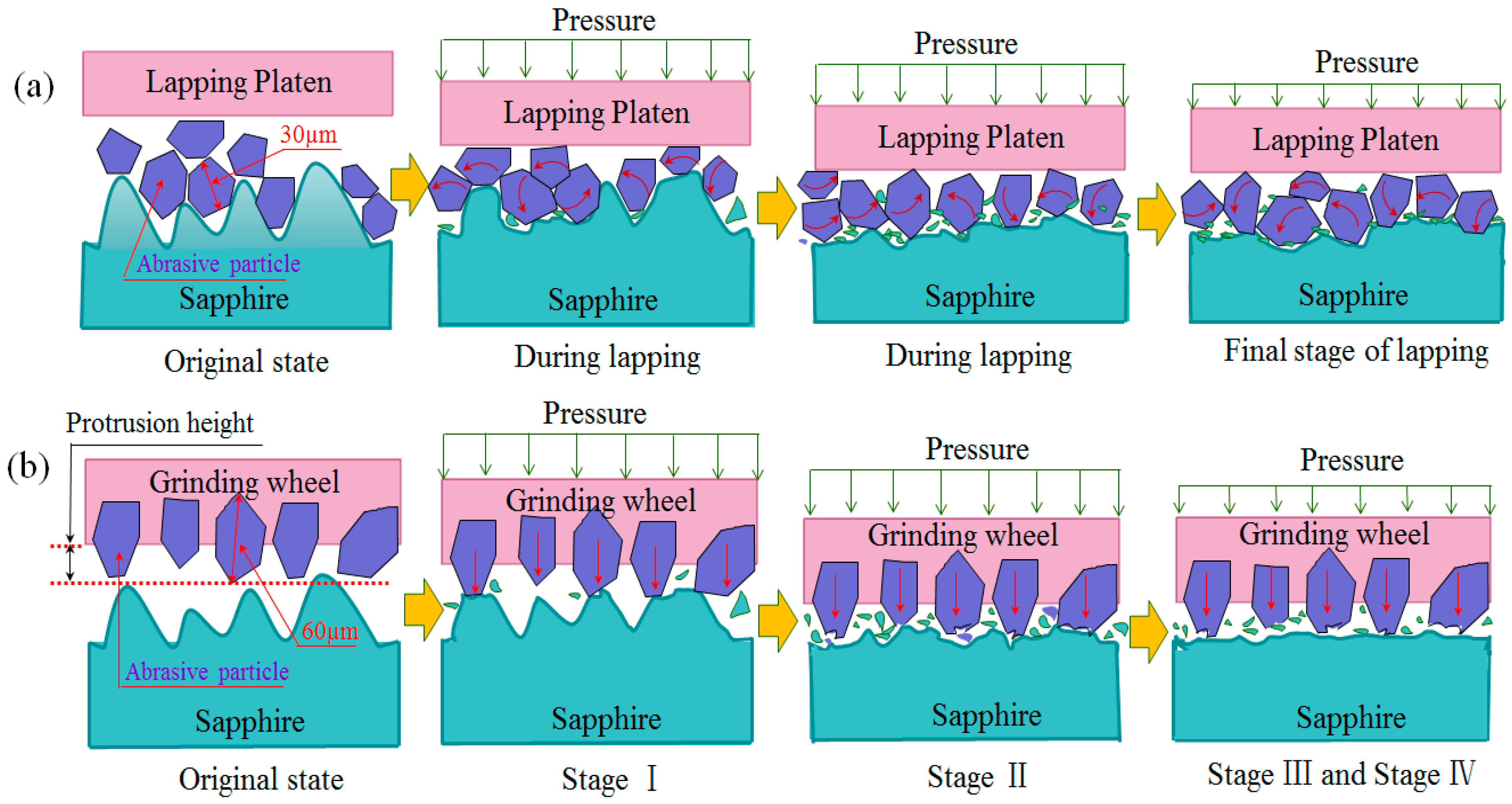
In order to further reveal the above experimental results, the proposed sapphire removal process using two models of lapping is schematically shown in Figure 14. Firstly, compared with current industry lapping removal rate of 3~4 µm/min, MRR of 10.0 µm/min is obtained in double-sided planetary grinding for the following reasons. 3-body and 2-body lapping system are defined to describe fixed abrasive lapping and free abrasive lapping, respectively, in previous literature [23]. According to literature [24], higher hardness platen obtained higher removal rate, and double-sided planetary grinding could be seen as 2-body lapping, in which high hardness platen is used. Most of the abrasives in free abrasive lapping roll between the substrate and the platen, which has minor effect on MRR. Regarding the abrasives that are embedded on the platen slide on the substrate, this abrasive sliding on substrate contributes mostly to removal rate. Almost all diamond abrasives on the grinding wheels are active abrasives; the larger number of active abrasive sliding on substrate leads to higher MRR. On the other hand, the diamond abrasives in free abrasive lapping remove not only substrates but also lapping platen; in contrast, diamond abrasives in double-sided planetary grinding have more chance of sliding on substrates. Secondly, compared with current industry Ra of about 800 nm, which is produced by free abrasives with sizes of approximate 30 µm, Ra of about 400 nm that is produced by fixed abrasives with size of approximate 60 µm is obtained in double-sided planetary grinding. In addition, shallow and dense dents on substrate surface are produced by double-sided planetary grinding. The main reasons are explained as follows. The protrusion height of diamond abrasives in double-sided planetary grinding obtains higher consistency than free abrasive lapping; this higher protrusion height consistency and the fixed location of the abrasives leads to uniform abrasive trajectories which, left on the substrate surface and the uniform abrasive trajectories, contribute mostly to surface uniformity of the substrates. Hence, not only low surface roughness but also shallow and dense dents on substrate surface are produced by double-sided planetary grinding. All of these have beneficial effects on the subsequent polishing process.
The results provide an experimental basis for the industrial application of double-sided planetary grinding on the rapid thinning and flattening of sapphire substrates. The experimental results can be used as reference for other materials of substrate, such as SiC and Si.
4. Conclusions
The use of a diamond grinding wheel, which could provide high hardness platen and fixed diamond abrasives, leads to high MRR and controllable surface quality of sapphire substrate in the process of preparation procedure. Double-sided planetary grinding with a ceramic bonded diamond wheel is suitable for the rapid thinning and flattening of the sapphire substrate. The main conclusions can be summarized as follows.
- (1)
- The grinding process is set into four stages, which can obtain a stable grinding process and improve the processing quality.
- (2)
- The good surface quality of the sapphire substrate (TTV ≤ 6 µm, Bow ≤ 2 µm, Warp ≤ 12 µm, Ra ≤ 390 nm) and high efficiency (MRR = 10.0 µm/min) can be achieved when grinding under the suitable rotational speed of the grinding wheel (120 rpm) and at a suitable grinding pressure (20.5 kPa).
- (3)
- The grinding of sapphire substrates shows an approximate linear dependence on the MRR with grinding pressure, the grinding wheel’s speed, and the grain size.
- (4)
- The larger size of the diamond grains (60 µm) could be used in double-sided planetary grinding to obtain higher processing efficiency with the promise of good surface quality.
Author Contributions
L.W. and Z.H. conceived and designed the experiments; L.W. performed the experiments and analyzed the data; and Y.Y. and X.X. made critical revisions to the article.
Funding
This work was supported by the National Natural Science Foundation of China (Grant Nos. 51575197 and 51675192) and Science and Technology Projects of Xiamen (Grant Nos. 3502Z20173047).
Conflicts of Interest
The authors declare no conflict of interest.
References
- Chen, W.C.; Tang, H.L. Research progress in light-emitting diode substrate materials. J. Phys. 2014, 63, 284–295. [Google Scholar]
- Yang, J.S.; Zhu, X.L.; Dong, Z.G.; Kang, R.K.; Guo, D.M.; Zhang, B. Design of Double-sided Polishing Machine for Functional Crystal Substrate. Adv. Mater. Res. 2014, 1017, 580–585. [Google Scholar] [CrossRef]
- Li, Z.C.; Pei, Z.J. Machining process for Sapphire Wafers: A Literature Review. Proc. Inst. Mech. Eng. Part B J. Eng. Manuf. 2011, 225, 975–989. [Google Scholar] [CrossRef]
- Pei, Z.J.; Fisher, G.R.; Strasbaugh, A. Fine Grinding of Silicon Wafer: Benefits and Technical Barriers; Society of Manufacturing Engineers: Dearborn, MI, USA, 2004; pp. 284–295. [Google Scholar]
- Pei, Z.J.; Strasbaugh, A. Fine grinding of silicon wafers. Int. J. Mach. Tools Manuf. 2001, 41, 659–672. [Google Scholar] [CrossRef]
- Pei, Z.J.; Strasbaugh, A. Fine grinding of silicon wafers: Designed experiments. Int. J. Mach. Tools Manuf. 2002, 42, 395–404. [Google Scholar] [CrossRef]
- Chidambaram, S.; Pei, Z.J.; Kassir, S. Fine grinding of silicon wafers: A mathematical model for the chuck shape. Int. J. Mach. Tools Manuf. 2003, 43, 739–746. [Google Scholar] [CrossRef]
- Sun, W.P.; Pei, Z.J.; Fisher, G.R. Fine grinding of silicon wafers: A mathematical model for the wafer shape. Int. J. Mach. Tools Manuf. 2004, 44, 707–716. [Google Scholar] [CrossRef]
- Sun, W.P.; Pei, Z.J.; Fisher, G.R. Fine grinding of silicon wafers: Machine configurations for spindle angle adjustments. Int. J. Mach. Tools Manuf. 2005, 45, 51–61. [Google Scholar] [CrossRef]
- Shaw, M.C. Principles of Abrasive Processing; Oxford University Press: New York, NY, USA, 2000; p. 201. [Google Scholar]
- Su, J.X.; Liu, X.L.; Liu, Z.X. Experiment on lapping 6H-SiC crystal substrate (0001) Si surface based on diamond particle. J. Manuf. Process. 2013, 15, 148–154. [Google Scholar]
- Fang, C.F.; Zhao, Z.X.; Lu, L.Y. Influence of fixed abrasive configuration on the polishing process of silicon substrates. Int. J. Adv. Manuf. Technol. 2016, 90, 50–61. [Google Scholar]
- Yuan, J.L.; Yao, W.F.; Zhao, P.; Lyu, B.H.; Chen, Z.X.; Zhong, M.P. Kinematics and trajectory of both cylindrical lapping process in planetary motion type. Int. J. Mach. Tools Manuf. 2015, 92, 60–71. [Google Scholar] [CrossRef]
- Lu, J.; Luo, Q.F.; Mao, X.Y.; Xu, X.P.; Wang, Y.H.; Guo, H. Fabrication of a resin-bonded ultra-fine diamond abrasive polishing tool by electrophoretic co-deposition for SiC processing. Precis. Eng. 2017, 47, 353–361. [Google Scholar] [CrossRef]
- Liu, J.H.; Yang, J.D. The study of lapping trace by graphic transform on double-side lapping through a planet mechanism. J. Changchun Univ. Sci. Technol. 2002, 25, 40–42. [Google Scholar]
- Ku, L.M.; Yan, Z.; Suo, S.; Chang, Q.; Zhou, Q. Mathematical modeling and analysis of double-sided polishing process for 300 mm silicon substrates. Microelectronics 2008, 3, 373–376. [Google Scholar]
- Jin, Y.F.; Li, W.; Hu, G.X.; Hu, X.Z. Motion analysis for double-sided polishing process and mathematical model establishing. J. Nanjing Univ. Aeronaut. Astronaut. 2005, 37, 86–89. [Google Scholar]
- Kondratenko, V.S. Grinding Tool and Composition for Its Producing. Russian Patent RU 2169657, 27 June 2001. [Google Scholar]
- Kondratenko, V.S. Method of Abrasive Machining of Workpiece. Russian Patents RU 2172235, 20 August 2001. [Google Scholar]
- Kondratenko, V.S. Grinding Tool. Russian Patents RU 2208511, 20 July 2003. [Google Scholar]
- Gagliardi, J.J.; Kim, D.; Sokol, J.J.; Zazzera, L.A.; Romero, V.D.; Atkinson, M.R.; Zhang, H. A Case for 2-body Material Removal in Prime LED Sapphire Substrate Lapping and Polishing. J. Manuf. Process. 2013, 15, 348–354. [Google Scholar] [CrossRef]
- Cho, B.J.; Kim, H.M.; Manivannan, R.; Moon, D.J.; Park, J.G. On the mechanism of material removal by fixed abrasive lapping of various glass substrates. Wear 2013, 302, 1334–1339. [Google Scholar] [CrossRef]
- Kim, H.M.; Park, G.H.; Seo, Y.G.; Moon, D.J.; Cho, B.J.; Park, J.G. Comparison between sapphire lapping processes using 2-body and 3-body modes as a function of diamond abrasive size. Wear 2015, 332–333, 794–799. [Google Scholar] [CrossRef]
- Kim, H.M.; Manivannan, R.; Moon, D.J.; Xiong, H.; Park, J.G. Evaluation of double sided lapping using a fixed abrasive pad for Sapphire substrates. Wear 2013, 302, 134–145. [Google Scholar] [CrossRef]
- Jiang, F.; Luan, X.S.; Wang, N.C.; Xu, X.P.; Lu, X.Z.; Wen, Q.L. Research on the dynamic mechanical properties of C-plane sapphire under impact loading. Ceram. Int. 2018, 44. [Google Scholar] [CrossRef]
- Wang, J.H.; Guo, B.; Zhao, Q.L.; Zhang, C.Y.; Zhang, Q.L.; Zhai, W.J. Evolution of material removal modes of sapphire under varied scratching. Ceram. Int. 2017, 43, 10353–10360. [Google Scholar] [CrossRef]
- Luo, Q.F.; Lu, J.; Xu, X.P.; Jiang, F. Removal mechanism of sapphire substrates (0001, 1120 and 1010) in mechanical planarization machining. Ceram. Int. 2017, 43, 16178–16184. [Google Scholar] [CrossRef]
- Wang, L.J.; Hu, Z.W.; Fang, C.F.; Yu, Y.; Xu, X. Study on the double-sided grinding of sapphire substrates with the trajectory method. Precis. Eng. 2018, 51, 308–318. [Google Scholar] [CrossRef]
Figure 1.
Double-sided planetary grinding machine.
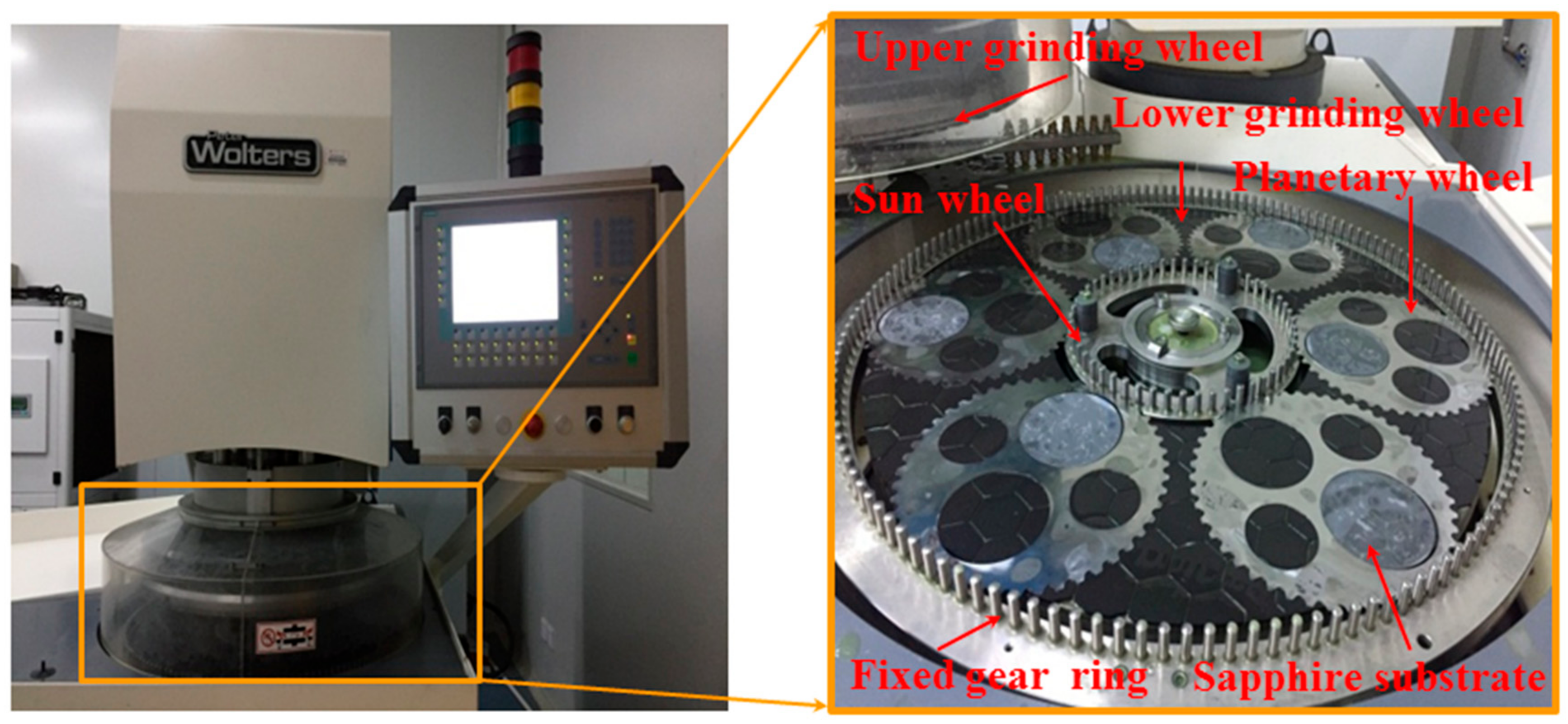
Figure 2.
The position of the testing areas: (a) the testing positions of surface roughness for each substrate and (b) testing areas of laser scanning confocal microscope.
Figure 2.
The position of the testing areas: (a) the testing positions of surface roughness for each substrate and (b) testing areas of laser scanning confocal microscope.
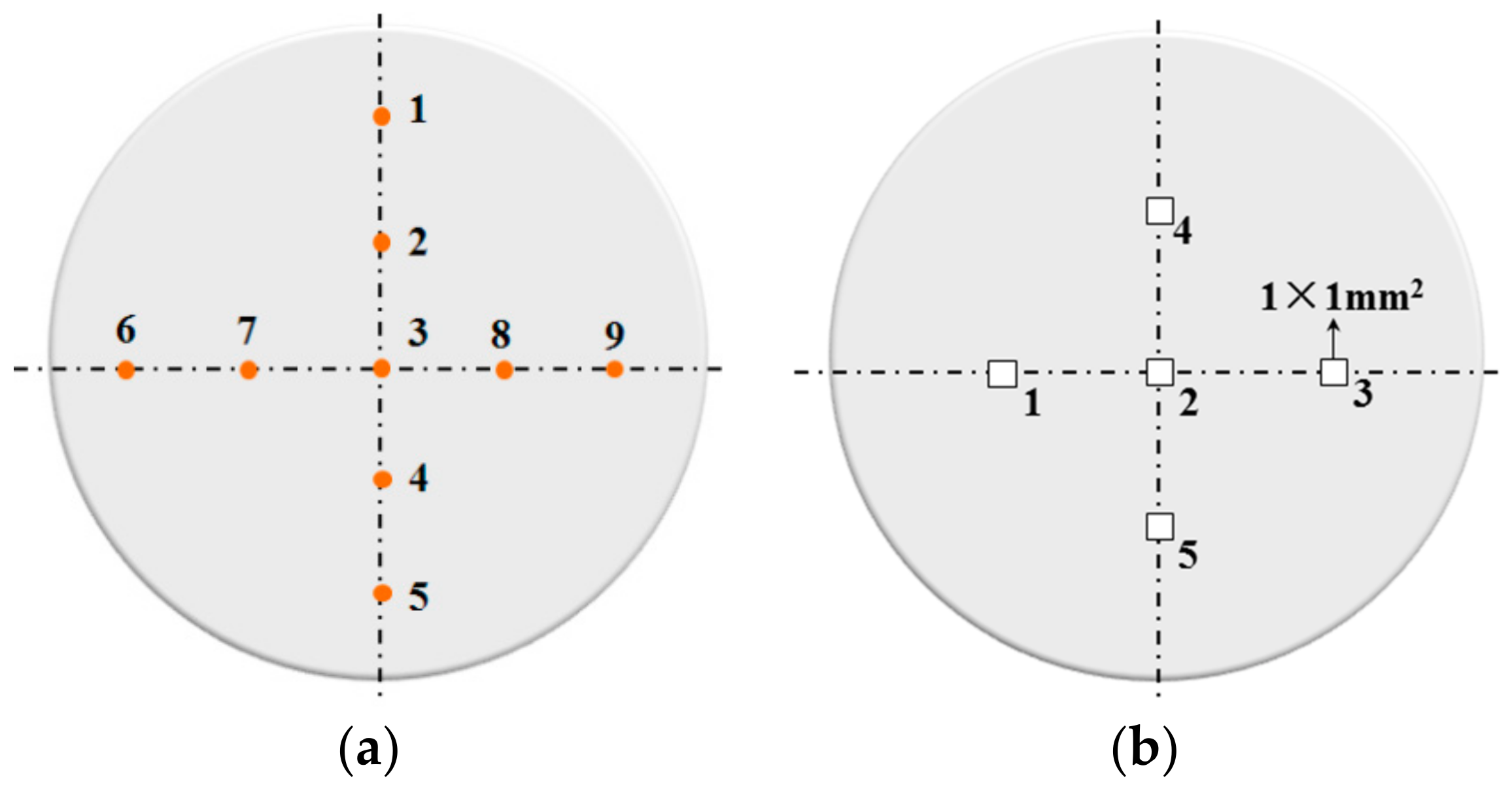
Figure 3.
The changing process of surface quality in four stages of grinding process: (a) Bow, (b) Warp, (c) TTV, and (d) Ra.
Figure 3.
The changing process of surface quality in four stages of grinding process: (a) Bow, (b) Warp, (c) TTV, and (d) Ra.

Figure 4.
The changing process of Bow and Warp in four stage of grinding process: (a) original state, (b) stage I, (c) stage II, (d) stage III, and (e) stage IV.
Figure 4.
The changing process of Bow and Warp in four stage of grinding process: (a) original state, (b) stage I, (c) stage II, (d) stage III, and (e) stage IV.
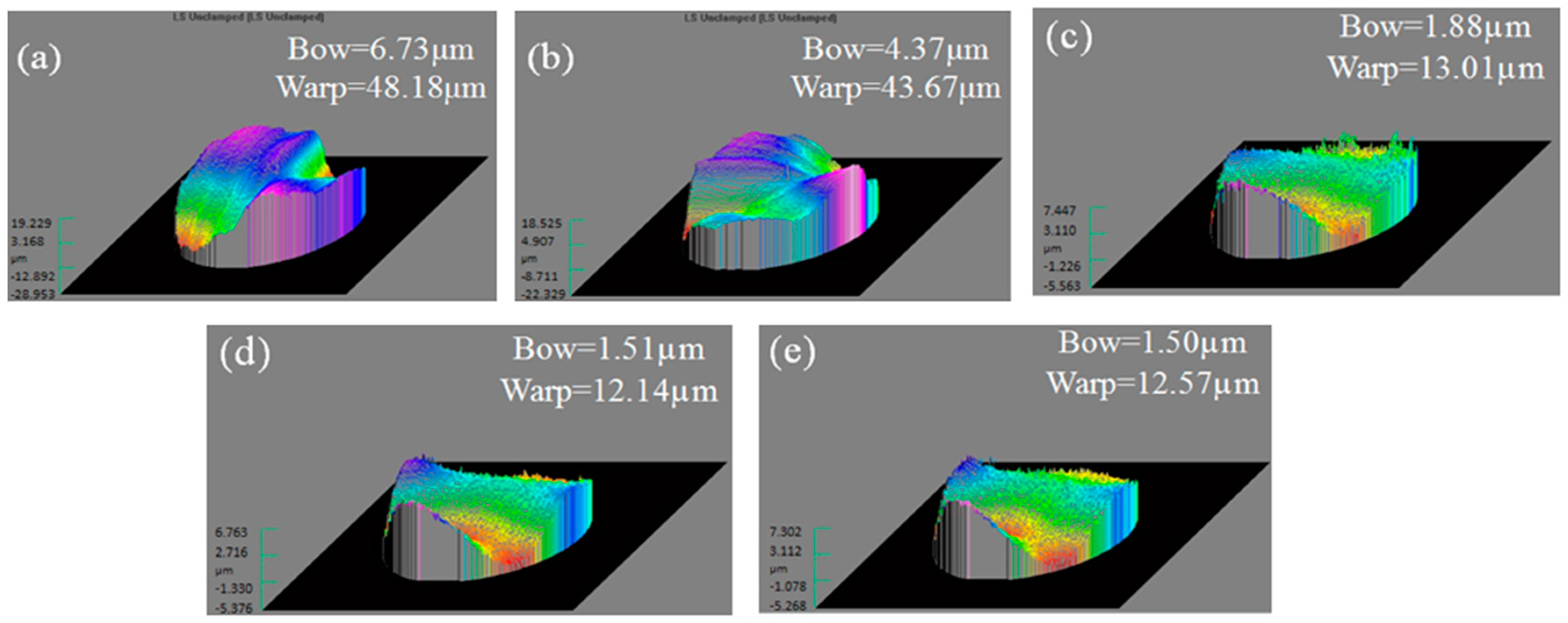
Figure 5.
The changing process of TTV in four stage of grinding process: (a) original state, (b) stage I, (c) stage II, (d) stage III, and (e) stage IV.
Figure 5.
The changing process of TTV in four stage of grinding process: (a) original state, (b) stage I, (c) stage II, (d) stage III, and (e) stage IV.

Figure 6.
Surface quality of sapphire substrates under the different rotation speeds of grinding wheels: (a) Bow, (b) Warp, (c) TTV, and (d) Ra.
Figure 6.
Surface quality of sapphire substrates under the different rotation speeds of grinding wheels: (a) Bow, (b) Warp, (c) TTV, and (d) Ra.
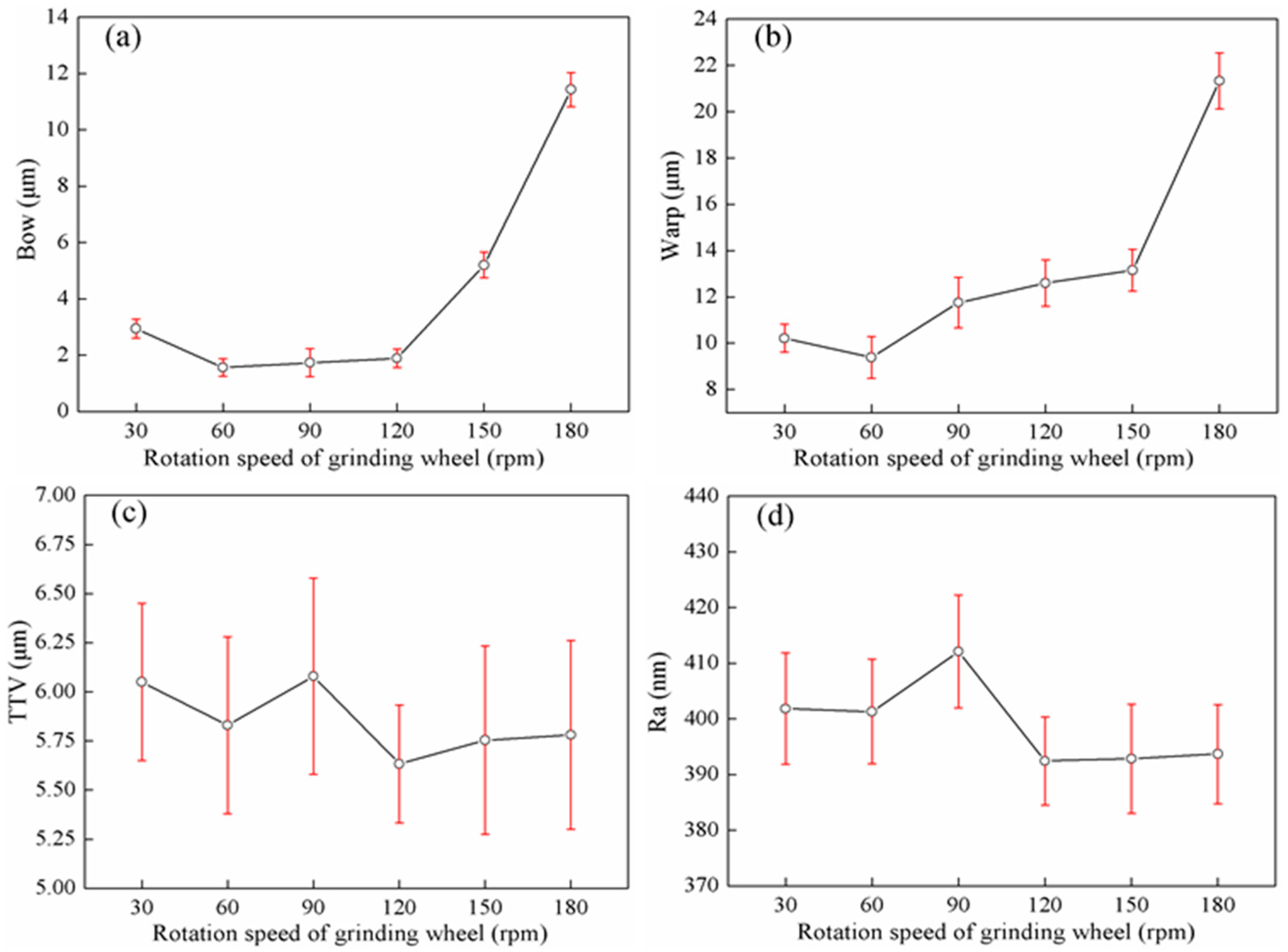
Figure 7.
MRR under the different rotation speeds of grinding wheel.

Figure 8.
Surface quality of sapphire substrates under the different grinding pressures: (a) Bow, (b) Warp, (c) TTV, and (d) Ra.
Figure 8.
Surface quality of sapphire substrates under the different grinding pressures: (a) Bow, (b) Warp, (c) TTV, and (d) Ra.

Figure 9.
MRR under the different grinding pressures.

Figure 10.
Surface quality of sapphire substrate under different grain size of grinding wheels: (a) Bow, (b) Warp, (c) TTV, and (d) Ra.
Figure 10.
Surface quality of sapphire substrate under different grain size of grinding wheels: (a) Bow, (b) Warp, (c) TTV, and (d) Ra.
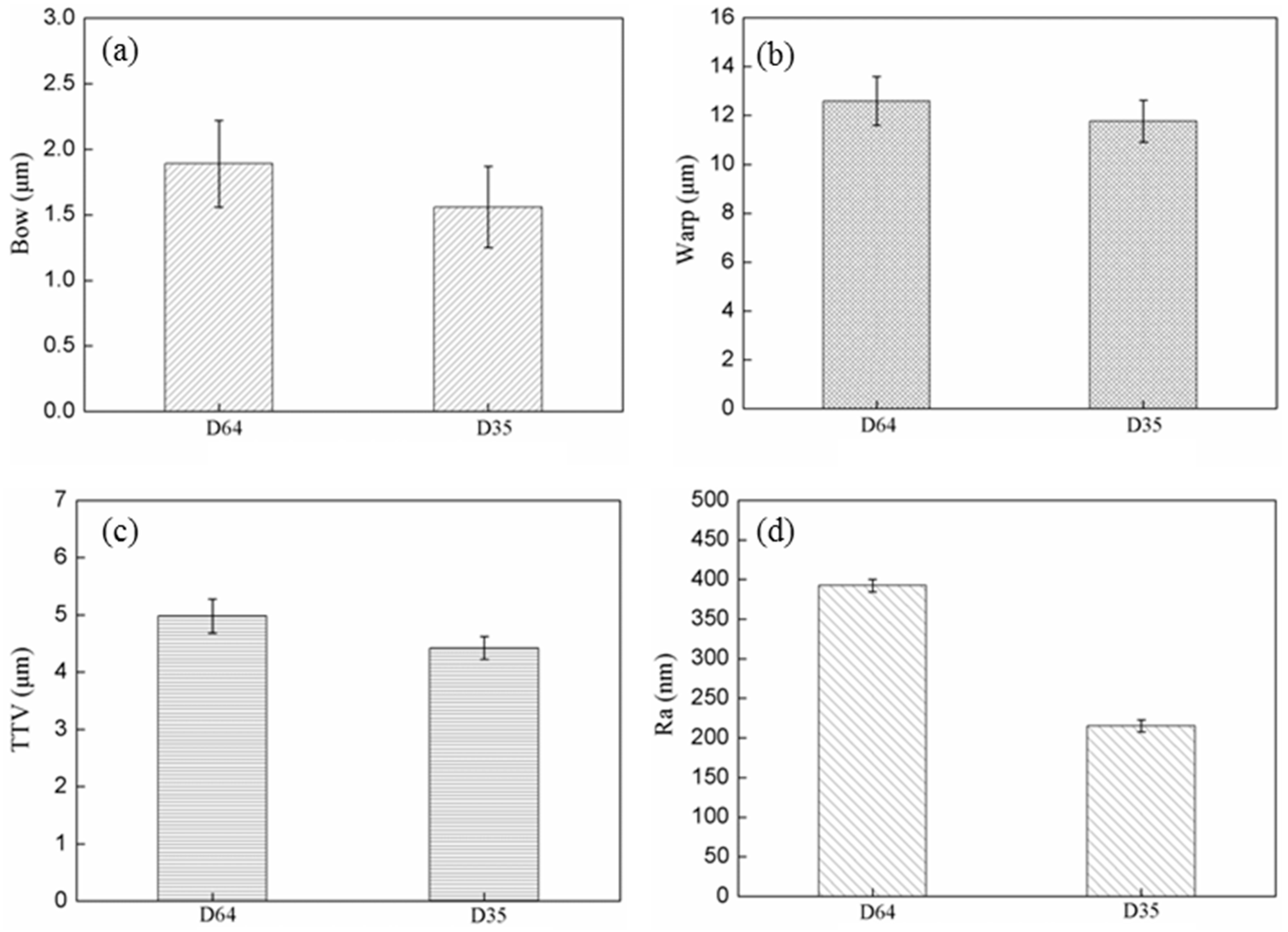
Figure 11.
MRR under different grain sizes of grinding wheels.

Figure 12.
The dent depth of sapphire surface that is produced by two lapping modes.

Figure 13.
The dent depth of sapphire surface that is produced by two lapping modes: (a) free abrasive lapping substrate, (b) double-sided planetary grinding substrate. Cross-sectional profile cut along (c) line A-A’ in (a); (d) line B-B’ in (b).
Figure 13.
The dent depth of sapphire surface that is produced by two lapping modes: (a) free abrasive lapping substrate, (b) double-sided planetary grinding substrate. Cross-sectional profile cut along (c) line A-A’ in (a); (d) line B-B’ in (b).
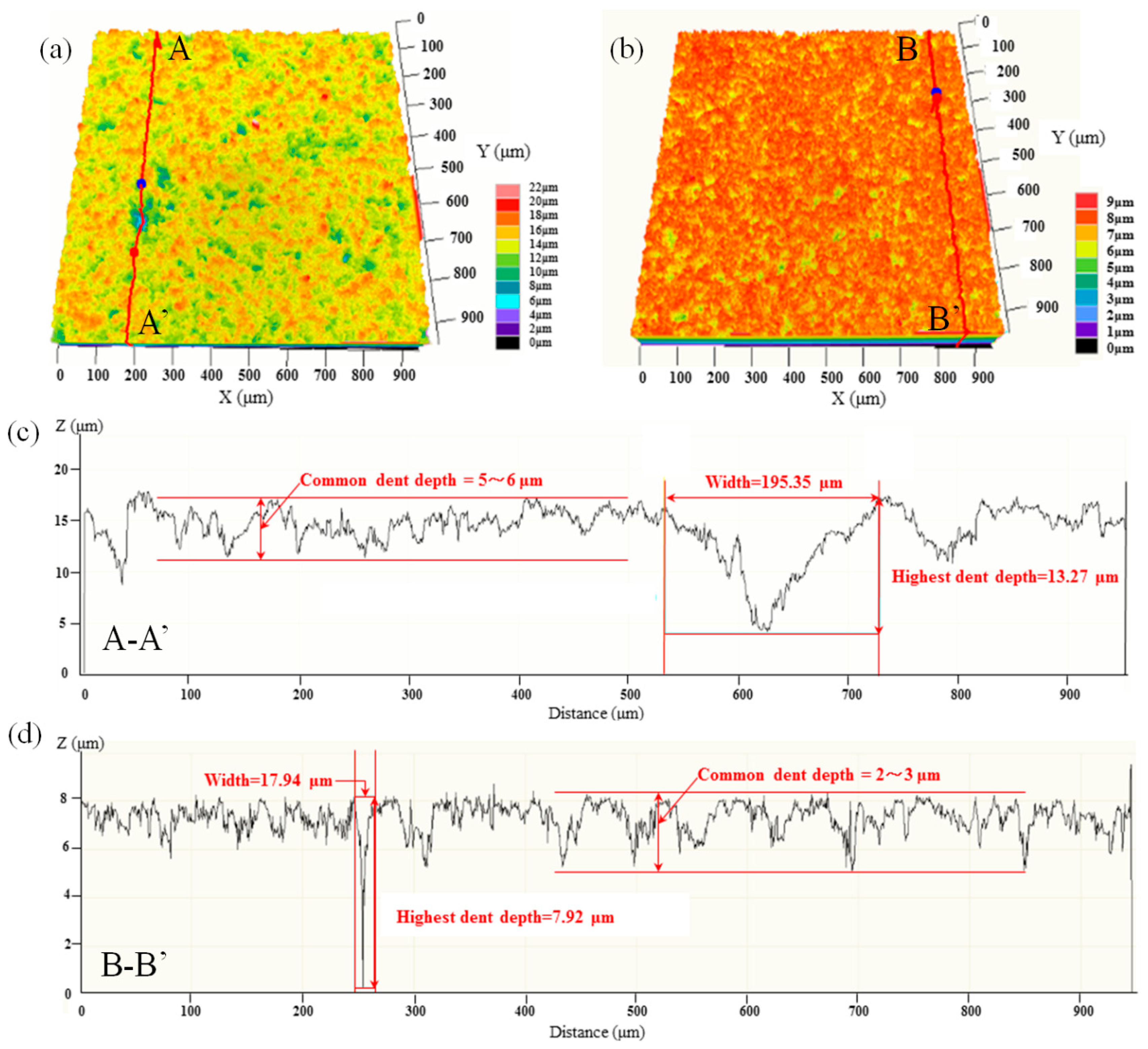
Figure 14.
Sapphire removal process using (a) free abrasive lapping and (b) double-sided planetary grinding.
Figure 14.
Sapphire removal process using (a) free abrasive lapping and (b) double-sided planetary grinding.

Table 1.
Experimental parameters of grinding process.
| Rotation Speed of Upper Grinding Wheel (rpm) | Rotation Speed of Lower Grinding Wheel (rpm) | Rotation Speed of the Sun Wheel (rpm) | Grinding Pressure (kPa) | Removal Thichness (µm) | Coolant Switch | |
|---|---|---|---|---|---|---|
| Stage I | 60 | −60 | 10 | 0~20.5 | 0 | on |
| Stage II | 90 | −90 | 10 | 20.5 | 70 | on |
| Stage III | 60 | −60 | 10 | 6.15 | 8 | on |
| Stage IV | 60 | −60 | 10 | 2.05 | 2 | off |
© 2018 by the authors. Licensee MDPI, Basel, Switzerland. This article is an open access article distributed under the terms and conditions of the Creative Commons Attribution (CC BY) license (http://creativecommons.org/licenses/by/4.0/).
Share and Cite
MDPI and ACS Style
Wang, L.; Hu, Z.; Yu, Y.; Xu, X. Evaluation of Double-Sided Planetary Grinding Using Diamond Wheels for Sapphire Substrates. Crystals 2018, 8, 262. https://doi.org/10.3390/cryst8070262
AMA Style
Wang L, Hu Z, Yu Y, Xu X. Evaluation of Double-Sided Planetary Grinding Using Diamond Wheels for Sapphire Substrates. Crystals. 2018; 8(7):262. https://doi.org/10.3390/cryst8070262
Chicago/Turabian StyleWang, Lijuan, Zhongwei Hu, Yiqing Yu, and Xipeng Xu. 2018. "Evaluation of Double-Sided Planetary Grinding Using Diamond Wheels for Sapphire Substrates" Crystals 8, no. 7: 262. https://doi.org/10.3390/cryst8070262
Note that from the first issue of 2016, this journal uses article numbers instead of page numbers. See further details here.