Bending Behavior of a Wrought Magnesium Alloy Investigated by the In Situ Pinhole Neutron Diffraction Method


Spallation Neutron Source, Oak Ridge National Laboratory, 1 Bethel Valley Rd, Oak Ridge, TN 37831, USA
*
Author to whom correspondence should be addressed.
Crystals 2018, 8(9), 348; https://doi.org/10.3390/cryst8090348
Submission received: 31 July 2018
/
Revised: 26 August 2018
/
Accepted: 27 August 2018
/
Published: 30 August 2018
(This article belongs to the Special Issue Neutron Diffractometers for Single Crystals and Powders)
Abstract
:The tensile twinning and detwinning behaviors of a wrought magnesium alloy have been investigated during in situ four-point bending using the state-of-the-art high spatial resolution pinhole neutron diffraction (PIND) method. The PIND method allowed us to resolve the tensile twinning/detwinning and lattice strain distributions across the bending sample during a loading-unloading sequence with a 0.5 mm step size. It was found that the extensive tensile twinning and detwinning occurred near the compression surface, while no tensile twinning behavior was observed in the middle layer and tension side of the bending sample. During the bending, the neutral plane shifted from the compression side to the tension side. Compared with the traditional neutron diffraction mapping method, the PIND method provides more detailed information inside the bending sample due to a higher spatial resolution.
1. Introduction
The deformation behavior of magnesium (Mg) alloys has been investigated extensively in the past decades, due to its combined excellent mechanical properties and lightweight [1,2]. The hexagonal close-packed (HCP) crystalline structure of Mg allows a limited number of slip systems, resulting in poor formability of wrought Mg alloys at room temperature, which restricts its wide applications. It has been well known that Mg possesses two easy deformation systems, {00.2}<11.0> basal <a> slip and {10.2}<10.1> tensile twinning (or extension twinning) [3,4,5,6]. The {10.2}<10.1> tensile twinning can be activated by tension parallel to the c-axis and compression perpendicular to the c-axis, which results in a sudden reorientation of the matrix lattice, approximately 86.3° [7,8]. The {10.2}<10.1> tensile twinning provides a tensile strain along the c-axis, which is not achievable by basal <a> slip [8,9]. The detwinning process can be activated by a stress/strain reversal in twined grains [10,11]. The majority of research has been focused on the deformation twinning behavior of Mg alloys under uniaxial loading conditions, such as tension, compression, and cyclic loading [12,13,14,15,16,17,18,19,20,21].
In automotive industries, the other deformation modes, i.e., plane strain and biaxial tension under linear and nonlinear strain paths, are very common during sheet metal forming. The plane strain deformation mode is critical for sheet metal forming since it has the lowest value on the forming limit curve [22]. In other words, the sheet metal is fractured at relatively smaller deformation strain levels compared with the other deformation modes, when it is subjected to the plane strain condition, such as pure bending [23,24]. In pure bending, there is a steep gradient of stress/strain distribution across the sample thickness and the deformation modes, such as twinning, can be complicated. However, research related to deformation twinning behaviors under pure bending conditions using in situ nondestructive methods is rare [25] in comparison to the aforementioned uniaxial deformation mode; in part due to the limitation of characterization tools capable of high spatial resolution. As twinning leads to a sharp change of crystallographic orientation, in-situ diffraction techniques such as X-rays and neutrons are often utilized for resolving the deformation behaviors.
The synchrotron high energy X-ray diffraction method provides the high spatial resolution, but the penetration depth is limited. On the other hand, neutrons provide a much deeper penetration and therefore their use is appropriate for various engineering materials studies [26,27,28,29,30,31,32,33,34,35,36,37,38,39,40,41,42,43,44,45,46,47]. However, the spatial resolution of conventional neutron diffraction measurements is not high enough, which is not applicable for the study of tensile twinning behavior during inhomogeneous deformation modes involving large strain gradients such as bending. Recently, at the VULCAN time-of-flight (TOF) engineering diffractometer [26], Spallation Neutron Source (SNS), Oak Ridge National Laboratory (ORNL), a pinhole neutron diffraction (PIND) non-destructive method was developed to improve the spatial resolution, close to 250 μm [48]. The potential scientific applications of the PIND method include deformation mechanism, phase transition, and grain orientation for the polycrystalline materials under load, temperature, and other external stimuli. It opens up a great opportunity for engineering applications in resolving materials mechanical response with a large gradient.
In the present research, we demonstrate a study on the deformation behavior of a wrought Mg alloy during four-point bending using the in situ high spatial resolution PIND method. The tensile twinning and detwinning behaviors during the four-point bending loading and unloading with a large strain gradient were spatially resolved with a 500 μm step size. The changes of intensity due to twinning, and lattice strain across the thickness upon loading and unloading are presented.
2. Experimental Methods
A commercial rolled AZ31B Mg alloy plate (chemical composition: 3 wt.% Al, 1 wt.% Zn and Mg as balance) in H24 temper (strain-hardened and partially annealed) was selected for the current research. A typical rolling texture with the HCP crystal c-axis parallel to the normal direction (ND) and perpendicular to the rolling direction (RD) has been analyzed in previous publications [13,14,15,16]. The four-point bending sample was machined using electrical discharge machining (EDM) with 60 mm in length (RD) × 15 mm in width [transverse direction (TD)] × 10 mm in thickness (ND). After sample machining, the four-point bending sample was annealed at 345 °C for 2 h to release the residual stress.
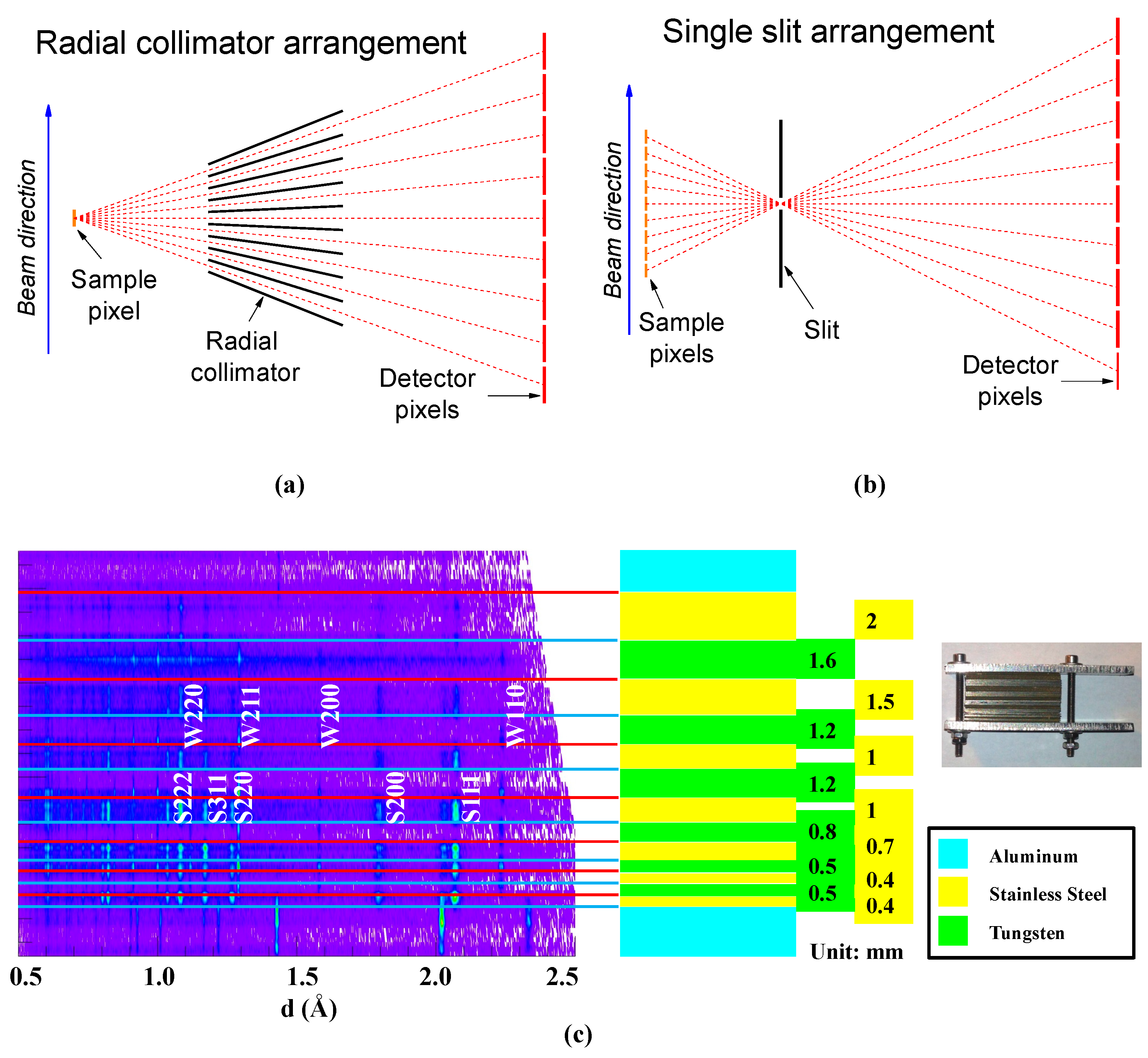
At VULCAN, diffraction patterns were collected at fixed scattering angles by measuring time-of-flight (TOF), the time interval between the neutron pulse generation and the detection moment, which is essentially proportional to the neutron wavelength. The sample was located far away from the neutron source (~42 m) to ensure a good TOF resolution (~0.2%). To preserve this good resolution in diffraction, the angular divergence in the incident and diffracted beam must be tightly controlled, at least in the diffraction plane. The neutron delivery system of VULCAN provides two optional levels of angular collimation: high resolution (HR) −0.2° by 1.6° (in the horizontal and vertical plane) and high intensity (HI) −0.6° by 1.6°. Diffracted beam divergence was determined by the extension of the sampling volume and detection area. Accordingly, large pixelated detectors were commonly used. A time focusing method [49] was utilized to convert the data recorded on large pixelated detector banks into a single polycrystalline pattern. At VULCAN, this procedure was facilitated by using event-based data reduction [50]. Considering the change in scattering angle, the scale of TOF values in each pixel was adjusted to align its diffraction pattern to the virtual center of the detector. Following that, a single set of diffraction constants were used to convert the TOF to lattice spacing value, d. This approach works well if the sample is small or the sampling volume is well defined. Currently, the sampling volume is defined by the incident beam slits (adjustable from 2 to 10 mm in both the horizontal and the vertical plane) and the radial collimators located between the specimen and the detector banks, restricting the field of view along the neutron beam path, as shown in Figure 1a. At VULCAN, the diffraction patterns were recorded by the two detector banks (B1 and B2), positioned at diffraction angles of ±90° with two convergent collimator options: 2 or 5 mm along the beam. Each bank includes three wavelength-shifting-fiber (WLSF) scintillator detectors [51], which have 154 by 7 pixels over a total area of 77 by 38 cm. The detector with a 5 mm horizontal pixel size ensured an average spatial resolution of ~5.5 mm full width at half maximum (FWHM), with a rather large spread across the detector [52]. The vertical dimension of a pixel is quite large (54.3 mm), but this condition does not affect the resolution in diffraction for take-off angles close to 90°. A cross-correlation calibration procedure using the diffraction patterns recorded in each detector pixel by a diamond powder sample generates the TOF shifts for time focusing. The instrument calibrations and data normalizations were performed by recording the diffraction pattern of a Si powder loaded in vanadium (V) and a V rod, measured in the same conditions as the studied samples.
The results reported in Reference [48] demonstrate the capability of the PIND method within a 2-D imaging arrangement, which used a 3He detector bank with similar pixilation in both the horizontal and vertical planes. Here, we demonstrate a one-dimensional application by using the WLSF detectors currently in use at VULCAN. The 1-D PIND concept is shown in Figure 1b. In this arrangement, the ‘pinhole’ was, in fact, a slit with a relaxed aperture in the vertical plane. In the horizontal plane, the slit was inserted between the sample and detector to create a link between a detector pixel and a location along the neutron beam crossing the sample. There was a constant ratio between the detector pixel size and the sample ‘virtual pixel’ size, which was determined by dividing slit-detector distance to sample-slit distance and named magnification factor (M). Indeed, the pinhole acts as a lens and small details on the sample are magnified at the detector by similarity. As such, the pinhole camera or ‘camera obscura’ was probably the first optical instrument [53], with a large field of view and a large depth of field. In light optics, the image resolution is limited by the light wave diffraction on the slit, which is proportional to the wavelength. For a pinhole neutron magnifying arrangement, the diffraction limit amounts to 10–15 μm at the detector, well below the pixel size. Thus, the geometrical optics were good enough to describe the point resolution. To estimate the error in the coordinate of the scattering event along the beam, , the uncertainty of the same coordinate at the pinhole location, , and at the detector location, , must be considered. Without considering the parallax effect, the variance of can be estimated as:
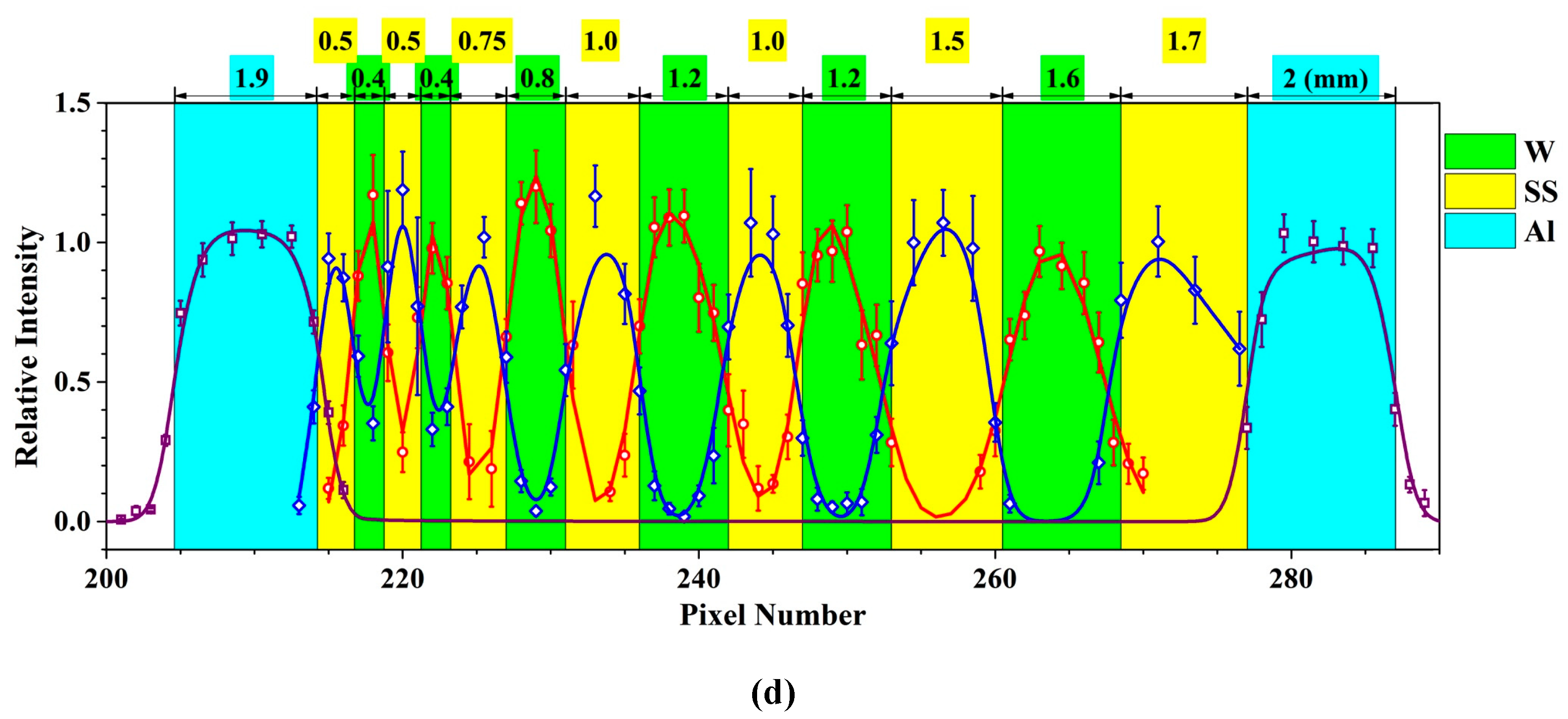
The experimental assessment of spatial resolution was performed by using a reference sample made by stacking foils of stainless steel and tungsten between two ticker plates of aluminum, as shown in Figure 1c. Different thicknesses of specific material layers were created by stacking certain numbers of consecutive foils of the same type. The layered sample was placed vertically with the foil’s surface perpendicular to the incident beam. A gadolinium slit, 0.5 mm wide, was placed 80 mm away from the specimen, in front of the detector bank located at 2000 mm from the sample position, resulting in a magnification factor of 24. For background reduction, the 5 mm radial collimator was retained in this arrangement and realigned to focus on the slit position. Since every pixel of the detector was utilized for the pinhole diffraction, TOF versus lattice spacing calibration of each pixel was conducted by measuring a diamond powder sample, which was moved along the beam direction to cover the entire field of view. The relative efficiency of each detector pixel was also evaluated and was later used for the diffraction peak intensity normalization. As shown in Figure 1c, the patterns from stainless steel, W and Al layers were separated both along d values (horizontal axis) as well as in real space (vertical axis). The Bragg peaks were separated due to their different lattice parameters, and the alternation of layers was resolved by the detector pixilation, which corresponded to 0.21 mm at the sample position. To evaluate the point resolution FWHM from experimental data, the spatial distribution of integral intensities of the first six diffraction peaks corresponding to stainless steel, W and Al has been fitted with a sum of Gaussians following the known sequence of foils as shown in Figure 1d. The thinnest layers (0.4–0.5 mm) gave a FWHM value of 0.54–0.55 mm. Subtracting the thickness of a single foil contribution, the instrument resolution was estimated to 0.43–0.47 mm FWHM, in agreement with the geometrical optics estimation of 0.42 mm, calculated by using Equation (1), with 5.5 mm FWHM as the detector resolution and 0.5 mm as the slit opening.
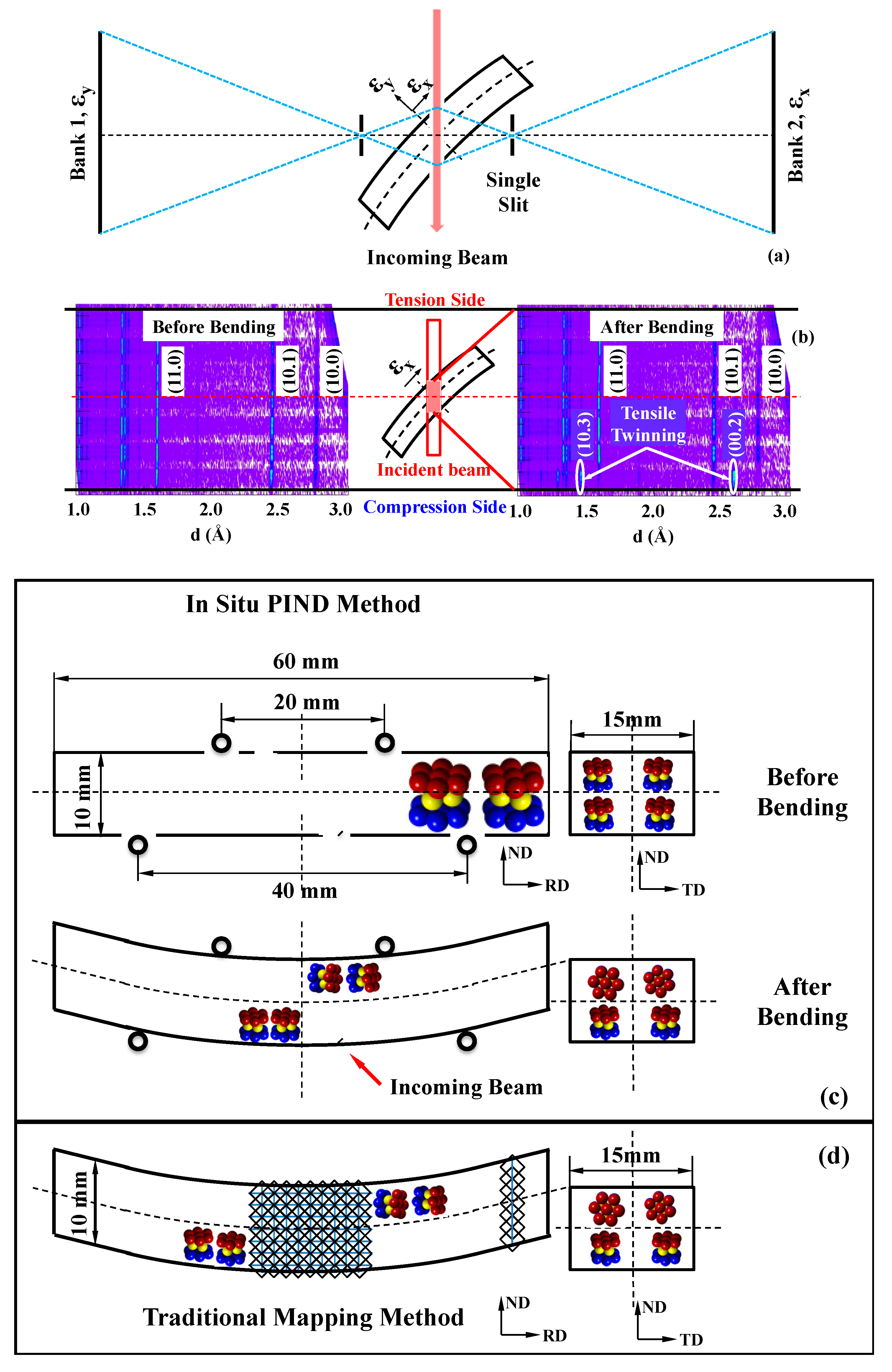
The schematics of in situ bending measurements using the PIND method are presented in Figure 2a. The Mg bending sample was located at 45° to the incoming neutron beam. The single Gadolinium slit, 1 mm wide, was positioned between the Mg bending sample and scintillator detector banks on each side. The distance between the Mg sample and the single Gadolinium slit was ~182 mm. As the total distance between the sample and the detector banks was 2000 mm, a magnification factor of ~10 was achieved, which means that the 5 mm wide detector pixel corresponded to a 0.5 mm step size at the sample position. In this PIND arrangement, the resolution along the beam was estimated to 0.9 mm FWHM. Across the neutron beam, the slit size was 1.5 mm (horizontal) × 12 mm (vertical).
The TOF diffractometers, as VULCAN, provided diffraction peak intensity and d-spacing (it can be used for the calculation of lattice strain) in different hkl crystal directions of grains in a polycrystalline sampling volume illuminated by the neutron beam. In the current experimental setup, detector banks 1 and 2 were probing the intensity diffracted by grains oriented with the hkl crystal direction along εy and εx sample directions, respectively, as shown in Figure 2a. The 2D diffraction patterns before and after bending tests are illustrated in Figure 2b (the purple white fluctuations were due to the background, and the regular dimmed intensities were due to the electronics efficiency of detector pixel bundles, which were normalized over a background measurement in the following intensity analysis). The top of the 2D diffraction pattern represents the tension side surface. From topside down, the diffraction patterns correlate to the various locations in the bending sample, which intersects with the incoming neutron beam. The bottom of the 2D diffraction pattern denotes the compression side surface.
The detailed schematics of the four-point bending experiment are demonstrated in Figure 2c. The distances between the inner and outer rollers were 20 and 40 mm, respectively. The schematics of lattice orientations before and after four-point bending are provided in Figure 2c. The incoming neutron beam direction is also indicated in Figure 2c. The in situ four-point bending experiment was performed at selected load levels, i.e., 0, −9000, −12,000, −15,000, and unloading to −100 N.
For comparison purposes, the bent sample was scanned using traditional neutron diffraction mapping method by moving the sample 1.4 mm per step across the bent area, as shown in Figure 2d. The neutron beam size was 2 mm (horizontal) × 10 mm (vertical). The 2 mm radial collimators were employed. The incoming neutron beam direction was the same as the PIND measurements. The reference intensity and lattice were measured from the undeformed region by averaging all 7 measurements, as indicated in Figure 2d.
By comparing the diffraction patterns before and after bending, it was noticed that the (00.2) and (10.3) peaks appeared on the compression side after bending; meanwhile, the (10.0) and (11.0) peaks disappeared. This behavior is characteristic for tensile twinning. On the tension surface side, the diffraction peak intensities of various hkls varied little; meaning no deformation twinning activities. The detailed description of tensile twinning behavior during in situ four-point bending experiments using the PIND method will be provided in the later sections. Moreover, in Figure 2b, it was noticed that the d-spacing of (11.0) grains moved toward the high d-spacing value gradually from the middle layer to the tension surface side after bending. This represented the residual lattice strain distribution across the sample. Therefore, from one measurement, the diffraction patterns across the bending sample were achieved by the PIND method, which provided grain orientation distribution at different locations, and diffraction peak intensity and lattice strain for each diffraction peak at each location.
3. Results and Discussion
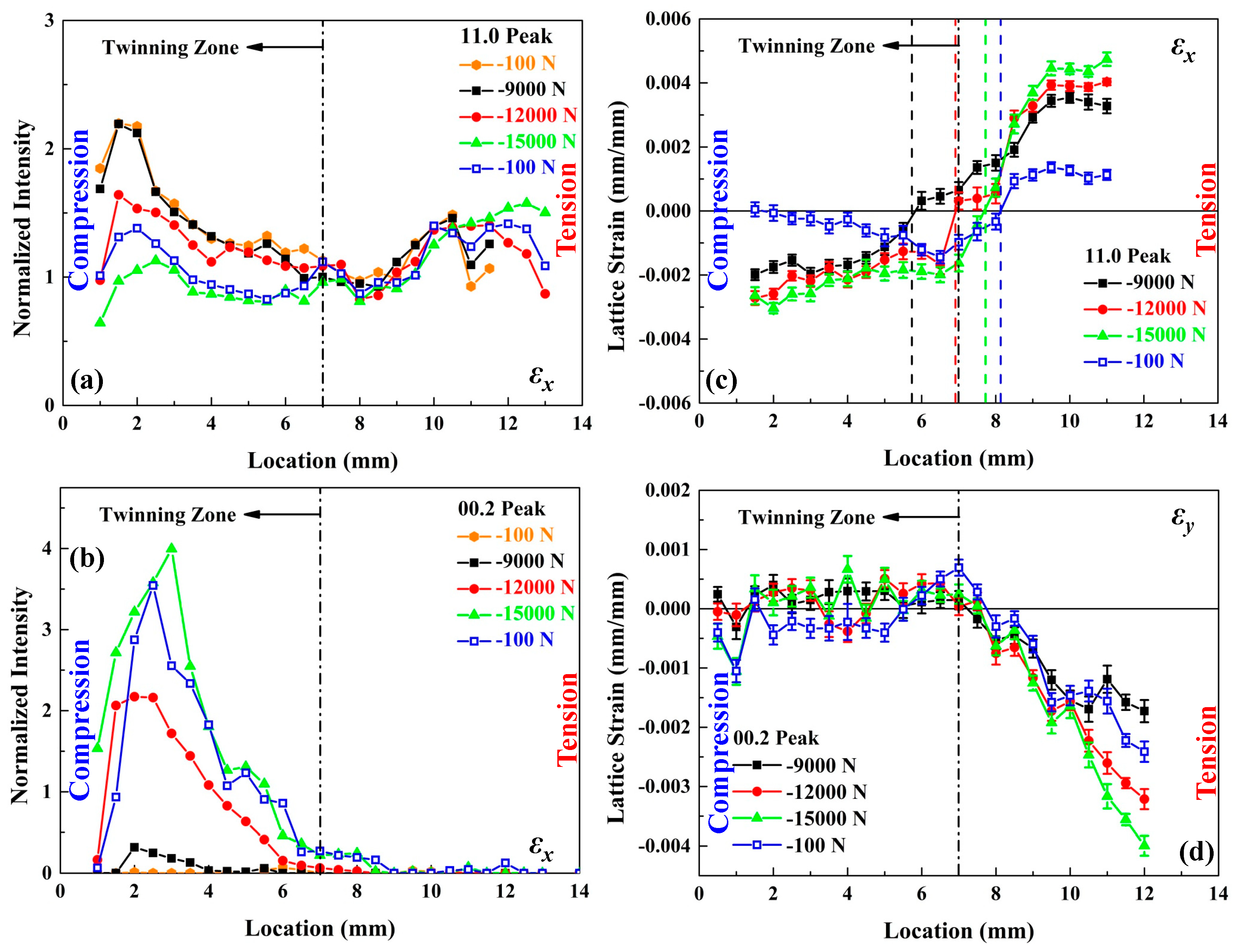
The (11.0) and (00.2) diffraction peak intensities in εx direction at different locations during the in situ four-point bending using PIND are exhibited in Figure 3a,b, respectively. The abscissa in Figure 3 and Figure 4 correspond to the 45° line of the bending sample, as marked in Figure 2c. On the compression side, it was observed in Figure 3a that the diffraction peak intensity of (11.0) grains remained the same when the applied load was below −9000 N. When the sample was further bent, up to −15,000 N, the diffraction peak intensity of (11.0) grains decreased at various locations from the compression surface to the middle layer, due to deformation by tensile twinning. The (11.0) peak intensity reduced steeply near the compression surface, since the compressive strain was much larger near the surface than the rest of the sample. The reduction of (11.0) peak intensity was gradually decreased when moving from the compression surface to the middle layer, due to the macroscopic strain gradient across the bent specimen. When the sample was unloaded to −100 N, a noticeable recovery of the diffraction peak intensity of (11.0) grains was observed near the compression surface, from 1 to 2.5 mm. This indicated that the detwinning occurred due to the back stress, as the local stress close to the surface evolved from compression to tension during unloading. On the tension side, the diffraction peak intensity of (11.0) grains remained almost unchanged during the four-point bending indicating that no deformation twinning occurred. The opposite trend can be found in diffraction peak intensity evolution of (00.2) grains in εx direction, as displayed in Figure 3b. The (00.2) peak intensity increased sharply when the applied bending force increased from −9000 to −15,000 N near the compression surface. It is interesting to note that the maximum diffraction peak intensity of (00.2) grains at −12,000 N appeared 2 mm below the compression surface. When the applied force was −15,000 N, the maximum diffraction peak intensity of (00.2) grains moved to 3 mm below the compression surface. This indicated that a large amount of tensile twinning occurred below the compression surface. When the sample was bent further, severe tensile twinning happened at a location further away from the compression surface, toward the middle layer, while the tensile twinning activities were decelerated and saturated near the compression surface. When the sample was unloaded to −100 N, the diffraction peak intensity of (00.2) grains decreased rapidly near the compression surface. From the change of the peak intensities, it can be concluded that almost all of the twinned grains were detwinned at the compression surface. On the other hand, from 3.5 mm to the middle layer, no detwinning was perceived. It is thought that large tensile stresses near compression surface, leading to severe detwinning, equilibrate after unloading the residual compressive stresses located closer to the middle layer. Nevertheless, from the in-situ high spatial resolution PIND measurements, it is confirmed that the twinning and detwinning occurred near the compression surface due to the large compressive strain enforced by bending and the change in the sign of stress at the surface due to unloading.
The lattice strain evolutions of (11.0) grains in εx direction and (00.2) grains in εy direction across the bending sample are illustrated in Figure 3c,d, respectively. In total, 4 load levels are selected, including −9000, −12,000, −15,000, and unloading to −100 N. As displayed in Figure 3c, a large lattice strain gradient was noticed across the sample during bending in the εx direction. The lattice strain of (11.0) grains increased slightly from 1 to 5 mm on the compression side from −9000 to −15,000 N. A similar trend was found from 8 to 11 mm on the tension side. It indicated that the lattice strains were saturated close to the compression and tension surface after the applied load reached −9000 N. On the other hand, the gradient of lattice strain in (11.0) grains varied significantly in the middle of the sample, when the bending force increased from −9000 to −15,000 N. Additionally, neutral plane shifting was observed during loading, which moved from the compression side to the tension side. The neutral planes at −9000, −12,000, −15,000 N are marked as black, red, and green dashed lines, respectively, in Figure 3c. It was also noted that the lattice strain levels on the compression surface side were much lower than the tension surface side at the selected load levels. This mainly results from the tension-compression in Mg, as the tensile twinning occurred on the compression side, while on the tension side the basal <a> slip and prismatic <a> slip deformation modes were dominant. The tensile twinning leads to an early yield and a limited strain hardening, but basal <a> slip and prismatic <a> slip results in a significant strain hardening behavior. After unloading, the residual lattice strains of (11.0) grains near compression surface, from 0 to 4 mm, were close to 0. It was gradually decreased to 6.5 mm, which reached the maximum compressive residual lattice strain at 6.5 mm, and then it started to increase progressively from 6.5 mm to 8 mm. From 8 mm to 8.5 mm, a sudden increase was perceived for the residual lattice strain of (11.0) grains, and it changed from the compressive to the tensile residual strain. It remained almost unchanged moving toward the tension surface. The neutral plane moved close to the tension surface after unloading, as marked as a blue dashed line in Figure 3c. In the εy direction, the lattice strain of (00.2) grains varied little during loading-unloading from 0.5 mm to 7 mm, in Figure 3d, while it decreased sharply from 7 mm to 12 mm. It was noted that at −9000 N, the lattice strain of (00.2) grains saturated from 10.5 mm to 12 mm, but it was linear when the sample was bent further. The relatively large lattice strain variations were observed from 10.5 mm to 12 mm during the loading. After the unloading, a small compressive residual lattice strain was notable from 0.5 mm to 5.5 mm. The tensile residual lattice strain was observed near the middle of the sample from 6 mm to 7.5 mm. The maximum residual tensile lattice strain of (00.2) grains was found at 7 mm, in the middle of the sample. Toward the tension side, the residual lattice strain of (00.2) grains decreased quickly. The largest compressive residual strain was found on the tension surface. Clearly, the lattice strain was distributed across the thickness and its evolutions at different load levels were revealed by the in-situ PIND measurements, which provided useful high-fidelity experimental validation for mechanics modeling and simulation of anisotropic materials deformation under bending.
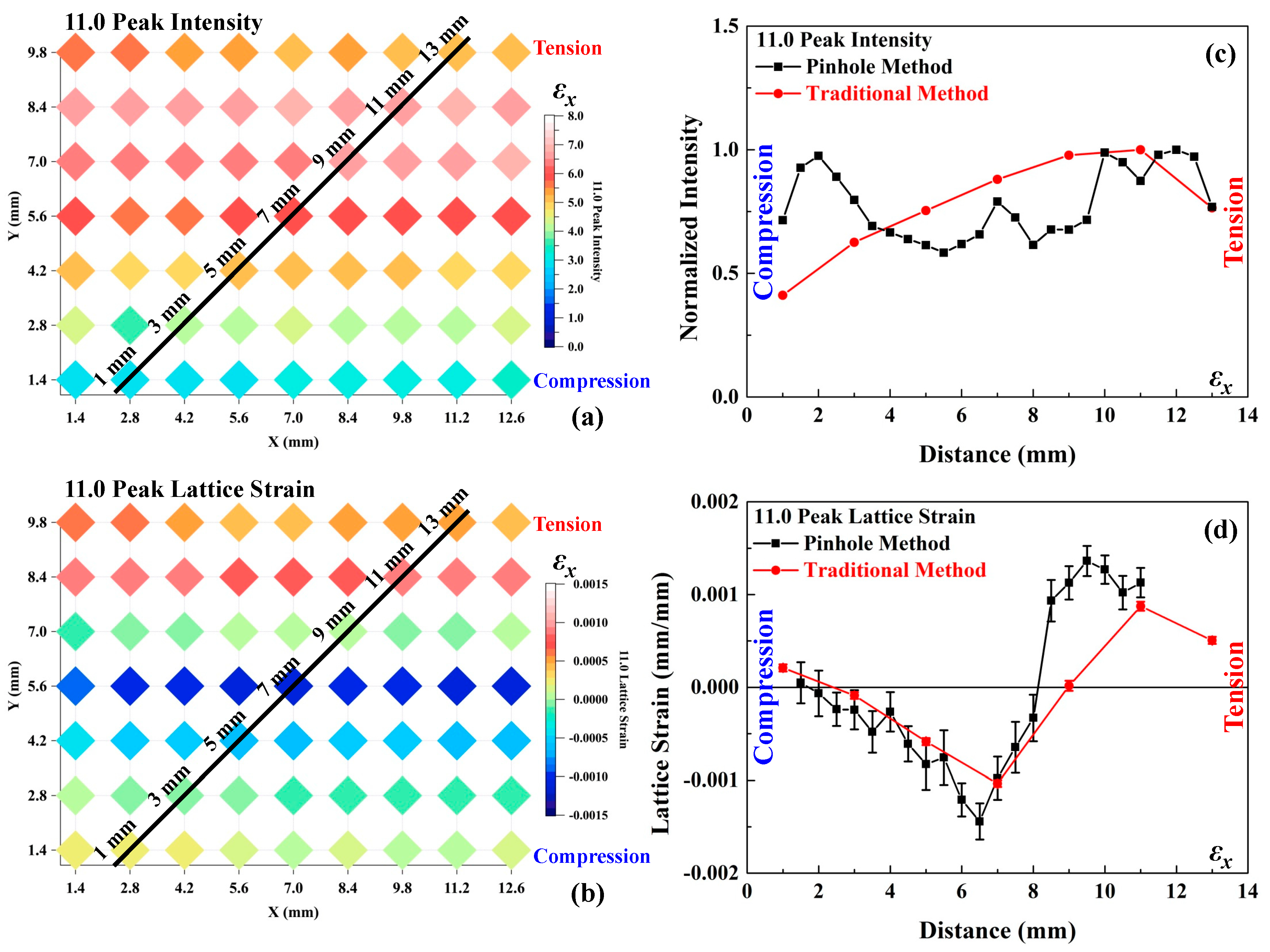
The PIND characterization shows great advantages over traditional measurement. The comparative traditional neutron diffraction mapping was performed on the bent sample to examine the diffraction peak intensity and residual lattice strain of (11.0) grains, as shown in Figure 4a,b, respectively, in the εx direction. The diffraction peak intensity of (11.0) grains on the compression side is much lower than the center and tension side, due to the tensile twinning and partial detwinning, as exhibited in Figure 4a. The maximum residual compressive and tensile lattice strains of (11.0) grains were witnessed in the middle layer and near the tension surface respectively. On the compression surface, a small amount of tensile residual lattice strain was perceived in Figure 4b. The diffraction peak intensity and lattice strain of (11.0) grains were retrieved along 45° from the traditional neutron diffraction mapping results, marked as a black solid line in Figure 4a,b, respectively, to compare with the results from the PIND method. The diffraction peak intensity and lattice strain of (11.0) grains measured by both methods are presented in Figure 4c,d, respectively. The general trend of diffraction peak intensity and lattice strain across the sample was similar from both methods. However, it is obvious that the results from the PIND method provide more details with higher spatial resolution over the traditional neutron diffraction mapping method, 0.5 mm vs. 2 mm.
4. Conclusions
The in situ high spatial resolution PIND method was employed in the present study to examine the tensile twinning and detwinning behavior during four-point bending and unloading under a large strain gradient. The severe tensile twinning and detwinning occurred near the compression surface during loading and unloading. Meanwhile, in the middle layer and near the tension surface side, no tensile twinning behavior was observed. The lattice strain saturated close to the compression and tension surface during bending, while a large lattice strain variation was observed across the middle layer. During the four-point bending experiment, the neutral plane moved from the compression to the tension side. The PIND method offered more detailed and rich information across the bending sample with much higher spatial resolution than the traditional neutron diffraction mapping method, which is extremely valuable to the materials science community.
Author Contributions
Conceptualization, A.D.S., K.A.; Methodology, A.D.S., K.A.; Formal Analysis, W.W., A.D.S., K.A.; Investigation, W.W., A.D.S., D.Y., M.J.F., H.D.S., K.A.; Writing-Orignial Draft Preparation, W.W.; Writing-Review & Editing, A.D.S, K.A; Supervision, K.A.; Funding Acquisition, A.D.S., K.A.
Funding
This research was funded by a Laboratory Directed Research and Development project (LDRD-6789) of ORNL.
Acknowledgments
This work was supported by a Laboratory Directed Research and Development project (LDRD-6789) of ORNL. This research used resources at the Spallation Neutron Source (SNS), Oak Ridge National Laboratory (ORNL), supported by the U.S. Department of Energy, Basic Energy Sciences, Scientific User Facilities Division. We thank Rick Allen for his engineering support. This manuscript has been authored by UT-Battelle, LLC under Contract No. DE-AC05-00OR22725 with the U.S. Department of Energy. The United States Government retains and the publisher, by accepting the article for publication, acknowledges that the United States Government retains a non-exclusive, paid-up, irrevocable, worldwide license to publish or reproduce the published form of this manuscript, or allow others to do so, for United States Government purposes. The Department of Energy will provide public access to these results of federally sponsored research in accordance with the DOE Public Access Plan (http://energy.gov/downloads/doe-public-access-plan).
Conflicts of Interest
The authors declare no conflicts of interest. The funders had no role in the design of the study; in the collection, analyses, or interpretation of data; in the writing of the manuscript, and in the decision to publish the results.
References
- Polmear, I.J. Magnesium alloys and applications. Mater. Sci. Technol. 1994, 10, 1–16. [Google Scholar] [CrossRef]
- Suh, B.C.; Shim, M.S.; Shin, K.S.; Kim, N.J. Current issues in magnesium sheet alloys: Where do we go from here? Scr. Mater. 2014, 84–85, 1–6. [Google Scholar] [CrossRef]
- Agnew, S.R.; Duygulu, O. Plastic anisotropy and the role of non-basal slip in magnesium alloy AZ31B. Int. J. Plast. 2005, 21, 1161–1193. [Google Scholar] [CrossRef]
- Lou, X.Y.; Li, M.; Boger, R.K.; Agnew, S.R.; Wagoner, R.H. Hardening evolution of AZ31B Mg sheet. Int. J. Plast. 2007, 23, 44–86. [Google Scholar] [CrossRef]
- Proust, G.; Tome, C.N.; Jain, A.; Agnew, S.R. Modeling the effect of twinning and detwinning during strain-path changes of magnesium alloy AZ31. Int. J. Plast. 2009, 25, 861–880. [Google Scholar] [CrossRef]
- Muransky, O.; Carr, D.G.; Sittner, P.; Oliver, E.C. In situ neutron diffraction investigation of deformation twinning and pseudoelastic-like behaviour of extruded AZ31 magnesium alloy. Int. J. Plast. 2009, 25, 1107–1127. [Google Scholar] [CrossRef]
- Wu, L.; Agnew, S.R.; Brown, D.W.; Stoica, G.M.; Clausen, B.; Jain, A.; Fielden, D.E.; Liaw, P.K. Internal stress relaxation and load redistribution during the twinning-detwinning-dominated cyclic deformation of a wrought magnesium alloy, ZK60A. Acta Mater. 2008, 56, 3699–3707. [Google Scholar] [CrossRef]
- Wu, L.; Jain, A.; Brown, D.W.; Stoica, G.M.; Agnew, S.R.; Clausen, B.; Fielden, D.E.; Liaw, P.K. Twinning-detwinning behavior during the strain-controlled low-cycle fatigue testing of a wrought magnesium alloy, ZK60A. Acta Mater. 2008, 56, 688–695. [Google Scholar] [CrossRef]
- Barnett, M.R. Twinning and the ductility of magnesium alloys Part I: “Tension” twins. Mater. Sci. Eng. A 2007, 464, 1–7. [Google Scholar] [CrossRef]
- Wu, W.; Chuang, C.-P.; Qiao, D.; Ren, Y.; An, K. Investigation of deformation twinning under complex stress states in a rolled magnesium alloy. J. Alloy. Comp. 2016, 683, 619–633. [Google Scholar] [CrossRef] [Green Version]
- Wu, W.; Gao, Y.; Li, N.; Parish, C.M.; Liu, W.; Liaw, P.K.; An, K. Intragranular twinning, detwinning, and twinning-like lattice reorientation in magnesium alloys. Acta Mater. 2016, 121, 15–23. [Google Scholar] [CrossRef] [Green Version]
- Wu, W.; Lee, S.Y.; Paradowska, A.M.; Gao, Y.F.; Liaw, P.K. Twinning-detwinning behavior during fatigue-crack propagation in a wrought magnesium alloy AZ31B. Mater. Sci. Eng. A 2012, 556, 278–286. [Google Scholar] [CrossRef]
- Wu, W.; An, K.; Huang, L.; Lee, S.Y.; Liaw, P.K. Deformation dynamics study of a wrought magnesium alloy by real-time in situ neutron diffraction. Scr. Mater. 2013, 69, 358–361. [Google Scholar] [CrossRef]
- Wu, W.; Qiao, H.; An, K.; Guo, X.Q.; Wu, P.D.; Liaw, P.K. Investigation of deformation dynamics in a wrought magnesium alloy. Int. J. Plast. 2014, 62, 105–120. [Google Scholar] [CrossRef]
- Wu, W.; Liaw, P.K.; An, K. Unraveling cyclic deformation mechanisms of a rolled magnesium alloy using in situ neutron diffraction. Acta Mater. 2015, 85, 343–353. [Google Scholar] [CrossRef] [Green Version]
- Wu, W.; An, K. Understanding low-cycle fatigue life improvement mechanisms in a pre-twinned magnesium alloy. J. Alloy. Comp. 2016, 656, 539–550. [Google Scholar] [CrossRef]
- Agnew, S.R.; Mulay, R.P.; Polesak, F.J.; Calhoun, C.A.; Bhattacharyya, J.J.; Clausen, B. In situ neutron diffraction and polycrystal plasticity modeling of a Mg-Y-Nd-Zr alloy: Effects of precipitation on individual deformation mechanisms. Acta Mater. 2013, 61, 3769–3780. [Google Scholar] [CrossRef]
- Brown, D.W.; Agnew, S.R.; Bourke, M.A.M.; Holden, T.M.; Vogel, S.C.; Tome, C.N. Internal strain and texture evolution during deformation twinning in magnesium. Mater. Sci. Eng. A 2005, 399, 1–12. [Google Scholar] [CrossRef]
- Brown, D.W.; Jain, A.; Agnew, S.R.; Clausen, B. Twinning and detwinning during cyclic deformation of Mg alloy AZ31B. In Materials Science Forum; Chandra, T., Tsuzaki, K., Militzer, M., Ravindran, C., Eds.; Trans Tech Publications: Stafa-Zurich, Switzerland, 2007; Volume 539, pp. 3407–3413. [Google Scholar]
- Wu, L.; Agnew, S.R.; Ren, Y.; Brown, D.W.; Clausen, B.; Stoica, G.M.; Wenk, H.R.; Liaw, P.K. The effects of texture and extension twinning on the low-cycle fatigue behavior of a rolled magnesium alloy, AZ31B. Mater. Sci. Eng. A 2010, 527, 7057–7067. [Google Scholar] [CrossRef]
- Lee, S.Y.; Wang, H.; Gharghouri, M.A.; Nayyeri, G.; Woo, W.; Shin, E.; Wu, P.D.; Poole, W.J.; Wu, W.; An, K. Deformation behavior of solid-solution-strengthened Mg-9 wt% Al alloy: In situ neutron diffraction and elastic-viscoplastic self-consistent modeling. Acta Mater. 2014, 73, 139–148. [Google Scholar] [CrossRef]
- Huang, G.-S.; Zhang, H.; Gao, X.-Y.; Song, B.; Zhang, L. Forming limit of textured AZ31B magnesium alloy sheet at different temperatures. Trans. Nonferr. Met. Soc. China 2011, 21, 836–843. [Google Scholar] [CrossRef]
- Habibnejad-korayem, M.; Jain, M.K.; Mishra, R.K. Large deformation of magnesium sheet at room temperature by preform annealing, part II: “Bending”. Mater. Sci. Eng. A 2014, 619, 378–383. [Google Scholar] [CrossRef]
- Aslam, I.; Li, B.; McClelland, Z.; Horstemeyer, S.J.; Ma, Q.; Wang, P.T.; Horstemeyer, M.F. Three-point bending behavior of a ZEK100 Mg alloy at room temperature. Mater. Sci. Eng. A 2014, 590, 168–173. [Google Scholar] [CrossRef]
- Jin, L.; Dong, J.; Sun, J.; Luo, A.A. In-situ investigation on the microstructure evolution and plasticity of two magnesium alloys during three-point bending. Int. J. Plast. 2015, 72, 218–232. [Google Scholar] [CrossRef]
- An, K.; Skorpenske, H.D.; Stoica, A.D.; Ma, D.; Wang, X.L.; Cakmak, E. First In Situ Lattice Strains Measurements Under Load at VULCAN. Metall. Mater. Trans. A 2011, 42a, 95–99. [Google Scholar] [CrossRef]
- Sun, Y.; An, K.; Tang, F.; Hubbard, C.R.; Lu, Y.L.; Choo, H.; Liaw, P.K. Changes in lattice-strain profiles around a fatigue crack through the retardation period after overloading. Physica B 2006, 385, 633–635. [Google Scholar] [CrossRef]
- Woo, W.; Feng, Z.L.; Wang, X.L.; An, K.; Hubbard, C.R.; David, S.A.; Choo, H. In situ neutron diffraction measurement of transient temperature and stress fields in a thin plate. Appl. Phys. Lett. 2006, 88, 261903. [Google Scholar] [CrossRef]
- Woo, W.; Feng, Z.; Wang, X.L.; Brown, D.W.; An, B.K.; Choo, H.; Hubbard, C.R.; David, S.A. In situ neutron diffraction measurements of temperature and stresses during friction stir welding of 6061-T6 aluminium alloy. Sci. Technol. Weld. Joi. 2007, 12, 298–303. [Google Scholar] [CrossRef]
- Lee, S.Y.; Sun, Y.; An, K.; Choo, H.; Hubbard, C.R.; Liaw, P.K. Evolution of residual-strain distribution through an overload-induced retardation period during fatigue-crack growth. J. Appl. Phys. 2010, 107, 023517. [Google Scholar] [CrossRef]
- Benafan, O.; Noebe, R.D.; Padula, S.A., II; Gaydosh, D.J.; Lerch, B.A.; Garg, A.; Bigelow, G.S.; An, K.; Vaidyanathan, R. Temperature-dependent behavior of a polycrystalline NiTi shape memory alloy around the transformation regime. Scr. Mater. 2013, 68, 571–574. [Google Scholar] [CrossRef]
- Watkins, T.; Bilheux, H.; An, K.; Payzant, A.; Dehoff, R.; Duty, C.; Peter, W.; Blue, C.; Brice, C. Neutron characterization for additive manufacturing. Adv. Mater. Process 2013, 171, 23–27. [Google Scholar]
- Yu, D.; An, K.; Chen, Y.; Chen, X. Revealing the cyclic hardening mechanism of an austenitic stainless steel by real-time in situ neutron diffraction. Scr. Mater. 2014, 89, 45–48. [Google Scholar] [CrossRef]
- Yu, D.; Bei, H.; Chen, Y.; George, E.P.; An, K. Phase-specific deformation behavior of a relatively tough NiAl-Cr(Mo) lamellar composite. Scr. Mater. 2014, 84–85, 59–62. [Google Scholar] [CrossRef]
- Huang, E.W.; Yu, D.J.; Yeh, J.W.; Lee, C.; An, K.; Tu, S.Y. A study of lattice elasticity from low entropy metals to medium and high entropy alloys. Scr. Mater. 2015, 101, 32–35. [Google Scholar] [CrossRef] [Green Version]
- Huang, S.Y.; Gao, Y.F.; An, K.; Zheng, L.L.; Wu, W.; Teng, Z.K.; Liaw, P.K. Deformation mechanisms in a precipitation-strengthened ferritic superalloy revealed by in situ neutron diffraction studies at elevated temperatures. Acta Mater. 2015, 83, 137–148. [Google Scholar] [CrossRef] [Green Version]
- Cakmak, E.; Kirka, M.M.; Watkins, T.R.; Cooper, R.C.; An, K.; Choo, H.; Wu, W.; Dehoff, R.R.; Babu, S.S. Microstructural and micromechanical characterization of IN718 theta shaped specimens built with electron beam melting. Acta Mater. 2016, 108, 161–175. [Google Scholar] [CrossRef] [Green Version]
- Yu, D.J.; An, K.; Chen, X.; Bei, H.B. Phase-specific deformation behavior of a NiAl-Cr(Mo) lamellar composite under thermal and mechanical loads. J. Alloy. Compd. 2016, 656, 481–490. [Google Scholar] [CrossRef]
- An, K.; Yuan, L.; Dial, L.; Spinelli, I.; Stoica, A.D.; Gao, Y. Neutron residual stress measurement and numerical modeling in a curved thin-walled structure by laser powder bed fusion additive manufacturing. Mater. Des. 2017, 135, 122–132. [Google Scholar] [CrossRef]
- Benafan, O.; Garg, A.; Noebe, R.D.; Skorpenske, H.D.; An, K.; Schell, N. Deformation characteristics of the intermetallic alloy 60NiTi. Intermetallics 2017, 82, 40–52. [Google Scholar] [CrossRef]
- Liu, T.K.; Wu, Z.; Stoica, A.D.; Xie, Q.; Wu, W.; Gao, Y.F.; Bei, H.; An, K. Twinning-mediated work hardening and texture evolution in CrCoFeMnNi high entropy alloys at cryogenic temperature. Mater. Des. 2017, 131, 419–427. [Google Scholar] [CrossRef]
- Xie, Q.; Chen, Y.; Yang, P.; Zhao, Z.; Wang, Y.D.; An, K. In-situ neutron diffraction investigation on twinning/detwinning activities during tension-compression load reversal in a twinning induced plasticity steel. Scr. Mater. 2018, 150, 168–172. [Google Scholar] [CrossRef]
- Xie, Q.; Liang, J.; Stoica, A.D.; Li, R.; Yang, P.; Zhao, Z.; Wang, J.; Lan, H.; Li, R.; An, K. In-situ neutron diffraction study on the tension-compression fatigue behavior of a twinning induced plasticity steel. Scr. Mater. 2017, 137, 83–87. [Google Scholar] [CrossRef]
- Wang, D.M.; Chen, Y.; Mu, J.; Zhu, Z.W.; Zhang, H.F.; Wang, Y.D.; An, K. An in situ neutron diffraction study of plastic deformation in Cu46.5Zr46.5Al7 bulk metallic glass composite. Scr. Mater. 2018, 153, 118–121. [Google Scholar] [CrossRef]
- Wang, D.M.; Mu, J.; Chen, Y.; Qi, Y.M.; Wu, W.; Wang, Y.D.; Xu, H.J.; Zhang, H.F.; An, K. A study of stress-induced phase transformation and micromechanical behavior of CuZr-based alloy by in-situ neutron diffraction. J. Alloy. Compd. 2017, 696, 1096–1104. [Google Scholar] [CrossRef]
- Stoica, G.M.; Stoica, A.D.; Miller, M.K.; Ma, D. Temperature-dependent elastic anisotropy and mesoscale deformation in a nanostructured ferritic alloy. Nat. Commun. 2014, 5, 5178. [Google Scholar] [CrossRef] [PubMed] [Green Version]
- Wang, Z.Q.; Denlinger, E.; Michaleris, P.; Stoica, A.D.; Ma, D.; Beese, A.M. Residual stress mapping in Inconel 625 fabricated through additive manufacturing: Method for neutron diffraction measurements to validate thermomechanical model predictions. Mater. Des. 2017, 113, 169–177. [Google Scholar] [CrossRef]
- Wu, W.; Stoica, A.D.; Berry, K.D.; Frost, M.J.; Skorpenske, H.D.; An, K. PIND: High spatial resolution by pinhole neutron diffraction. Appl. Phys. Lett. 2018, 112, 253501. [Google Scholar] [CrossRef]
- Jorgensen, J.D.; Faber, J., Jr.; Carpenter, J.M.; Crawford, R.K.; Haumann, J.R.; Hitterman, R.L.; Kleb, R.; Ostrowski, G.E.; Rotella, F.J.; Worlton, T.G. Electronically focused time-of-flight powder diffractometers at the intense pulsed neutron source. J. Appl. Cryst. 1989, 22, 321–333. [Google Scholar] [CrossRef] [Green Version]
- Granroth, G.E.; An, K.; Smith, H.L.; Whitfield, P.; Neuefeind, J.C.; Lee, J.; Zhou, W.; Sedov, V.N.; Peterson, P.F.; Parizzi, A.; et al. Event-based processing of neutron scattering data at the Spallation Neutron Source. J. Appl. Cryst. 2018, 51, 616–629. [Google Scholar] [CrossRef]
- Wang, C.L.; Clonts, L.G.; Diawara, Y.; Hannan, B.W.; Hodges, J.P. Elimination of ghosting artifacts from wavelength-shifting-fiber neutron detectors. Rev. Sci. Instrum. 2013, 84, 013308. [Google Scholar] [CrossRef] [PubMed]
- Wang, C.L.; Riedel, R.A. Uniformity measurements and new positioning algorithms for wavelength-shifting-fiber neutron detectors. Nucl. Instrum. Meth. A 2014, 751, 55–61. [Google Scholar] [CrossRef]
- Young, M. Pinhole optics. App. Opt. 1971, 10, 2763–2767. [Google Scholar] [CrossRef] [PubMed]
Figure 1.
(a,b) The conventional and the pinhole neutron diffraction (PIND) setup respectively; (c) The schematics of the stainless-tungsten layered sample and diffraction pattern from PIND measurement; (d) The analytical results of the stainless-tungsten layered sample for a vertical single channel slit configuration.


Figure 2.
(a) The schematics of the high spatial resolution PIND method; (b) The neutron diffraction patterns before and after the bending test; (c) The schematics of the in situ four-point bending experiment using PIND method; (d) The schematics of traditional neutron diffraction mapping setup.
Figure 2.
(a) The schematics of the high spatial resolution PIND method; (b) The neutron diffraction patterns before and after the bending test; (c) The schematics of the in situ four-point bending experiment using PIND method; (d) The schematics of traditional neutron diffraction mapping setup.

Figure 3.
(a,b) The diffraction peak intensity variations of (11.0) and (00.2) grain in the εx direction during in situ loading-unloading, respectively; (c,d) The lattice strain evolution of (11.0) and (00.2) grains in the εx and εy directions, respectively.
Figure 3.
(a,b) The diffraction peak intensity variations of (11.0) and (00.2) grain in the εx direction during in situ loading-unloading, respectively; (c,d) The lattice strain evolution of (11.0) and (00.2) grains in the εx and εy directions, respectively.

Figure 4.
(a,b) The (11.0) peak intensity and lattice strain distributions in the εx direction using the traditional neutron diffraction mapping method, respectively; (c,d) Comparison of the traditional neutron diffraction mapping and the PIND method for the (11.0) peak intensity and residual lattice strain, respectively.

© 2018 by the authors. Licensee MDPI, Basel, Switzerland. This article is an open access article distributed under the terms and conditions of the Creative Commons Attribution (CC BY) license (http://creativecommons.org/licenses/by/4.0/).
Share and Cite
MDPI and ACS Style
Wu, W.; Stoica, A.D.; Yu, D.; Frost, M.J.; Skorpenske, H.D.; An, K. Bending Behavior of a Wrought Magnesium Alloy Investigated by the In Situ Pinhole Neutron Diffraction Method. Crystals 2018, 8, 348. https://doi.org/10.3390/cryst8090348
AMA Style
Wu W, Stoica AD, Yu D, Frost MJ, Skorpenske HD, An K. Bending Behavior of a Wrought Magnesium Alloy Investigated by the In Situ Pinhole Neutron Diffraction Method. Crystals. 2018; 8(9):348. https://doi.org/10.3390/cryst8090348
Chicago/Turabian StyleWu, Wei, Alexandru D. Stoica, Dunji Yu, Matthew J. Frost, Harley D. Skorpenske, and Ke An. 2018. "Bending Behavior of a Wrought Magnesium Alloy Investigated by the In Situ Pinhole Neutron Diffraction Method" Crystals 8, no. 9: 348. https://doi.org/10.3390/cryst8090348
Note that from the first issue of 2016, this journal uses article numbers instead of page numbers. See further details here.