Quaternized Polysulfone Cross-Linked N,N-Dimethyl Chitosan-Based Anion-Conducting Membranes

Abstract
:
1. Introduction
2. Materials and Methods
2.1. Materials
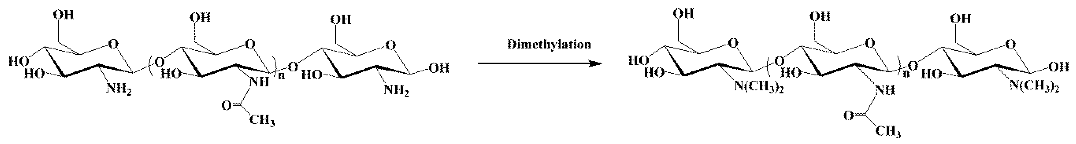
2.2. Synthesis of Dimethyl Chitosan
2.3. Chloromethylation and Quaternization of Polysulfone
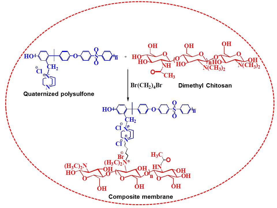
2.4. Cross-Linking and Membrane Fabrication
2.5. Water Uptake and Swelling Ratio
2.6. Ion Exchange Capacity (IEC)
2.7. Analysis/Characterization
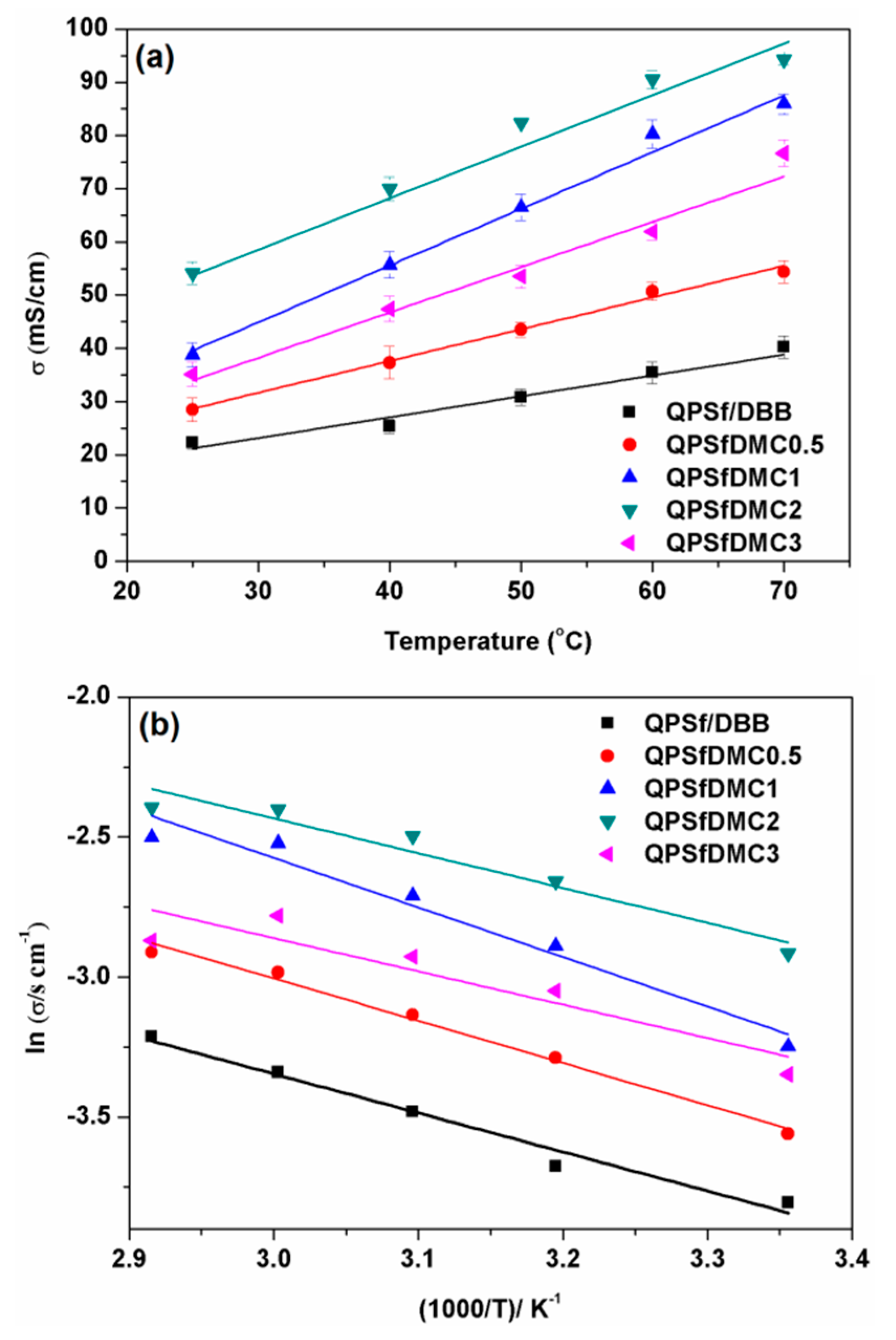
2.8. Ionic Conductivity
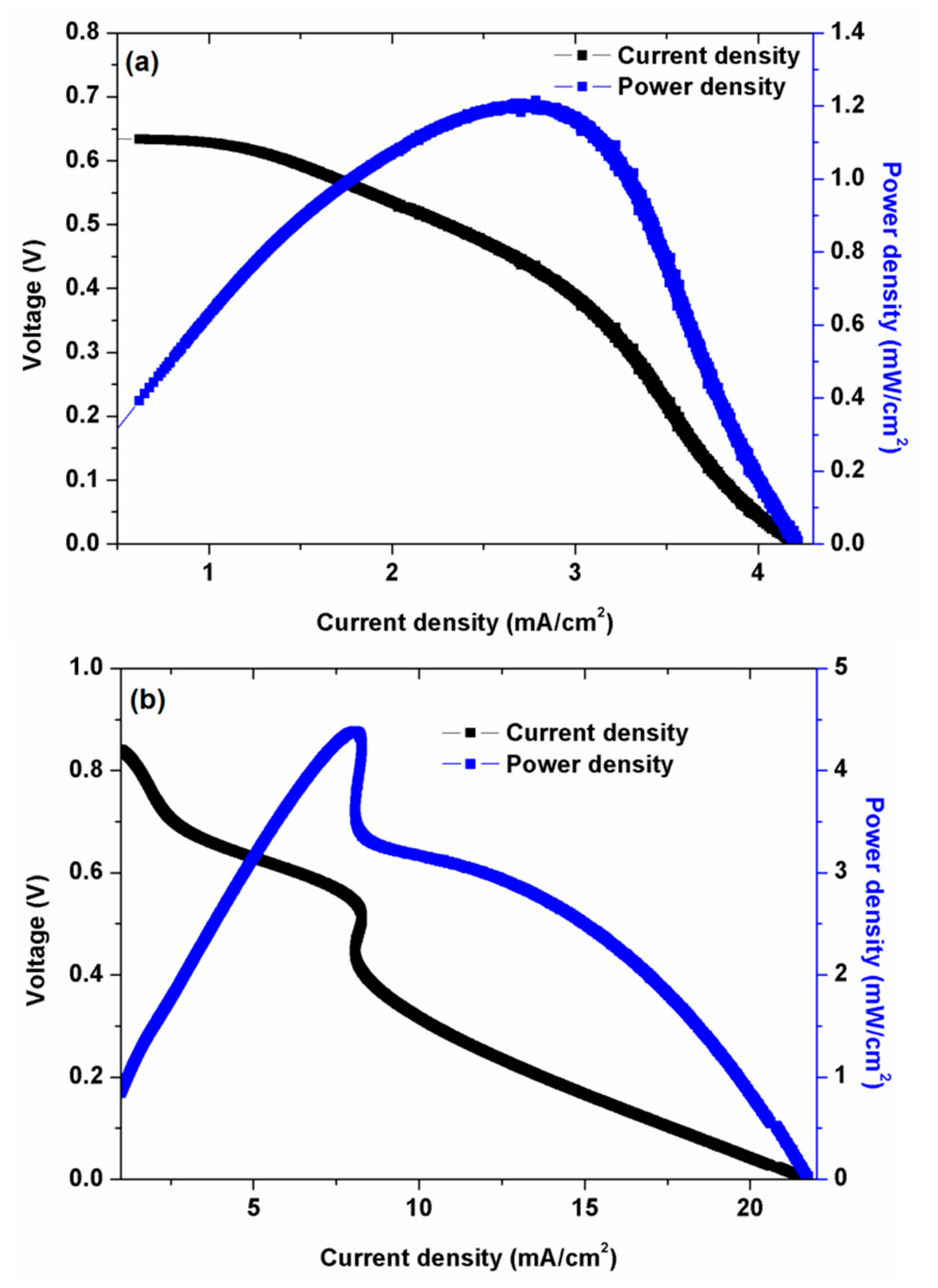
2.9. Fuel Cell Testing and Analysis
3. Results and Discussions
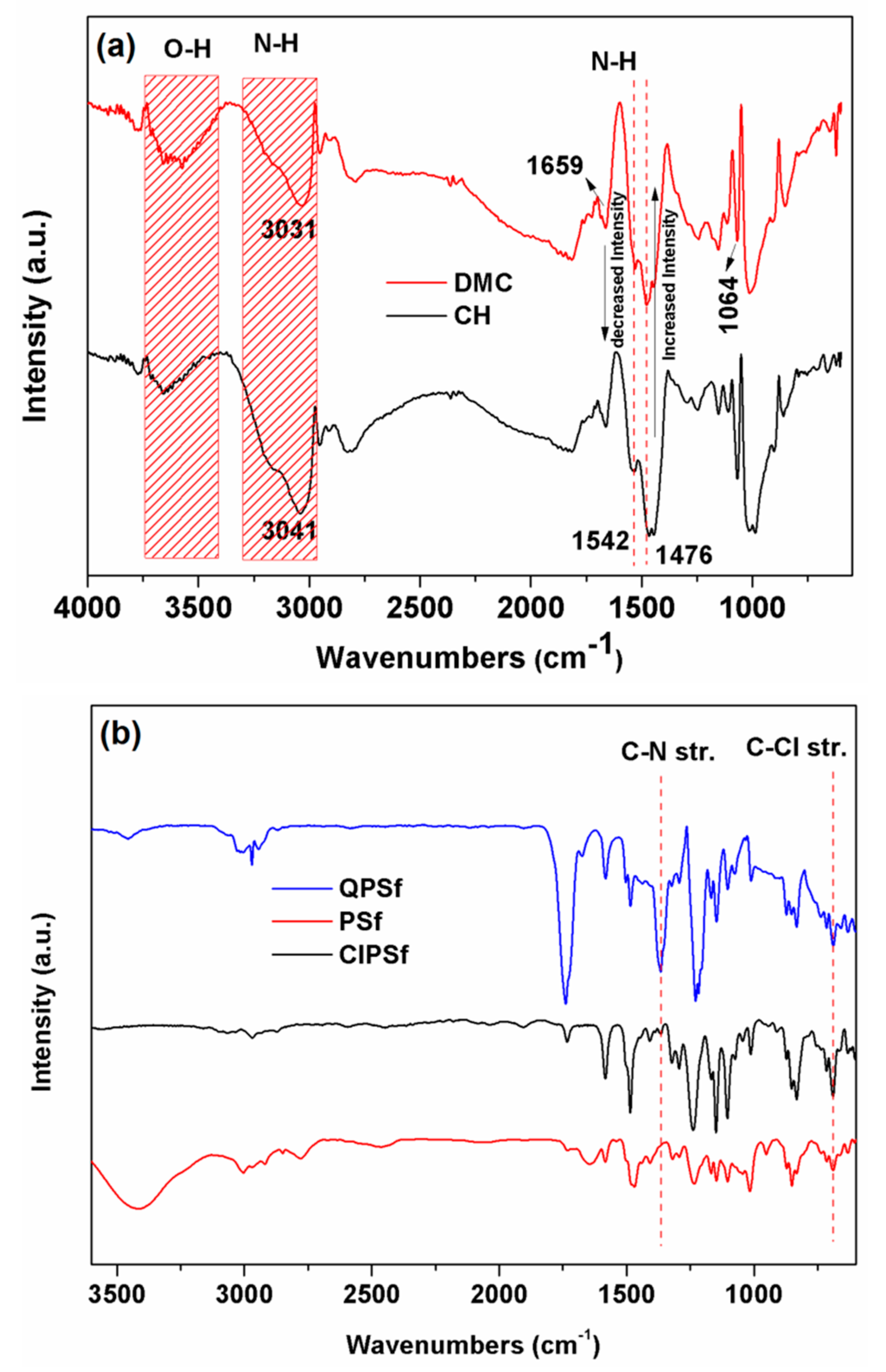
3.1. FTIR and NMR Analysis
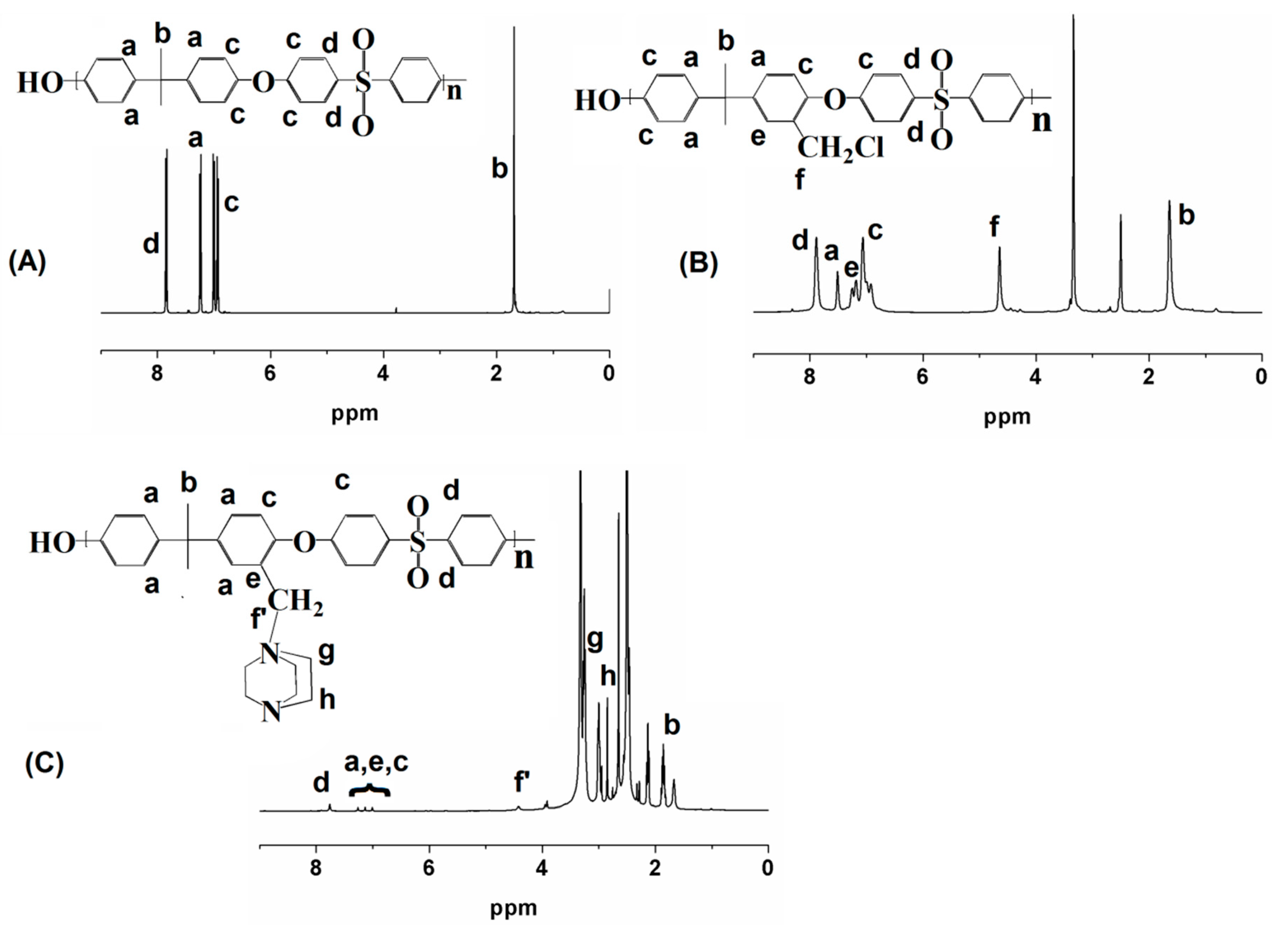
3.2. NMR Analysis
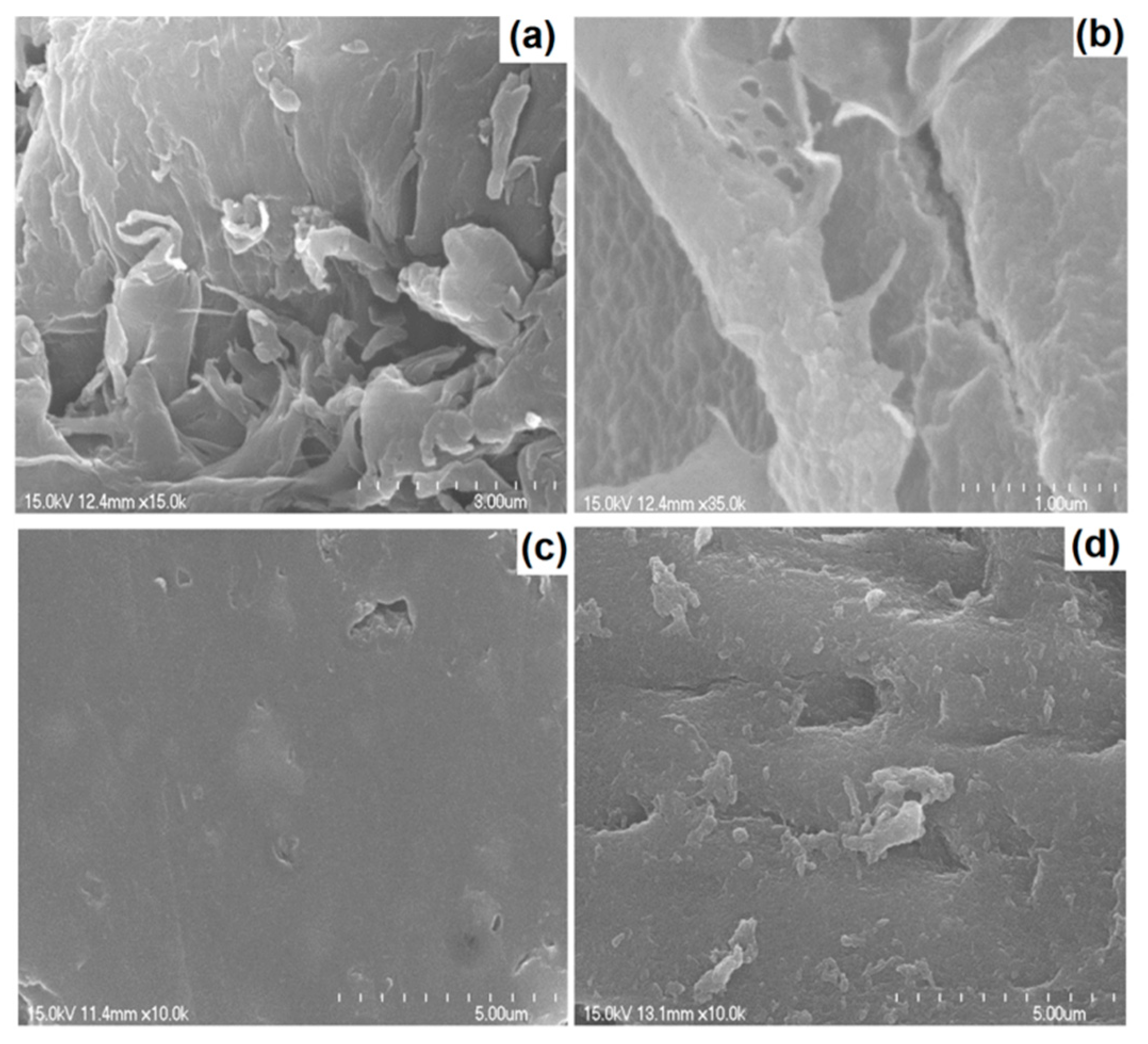
3.3. SEM Analysis
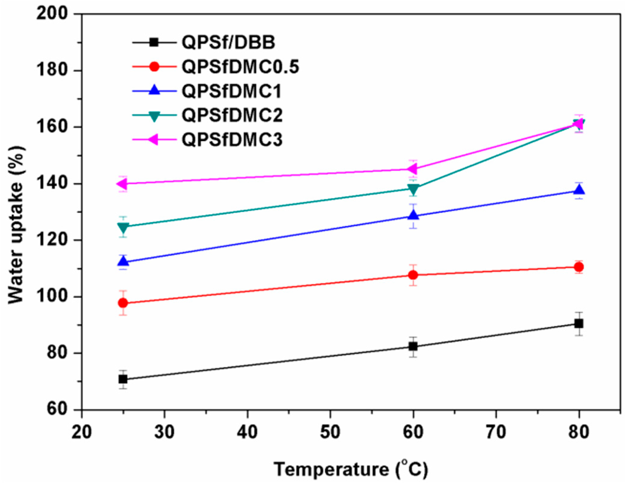
3.4. Properties of the Composite Membranes
3.5. Fuel Cell Analysis
4. Conclusions
Author Contributions
Funding
Conflicts of Interest
References
- Varcoe, J.R.; Slade, R.C. Prospects for Alkaline Anion-Exchange Membranes in Low Temperature Fuel Cells. Fuel Cells 2005, 5, 187–200. [Google Scholar] [CrossRef]
- Varcoe, J.R.; Atanassov, P.; Dekel, D.R.; Herring, A.M.; Hickner, M.A.; Kohl, P.A.; Kucernak, A.R.; Mustain, W.E.; Nijmeijer, K.; Scott, K.; et al. Anion-exchange membranes in electrochemical energy systems. Energy Environ. Sci. 2014, 7, 3135–3191. [Google Scholar] [CrossRef] [Green Version]
- Ochi, S.; Kamishima, O.; Mizusaki, J.; Kawamura, J. Investigation of proton diffusion in Nafion®117 membrane by electrical conductivity and NMR. Solid State Ionics 2009, 180, 580–584. [Google Scholar] [CrossRef]
- Mauritz, K.A.; Moore, R.B. State of understanding of Nafion. Chem. Rev. 2004, 104, 4535–4586. [Google Scholar] [CrossRef]
- Pham, T.H.; Olsson, J.S.; Jannasch, P. N-Spirocyclic Quaternary Ammonium Ionenes for Anion-Exchange Membranes. J. Am. Chem. Soc. 2017, 139, 2888–2891. [Google Scholar] [CrossRef] [PubMed]
- Zhu, L.; Zimudzi, T.J.; Li, N.; Pan, J.; Lin, B.; Hickner, M.A. Crosslinking of comb-shaped polymer anion exchange membranes via thiol–ene click chemistry. Polym Chem. 2016, 7, 2464–2475. [Google Scholar] [CrossRef]
- Weiber, E.A.; Meis, D.; Jannasch, P. Anion conducting multiblock poly(arylene ether sulfone)s containing hydrophilic segments densely functionalized with quaternary ammonium groups. Polym Chem. 2015, 6, 1986–1996. [Google Scholar] [CrossRef] [Green Version]
- Han, J.; Zhu, L.; Pan, J.; Zimudzi, T.J.; Wang, Y.; Peng, Y.; Hickner, M.A.; Zhuang, L. Elastic long-chain multication cross-linked anion exchange membranes. Macromolecules 2017, 50, 3323–3332. [Google Scholar] [CrossRef]
- Yu Xu, P.; Yi Guo, T.; Hui Zhao, C.; Broadwell, I.; Gen Zhang, Q.; Liu, Q.L. Anion exchange membranes based on poly(vinyl alcohol) and quaternized polyethyleneimine for direct methanol fuel cells. J. Appl. Polym. Sci. 2013, 128, 3853–3860. [Google Scholar] [CrossRef]
- Wu, L.; Xu, T. Improving anion exchange membranes for DMAFCs by inter-crosslinking CPPO/BPPO blends. J. Membr. Sci. 2008, 322, 286–292. [Google Scholar] [CrossRef]
- Morandi, C.G.; Peach, R.; Krieg, H.M.; Kerres, J. Novel morpholinium-functionalized anion-exchange PBI-polymer blends. J. Mater. Chem. A 2015, 3, 1110–1120. [Google Scholar] [CrossRef]
- Zarrin, H.; Fu, J.; Jiang, G.; Yoo, S.; Lenos, J.; Fowler, M.; Chen, Z. Quaternized Graphene Oxide Nanocomposites as Fast Hydroxide Conductors. ACS Nano 2015, 9, 2028–2037. [Google Scholar] [CrossRef]
- Li, J.; Yan, X.; Zhang, Y.; Zhao, B.; He, G. Enhanced hydroxide conductivity of imidazolium functionalized polysulfone anion exchange membrane by doping imidazolium surface-functionalized nanocomposites. RSC Adv. 2016, 6, 58380–58386. [Google Scholar] [CrossRef]
- Yang, T.; Li, Z.; Lyu, H.; Zheng, J.; Liu, J.; Liu, F.; Zhang, Z.; Rao, H. A graphene oxide polymer brush based cross-linked nanocomposite proton exchange membrane for direct methanol fuel cells. RSC Adv. 2018, 8, 15740–15753. [Google Scholar] [CrossRef] [Green Version]
- Yang, Q.; Lin, C.X.; Liu, F.H.; Li, L.; Zhang, Q.G.; Zhu, A.M.; Liu, Q.L. Poly (2,6-dimethyl-1,4-phenylene oxide)/ionic liquid functionalized graphene oxide anion exchange membranes for fuel cells. J. Membrane Sci. 2018, 552, 367–376. [Google Scholar] [CrossRef]
- Wang, C.; Lin, B.; Qiao, G.; Wang, L.; Zhu, L.; Chu, F.; Feng, T.; Yuan, N.; Ding, J. Polybenzimidazole/ionic liquid functionalized graphene oxide nanocomposite membrane for alkaline anion exchange membrane fuel cells. Mater. Lett. 2016, 173, 219–222. [Google Scholar] [CrossRef]
- Zhang, H.; Shi, B.; Ding, R.; Chen, H.; Wang, J.; Liu, J. Composite Anion Exchange Membrane from Quaternized Polymer Spheres with Tunable and Enhanced Hydroxide Conduction Property. Ind. Eng. Chem. Res. 2016, 55, 9064–9076. [Google Scholar] [CrossRef]
- Wu, X.; Chen, W.; Yan, X.; He, G.; Wang, J.; Zhang, Y.; Zhu, X. Enhancement of hydroxide conductivity by the di-quaternization strategy for poly(ether ether ketone) based anion exchange membranes. J. Mater. Chem. A 2014, 2, 12222–12231. [Google Scholar] [CrossRef]
- Wang, X.; Li, M.; Golding, B.T.; Sadeghi, M.; Cao, Y.; Yu, E.H.; Scott, K. A polytetrafluoroethylene-quaternary 1,4-diazabicyclo-[2.2.2]-octane polysulfone composite membrane for alkaline anion exchange membrane fuel cells. Int. J. Hydrog. Energy 2011, 36, 10022–10026. [Google Scholar] [CrossRef]
- Tsai, T.H.; Maes, A.M.; Vandiver, M.A.; Versek, C.; Seifert, S.; Tuominen, M.; Liberatore, M.W.; Herring, A.M.; Coughlin, E.B. Synthesis and structure–conductivity relationship of polystyrene-block-poly (vinyl benzyl trimethylammonium) for alkaline anion exchange membrane fuel cells. J. Polym. Sci. B 2013, 51, 1751–1760. [Google Scholar] [CrossRef]
- Lee, K.H.; Cho, D.H.; Kim, Y.M.; Moon, S.J.; Seong, J.G.; Shin, D.W.; Sohn, J.-Y.; Kim, J.F.; Lee, Y.M. Highly conductive and durable poly(arylene ether sulfone) anion exchange membrane with end-group cross-linking. Energy Environ. Sci. 2017, 10, 275–285. [Google Scholar] [CrossRef]
- He, Y.; Si, J.; Wu, L.; Chen, S.; Zhu, Y.; Pan, J.; Ge, X.; Yang, Z.; Xu, T. Dual-cation comb-shaped anion exchange membranes: Structure, morphology and properties. J. Membr. Sci. 2016, 515, 189–195. [Google Scholar] [CrossRef]
- Nagarale, R.K.; Gohil, G.S.; Shahi, V.K.; Rangarajan, R. Preparation of organic–inorganic composite anion-exchange membranes via aqueous dispersion polymerization and their characterization. J. Colloid Interface Sci. 2005, 287, 198–206. [Google Scholar] [CrossRef]
- Liu, J.; Qu, R.; Peng, P.; Liu, W.; Chen, D.; Zhang, H.; Liu, X. Covalently functionalized graphene oxide and quaternized polysulfone nanocomposite membranes for fuel cells. RSC Adv. 2016, 6, 71305–71310. [Google Scholar] [CrossRef]
- Nonjola, P.T.; Mathe, M.K.; Modibedi, R.M. Chemical modification of polysulfone: Composite anionic exchange membrane with TiO2 nano-particles. Int. J. Hydrog. Energy 2013, 38, 5115–5121. [Google Scholar] [CrossRef]
- Liang, N.; Liu, W.; Zuo, D.; Peng, P.; Qu, R.; Chen, D.; Zhang, H. Quaternized polysulfone-based nanocomposite membranes and improved properties by intercalated layered double hydroxide. Polym. Eng. Sci. 2018, 58, 767–774. [Google Scholar] [CrossRef]
- Das, G.; Park, B.J.; Yoon, H.H. A bionanocomposite based on 1, 4-diazabicyclo-[2.2. 2]-octane cellulose nanofiber cross-linked-quaternary polysulfone as an anion conducting membrane. J. Mater. Chem. A 2016, 4, 15554–15564. [Google Scholar] [CrossRef]
- Di Vona, M.L.; Casciola, M.; Donnadio, A.; Nocchetti, M.; Pasquini, L.; Narducci, R.; Knauth, P. Anionic conducting composite membranes based on aromatic polymer and layered double hydroxides. Int. J. Hydrog. Energy 2017, 42, 3197–3205. [Google Scholar] [CrossRef]
- Yu, B.-C.; Wang, Y.-C.; Lu, H.-C.; Lin, H.-L.; Shih, C.-M.; Kumar, S.R.; Lue, S.J. Hydroxide-ion selective electrolytes based on a polybenzimidazole/graphene oxide composite membrane. Energy 2017, 134, 802–812. [Google Scholar] [CrossRef]
- Chen, N.; Liu, Y.; Long, C.; Li, R.; Wang, F.; Zhu, H. Enhanced performance of ionic-liquid-coated silica/quaternized poly(2,6-dimethyl-1,4-phenylene oxide) composite membrane for anion exchange membrane fuel cells. Electrochim. Acta 2017, 258, 124–133. [Google Scholar] [CrossRef]
- Miao, L.; Wang, X.; Fu, Y.; Hu, B.; Bai, Y.; Lü, C. Quaternized polyhedral oligomeric silsesquioxanes (QPOSS) modified polysulfone-based composite anion exchange membranes. Solid State Ionics 2017, 309, 170–179. [Google Scholar] [CrossRef]
- Potts, J.R.; Dreyer, D.R.; Bielawski, C.W.; Ruoff, R.S. Graphene-based polymer nanocomposites. Polymer 2011, 52, 5–25. [Google Scholar] [CrossRef] [Green Version]
- Yuan, Y.; Shen, C.; Chen, J.; Ren, X. Synthesis and characterization of cross-linked quaternized chitosan/poly (diallyldimethylammonium chloride) blend anion-exchange membranes. Ionics 2018, 24, 1173–1180. [Google Scholar] [CrossRef]
- Wang, J.; He, R.; Che, Q. Anion exchange membranes based on semi-interpenetrating polymer network of quaternized chitosan and polystyrene. J. Colloid Interface Sci. 2011, 361, 219–225. [Google Scholar] [CrossRef]
- Wan, Y.; Peppley, B.; Creber, K.A.M.; Bui, V.T.; Halliop, E. Quaternized-chitosan membranes for possible applications in alkaline fuel cells. J. Power Sources 2008, 185, 183–187. [Google Scholar] [CrossRef]
- Li, M.; Chen, Q.; Ma, M.; Liu, X.; Dong, K.; Zhang, Y.; Lu, T. Electrophoretic deposition of core-shell Ag@MSN incorporated-chitosan coatings with biocompatible and antibacterial activities. Mater. Lett. 2019, 239, 29–32. [Google Scholar] [CrossRef]
- Britto, D.; Assis, O.B.G. A novel method for obtaining a quaternary salt of chitosan. Carbohydr. Polym. 2007, 69, 305–310. [Google Scholar] [CrossRef]
- Liao, G.-M.; Yang, C.-C.; Hu, C.-C.; Pai, Y.-L.; Lue, S.J. Novel quaternized polyvinyl alcohol/quaternized chitosan nano-composite as an effective hydroxide-conducting electrolyte. J. Membr. Sci. 2015, 485, 17–29. [Google Scholar] [CrossRef]
- Feketeföldi, B.; Cermenek, B.; Spirk, C.; Schenk, A.; Grimmer, C.; Bodner, M.; Koller, M.; Ribitsch, V.; Hacker, V. Chitosan-Based Anion Exchange Membranes for Direct Ethanol Fuel Cells. J. Membr. Sci. Technol. 2016, 6, 145. [Google Scholar] [CrossRef]
- Wan, Y.; Peppley, B.; Creber, K.A.M.; Bui, V.T.; Halliop, E. Preliminary evaluation of an alkaline chitosan-based membrane fuel cell. J. Power Sources 2006, 162, 105–113. [Google Scholar] [CrossRef]
- Verheul, R.J.; Amidi, M.; van der Wal, S.; van Riet, E.; Jiskoot, W.; Hennink, W.E. Synthesis, characterization and in vitro biological properties of O-methyl free N,N,N-trimethylated chitosan. Biomaterials 2008, 29, 3642–3649. [Google Scholar] [CrossRef]
- Zhang, F.; Zhang, H.; Qu, C. Imidazolium functionalized polysulfone anion exchange membrane for fuel cell application. J. Mater. Chem. A 2011, 21, 12744–12752. [Google Scholar] [CrossRef]
- Taheri, M.; Ghiaci, M.; Shchukarev, A. Cross-linked chitosan with a dicationic ionic liquid as a recyclable biopolymer-supported catalyst for cycloaddition of carbon dioxide with epoxides into cyclic carbonates. New J. Chem. 2018, 42, 587–597. [Google Scholar] [CrossRef]
- Chu, E.; Sidorenko, A. Surface reconstruction by a “grafting through” approach: Polyacrylamide grafted onto chitosan Film. Langmuir 2013, 29, 12585–12592. [Google Scholar] [CrossRef]
- Wu, M.; Long, Z.; Xiao, H.; Dong, C. Preparation of N, N, N-trimethyl chitosan via a novel approach using dimethyl carbonate. Carbohydr. Polym. 2017, 169, 83–91. [Google Scholar] [CrossRef]
- DeCaluwe, S.C.; Baker, A.M.; Bhargava, P.; Fischer, J.E.; Dura, J.A. Structure-property relationships at Nafion thin-film interfaces: Thickness effects on hydration and anisotropic ion transport. Nano Energy 2018, 46, 91–100. [Google Scholar] [CrossRef]
- Hu, B.; Miao, L.; Zhao, Y.; Lü, C. Azide-assisted crosslinked quaternized polysulfone with reduced graphene oxide for highly stable anion exchange membranes. J. Membrane Sci. 2017, 530, 84–94. [Google Scholar] [CrossRef]
- Lan, R.; Tao, S.; Irvine, J.T. A direct urea fuel cell–power from fertiliser and waste. Energy Environ. Sci. 2010, 3, 438–441. [Google Scholar] [CrossRef]
- Xu, W.; Zhang, H.; Li, G.; Wu, Z. Nickel-cobalt bimetallic anode catalysts for direct urea fuel cell. Sci. Rep. 2014, 4, 5863. [Google Scholar] [CrossRef] [Green Version]


| Membrane Code | Water Uptake (%), @ RT * | Ion Exchange Capacity (mmol/g) | Through-Plane Swelling Ration (%) @ RT | In-Plane Swelling Ratio (%) @ RT | Ionic Conductivity (mS/cm) @ 25 °C | Gel Fraction (%) |
|---|---|---|---|---|---|---|
| QPSf/DBB | 70.72 ± 2.10 | 1.20 ± 0.14 | 25.75 ± 2.65 | 28.10 ± 2.52 | 22.25 ± 1.22 | 80 |
| QPSfDMC0.5 | 97.75 ± 1.57 | 1.68 ± 0.25 | 28.21 ± 2.41 | 31.89 ± 2.43 | 28.45 ± 2.24 | 90 |
| QPSfDMC1 | 112.25 ± 2.31 | 2.08 ± 0.11 | 30.33 ± 2.17 | 33.51 ± 1.55 | 38.81 ± 2.37 | 95 |
| QPSfDMC2 | 124.72 ± 2.20 | 2.34 ± 0.17 | 32.31 ± 1.89 | 30.48 ± 1.85 | 54.15 ± 2.10 | 97 |
| QPSfDMC3 | 139.89 ± 2.41 | 1.95 ± 0.10 | 25.07 ± 1.78 | 22.71 ± 2.17 | 35.17 ± 2.33 | 94 |
© 2019 by the authors. Licensee MDPI, Basel, Switzerland. This article is an open access article distributed under the terms and conditions of the Creative Commons Attribution (CC BY) license (http://creativecommons.org/licenses/by/4.0/).
Share and Cite
Das, G.; Kim, C.Y.; Kang, D.H.; Kim, B.H.; Yoon, H.H. Quaternized Polysulfone Cross-Linked N,N-Dimethyl Chitosan-Based Anion-Conducting Membranes. Polymers 2019, 11, 512. https://doi.org/10.3390/polym11030512
Das G, Kim CY, Kang DH, Kim BH, Yoon HH. Quaternized Polysulfone Cross-Linked N,N-Dimethyl Chitosan-Based Anion-Conducting Membranes. Polymers. 2019; 11(3):512. https://doi.org/10.3390/polym11030512
Chicago/Turabian StyleDas, Gautam, Chae Yeon Kim, Dong Ho Kang, Bo Hyeon Kim, and Hyon Hee Yoon. 2019. "Quaternized Polysulfone Cross-Linked N,N-Dimethyl Chitosan-Based Anion-Conducting Membranes" Polymers 11, no. 3: 512. https://doi.org/10.3390/polym11030512