Article

Construction of CNC@SiO2@PL Based Superhydrophobic Wood with Excellent Abrasion Resistance Based on Nanoindentation Analysis and Good UV Resistance

1
College of Chemistry and Materials Engineering, Zhejiang A&F University, Hangzhou 311300, China
2
Shandong Institute for Product Quality Inspection, Jinan 250102, China
*
Authors to whom correspondence should be addressed.
These authors contributed equally to this work.
Polymers 2023, 15(4), 933; https://doi.org/10.3390/polym15040933
Submission received: 17 January 2023 / Revised: 9 February 2023 / Accepted: 9 February 2023 / Published: 13 February 2023
(This article belongs to the Special Issue Properties and Characterization of Polymers in Nanomaterials)

Abstract

:
Construction of superhydrophobic woods with high abrasion resistance is still a major challenge, and micro analysis for abrasion resistance is scarce. To improve these issues, cellulose nanocrystals (CNC)@SiO2@phosphorylated lignin (PL) rods were prepared by SiO2 in situ generated on CNC, and then the modified lignin attached to the CNC@SiO2 rods surface. Subsequently, the superhydrophobic coating was constructed using hydrophobic modified CNC@SiO2@PL rods as the main structural substance by simple spraying or rolling them onto wood surfaces, and both polydimethylsiloxane (PDMS) and epoxy resin were used as the adhesives. The resulting coating had excellent superhydrophobic properties with a water contact angle (WCA) of 157.4° and a slide angle (SA) of 6°. The introduced PL could enhance ultraviolet (UV) resistance of the coating due to the presence of these groups that absorbed UV light in lignin. In the abrasion resistance test, compared with the SiO2/PL coating, the abrasion resistance of the one with CNC was much higher, suggesting that CNC could improve the abrasion resistance of the coating due to its high crystallinity and excellent mechanical strength. The coating with PDMS performed better than the one with epoxy resin because the soft surface could offset part of the external impact by deformation in the abrasion process. This was also consistent with the results of the nanoindentation (NI) tests. In view of the simple preparation and good performance, this superhydrophobic wood will have broad application potential.

1. Introduction

Lignin is an abundant and renewable material and a byproduct of the forestry chemical industry, but it presently has low application value [1]. If treated improperly, it will even cause some environmental pollution [2]. In recent years, research on the application and development of high-value lignin has been in full swing. Research has shown huge potential applications in drug loading, electrochemistry, catalysis, mildew prevention, and other fields [3]. In particular, the successful development of lignin nanospheres played a positive role in expanding the application range of lignin [4]. Lignin itself contains large numbers of ultraviolet (UV) absorbing groups such as benzene rings, carbonyl, double bonds, and other conjugated structures, which have good UV resistance effects [5]. This also lays a foundation for its application in outdoor materials.
Superhydrophobic surfaces with a water contact angle (WCA) > 150° and a slide angle (SA) < 10° show outstanding properties such as self-cleaning, antifouling, ice resistance, drag reduction, oil-water separation, etc. [6,7,8,9], which could have potential applications in various fields and have become one of the hot research spots over the past 30 years. It is well known that the two basic conditions for reaching superhydrophobicity are both suitable micro–nano layered structure and low surface free energy [10]. There are many ways to construct superhydrophobic surfaces. The diversified preparation means, including chemical vapor deposition (CVD) [11], etching, sol-gel [12], self-assembly [13], impression, spraying [14], etc., endowed superhydrophobic surfaces’ rapid development. However, some methods were limited to high-cost equipment, poor environmental processes, and tedious steps, etc., which were difficult to use at scale. Spraying was the most common and convenient way in line with the large-scale application, which was not limited to the shape and size of the sample, etc. To achieve spraying, it is necessary to allow the corresponding material to disperse into the solvent to form a paint. Currently, inorganic nanoparticles were the common substances used to construct superhydrophobic coatings due to their good stability and economic applicability [15]. Although most inorganic superhydrophobic coatings had good stability, their durability was generally relatively poor and needed further improvement. The inorganic superhydrophobic coating binding with lignin was one of the possible methods to improve durability [16].
Besides durability, the mechanical strength of superhydrophobic coatings was thought one of the most difficult problems to solve. Because the superhydrophobic surface was needed to build the micro–nano rough structure, the mechanical stability of such a structure was insufficient to withstand destruction from various external forces [17]. Many methods were proposed to improve it. For example, by using high-strength adhesives, it could estimate the adhesion between the coating and the substrate, but the stability of the micro–nano structure of the coating was also difficult to solve [18]. The mechanical strength of the rough structure formed by the mutual stacking of particles was unstable enough due to the lack of sufficient binding force among particles [6]. Therefore, it is crucial to enhance the stability between the particles of the microstructure [19]. Moreover, the introduction of naturally degradable organic materials to prepare organic–inorganic composite superhydrophobic coatings was conducive to reducing the burden on the environment. The addition of natural polymers might enhance the performance of the coating or introduce other functions. CNC is a rod-like structure material, which is mainly made of plant fibers by acid hydrolysis, and it has negatively charged sulfonic acid groups on its surface. It has emerged as a strengthening material in recent years [20,21]. As in our previous study [6], we proposed using the CNC@SiO2 rods instead of pure SiO2 nanoparticles to build the rough structure of the superhydrophobic coating. Compared with the pure SiO2 coating, the resulting coating showed ultra-high mechanical abrasion resistance. However, its preparation was performed by a two-step process and needed to use a fluorinated reagent during modification in ethanol solvent, which needs to be improved in terms of simplicity, aging resistance, and environmental protection.
Here, to improve the above problems, the superhydrophobic coating with a fluorine-free reagent was prepared with a one-step spray. The phosphorylated lignin (PL) was introduced onto the CNC@SiO2 rods to improve its aging resistance and to enhance its durability [22], as well as be conducive to the dispersion of the rods due to the negative charge on the surface of phosphorylated lignin [23]. Wood was chosen as the substrate due to its strong hydrophility, which is easily affected by the humidity of the surrounding air, showing poor dimensional stability. As well as with the long-time radiation of UV light on wood, there will be the formation of free radicals on the wood surface. The molecular chain of cellulose and hemicellulose is easily destroyed by free radicals, reducing the stability and durability of wood [24]. Therefore, it needs to be modified as hydrophobic and improve its aging resistance to enhance its dimensional stability and UV resistance. It is also difficult to accurately evaluate the mechanical properties of superhydrophobic coatings only by sandpaper abrasion. Nanoindentation technology is generally used to analyze the bond strength of the interface and to receive feedback on the strength region of the interface through the change of the probe mechanical curve [25]. Here, we also tried to evaluate the mechanical strength of superhydrophobic coatings based on the nanomechanics method, which reflected the strength of the constructed micro–nano structures.

2. Eexperimental Section

2.1. Materials

Enzymatic hydrolysis lignin raw material (content of about 20%) was purchased from Hong Kong Laihe Biotechnology Co., Ltd. Cellulose nanocrystals (CNC) aqueous suspension with a concentration of 12% was purchased from the process development center, the University of Maine, USA. Tetraethyl orthosilicate (TEOS, 98%), ammonium hydroxide (25%), anhydrous ethanol (99%), and sodium phosphate dibasic dodecahydrate (Na2HPO4∙12H2O, white crystalline powder) were purchased from Macklin, China. Both methyltrimethoxysilane (MTMS, C4H12O3Si, Mw~136.22, 98%) and hexadecyltrimethoxysilane (HDTMS, C19H12O3Si, Mw~346.62, 85%) as the combined modifiers were purchased from Sigma-Aldrich, China. Polydimethylsiloxanes (PDMS, (C2H6OSi)n, Sylgard 184 silicone elastomer) including its curing agent was purchased from Dow Corning Inc. The epoxy resin (two-component, clear, quick-setting) was purchased from the J-B Weld company, Sulphur Springs, TX, USA. Beech was cut into a series of small pieces of wood (length × width x height = 3 × 2 × 2) and used as the substrates.

2.2. Eexperimental Methodology

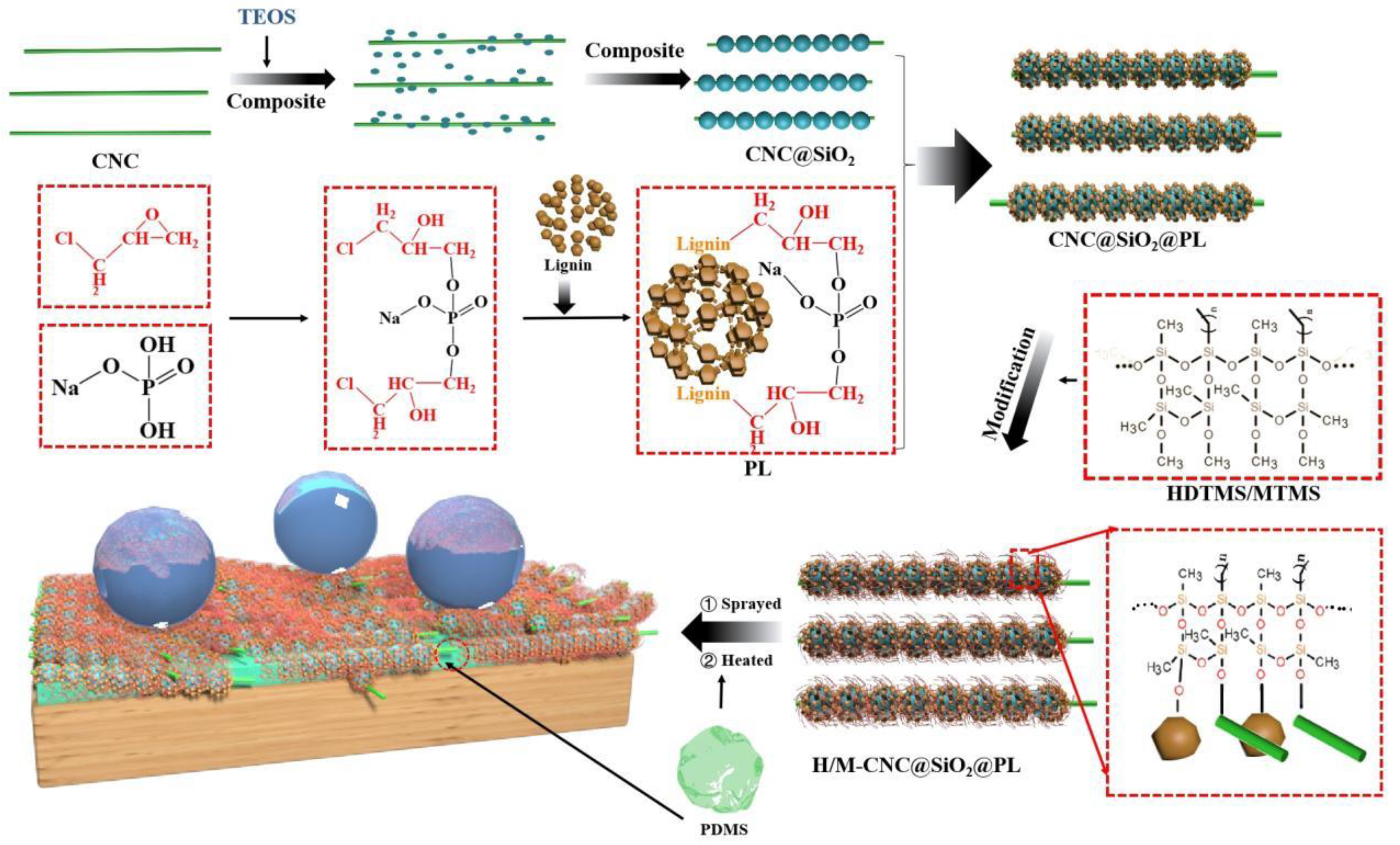
2.2.1. Preparation of CNC@SiO2 Rod

The preparation process of CNC@SiO2 rod is shown in Figure 1. SiO2 grew on the surface of CNC as the axis under alkaline conditions to form CNC@SiO2 rods. Exactly as described in our previous study [6], CNC aqueous suspension was replaced with ethanol suspension by dialysis for three days, with the replacement of fresh ethanol every 12 h. The CNC ethanol suspension was diluted to a concentration of 1.5 wt%, mixed with ammonium hydroxide solution and TEOS with the volume ratio of 50:4:4, and stirred with 500 rad/min at 55 °C for ~2 h under sealing to a CNC@SiO2 rod mixture.

2.2.2. Preparation of Phosphorylated Lignin (PL)

According to the reports [26], 35.8 g of Na2HPO4∙12H2O was dissolved in a flask with 50 g of distilled water at 50 °C and synthesized through adding 10 g of epichlorohydrin drop by drop, followed by keeping it at 85 °C for 5 h. Here, an intermediate (3-chloro-2-hydroxypropyl phosphate) was produced by the ring-open process and reaction with Na2HPO4∙12H2O of epichlorohydrin (Figure 1). After adjusting the pH to 11, lignin extracted by ethanol was added, and stirring continued for 5 h to get the phosphorylated lignin (marked as PL). PL was obtained by grafting phosphate groups onto the benzene rings of the lignin molecules under the substitution reaction between the intermediate and the active sites of lignin.

2.2.3. Synthesis and Modification of CNC@SiO2@PL Rod

CNC@SiO2 water–ethanol suspension (water:ethanol = 6:1 v/v) was prepared and sonicated with a cell crushing apparatus at 500 W for 15 min. PL (mass ratio of PL:CNC@SiO2 = 1.3:1) was added to the CNC@SiO2 suspension and stirred for 30 min. Then, the pH of the system was adjusted to 3.5, and stirring continued for 30 min to get the CNC@SiO2@PL rods [27]. Both MTMS and HDTMS as the combined modifiers were added to the system, and stirring continued for ~4 h to achieve a sufficient reaction. Because both MTMS and HDTMS could mutually promote the hydrolysis in a certain concentration of ethanol solution, followed by dehydration and condensation to form a long hydrophobic carbon chain (as shown in Figure 1). Subsequently, the above mixture was placed in an oven at 40 °C for 1 h. Finally, the sample was collected by filtration with filter paper, followed by washing four times with distilled water and drying to obtain the hydrophobic CNC@SiO2@PL rods powder.

2.2.4. Preparation of CNC@SiO2@PL Superhydrophobic Coating

The modified CNC@SiO2@PL mixture was redispersed in ethanol by magnetic stirring and adjusted to the concentration of 1.5 wt%, followed by adding PDMS (including its curing agent taking up PDMS of 1/10) as the adhesive at the half dosage to the CNC@SiO2@PL rods to obtain the hydrophobic paint. Subsequently, the hydrophobic paint was sprayed using a spray gun or spun by a rotary coating machine onto the substrate surface. Finally, the CNC@SiO2@PL@PDMS superhydrophobic coating was obtained after drying at 150° for 2 h.
To compare the influence of different adhesives on the mechanical strength of the CNC@SiO2@PL-based superhydrophobic coatings, epoxy resin was also used as the adhesive. First, the epoxy was treated on the wood surface. After 3~5 min, the CNC@SiO2@PL mixture was sprayed or rolled onto the surface of the epoxy layer, followed by standing for 1 h in the oven at 80 °C to obtain the CNC@SiO2@PL@epoxy superhydrophobic coating.

2.3. Characterization

Surface morphologies and microstructure of both different coatings and various rods were observed by scanning electron microscopy (SEM, FEI company, Hillsboro, OR, USA) and transmission electron microscopy (TEM, Zeiss, Oberkochen, Germany). The chemical compositions and elemental change of both lignin and CNC@SiO2@PL rods before and after modification were tested by Fourier transform infrared spectrometer (FTIR, PerkinElmer, Waltham, MA, USA) with the wavenumber range of 400~4000 cm−1 and 32 times of scanning) and X-ray photoelectron spectroscopy (XPS, PHI-5300 photoelectron spectrometer, PerkinElmer Instruments Co., Ltd., Waltham, USA). WCAs of different coatings were measured by a commercial contact angle meter (Shanghai Zhongchen JC2000D, China) with a rotatable sample platform, the sample was placed on the sample platform, and liquid droplets of 4–8 µL were dropped onto the sample surface through a controlled syringe, followed by adjusting the accuracy and measuring. The SAs were measured by tilting the sample platform until the liquid droplets started to roll, and the angle of rotation was taken as the SA. The measured result was taken at the average value of five random measurements.
The nanoindentation (NI) analysis of the coatings was conducted by a Berkovich indenter which was equipped with the iMicro nanoindenter (KLA corporation, San Francisco, USA) system. As described in the report [28], the NI sample prepared by the coating was uniformly spread on the substrate, and then the polished coating was uniformly spread on the substrate by an ultra-microtome (Leica MZ6, Germany) equipped with a diamond knife. NI mapping in a recently reported methodology [29] was utilized to analyze the static mechanical properties of the wood–adhesive interphase to obtain the corresponding cartographies of the mechanical performance. An array of 30 × 30 indents was conducted with a peak force of 200 μN in a covered area of 30 × 30 μm2. The reduced elastic modulus (Er) and hardness (H) can be calculated with the methodology developed by Oliver and Pharr in 1992 (Equations (1) and (2)). Since the 1970s, the relationship between stiffness, reduced elastic modulus, and the projected area had been obtained by analyzing the influence between indentation depth and load. However, the relationship was limited to the analysis of the results from cylindrical and conical indenters, not applicable to the results from the spring back of samples. Therefore, Oliver and Pharr developed a nanoindentation test method using a Berkovich indenter and taking into account the change in projected area due to sample rebound, which is the method used today. Please refer to [30] for details.
E r = π 2 β S A
H = P m a x A
S (mN/mm) is the initial unloading stiffness, and β refers to a correction factor correlated to the indenter’s geometry (β = 1.034 for a Berkovich indenter). A (µm2) stands for the projected contact area at peak load. Pmax (µN) corresponds to the peak load of indent.

2.4. Sandpaper Abrasion and UV Resistance Test

The sandpaper abrasion test was described in our previous study [6]. For this test, the coated side of the sample was placed on sandpaper (300 grit), and the loading with 50 g of weight was applied to the uncoated side of the sample. Then, the sample was moved forward by 10 cm under an action of the external force and returned to the original position in the same way. This was taken as one abrasion cycle. After each abrasion cycle, the WCAs were measured. The sandpaper abrasion test was not stopped until the average value of WCAs was less than 150°. The UV resistance test was conducted by placing the samples in a UV aging test chamber at a distance of 20 cm from the light source, and the WCAs and SAs were measured each 1 h (or 12 h) until the average value of WCAs was <150°. There were two kinds of UV light used, one with 15 W of power and a wavelength of 265 nm, and the other with 1000 W of power and a wavelength of 356 nm [31].

3. Results and Discussions

3.1. Surface Morphology

As shown in the TEM images above, SiO2 nanoparticles grew in situ on the surface of CNCs to form the rod-bead type of CNC@SiO2 complex (Figure 2a), their diameter was about 20~50 nm. With the introduction of PL, it was obvious that the diameter of the CNC@SiO2@PL rods (Figure 2b), increased to about 30~80nm. The PL was precipitated onto the surface of the CNC@SiO2 rods to form a wrinkled surface, which was conducive to the promotion of the nanoscale structure. As shown in the SEM images, the wood surface was ragged due to uneven gullies formed from damaged conduits (Figure 2d), and SiO2 formed a coating on the wood by stacking with each other (Figure 2e). In the CNC@SiO2 coating (Figure 2f), its disorderly accumulation could build a better air nest due to the rod-like structure with a high length–diameter ratio, which was conducive to reducing the actual contact area between the water droplets and the coating surface, corresponding to the Cassie model [32]. This suggested that CNC@SiO2 rods were more suitable as the rough structure of superhydrophobic coatings, which also proved that the WCA of the CNC@SiO2 coating was higher than that of the pure SiO2 one (as shown in the section “Wettability Analysis”). In addition, CNC connecting SiO2 in series could improve the stability of the structure, which would be reflected in the following sandpaper abrasion test. Similarly, the CNC@SiO2@PL coating had better stability and superhydrophobicity than the SiO2@PL one (Figure 2g,h). The introduction of a small amount of PDMS had no significant effect on both the diameter of the CNC@SiO2@PL rods (Figure 2c) and the microstructure of the coating, which was mainly deposited on the bottom of the coating to provide adhesion.

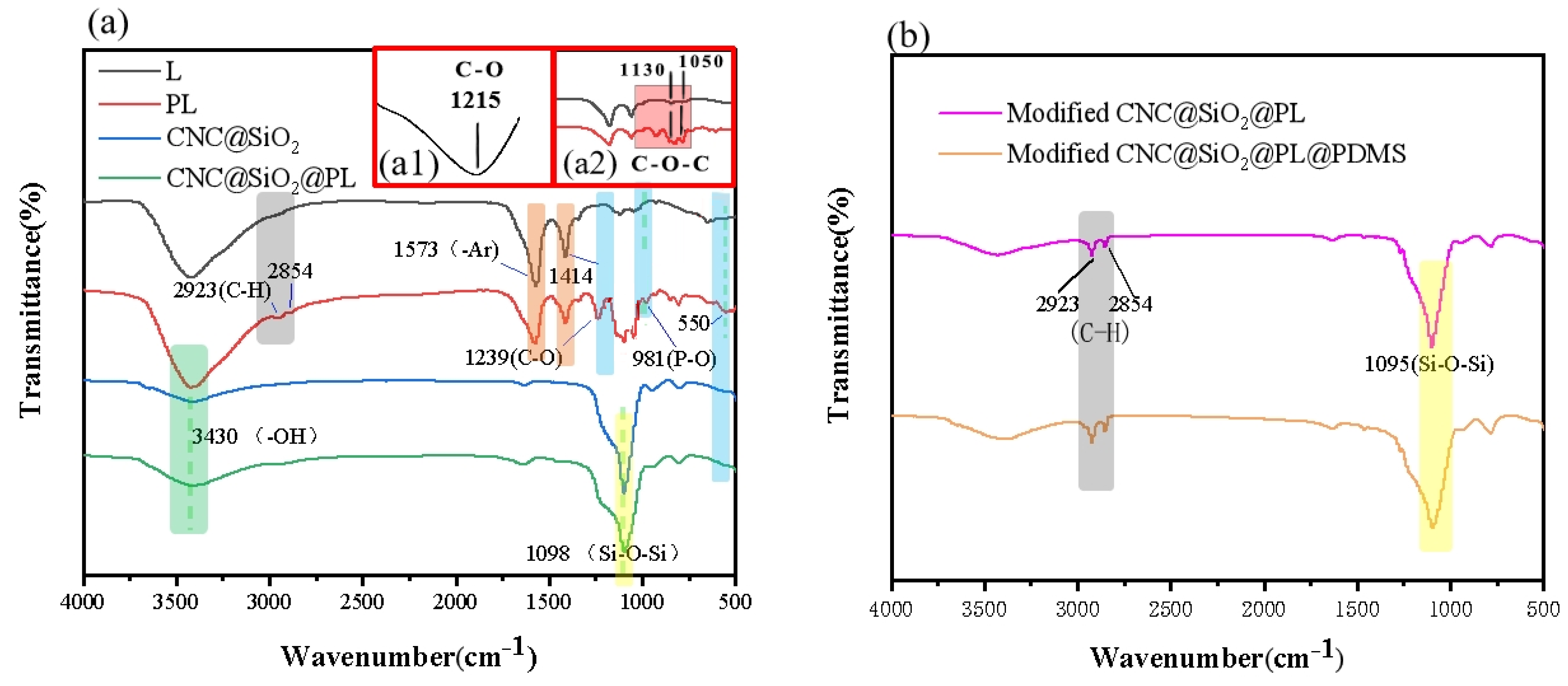
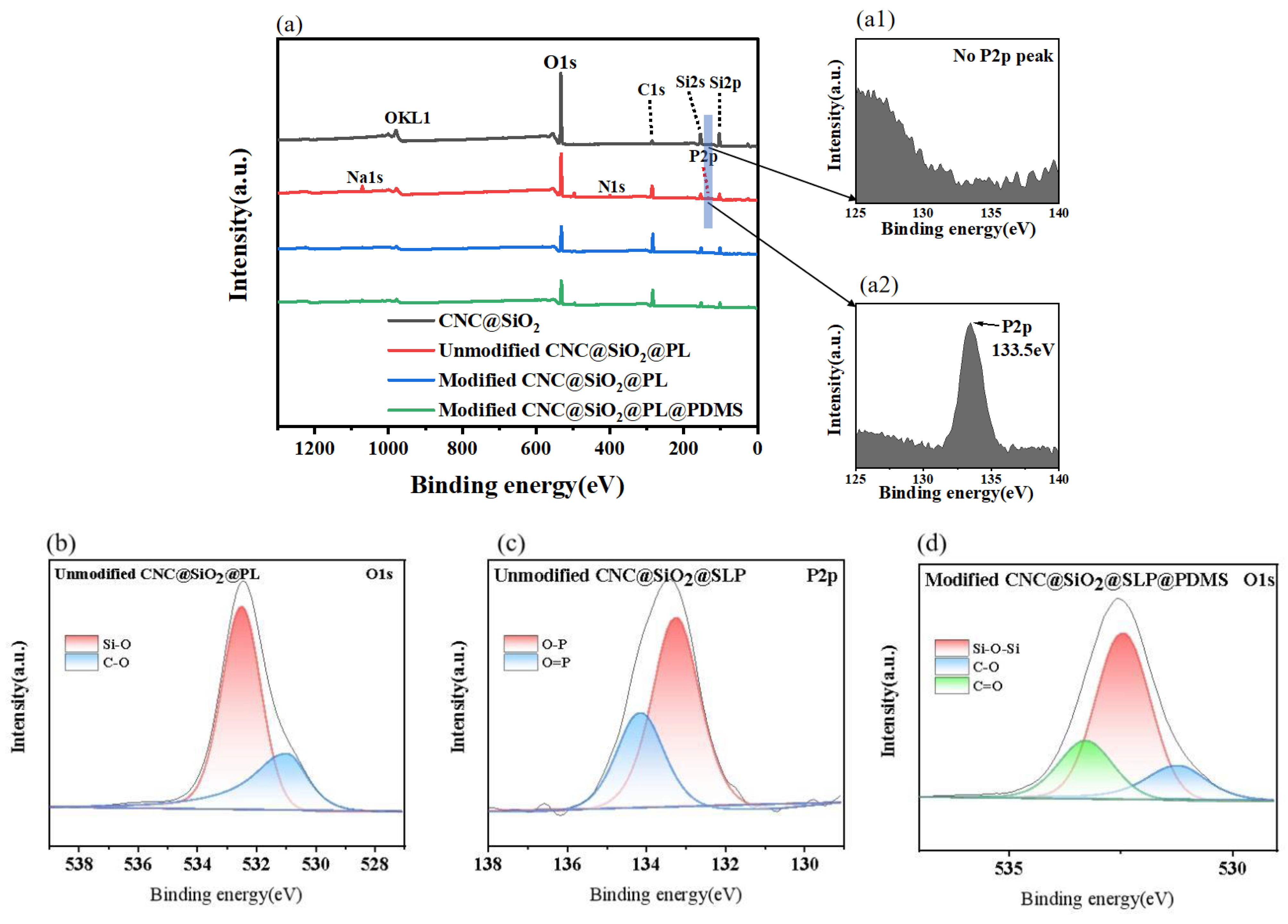
3.2. Chemical Composition Analysis

In the system, the chemical composition was analyzed by FTIR (as shown in Figure 3a). According to the FTIR spectrum of lignin (marked L), before modification, the skeleton vibration of aromatic ring in the lignin appeared at 1573, 1414 cm−1 [33]. The absorption peak at 1215 cm−1 (Figure 3(a1)) was related to the stretching vibrations of the C–O bonds, and the absorption peaks (1130, 1050 cm−1) were mainly caused by the stretching vibrations of C–O–C bonds [34]. After modification, the phosphate groups were introduced to lignin to form PL by the substitution reaction of the –CH2Cl of the intermediate (3-chloro-2-hydroxypropyl phosphate) and the active sites of lignin. The stretching vibrations of the C–O bonds were moved to 1239 cm−1 due to the influence of the intermediate. The vibration peak of the phosphate group appeared at 550 cm−1 and 981 cm−1 [26,35], indicating that the phosphorylation modification of lignin was successful, which was consistent with the analysis in Figure 1. In the CNC@SiO2 rods, it could be seen that the absorption peak at 3430 cm−1 was caused by the rich –OH groups, and the absorption peak at 1098 cm−1 was caused by Si–O–Si bonds. The stretching vibrations of the C–H bonds were related to the peaks at 2923 and 2854 cm−1, and it could be seen that the peak strength of the CNC@SiO2@PL after hydrophobic modification was enhanced. This was caused by the large amounts of methyl from both MTMS and HDTMS. After combining with the PL, the CNC@SiO2@PL rods showed similar peaks as before the combination, indicating the successful attachment of PL. After further hydrophobic modification by MTMS and HDTMS and the introduced PDMS as the adhesive (Figure 3b), the absorption peaks at 1095 cm−1 resulting from the Si–O–Si bonds coincided with that of SiO2, it was difficult to judge the success of modification by FTIR.
Therefore, XPS was further used to verify the attachment of modifiers and to characterize the changes of surface elements of samples. The elements Si, O, and C could be clearly seen in the CNC@SiO2 rods (Figure 4a). In particular, element Si was obviously higher than element C because SiO2 was in the outermost layer and CNC was in the inner layer. When the PL was introduced, the peak intensity of element Si decreased, element P appeared, and the O–P bond existed (Figure 4b,c), directly indicating the successful covering of the PL. After further hydrophobic modification by MTMS, HDTMS, and the introduced PDMS, compared with that before modification, there were no new elements, because they both had the same chemistry bonds (Figure 4d). In Figure 5b, the Si–O bonds were from SiO2, whereas in Figure 5d, the Si–O–Si bonds were more commonly formed by the interaction of MTMS and HDTMS (as shown in Figure 1). The C=O bonds from CNC were detected in Figure 5d, but not in Figure 5b. It was possible that MTMS and HDTMS modifiers interact stronger with PL and SiO2, exposing CNC to the surface of the composite. Moreover, in the change of its element proportion, the element C further increased and the element Si reduced (as shown in Table 1), which could indirectly prove the successful attachment of the modifiers.

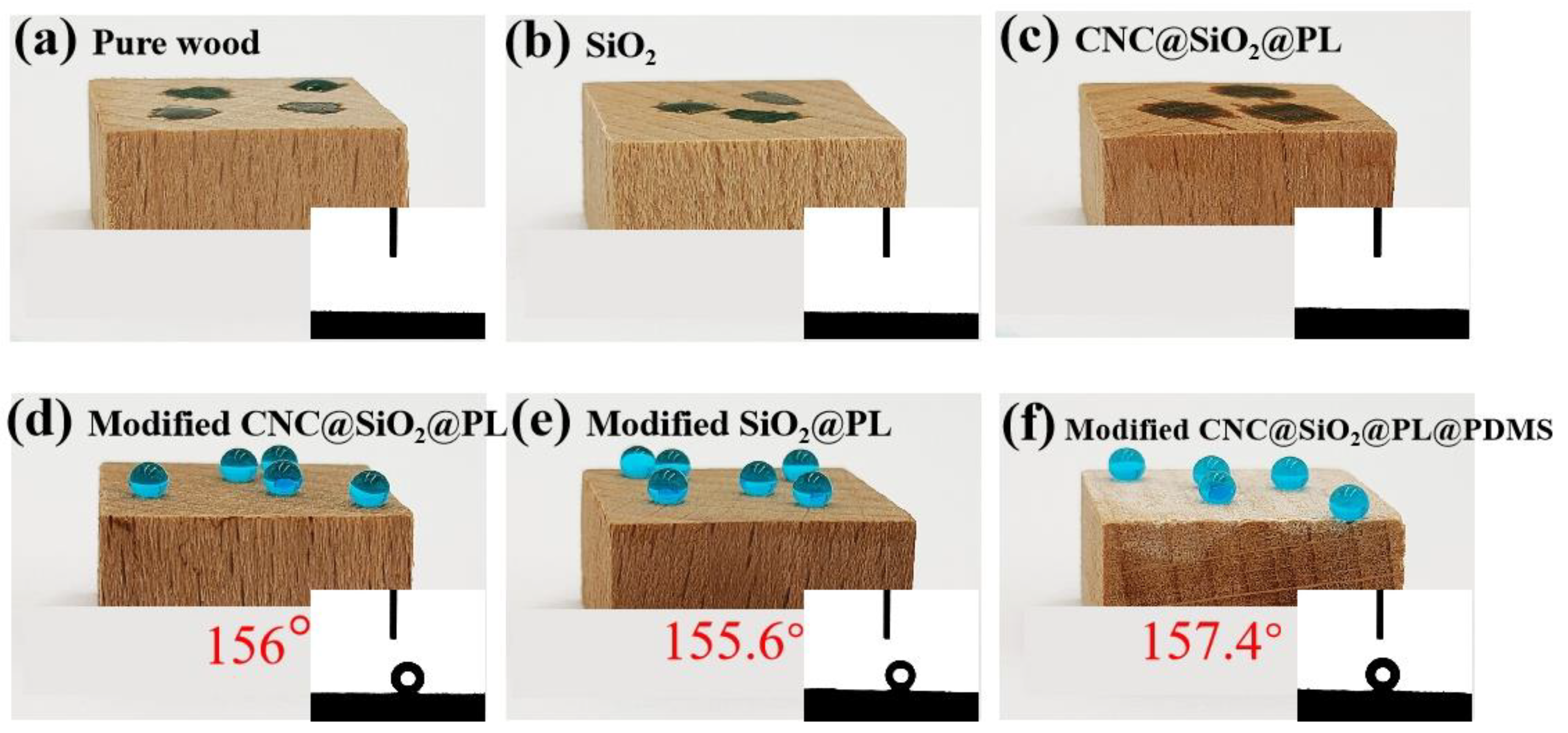
3.3. Wettability Analysis

As we all know, pure wood is mainly composed of cellulose, hemicellulose, and lignin, and it contains rich hydroxyl groups which easily absorb moisture (Figure 5a), resulting in poor dimensional stability and even the production of mildew [31]. This was also the reason that researchers were committed to the hydrophobic modification of wood. When the wood was treated only with the unmodified SiO2 nanoparticles, the sample showed stronger hydrophilicity (Figure 5b) than the pure wood due to their richer active hydroxyl groups. It is well known that lignin has fewer hydroxyl groups on its surface and its hydrophilicity is weak. After lignin was phosphorylated, the hydrophilicity of the resulting PL was enhanced. Therefore, the CNC@SiO2@PL-coated wood still showed good hydrophilicity (as shown in Figure 5c). After the introduced MTMS and HDTMS as the combined modifiers, the modified CNC@SiO2@PL and SiO2@PL coatings showed stable WCAs of 156° and 155.6°, and SAs of 6° and 7°, respectively (in Figure 5d,e). The variation of WCAs had no large change after the droplets were maintained for 1 h. This was due to the fact that the long hydrophobic chains formed from dehydration and condensation of the combined modifiers were attached to the surface of SiO2@PL and CNC@SiO2@PL rods, reducing their surface free energy. The modified SiO2@PL and CNC@SiO2@PL rods could be used to construct the superhydrophobic coatings by stacking them on top of each other.
It can be seen from the above that the presence of CNC had little influence on the wettability, which was mainly used to enhance the stability of the microscopic rough structure. PDMS, as a hydrophobic adhesive, was introduced to the system mainly to provide adhesion between the coating and the substrate. The WCA of CNC@SiO2@PL@PDMS reached 157.4° (Figure 5f) and the SA only 6°. As shown in Table 2, compared with other coatings, the WCA of CNC@SiO2@PL@PDMS was not inferior, proving that it had excellent superhydrophobic properties.

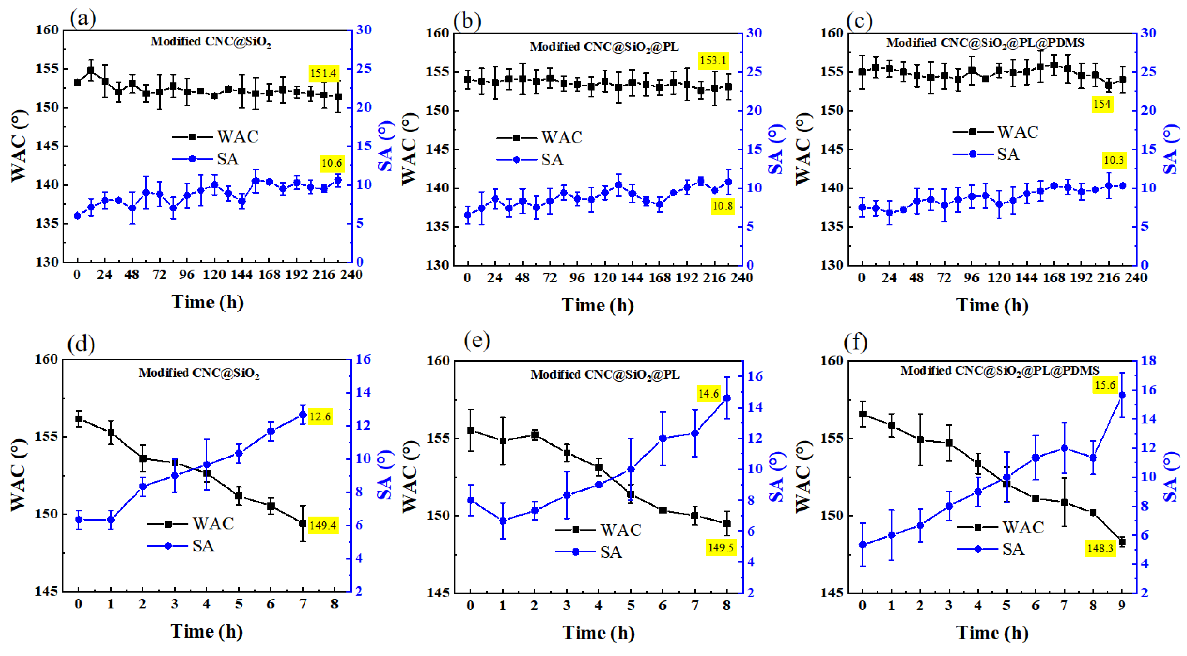
3.4. UV Resistance Test

When the prepared superhydrophobic coating was used outside, it would undoubtedly be exposed to the UV radiation from sunlight. Although most of the UV radiation from the sun is isolated by the atmosphere and reaches the ground only weakly, long-term accumulation does age the materials [39]. Therefore, the UV resistance test is one of the main indicators for the durability of superhydrophobic coatings. The outside UV environment was imitated using a low power UV lamp (15 W), as shown in Figure 6a–c. During UV irradiation for 10 days, the WCA of the samples had no significant change because the UV light was not strong enough to affect the coating during this time. To further estimate the UV resistance of the samples, the UV lamp was upgraded to an ultra-high power (1000 W). Under such strong radiation, the CNC@SiO2@PL coating showed a longer (7 h) UV resistance than the CNC@SiO2 coating (6 h), suggesting that the introduced PL had a certain influence on UV resistance. This was because lignin contained some functional groups such as benzene ring, carbonyl, double bond, and other conjugated structures, which were able to absorb certain UV rays [40]. The CNC@SiO2@PL@PDMS coating could endure 8 h before losing superhydrophobicity because PDMS also possessed a UV resistance effect [41], showing ultra-strong UV resistance (Figure 6d–f). It could be seen in Table 3, the CNC@SiO2@PL@PDMS coating showed better UV resistance than some similar work.

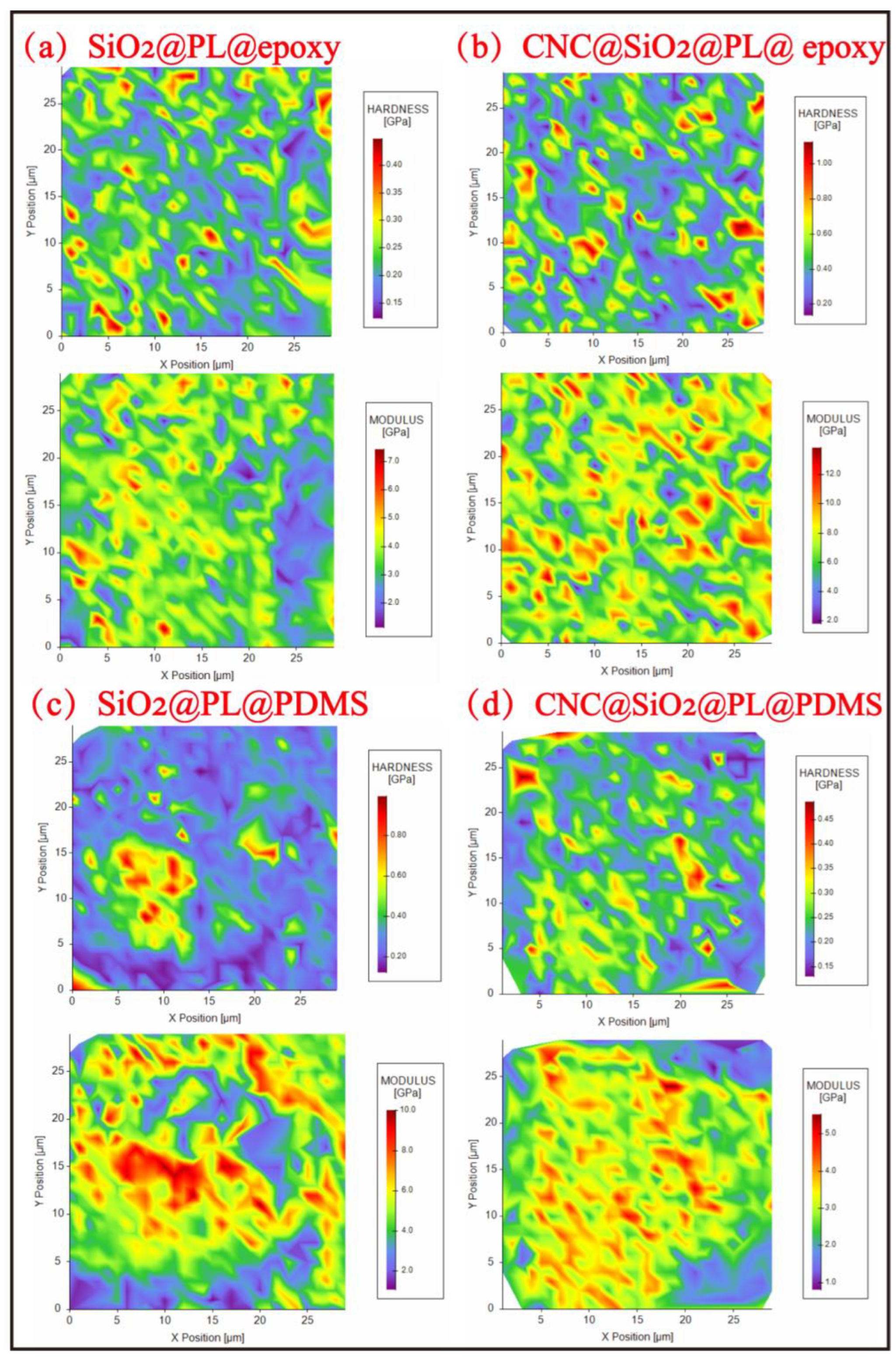
3.5. Abrasion Resistance Test Based on Nanoindentation Analysis

The methods to improve the mechanical properties of superhydrophobic coatings include sandpaper abrasion, sand free-fall impaction, cutting by a knife, etc. Among them, sandpaper abrasion is the one currently thought to be more able to imitate the destruction process of external forces, as well as comprehensive, convenient, and common methods [44]. As shown in Figure 7a, the SiO2@PL@PDMS coating could resist 27 abrasion cycles and show a gradual decrease of WCAs and increase of SAs during the sandpaper abrasion, resulting in the loss of superhydrophobic properties with the WCA of only 149.3°. The destruction by sandpaper led to the collapse of the rough structure of the coating and even the direct peeling of the coating, which would bring about the increased actual area between the water droplets and the coating surface and even the exposed hydrophilic area, thus increasing the adhesion of water droplets. That was the embodiment of the reducing WCAs and increasing SAs. It could be seen that the introduced CNC greatly improved the abrasion resistance of the superhydrophobic coating, and the abrasion cycles were up to 37 times in the CNC@SiO2@PL@PDMS coating. Compared with the SiO2@PL@PDMS coating, the CNC@SiO2@PL@PDMS coating benefited from the high crystallinity of CNC, which played a stable role in connecting the SiO2 particles together and made them difficult to erase in the abrasion process. When epoxy resin was taken as the adhesive, it could be also seen that the abrasion cycles of the coating with and without CNC were 22 and 31 times, respectively, which was a little worse than that of the coating with PDMS as the adhesive. This was determined by the properties of the adhesive. It was found that, in our previous research [31], the soft surface (PDMS) could be deformed under the external force during the abrasion process to offset part of the impact and have a certain degree of protection on the microstructure, but the hard surface (epoxy resin) could not.
The sandpaper abrasion test could visually show the mechanical strength of superhydrophobic coatings [44], but the result of this method was closely related to the grit size of the sandpaper. In the process of abrasion, the external force on the sample was asymmetrical, and the sandpaper incompletely contacted the coating surface. This might result in damage to only the local microstructure. This could not be mistaken for a loss of superhydrophobic properties. Therefore, to improve the shortcomings of the test methods above and to further determine the enhancement effect of the rod-bead rough structure constructed by the introduced CNC in the superhydrophobic coatings, nanomechanics analysis for the coatings was performed by NI mapping here. In the nanoindentation test, there was a small probe dotting the microstructure, and the stability degree of the microstructure was reflected according to the obtained nanoindentation images, so as to judge the mechanical strength of the coating.
As shown in Figure 8, the Er and H cartographies of the coatings obtained by NI mapping demonstrate the significant role of CNC in elevating the mechanical performance of the coatings. When epoxy resin was used as the adhesive, the average Er and H for the coating without CNC were 5.53 and 0.34 GPa, respectively (Figure 8a). The obtained Er and H cartographies also indicated the uneven distribution of the mechanical performance, leading to the in-prior stress concentration when subjected to abrasion. The added CNC to the coating, however, clearly improved the mechanical performance, as illustrated in Figure 8b. It could be observed that the average Er and H elevated to 8.75 and 0.83 GPa, respectively. Moreover, compared with the one without CNC, the uniform distribution of the mechanical performance in the coating with CNC enabled better stress resistance.
Changing the adhesive to PDMS could also lead to the variation in the mechanical performance of the coatings. Yet the significant role of CNC in elevating the mechanical performance was still obvious. As displayed in Figure 8c, the average Er and H for the coating without CNC were 5.05 and 0.38 GPa, respectively. The existence of CNC promoted the formation of a 3D inner-network in the coating with PDMS, elevating the average Er and H to 8.3 and 0.47 GPa, respectively (Figure 8c,d). NI analysis demonstrated that the mechanical performance of the superhydrophobic coatings could be improved by CNC, which was beneficial to elevate the abrasion resistance by promoting the 3D inner-network of the coatings and forming a uniform distribution of mechanical performance. It could be also seen that the average Er and H of the coating with PDMS was a little lower than that of the one with epoxy resin. This was because PDMS as the adhesive had good elasticity. When the coating with PDMS was pressed into the coating by the NI probe during NI mapping, it could be able to produce good deformation and some energy dissipation occurred. Because of the energy dissipation, the coating was damaged less, which was more conducive to the protection of the rough structure of the coating with PDMS. But the epoxy resin was not, it was hard and its deformation was very small. Therefore, the rough structure on the surface of the coating with epoxy resin would be more seriously damaged. This was consistent with the result from analysis of the sandpaper abrasion process above.

4. Conclusions

In this study, CNC@SiO2@PL rods were successfully prepared by PL covering the surface of CNC@SiO2 rods formed by SiO2 in situ grown on CNC, and their hydrophobic properties were endowed by hydrophobic modifiers. A superhydrophobic coating with good abrasion resistance and UV resistance could be constructed using the modified CNC@SiO2@PL rods as the main materials and PDMS or epoxy resin as the adhesives. The WCA of the CNC@SiO2@PL coating could reach 157.4°, and the SA was only 6°. Due to the introduced CNC, SiO2 was connected in series by CNC to stabilize the microstructure. Therefore, compared with the pure SiO2@PL coating, the CNC@SiO2@PL coating was better in the abrasion resistance, resisting 37 abrasion cycles. PDMS also had a certain impact on the abrasion resistance because it could offset part of the impact force through deformation in the abrasion process. To further verify, nanoindentation tests were performed. The NI mapping results showed that the mechanical strength of the coating with CNC was better, which was consistent with the results of the macroscopic sandpaper abrasion test. In addition, the introduced PL was conducive to the improvement of UV resistance. Despite going under the super-high intensity of UV irradiation (1000 W), the superhydrophobic properties of the CNC@SiO2@PL coating remained for 8 h. Due to its good performance and simple preparation, the coating is expected to achieve real application in daily life.

Author Contributions

Conceptualization, J.H.; data curation, Z.Z. and C.R.; formal analysis, Y.S.; investigation, Y.M. and L.D.; methodology, Z.W. and Y.C.; resources, J.H. and W.Z.; writing—original draft, C.R., Z.Z. and J.H. All authors have read and agreed to the published version of the manuscript.

Funding

This work was supported by the National Natural Science Foundation of China (No. 31901246), Natural Science Foundation of Zhejiang Province (No. LY21C160002), Scientific Research Development Foundation of Zhejiang A&F University (No. KX20180107).

Institutional Review Board Statement

Not applicable.

Data Availability Statement

The data presented in this study is available on request from the corresponding author.

Acknowledgments

The authors would like to thank the National Engineering and Technology Research Center for wood-based resources provision and comprehensive use of an experimental platform in this experiment.

Conflicts of Interest

The authors declare no conflict of interest.

References

  1. Torres, L.A.Z.; Woiciechowski, A.L.; Tanobe, V.O.D.A.; Karp, S.G.; Lorenci, L.C.G.; Faulds, C.; Soccol, C.R. Lignin as a potential source of high-added value compounds: A review. J. Clean. Prod. 2020, 263, 121499. [Google Scholar] [CrossRef]
  2. Huang, D.; Li, R.; Xu, P.; Li, T.; Deng, R.; Chen, S.; Zhang, Q. The cornerstone of realizing lignin value-addition: Exploiting the native structure and properties of lignin by extraction methods. Chem. Eng. J. 2020, 402, 126237. [Google Scholar] [CrossRef]
  3. Collins, P.J.; Field, J.A.; Teunissen, P.; Dobson, A.D. Stabilization of lignin peroxidases in white rot fungi by tryptophan. Appl. Environ. Microbiol. 1997, 63, 2543–2548. [Google Scholar] [CrossRef]
  4. Xiong, F.; Han, Y.; Wang, S.; Li, G.; Qin, T.; Chen, Y.; Chu, F. Preparation and formation mechanism of size-controlled lignin nanospheres by self-assembly. Ind. Crop. Prod. 2017, 100, 146–152. [Google Scholar] [CrossRef]
  5. Gong, X.; Meng, Y.; Zhu, J.; Wang, X.; Lu, J.; Cheng, Y.; Tao, Y.; Wang, H. Construct a stable super-hydrophobic surface through acetonitrile extracted lignin and nano-silica and its application in oil-water separation. Ind. Crop. Prod. 2021, 166, 113471. [Google Scholar] [CrossRef]
  6. Huang, J.; Lyu, S.; Chen, Z.; Wang, S.; Fu, F. A facile method for fabricating robust cellulose nanocrystal/SiO2 superhydrophobic coatings. J. Colloid Interface Sci. 2018, 536, 349–362. [Google Scholar] [CrossRef] [PubMed]
  7. Cheng, Y.-T.; Rodak, D.E. Is the lotus leaf superhydrophobic? Appl. Phys. Lett. 2005, 86, 144101. [Google Scholar] [CrossRef]
  8. Latthe, S.S.; Terashima, C.; Nakata, K.; Fujishima, A. Superhydrophobic surfaces developed by mimicking hierarchical surface morphology of lotus leaf. Molecules 2014, 19, 4256–4283. [Google Scholar] [CrossRef] [PubMed]
  9. Kolyaganova, O.; Klimov, V.V.; Bryuzgin, E.V.; Le, M.D.; Kharlamov, V.O.; Bryuzgina, E.B.; Navrotsky, A.V.; Novakov, I.A. Modification of wood with copolymers based on glycidyl methacrylate and alkyl methacrylates for imparting superhydrophobic properties. J. Appl. Polym. Sci. 2022, 139, 51636. [Google Scholar] [CrossRef]
  10. Gao, H.; Jian, Y.; Yan, Y. The effects of bio-inspired micro/nano scale structures on anti-icing properties. Soft Matter 2021, 17, 447–466. [Google Scholar] [CrossRef] [PubMed]
  11. Kim, M.C.; Klages, C.P. One-step process to deposit a soft super-hydrophobic film by filamentary dielectric barrier discharge-assisted CVD using HMCTSO as a precursor. Surf. Coat. Technol. 2009, 204, 428–432. [Google Scholar] [CrossRef]
  12. Yang, H.; Pi, P.; Cai, Z.-Q.; Wen, X.; Wang, X.; Cheng, J.; Yang, Z.-R. Facile preparation of super-hydrophobic and super-oleophilic silica film on stainless steel mesh via sol–gel process. Appl. Surf. Sci. 2010, 256, 4095–4102. [Google Scholar] [CrossRef]
  13. Sharma, D.K.; Kumar, R.; Avasthi, D.K.; Sikarwar, B.S. Self assembly of super-hydrophobic nanotextured methyl functionalized silica on copper and aluminium surfaces for moist air condensation. Colloids Surf. A Physicochem. Eng. Asp. 2020, 605, 125379. [Google Scholar] [CrossRef]
  14. Li, D.-W.; Wang, H.-Y.; Liu, Y.; Wei, D.-S.; Zhao, Z.-X. Large-scale fabrication of durable and robust super-hydrophobic spray coatings with excellent repairable and anti-corrosion performance. Chem. Eng. J. 2019, 367, 169–179. [Google Scholar] [CrossRef]
  15. Li, S.; Lin, M.M.; Toprak, M.S.; Kim, D.K.; Muhammed, M. Nanocomposites of polymer and inorganic nanoparticles for optical and magnetic applications. Nanotechnol. Rev. 2010, 1, 5214. [Google Scholar] [CrossRef]
  16. Ten, E.; Vermerris, W. Recent developments in polymers derived from industrial lignin. J. Appl. Polym. Sci. 2015, 132, 24. [Google Scholar] [CrossRef]
  17. Simpson, J.T.; Hunter, S.R.; Aytug, T. Superhydrophobic materials and coatings: A review. Rep. Prog. Phys. 2015, 78, 086501. [Google Scholar] [CrossRef]
  18. Li, M.; Li, Y.; Xue, F.; Jing, X. A robust and versatile superhydrophobic coating: Wear-resistance study upon sandpaper abrasion. Appl. Surf. Sci. 2019, 480, 738–748. [Google Scholar] [CrossRef]
  19. Lim, S.; Kim, S.; Ahn, K.H.; Lee, S.J. The effect of binders on the rheological properties and the microstructure formation of lithium-ion battery anode slurries. J. Power Sources 2015, 299, 221–230. [Google Scholar] [CrossRef]
  20. Latif, M.; Jiang, Y.; Kumar, B.; Cho, H.C.; Song, J.M.; Kim, J. Three-dimensional printing of highly crosslinked and concentrated nanocellulose for environmentally friendly structural applications. ACS Appl. Nano Mater. 2022, 5, 5680–5687. [Google Scholar] [CrossRef]
  21. Latif, M.; Jiang, Y.; Kumar, B.; Song, J.M.; Cho, H.C.; Kim, J. High content nanocellulose 3D-printed and esterified structures with strong interfacial adhesion, high mechanical properties, and shape fidelity. Adv. Mater. Interfaces 2022, 9, 2200280. [Google Scholar] [CrossRef]
  22. Xu, G.; Wang, H.; Zhu, H. Rheological properties and anti-aging performance of asphalt binder modified with wood lignin. Constr. Build. Mater. 2017, 151, 801–808. [Google Scholar] [CrossRef]
  23. Sugiarto, S.; Leow, Y.; Tan, C.L.; Wang, G.; Kai, D. How far is lignin from being a biomedical material? Bioact. Mater. 2022, 8, 71–94. [Google Scholar] [CrossRef] [PubMed]
  24. Meng, C.; Liu, F.; Li, Z.; Yu, C. The cellulose protection agent used in the oxidation degumming of ramie. Text. Res. J. 2016, 86, 1109–1118. [Google Scholar] [CrossRef]
  25. Krakhmalev, P.; Rodil, T.A.; Bergström, J. Influence of microstructure on the abrasive edge wear of WC–Co hardmetals. Wear 2007, 263, 240–245. [Google Scholar] [CrossRef]
  26. Gong, L.; Wu, H.; Shan, X.; Li, Z. Facile fabrication of phosphorylated alkali lignin microparticles for efficient adsorption of antibiotics and heavy metal ions in water. J. Environ. Chem. Eng. 2021, 9, 106574. [Google Scholar] [CrossRef]
  27. Xiong, W.; Yang, D.; Zhong, R.; Li, Y.; Zhou, H.; Qiu, X. Preparation of lignin-based silica composite submicron particles from alkali lignin and sodium silicate in aqueous solution using a direct precipitation method. Ind. Crop. Prod. 2015, 74, 285–292. [Google Scholar] [CrossRef]
  28. Wu, Y.; Zhang, H.; Yang, L.; Wang, S.; Meng, Y. Understanding the effect of extractives on the mechanical properties of the waterborne coating on wood surface by nanoindentation 3D mapping. J. Mater. Sci. 2021, 56, 1401–1412. [Google Scholar] [CrossRef]
  29. Xu, C.; Cao, Y.; Chen, H.; Nie, Y.; Meng, Y.; Wu, Q.; Wang, S. Large-scale and high-resolution visualization of static mechanical properties of wood-adhesive interphase utilizing nanoindentation mapping. Wood Sci. Technol. 2022, 56, 1029–1045. [Google Scholar] [CrossRef]
  30. Oliver, W.C.; Pharr, G.M. An improved technique for determining hardness and elastic modulus using load and displacement sensing indentation experiments. J. Mater. Res. 1992, 7, 1564–1583. [Google Scholar] [CrossRef]
  31. Huang, J.; Li, M.; Ren, C.; Huang, W.; Miao, Y.; Wu, Q.; Wang, S. Construction of HLNPs/Fe3O4 based superhydrophobic coating with excellent abrasion resistance, UV resistance, flame retardation and oil absorbency. J. Environ. Chem. Eng. 2023, 11, 109046. [Google Scholar] [CrossRef]
  32. Prieur, B.; Meub, M.; Wittemann, M.; Klein, R.; Bellayer, S.; Fontaine, G.; Bourbigot, S. Phosphorylation of lignin to flame retard acrylonitrile butadiene styrene (ABS). Polym. Degrad. Stab. 2016, 127, 32–43. [Google Scholar] [CrossRef]
  33. Cui, J.; Xie, A.; Zhou, S.; Liu, S.; Wang, Q.; Wu, Y.; Meng, M.; Lang, J.; Zhou, Z.; Yan, Y. Development of composite membranes with irregular rod-like structure via atom transfer radical polymerization for efficient oil-water emulsion separation. J. Colloid Interface Sci. 2019, 533, 278–286. [Google Scholar] [CrossRef] [PubMed]
  34. Kumar, B.; Roy, S.; Agumba, D.O.; Pham, D.H.; Kim, J. Effect of bio-based derived epoxy resin on interfacial adhesion of cellulose film and applicability towards natural jute fiber-reinforced composites. Int. J. Biol. Macromol. 2022, 222, 1304–1313. [Google Scholar] [CrossRef] [PubMed]
  35. Varma, H.; Babu, S.S. Synthesis of calcium phosphate bioceramics by citrate gel pyrolysis method. Ceram. Int. 2005, 31, 109–114. [Google Scholar] [CrossRef]
  36. Xie, J.; Hu, J.; Lin, X.; Fang, L.; Wu, F.; Liao, X.; Luo, H.; Shi, L. Robust and anti-corrosive PDMS/SiO2 superhydrophobic coatings fabricated on magnesium alloys with different-sized SiO2 nanoparticles. Appl. Surf. Sci. 2018, 457, 870–880. [Google Scholar] [CrossRef]
  37. Li, Y.; Men, X.; Zhu, X.; Ge, B.; Chu, F.; Zhang, Z. One-step spraying to fabricate nonfluorinated superhydrophobic coatings with high transparency. J. Mater. Sci. 2016, 51, 2411–2419. [Google Scholar] [CrossRef]
  38. Xiong, M.; Ren, Z.; Liu, W. Fabrication of UV-resistant and superhydrophobic surface on cotton fabric by functionalized polyethyleneimine/SiO2 via layer-by-layer assembly and dip-coating. Cellulose 2019, 26, 8951–8962. [Google Scholar] [CrossRef]
  39. Egorov, A.A.; Fedotov, A.Y.; Mironov, A.V.; Komlev, V.S.; Popov, V.; Zobkov, Y.V. 3D printing of mineral–polymer bone substitutes based on sodium alginate and calcium phosphate. Beilstein. J. Nanotech. 2016, 7, 1794–1799. [Google Scholar] [CrossRef]
  40. Kaur, R.; Bhardwaj, S.K.; Chandna, S.; Kim, K.-H.; Bhaumik, J. Lignin-based metal oxide nanocomposites for UV protection applications: A review. J. Clean. Prod. 2021, 317, 128300. [Google Scholar] [CrossRef]
  41. Li, M.; Huang, W.; Ren, C.; Wu, Q.; Wang, S.; Huang, J. Preparation of lignin nanospheres based superhydrophobic surfaces with good robustness and long UV resistance. RSC Adv. 2022, 12, 11517–11525. [Google Scholar] [CrossRef] [PubMed]
  42. Ou, J.; Zhao, G.; Wang, F.; Li, W.; Lei, S.; Fang, X.; Siddiqui, A.R.; Xia, Y.; Amirfazli, A. Durable superhydrophobic wood via one-step immersion in composite silane solution. ACS Omega 2021, 6, 7266–7274. [Google Scholar] [CrossRef] [PubMed]
  43. Zhang, J.; Zhang, L.; Gong, X. Large-scale spraying fabrication of robust fluorine-free superhydrophobic coatings based on dual-sized silica particles for effective antipollution and strong buoyancy. Langmuir 2021, 37, 6042–6051. [Google Scholar] [CrossRef]
  44. Yang, Y.; Huang, W.; Guo, Z.; Zhang, S.; Wu, F.; Huang, J.; Yang, H.; Zhou, Y.; Xu, W.; Gu, S. Robust fluorine-free colorful superhydrophobic PDMS/NH2-MIL-125 (Ti)@ cotton fabrics for improved ultraviolet resistance and efficient oil–water separation. Cellulose 2019, 26, 9335–9348. [Google Scholar] [CrossRef]
Figure 1. Preparation process demonstration and forming mechanism of CNC@SiO2@PL-based superhydrophobic wood, and possible chemical reactions during preparation.
Polymers 15 00933 g001
Figure 2. TEM images of (a) CNC@SiO2, (b) CNC@SiO2@PL, (c) modified CNC@SiO2@PL@PDMS coating; SEM images of (d) pure wood, (e) SiO2, (f) CNC@SiO2, (g) CNC@SiO2@PL, (h) CNC@SiO2@PL@PDMS coated woods. The illustrations in red box are the corresponding high magnification images.
Polymers 15 00933 g002
Figure 3. FTIR spectra of (a) lignin (L), PL and CNC@SiO2 and CNC@SiO2@PL rods and (b) the modified CNC@SiO2@PL and CNC@SiO2@PL@PDMS coatings; Local FTIR spectra of (a1) C-O bonds in L and (a2) C-O-Cbonds in L and PL.
Polymers 15 00933 g003
Figure 4. XPS spectra of (a) CNC@SiO2, CNC@SiO2@PL, modified CNC@SiO2@PL and CNC@SiO2@PL@PDMS coatings, (b) P2p spectra of unmodified CNC@SiO2@PL, (c,d) O1s spectra of unmodified CNC@SiO2@PL and CNC@SiO2@PL@PDMS coatings. Local enlarged XPS spectra of (a1, a2) elements P in CNC@SiO2 and CNC@SiO2@PL rods.
Polymers 15 00933 g004
Figure 5. The droplets state on the surface of different samples: (a) pure wood, (b) SiO2, (c) CNC@SiO2@PL coatings; modified (d) CNC@SiO2@PL, (e) SiO2@PL, and (f) CNC@SiO2@PL@PDMS coatings.
Polymers 15 00933 g005
Figure 6. Change curves of WCAs and SAs on the modified CNC@SiO2, CNC@SiO2@PL, CNC@SiO2@PL@PDMS coatings with time of exposure to UV radiation of (ac)15 W or (df) 1000 W.
Polymers 15 00933 g006
Figure 7. Change curves of WCAs and SAs on the modified (a) SiO2@PL@PDMS and (b) CNC@SiO2@PL@PDMS coatings, (c) SiO2@PL@epoxy and (d) CNC@SiO2@PL@epoxy coatings.
Polymers 15 00933 g007
Figure 8. Nanoindentation analysis of different samples: (a) SiO2@PL@epoxy, (b) CNC@SiO2@PL epoxy, (c) SiO2@PL@PDMS and (d) CNC@SiO2@PL@PDMS coatings.
Polymers 15 00933 g008
Table 1. Atomic ratio of elements in the CNC@SiO2 coating, CNC@SiO2@PL coatings before and after modification and modified CNC@SiO2@PL@PDMS coatings.
SamplesAtomic Percent (%)
CNSiOP
CNC@SiO26.040.6928.3264.85-
CNC@SiO2@PL28.883.5713.851.762
Modified CNC@SiO2@PL48.080.5517.7633.140.47
Modified CNC@SiO2@PL@PDMS51.560.6114.8531.731.26
Table 2. Comparison of different superhydrophobic coatings for WCAs.
Superhydrophobic CoatingsWCARef.
PDMS/SiO2 coating153.6°[36]
(PEI-H/SiO2)3@HDTMS coating154°[37]
PTMS-SiO2 coating158.5°[38]
CNC@SiO2@PL@PDMS coating157.4°This work
Table 3. Comparison of different superhydrophobic coatings for UV resistance.
Superhydrophobic CoatingsUV Resistance TimeUV PowerRef.
PTMS-SiO2 coatings10 h8 W[38]
The composite silane coating200 h60 W[42]
SiO2 @ EP@ PDMS coating2 h1000 W[43]
CNC@SiO2@PL@PDMS coating8 (240) h1000 (15) WThis work
Disclaimer/Publisher’s Note: The statements, opinions and data contained in all publications are solely those of the individual author(s) and contributor(s) and not of MDPI and/or the editor(s). MDPI and/or the editor(s) disclaim responsibility for any injury to people or property resulting from any ideas, methods, instructions or products referred to in the content.

