


Analysis of Shielding Effectiveness against Electromagnetic Interference (EMI) for Metal-Coated Polymeric Materials
 ,
,
Abstract
:1. Introduction
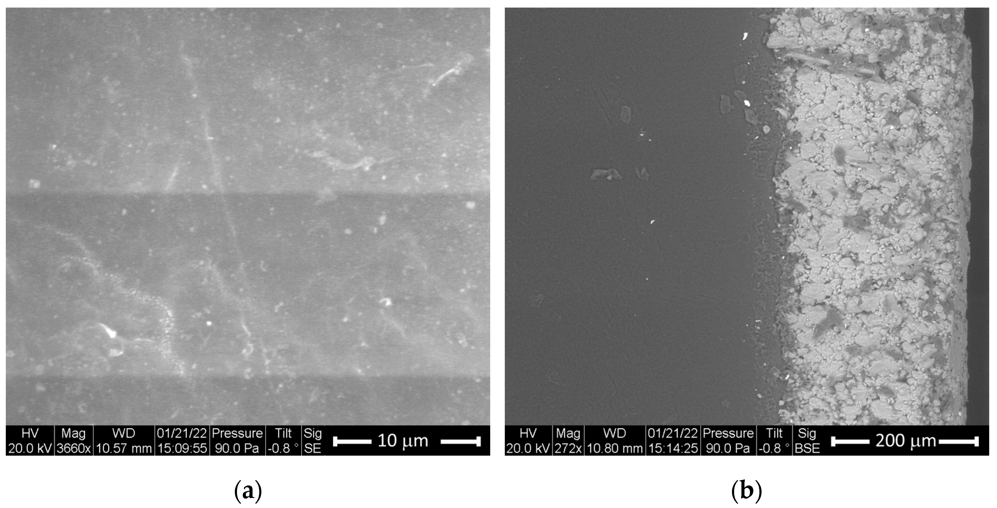
2. Experiments
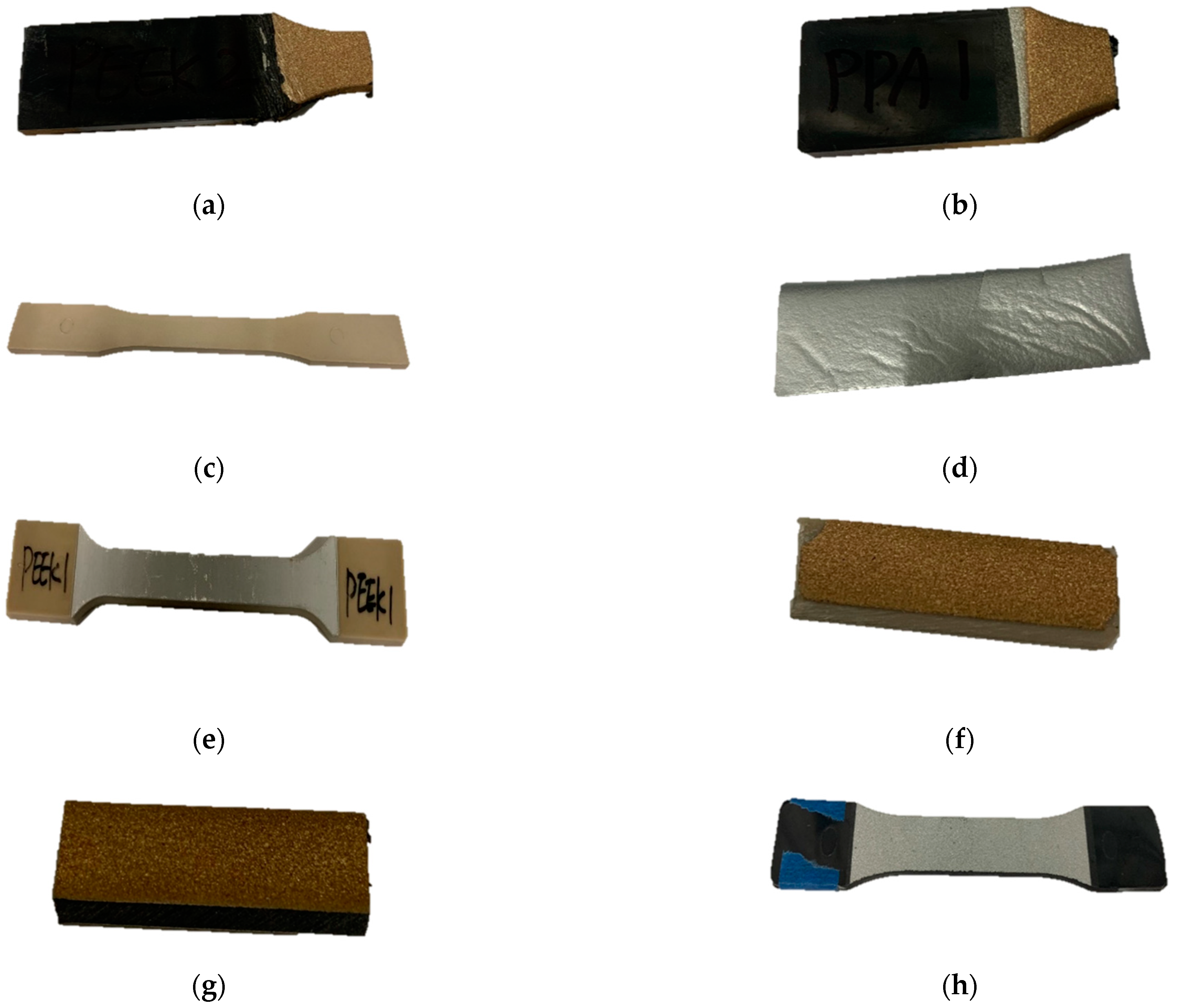
2.1. Materials
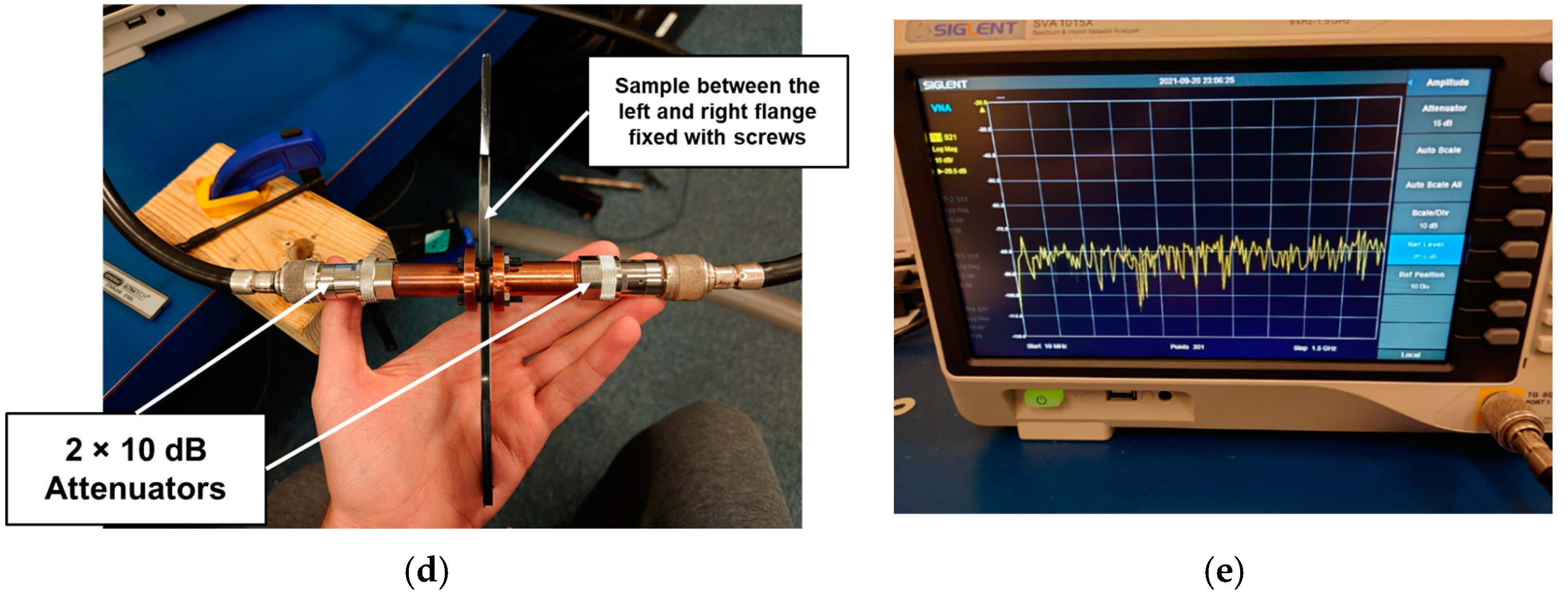
2.2. Experimental Setup
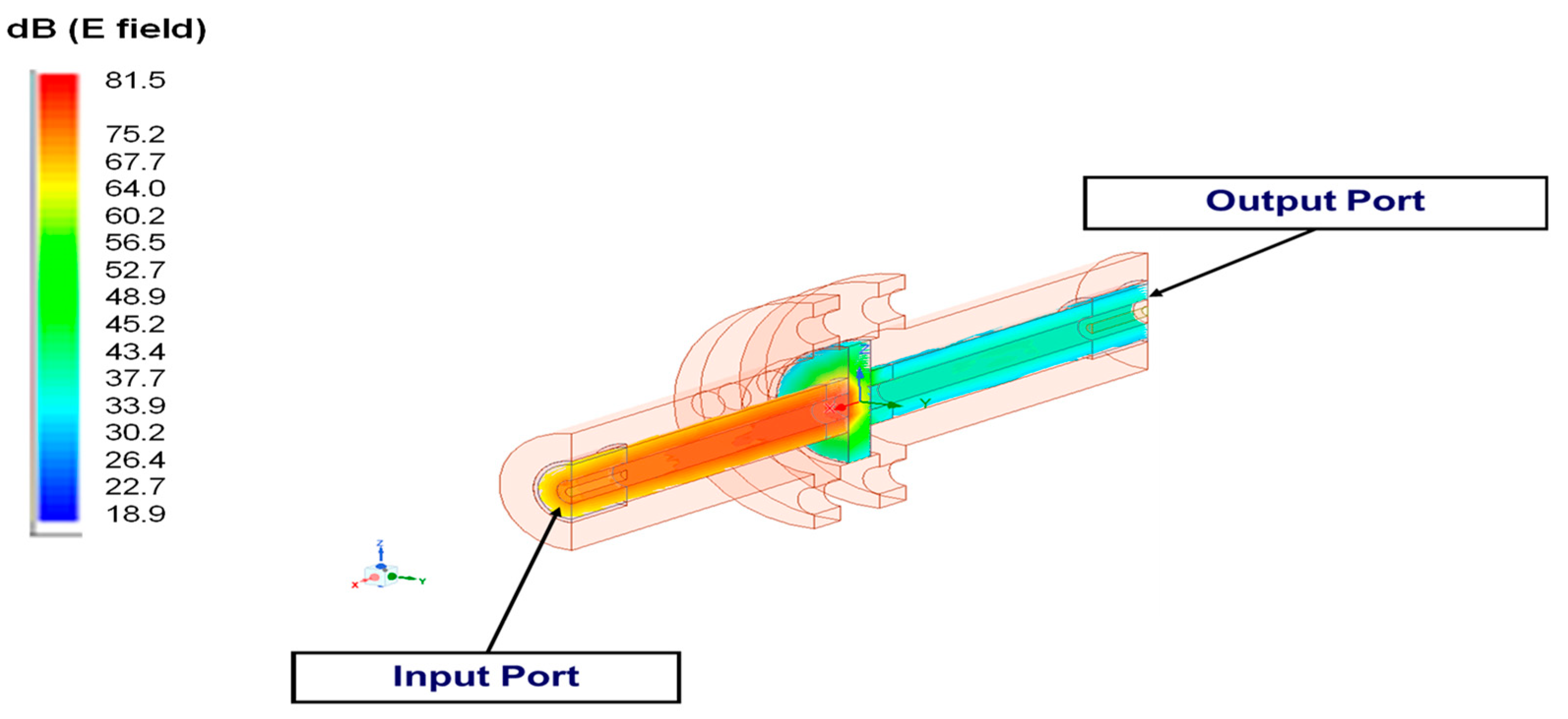
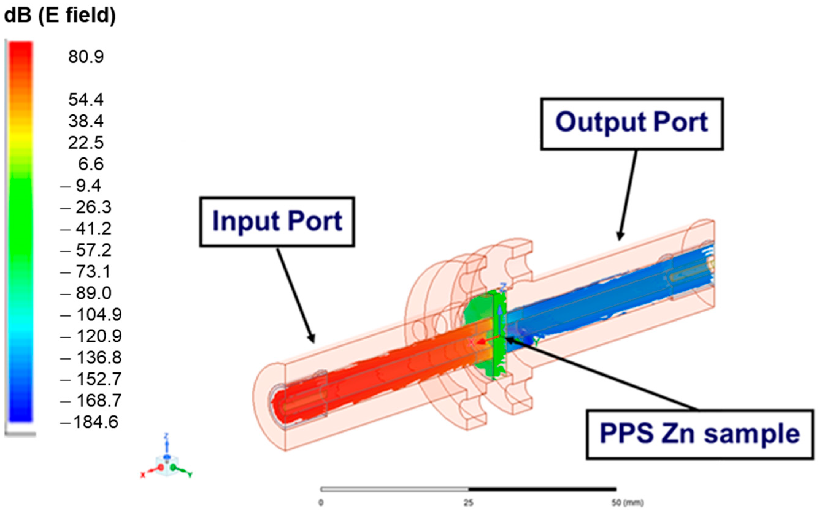
2.3. Simulation Using ANSYS HFSS
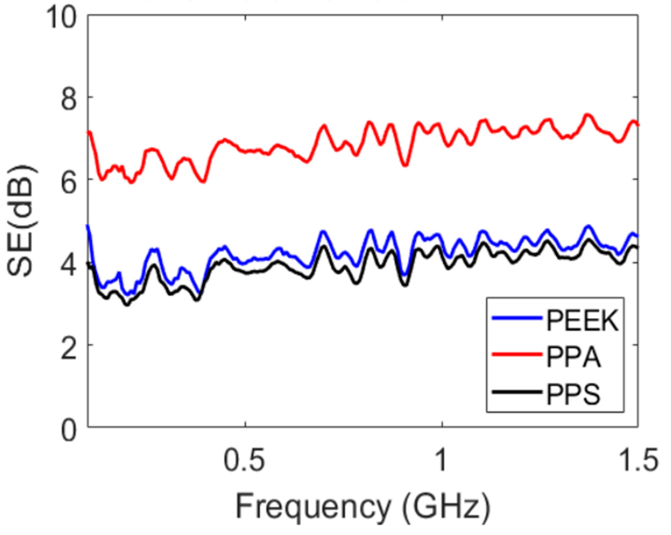
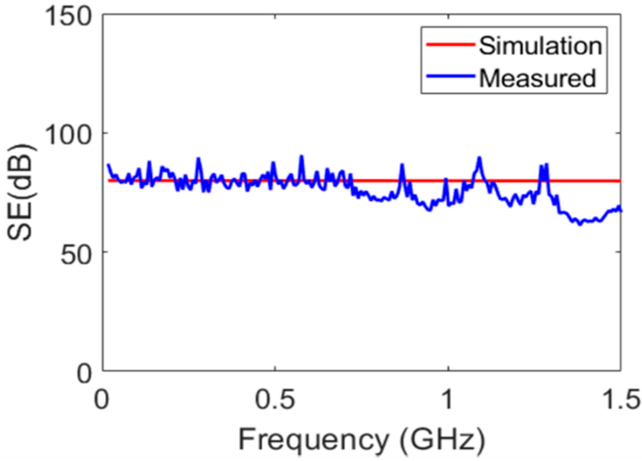
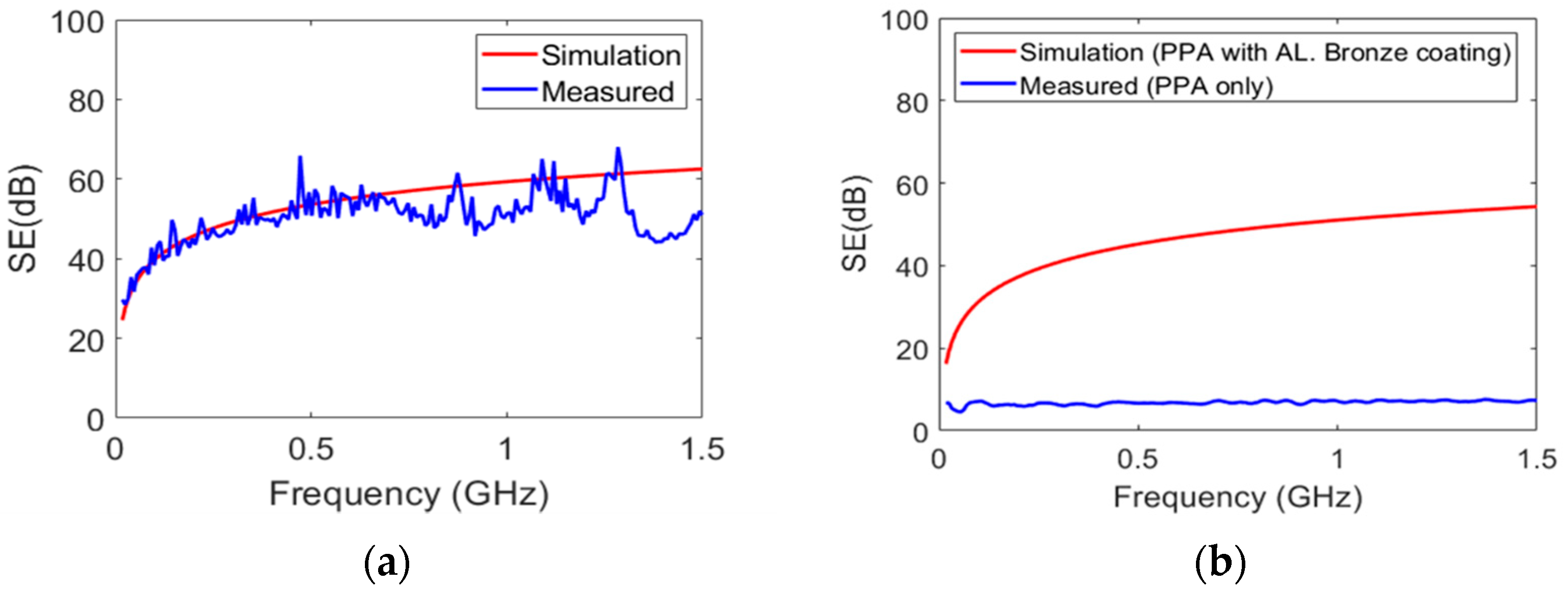
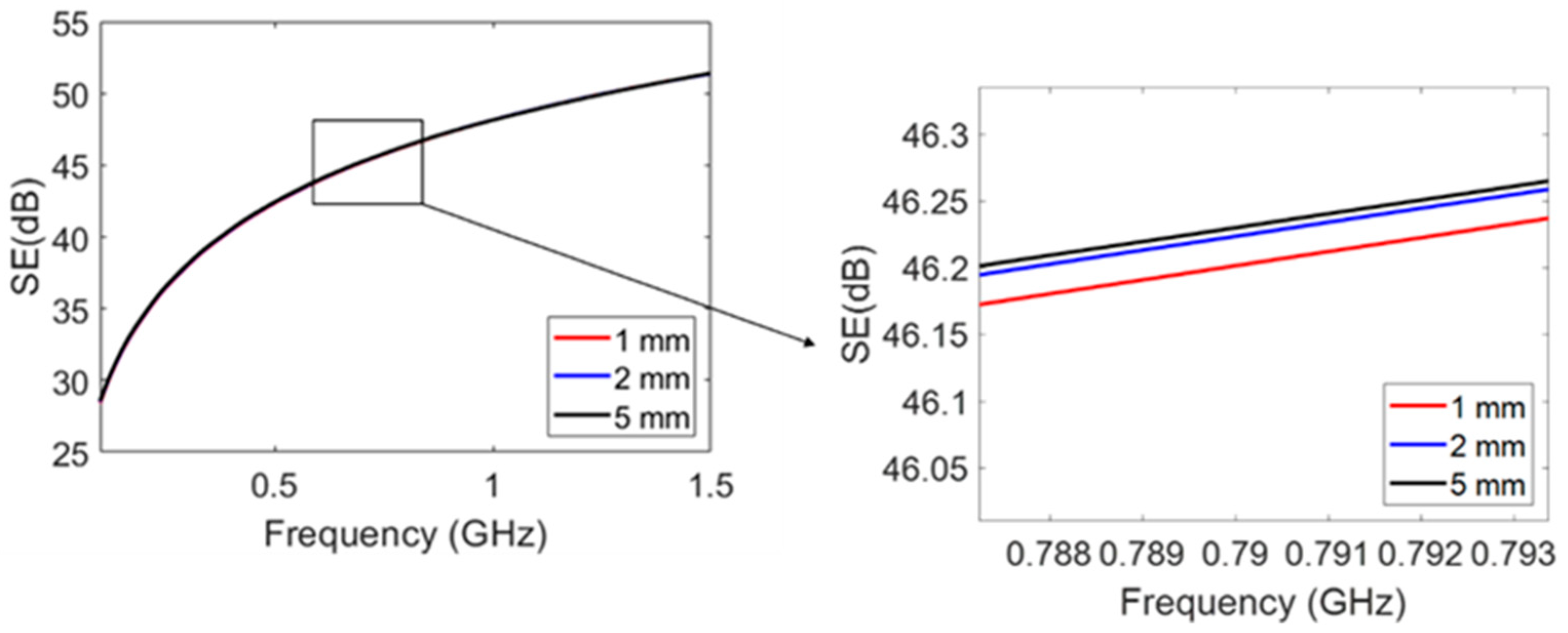
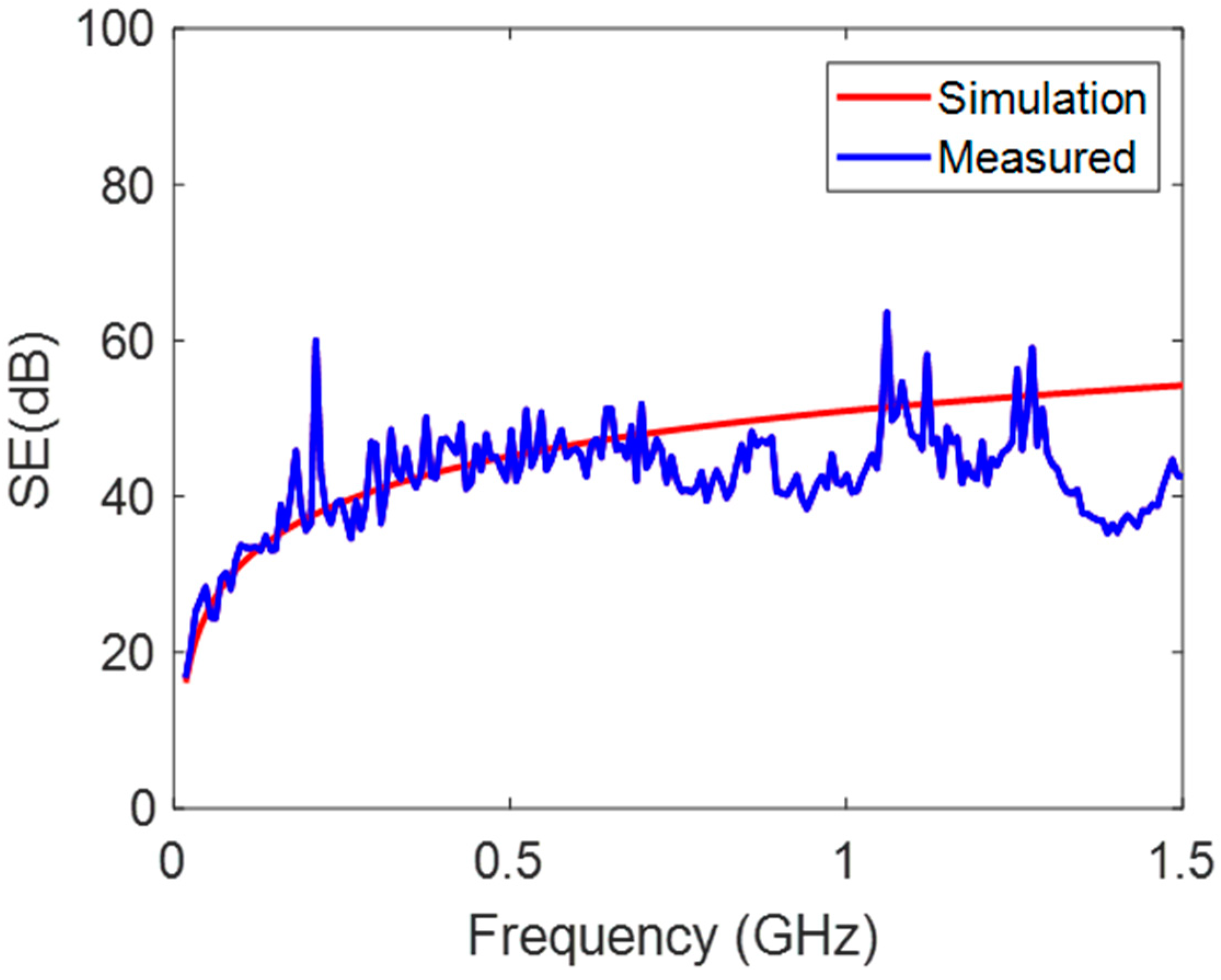
3. Results and Discussion
ANSYS Simulation
4. Conclusions
Supplementary Materials
Author Contributions
Funding
Institutional Review Board Statement
Informed Consent Statement
Data Availability Statement
Conflicts of Interest
References
- Han, Y.; Kumon, R.; Mostafavi Yazdi, S.J.; Zhu, N.; Afshar, A.; Baqersad, J. Nondestructive evaluation of carbon-fiber composites using digital image correlation, acoustic emission, and optical based modal analysis. Wind. Eng. 2022, 46, 1618–1628. [Google Scholar] [CrossRef]
- Salifu, S.; Desai, D.; Ogunbiyi, O.; Mwale, K. Recent development in the additive manufacturing of polymer-based composites for automotive structures—A review. Int. J. Adv. Manuf. Technol. 2022, 119, 6877–6891. [Google Scholar] [CrossRef]
- Kim, K.; Huh, J.Y.; Hong, Y.C. Direct coating of copper nanoparticles on flexible substrates from copper precursors using underwater plasma and their EMI performance. Mater. Sci. Eng. B 2021, 265, 114995. [Google Scholar] [CrossRef]
- Schmitz, D.; Ecco, L.; Dul, S.; Pereira, E.; Soares, B.; Barra, G.; Pegoretti, A. Electromagnetic interference shielding effectiveness of ABS carbon-based composites manufactured via fused deposition modelling. Mater. Today Commun. 2018, 15, 70–80. [Google Scholar] [CrossRef]
- Younes, H.; Mansoori, M.; Chaturvedi, P.; Li, R.; Almahmoud, S.; Lee, S.-E.; Koo, T.M.; Kim, Y.K.; Choi, D. Magnetic spinel manganese ferrite nanocrystal carbon nanotube thin mats with improved electromagnetic shielding performance. J. Nanopart. Res. 2022, 24, 258. [Google Scholar] [CrossRef]
- Chung, D.D. Materials for electromagnetic interference shielding. Mater. Chem. Phys. 2020, 255, 123587. [Google Scholar] [CrossRef]
- Liao, S.-Y.; Wang, X.-Y.; Li, X.-M.; Wan, Y.-J.; Zhao, T.; Hu, Y.-G.; Zhu, P.-L.; Sun, R.; Wong, C.-P. Flexible liquid metal/cellulose nanofiber composites film with excellent thermal reliability for highly efficient and broadband EMI shielding. Chem. Eng. J. 2021, 422, 129962. [Google Scholar] [CrossRef]
- Kong, D.; Li, J.; Guo, A.; Xiao, X. High temperature electromagnetic shielding shape memory polymer composite. Chem. Eng. J. 2021, 408, 127365. [Google Scholar] [CrossRef]
- Park, G.; Kim, S.; Park, G.-K.; Lee, N. Influence of carbon fiber on the electromagnetic shielding effectiveness of high-performance fiber-reinforced cementitious composites. J. Build. Eng. 2021, 35, 101982. [Google Scholar] [CrossRef]
- Ryu, S.H.; Han, Y.K.; Kwon, S.J.; Kim, T.; Jung, B.M.; Lee, S.-B.; Park, B. Absorption-dominant, low reflection EMI shielding materials with integrated metal mesh/TPU/CIP composite. Chem. Eng. J. 2022, 428, 131167. [Google Scholar] [CrossRef]
- Kozak, N.; Matzui, L.; Vovchenko, L.; Kosyanchuk, L.; Oliynyk, V.; Antonenko, O.; Nesin, S.; Gagolkina, Z. Influence of coordination complexes of transition metals on EMI-shielding properties and permeability of polymer blend/carbon nanotube/nickel composites. Compos. Sci. Technol. 2020, 200, 108420. [Google Scholar] [CrossRef]
- Wilson, R.; George, G.; Joseph, K. An introduction to materials for potential EMI shielding applications: Status and future. In Materials for Potential EMI Shielding Applications; Elsevier: Amsterdam, The Netherlands, 2020; pp. 1–8. [Google Scholar] [CrossRef]
- Markham, D. Shielding: Quantifying the shielding requirements for portable electronic design and providing new solutions by using a combination of materials and design. Mater. Des. 1999, 21, 45–50. [Google Scholar] [CrossRef]
- Chung, D. Electromagnetic interference shielding effectiveness of carbon materials. Carbon 2001, 39, 279–285. [Google Scholar] [CrossRef]
- Hong, Y.; Lee, C.; Jeong, C.; Sim, J.; Kim, K.; Joo, J.; Kim, M.; Lee, J.; Jeong, S.; Byun, S. Electromagnetic interference shielding characteristics of fabric complexes coated with conductive polypyrrole and thermally evaporated Ag. Curr. Appl. Phys. 2001, 1, 439–442. [Google Scholar] [CrossRef]
- Yuping, D.; Shunhua, L.; Hongtao, G. Investigation of electrical conductivity and electromagnetic shielding effectiveness of polyaniline composite. Sci. Technol. Adv. Mater. 2005, 6, 513–518. [Google Scholar] [CrossRef]
- Chen, X.; Liu, L.; Liu, J.; Pan, F. Microstructure, electromagnetic shielding effectiveness and mechanical properties of Mg–Zn–Y–Zr alloys. Mater. Des. (1980–2015) 2015, 65, 360–369. [Google Scholar] [CrossRef]
- Kasgoz, A.; Korkmaz, M.; Alanalp, M.B.; Durmus, A. Effect of processing method on microstructure, electrical conductivity and electromagnetic wave interference (EMI) shielding performance of carbon nanofiber filled thermoplastic polyurethane composites. J. Polym. Res. 2017, 24, 1–11. [Google Scholar] [CrossRef]
- Narasimman, R.; Vijayan, S.; Prabhakaran, K. Graphene-reinforced carbon composite foams with improved strength and EMI shielding from sucrose and graphene oxide. J. Mater. Sci. 2015, 50, 8018–8028. [Google Scholar] [CrossRef]
- Valente, R.; De Ruijter, C.; Vlasveld, D.; Van Der Zwaag, S.; Groen, P. Setup for EMI Shielding Effectiveness Tests of Electrically Conductive Polymer Composites at Frequencies up to 3.0 GHz. IEEE Access 2017, 5, 16665–16675. [Google Scholar] [CrossRef]
- Munalli, D.; Dimitrakis, G.; Chronopoulos, D.; Greedy, S.; Long, A. Electromagnetic shielding effectiveness of carbon fibre reinforced composites. Compos. Part B Eng. 2019, 173, 106906. [Google Scholar] [CrossRef]
- Wanasinghe, D.; Aslani, F.; Ma, G. Electromagnetic shielding properties of carbon fibre reinforced cementitious composites. Constr. Build. Mater. 2020, 260, 120439. [Google Scholar] [CrossRef]
- Yao, Y.; Jin, S.; Zou, H.; Li, L.; Ma, X.; Lv, G.; Gao, F.; Lv, X.; Shu, Q. Polymer-based lightweight materials for electromagnetic interference shielding: A review. J. Mater. Sci. 2021, 56, 6549–6580. [Google Scholar] [CrossRef]
- Vasquez, H.; Espinoza, L.; Lozano, K.; Foltz, H.; Yang, S. Simple device for electromagnetic interference shielding effectiveness measurement. IEEE EMC Soc. Newsl. 2009, 220, 62–68. [Google Scholar]
- Wang, W.; Hua, D.; Zhou, Q.; Li, S.; Eder, S.J.; Shi, J.; Wang, Z.; Wang, H.; Liu, W. Effect of a water film on the material removal behavior of Invar during chemical mechanical polishing. Appl. Surf. Sci. 2023, 616, 156490. [Google Scholar] [CrossRef]
- Jia, Q.; He, W.; Hua, D.; Zhou, Q.; Du, Y.; Ren, Y.; Lu, Z.; Wang, H.; Zhou, F.; Wang, J. Effects of structure relaxation and surface oxidation on nanoscopic wear behaviors of metallic glass. Acta Mater. 2022, 232, 117934. [Google Scholar] [CrossRef]
- Ye, W.; Xie, M.; Huang, Z.; Wang, H.; Zhou, Q.; Wang, L.; Chen, B.; Wang, H.; Liu, W. Microstructure and tribological properties of in-situ carbide/CoCrFeNiMn high entropy alloy composites synthesized by flake powder metallurgy. Tribol. Int. 2023, 181, 108295. [Google Scholar] [CrossRef]
- Ma, L.; Hamidinejad, M.; Wei, L.; Zhao, B.; Park, C.B. Absorption-dominant EMI shielding polymer composite foams: Microstructure and geometry optimization. Mater. Today Phys. 2023, 30, 100940. [Google Scholar] [CrossRef]
- Jain, H.; Kumar, R.; Gupta, G.; Mondal, D. Microstructure, mechanical and EMI shielding performance in open cell austenitic stainless steel foam made through PU foam template. Mater. Chem. Phys. 2020, 241, 122273. [Google Scholar] [CrossRef]


| Material | Conductivity (S/M) | Dielectric Constant | Thickness (MM) |
|---|---|---|---|
| Aluminum | 3.8 × 10⁷ | 1 | 0.250 |
| Zinc | 1.2 × 10⁷ | 1 | 0.050 |
| PPA GF | 1.5 × 10⁻¹³ | 4.3 | 3.960 |
| PPS | 4.5 × 10⁻¹⁴ | 3.0 | 3.290 |
| PEEK | 4.9 × 10⁻¹⁴ | 3.3 | 4.070 |
| Al-Bronze | 1.368 × 10⁷ | 1 | 0.200 |
Disclaimer/Publisher’s Note: The statements, opinions and data contained in all publications are solely those of the individual author(s) and contributor(s) and not of MDPI and/or the editor(s). MDPI and/or the editor(s) disclaim responsibility for any injury to people or property resulting from any ideas, methods, instructions or products referred to in the content. |
© 2023 by the authors. Licensee MDPI, Basel, Switzerland. This article is an open access article distributed under the terms and conditions of the Creative Commons Attribution (CC BY) license (https://creativecommons.org/licenses/by/4.0/).
Share and Cite
Mostafavi Yazdi, S.J.; Lisitski, A.; Pack, S.; Hiziroglu, H.R.; Baqersad, J. Analysis of Shielding Effectiveness against Electromagnetic Interference (EMI) for Metal-Coated Polymeric Materials. Polymers 2023, 15, 1911. https://doi.org/10.3390/polym15081911
Mostafavi Yazdi SJ, Lisitski A, Pack S, Hiziroglu HR, Baqersad J. Analysis of Shielding Effectiveness against Electromagnetic Interference (EMI) for Metal-Coated Polymeric Materials. Polymers. 2023; 15(8):1911. https://doi.org/10.3390/polym15081911
Chicago/Turabian StyleMostafavi Yazdi, Seyed Jamaleddin, Andrej Lisitski, Seongchan Pack, Huseyin R. Hiziroglu, and Javad Baqersad. 2023. "Analysis of Shielding Effectiveness against Electromagnetic Interference (EMI) for Metal-Coated Polymeric Materials" Polymers 15, no. 8: 1911. https://doi.org/10.3390/polym15081911