Towards Extrusion of Ionomers to Process Fuel Cell Membranes

 ,
,
Abstract
: While Proton Exchange Membrane Fuel Cell (PEMFC) membranes are currently prepared by film casting, this paper demonstrates the feasibility of extrusion, a solvent-free alternative process. Thanks to water-soluble process-aid plasticizers, duly selected, it was possible to extrude acidic and alkaline polysulfone ionomers. Additionally, the feasibility to extrude composites was demonstrated. The impact of the plasticizers on the melt viscosity was investigated. Following the extrusion, the plasticizers were fully removed in water. The extrusion was found to impact neither on the ionomer chains, nor on the performances of the membrane. This environmentally friendly process was successfully validated for a variety of high performance ionomers.1. Introduction
With the end of oil extraction predicted for the middle to the end of the present century, and in light of the environmental concerns over CO2 produced by human activity, extensive research programs on New Energy Technologies (NET) are now under way in the entire industrial world. Among these NETs are wind turbines, solar energy and electrochemical energy sources. These new technologies are also complementary. For instance, high-performance rechargeable batteries are necessary to store and, therefore to regulate, the energy provided by wind turbines or solar energy. Promising electrochemical energy sources include lithium-ion batteries, widely used in the 4C market (computers, camcorders, cellular phones and cordless tools), lithium polymer batteries, used mainly in electrical and hybrid vehicle applications, and fuel cells. Where fuel cells are concerned, the modularity and performance of Proton Exchange Membrane Fuel Cells (PEMFCs) would appear to make them more promising for power plants, cordless tools and above all for electric and hybrid vehicles, which are the main source of urban pollution. Again, rechargeable batteries, often perceived as a competing technology, may be complementary, in particular for electric vehicle applications. One of the main differences between PEMFCs and batteries is that energy is stored inside batteries, while in PEMFCs it is stored in tanks. A further difference, from a thermodynamic point of view, is that batteries are closed systems, which exchange only electricity and heat with the outside, while a PEMFC operating below 100 °C is an open system that also exchanges liquid water [1]. This means that the ionic moiety must be attached to the macromolecular backbone of the membrane by the anion to avoid its progressive removal. It is generally considered that MEAs (Membrane Electrode Assemblies) should roughly represent 75% of the cost of a fuel cell in a mass market. The proton-conducting ionomeric membrane plays a central role in the fuel cell. Perfluorosulfonic ionomers such as Nafion® are the most conductive polymer electrolytes. They have high chemical and electrochemical stability but they are however subjected to chemical degradation, leading to depolymerization and the end of life of the PEMFC [2].
Fluorine-less or non fluorinated films proposed as a replacement for Nafion® are membranes based mainly on alkyl or arylsulfonic acids attached to a thermoplastic backbone. Not only must membrane lifespan and performance be improved, but their cost must also be drastically decreased. This cost includes that of the ionomer but also processing costs. However, most research does not pay attention to membrane processing. It is important to adopt an overall approach to membranes, including their processing, the aim being to obtain homogeneous and reproducible films in environmentally friendly conditions and at a moderate cost.
Ionomers are generally processed by film casting methods from ionomer solutions in organic solvents. Due to the nature of the polyaromatic backbone and to their ionic functionalization, most of them are only soluble in high-boiling-point solvents and sometimes in solvent mixtures, which can lead to micro-heterogeneities that will affect membrane performance. At the laboratory scale, the film casting method is obviously the easiest way to obtain samples with a surface area of several square centimeters, as thickness homogeneity can be considered fairly satisfactory, though questionable at the industrial scale on films with large surface areas. In addition, fillers may be added to the ionomer, for instance to improve their conductivity and in particular to increase the operating temperature of the fuel cells [3–6]. The addition of fillers to the ionomer solution creates problems in the film casting process related to the density of the fillers and, even at the laboratory scale, this often leads to heterogeneous distribution of the filler across the thickness of the membrane. Last but not least, there are serious safety and environmental concerns related to the mass production of membranes by film casting processes, which may slow down the commercial production of membranes and therefore delay the emergence of PEMFCs.
The most economical way to manufacture homogeneous thin polymer films is to use extrusion processes [7–10]. Extrusion is commonly used to manufacture thermoplastic films, polyethylene, polypropylene, etc., sometimes using extrusion-blowing for packaging applications. In the field of functional polymers for use in NETs, Batscap succeeded in producing polymer electrolytes based on macromolecular solutions of lithium salts in polyethers e.g., poly(oxyethylene). Even though salt addition to polyethers increases their Tg and viscosity they remain low enough to allow their extrusion at the industrial scale. The problem is completely different when it comes to extrusion with ionomers. Indeed their glass transition temperature is generally high, in order to obtain membranes with high mechanical performance as they are designed to be swelled by significant amounts of water, in the case of PEMFCs, or of methanol aqueous solutions in the case of DMFCs (Direct Methanol Fuel Cells). However, even though most of the high-performance non-ionic thermoplastic polymers are available in extrusion grade, their ionic forms, both acidic (H+) and above all alkaline (Na+), exhibit high Tg and melt viscosity [11]. The use of both ionic forms is however advantageous in the production of membranes. There are two main advantages to using the sodium salt form instead of the acidic one. First, arysulfonic acids are strong acids since their pKa (close to −6 [12]) is, for instance, close to that of HCl. We previously reported that HCl, by-product of the electrophilic substitution of polyether sulfone, led to chain breakings when using chlorosulfonic acid. Even with a milder reagent such as trimethylsilylchlorosulfonate, it was shown that, with the experimental protocol used, the sulfonation could lead to chain breakings [13], with a decrease of roughly a factor 2 in Mw and Mn. Therefore, chain breakings induced by arylsulfonic acids could be expected in the melted state. Second, in the case of mass production, it might be easier to keep the ionomer in its more stable sodium salt form. However, although more difficult, there are also advantages to using extrusion to produce the ionomer in its directly usable form i.e., the acidic one. The present paper deals with the extrusion of both filled and unfilled ionomer forms.
2. Results and Discussion
In order to perform a thorough study of the production of membranes by ionomer extrusion it is necessary to have tens of grams of starting material and a reproducible reaction yielding ionomers of the same grade in terms of their Ionic Exchange Capacity (IEC) and Molecular Weight Distribution (MWD). An accurate determination of characteristic temperatures, i.e., melting Tm, glass transition Tg and degradation Tdeg, is also essential for defining the appropriate temperature range for extrusion.
2.1. Sulfonated Polyethersulfone, SPSFM (M = H, SPSFH; M = Na, SPSFNa)
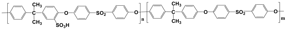
The structural formula of randomly sulfonated polysulfone (SPSFH) is given in Figure 1. The sulfonation was performed on Udel 3500, which is a commercially available extrusion grade produced by Solvay. Polyethersulfone is an amorphous, transparent, rigid polymer, with a Tg = 185 °C (Figure 1).
The molecular weights measured in polystyrene equivalents by size exclusion chromatography (SEC) were Mn = 31,700 and Mw = 51,000 g/mol. The real values, respectively 38,000 and 68,000 g/mol, obtained by SEC-MALLS were slightly higher [13].
It should be emphasized that, probably due to the purification process used by the company, the polydispersity indices were lower than 2. Complementary analysis by MALDI-TOF spectrometry revealed the presence of linear oligomers mainly end-capped by chlorine atoms and OH groups and the presence of cyclic oligomers with molecular weights between 1,366 and 10,076 g mol−1 [13].
By using trimethylsilylchlorosulfonate, a fairly mild reagent, (i) any precipitation in the solvent reaction i.e., dichloroethane can be avoided and (ii) provided the HCl by-product is effectively removed, any chain breaking during the sulfonation can also be avoided. Homogeneous statistical sulfonations retaining the chain lengths of the starting polymer can therefore be obtained. The reaction protocol directly provides either the acid form or the sodium sulfonate form.
Thermal Characterization of the Ionomers
The selected functionality of the ionomers ranged from 0.5 to 0.7 mol H+ (Na+)/repeat monomer unit to ensure a good compromise between conductivity and mechanical properties [14].
The Tg of the sodium sulfonate ionomers were markedly higher than those of their acidic equivalents, themselves higher than that of Udel 3500. The Tg of an ionomer depends on its ionic exchange capacity (IEC) (Table 1). Weight losses started at 260 °C and 340 °C, for SPSFH and SPSFNa respectively, compared with 460 °C for Udel 3500.
2.1. Impact of Extrusion on Macromolecular Backbone
Extrusion of Udel 3500 was performed several times at 340 °C in order to check the stability of the polymeric backbone in the extrusion conditions. No change in the molecular weight distribution of Udel 3500 was detected by capillary viscosimetry or SEC analyses.
2.3. Extrusion of Ionomers
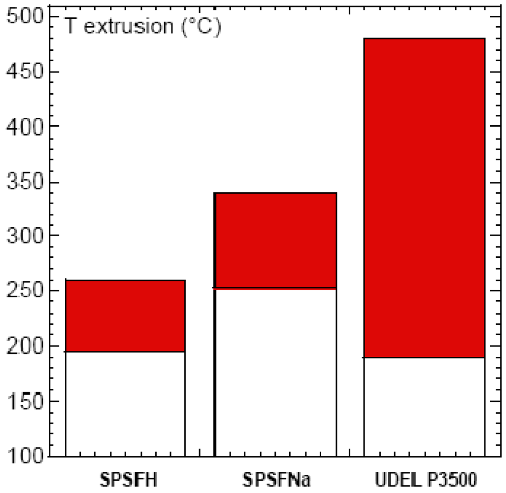
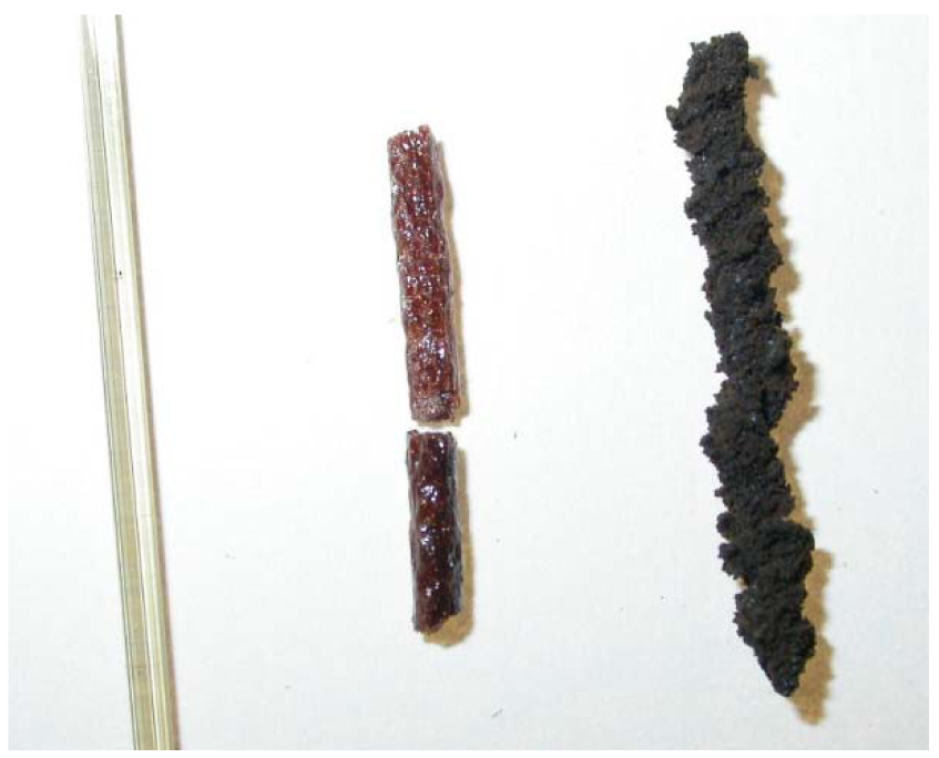
The extrusion temperature range (Text) depends both on the Tg and the Tdeg of the polymers. A semi-empirical criterion, Tg + 100 °C < Text < Tg + 150 °C, can be used to define the extrusion temperature window that will allow a good flow of the polymer to be obtained. In the case of SPSFH, whose IEC and Tg are, respectively, 1.35 H+/Kg and 196 °C, the weight loss started at 260 °C, which means that the extrusion temperature window was very narrow (Figure 2). Even at a moderate temperature, which prevents thermal degradation of the ionomers but is unsuitable for a high-speed process, the flow can lead to local heating causing localized degradation of the ionomer. Preliminary extrusion tests performed on a capillary rheometer, at 210 °C, i.e., Tg + 14 °C and Td − 50 °C, in fact showed good polymer flow but resulted in very rough, brittle extrudates, indicative of degradation (Figure 3).
The temperature window (Tdeg-Tg) i.e., 90 °C for the sodium form SPSFNa is wider than for the acidic SPSFH. The extrusion tests were performed at different temperatures ranging between Tg + 10 and Tg + 70 °C. At temperatures below Tg + 70 °C the polymer did not flow while at Tg + 70 °C extrusion took place but led to a cracked black membrane (Figure 3).
Figure 3 compares the photographs of an extrudate of PSF (Udel 3500) and its ionomeric forms, demonstrating that, even at moderate temperatures, ionomers cannot be extruded into homogeneous non-degraded films.
Since it is possible to obtain extruded films from PSF, the extrusion failure of the ionomers was clearly related to their thermal instability. Even if the weight loss for both ionomeric forms started, according to TGA, at temperatures higher than the selected extrusion temperatures, the extrusion process showed that ionomer degradation (desulfonation, chain breakings, cross-linking) started at a much lower temperature. The discrepancy between TGA data and extrusion tests might be explained by the fact that the process involves both shearing and heating. Care must always be taken when interpreting TGA data, even when the analyses are performed in air. Indeed, weight loss measures the loss of volatile products even though degradations leading to chain breakings and cross-linking can occur without being detected by TGA. Furthermore, in a previous paper, Maréchal et al. reported that model molecules mimicking the ionic monomer of polyethersulfone ionomers underwent weight loss at much lower temperatures than their related ionomers [15]. This was attributed to thermal degradation that led to volatile by-products in the model molecules whereas they led to non-volatile polymer fragments in ionomers. From these results, it is obvious that, whatever the degradation origins, ionomer extrusion cannot be used to produce homogeneous non-degraded membranes. The solution is to perform the extrusion of both ionomer forms in the presence of plasticizers. Our approach involved using water-soluble process-aid plasticizers.
2.4. Extrusion of Ionomers Blended Using Process-Aid Plasticizers
In order to retain the required thermomechanical and electrochemical properties of the extruded membranes the process-aid plasticizers had to be removed after extrusion. These plasticizers were fully removed by immersing the extruded plasticized film in neutral water or in an acidic water solution, in the first case to directly obtain the acidic-form membrane and in the second to acidify the extruded sodium-form membrane. Finally, immersion of the extruded films allows the plasticizers to be replaced by water molecules in the vicinity of the ionic moieties. Because of these constraints, plasticizers must be very carefully selected. Most of the usual plasticizers were found to be inadequate where these objectives were concerned.
2.4.1. Plasticizer Selection
Among the plasticizer selection criteria were their water solubility, their chemical and thermal stability and, obviously, their compatibility with the acidic and alkaline forms of the ionomers.
2.4.1.1. Compatibility
An unusual approach was adopted when selecting process-aid plasticizers compatible with the ionomers. The fairly high ionic species content in the medium—SO3− and M+ (H+ or Na+)—was expected to be decisive in ensuring good compatibility between the ionomers and the plasticizers. Electrolyte design was thus used as the main criterion for selection and was based on the solvating ability of a solvent (i) with respect to cations, through the Donor Number values (DN) which are related to Lewis basicity, and (ii) with respect to anions, through the Acceptor Number values (AN) which are related to Lewis acidity. Ethers and alcohol, due to their oxygen lone pair, have high DN, which favors their interaction with H+ or Na+, while protic groups such as alcohols, due to the polarization of their O–H bond, have, in addition to a high DN, a high AN that should favour their interaction with anions. Therefore water-soluble polar protic plasticizers, such as oligoethers end-capped by OH groups, or polyols, and polar aprotic plasticizers such as sulfolane were selected. In addition, in the case of acidic ionomers, plasticizers of higher basicity than the previous ones, such as sulfonamide and imidazole, were tested. Imidazole would have a dual function (i) neutralization of the acidic functions, which increases the thermal stability of the ionomer [16–19] and (ii) strong interaction with the neutralized acidic functions, which should efficiently plasticize the ionomer.
2.4.1.2. Thermal Stability of Plasticizers
Once the best plasticizers were selected, their stability at the targeted extrusion temperature had to be checked. Indeed, total or partial evaporation of the plasticizers during extrusion would increase the melt viscosity over the course of the process and would be detrimental to the production of homogeneous extruded films.
A 5% weight loss was arbitrarily defined as a critical value for the extrusion of ionomer/plasticizer blends (Table 2).
Two families of plasticizers were investigated. The first are based on polar molecules (Sorbitol, TESA, imidazole), the second on oligomers (DGDME, PEG, Polyol). DGDME appeared to be the most volatile, as it underwent a 5% weight loss from 70 °C and a 30% weight loss at 150 °C. This plasticizer was therefore judged unsuitable. TESA was found to have much better stability and appeared suitable for extrusion temperatures up to 150 °C.
The protic molecular plasticizer, sorbitol, the only one solid at ambient temperature, exhibited outstanding thermal stability, with the critical 5% weight loss occurring at 300 °C. In the second family of plasticizers, evaporation was negligible up to 200 °C, both for polyol and polyethylene glycol, while above 240 °C weight loss became significant.
Since the targeted extrusion temperature was around 150 °C, only DGDME must be excluded on the basis of thermal stability.
2.4.2. Extrusion of Sodium Sulfonated Polysulfone
Rheological measurements and extrusion of sodium sulfonated polysulfone (SPSFNa) were therefore performed with three plasticizers selected on the basis of their ionomer/plasticizer compatibility and thermal stability: sorbitol, PEG and polyol.
2.4.2.1. Influence of Plasticizer
Knowledge of the Tg of the different blends was essential so that the best ones could be formulated and then processed.
Influence of Plasticizer Concentration on Tg—Case of Sorbitol
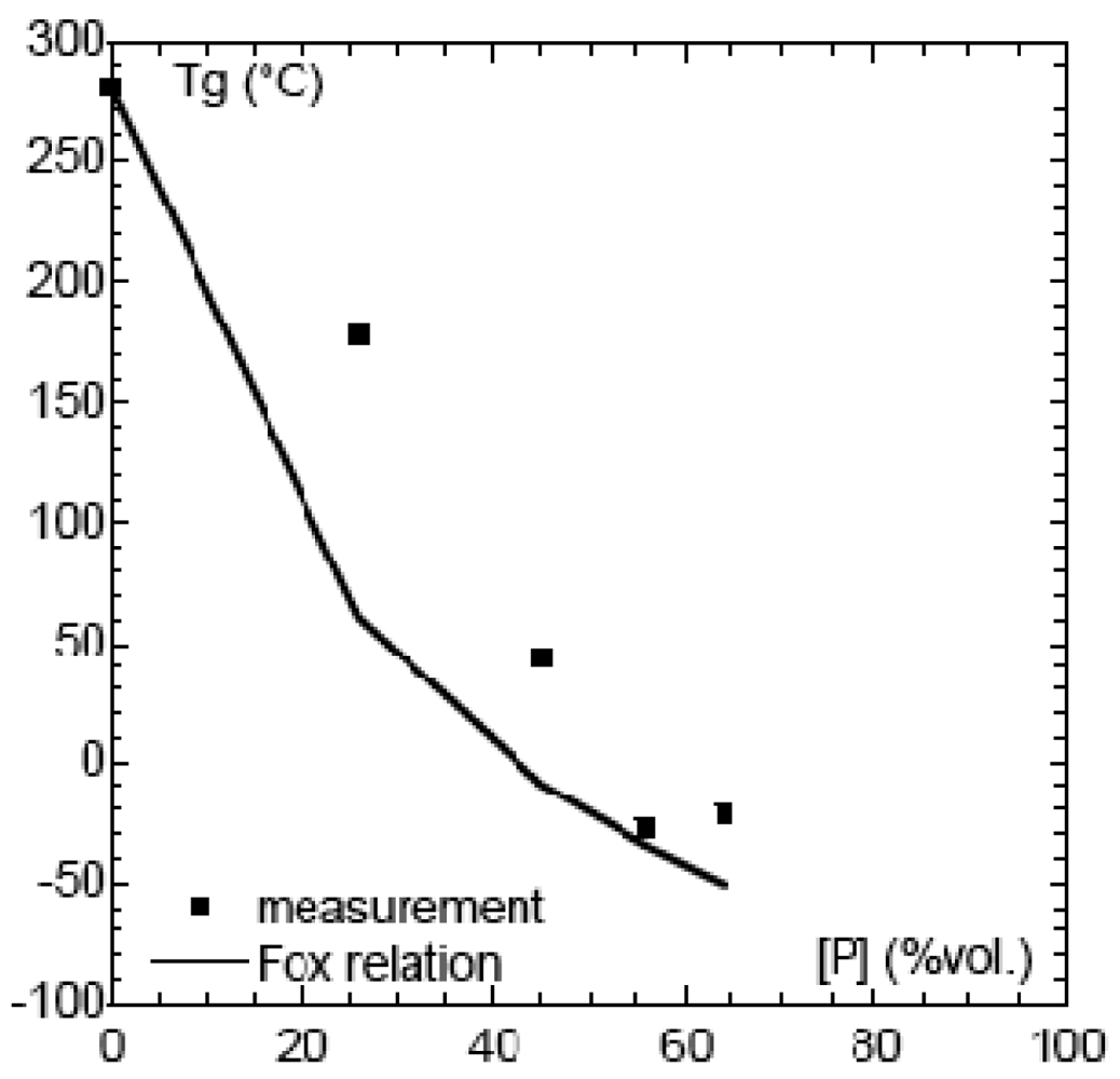
Tg as a function of sorbitol content is represented in Figure 4 and compared with the Tg values calculated from the semi-empirical Flory-Fox relationship.
The Tg of SPSFNa decreased considerably with the addition of sorbitol, dropping from 250 °C for the raw material to 178 °C for the blend containing 26% sorbitol. When the plasticizer content was increased to 56% and 64%, comparable Tg values of −23 °C and −25 °C respectively were obtained. Thereafter, no Tg decrease was observed. For the same plasticizer concentration (40% in volume) the effect was found to decrease according to PEG > polyol > sorbitol.
Influence of Plasticizer Concentration on Flow Properties
The dynamic rheometric characterization was carried out by measuring the elastic and viscous modulus G′ and G″. The flow curves obtained represented the variation in the shear viscosity of the materials over a large range of shear rates. The samples were studied at several temperatures. Using the time-temperature superposition principle, these curves were used to plot a master flow curve covering a broad range of shear rates at a reference temperature. From the master curve and the temperature sensitivity of the blend, it was then possible to deduce the shear rate range within which the sulfonated polyethersulfone could be extruded.
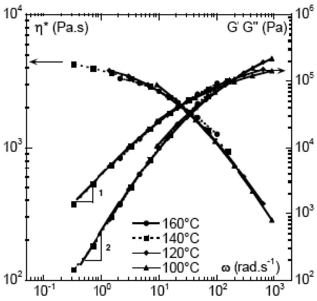
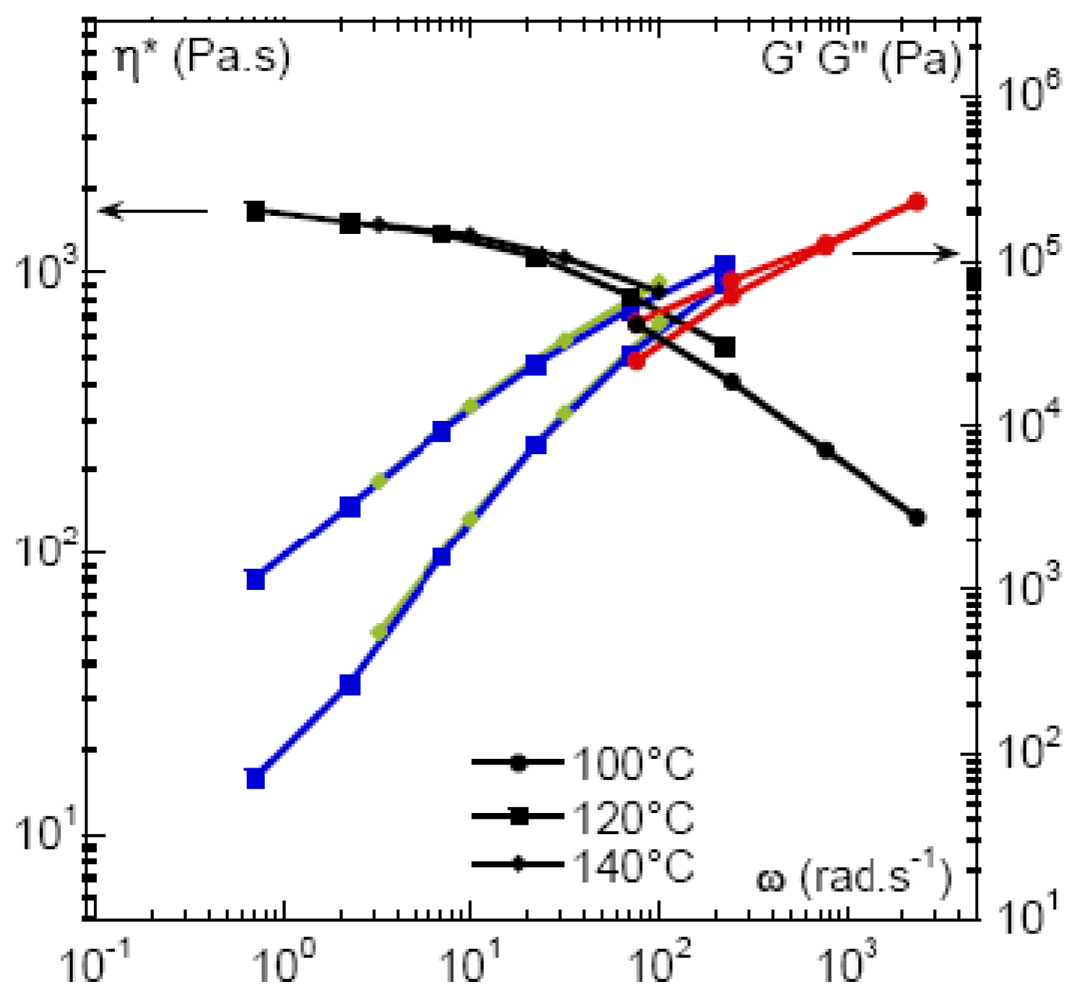
As an example, the behavior of the blend composed of SPSFNa and 40% PEG at the reference temperature of 160 °C is presented in Figure 5.
The curves obtained at different temperatures superpose well and the time-temperature superposition principle works reasonably well. The rheometric curves obtained at 100, 120, 140 and 160 °C were superposed over 4 frequency decades. The material behaved like a classic melted polymer, with a Newtonian plateau towards 4,000 Pa s and shear-thinning behavior starting from frequencies higher than 10 rad s−1. The time-temperature superposition principle can be used to evaluate the behavior of materials up to frequencies of 1,000 rad s−1, thus covering the range of shear rates used in industrial extrusion.
The others blends studied presented similar flow behavior.
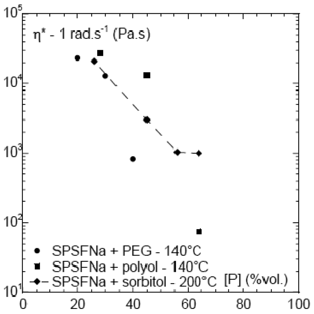
In order to compare the effect of the three plasticizers considered, the complex viscosity measured at 1 rad s−1 for all the blends is shown according to plasticizer volume in Figure 6.
At 25% plasticizer content, similar viscosities were obtained for PEG, polyol, and sorbitol at respectively 140, 140 and 200 °C. Thus, the decrease in viscosity was more significant with PEG and polyol than with sorbitol.
2.4.3. Extrusion of Sulfonated Polysulfone in Acidic Form
The plasticizers used for sodium sulfonated polysulfone were also tested as process-aid plasticizers for extrusion of the acidic ionomer. However, both sorbitol and polyol were found to be unstable in the presence of this ionomer. The blends of polyol or sorbitol and sulfonated polymer (40/60% volume) flowed at about 150 °C but after 2 min became black and their viscosity increased. This behaviour can be explained by the acid-catalyzed dehydration of the alcohol functions of the plasticizers induced by the aryl sulfonic moieties of the ionomer (Scheme 1). The possibility of performing SPSFH extrusion without degrading the ionomers was investigated with PEG and two other plasticizers that are more stable in the presence of acids, namely imidazole and TESA.
2.4.3.1. Influence of Plasticizer on Glass Transition Temperature
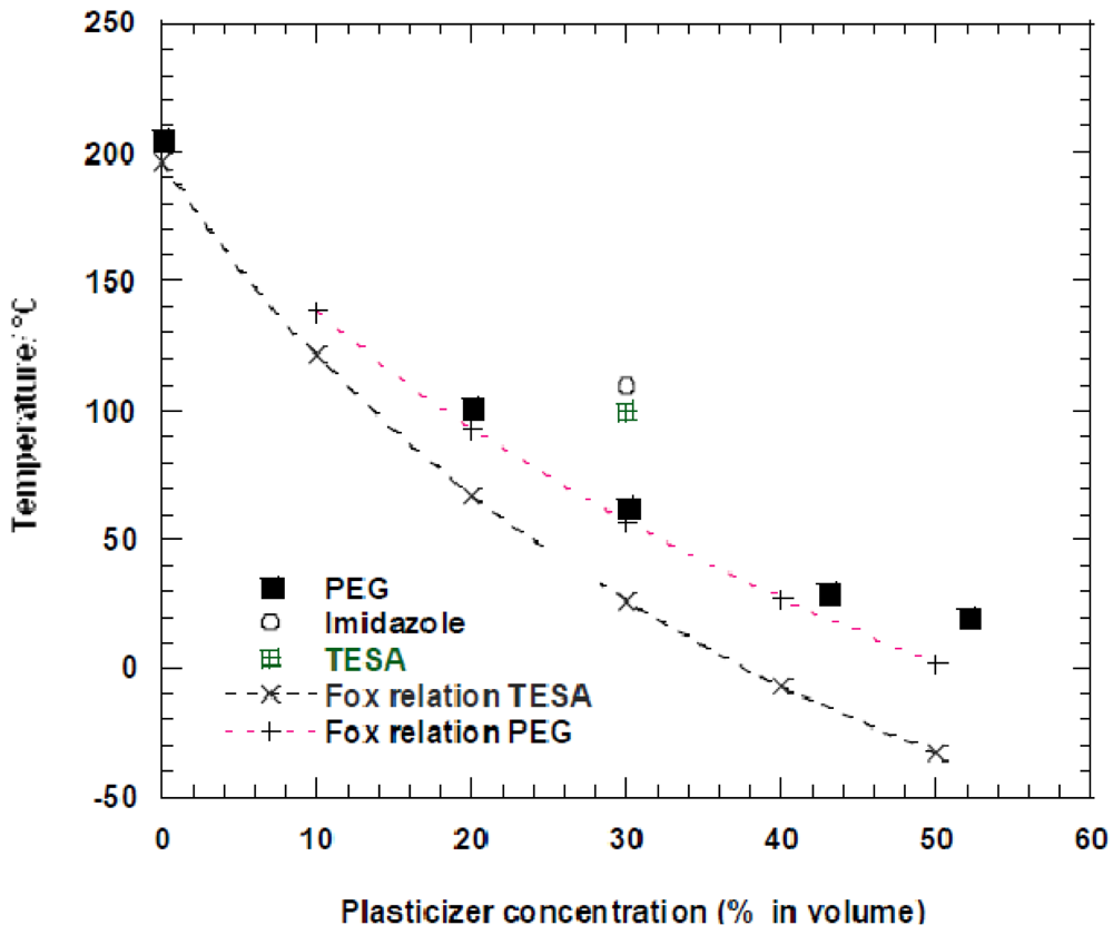
The evolution of the glass transition temperature as a function of PEG volume was compared with the values obtained at just one concentration, i.e., 30, using TESA and imidazole (Figure 7).
As in the case of the plasticization of SPSFNa, PEG was shown to be the most efficient plasticizer of SPSFH. In a wide concentration range, the measured Tg of the SFSFH+PEG blends were found very close to those calculated using the Flory-Fox relationship. On the contrary, the measured Tg of SPSFH blended with 30% of TESA was approximately 70 °C higher than the calculated one. In the case of imidazole, the Tg of the blend was slightly higher than that obtained with TESA. From these data, it might be inferred that, in addition to its affinity with the ionic moieties, PEG has a fairly good affinity with the polymer chain while TESA and imidazole interact mainly with the ionic functions.
Comparison of the Effect of the Three Plasticizers on the Viscosity
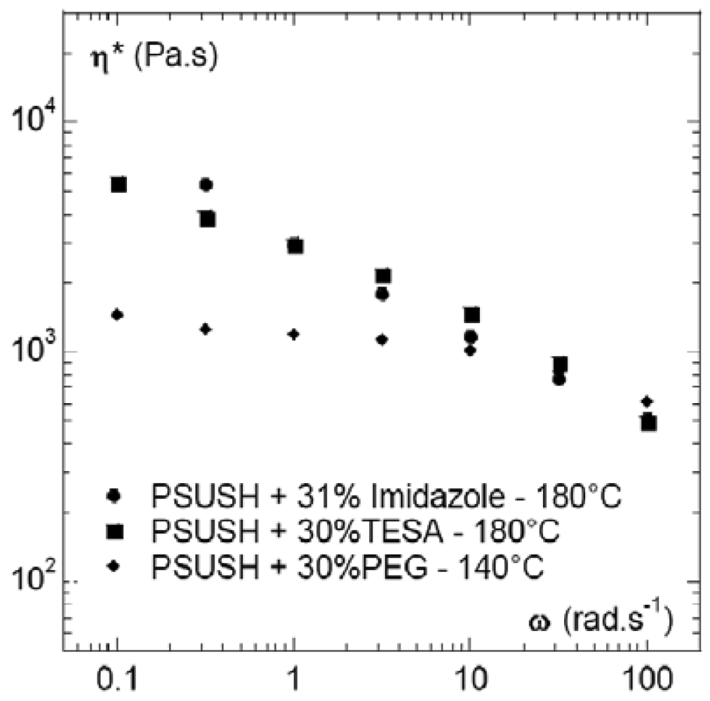
Figure 8 compares the effect of the three plasticizers, at 30% volume content, on the viscosity of the SPSFH blends. The viscosity values, at low frequency (0.1 rad s−1) and 180 °C, were very close for the SPSFH plasticized by imidazole and tetrasulfonamide while, even at a much lower temperature, i.e., 140 °C, the viscosity of SPSFH plasticized by PEG was five times lower. However, at frequencies exceeding 10 rad s−1, the three blends became very fluid and more or less converged towards the same viscosity values. On the basis of the viscosity data, all of the plasticizers could therefore be used to process SPSFH by extrusion.
Despite the possible sensitivity of its ether functions to acids, PEG allowed the polymer melts to flow at 140 °C. However, at 180 °C and in the presence of SPSFH acidic functions, the use of PEG was questionable. On the other hand, TESA and imidazole seemed sufficiently stable to perform SPSFH extrusion up to at least 180 °C. This higher chemical/thermal stability is indisputably an asset in terms of the prospect of scaling-up the laboratory protocol since, for instance, it will enable the process-aid plasticizer content to be lowered without damaging the extruded membrane. However, in the present paper, emphasis will be placed on PEG blends.
Behaviour of SFSFH/PEG Blends
Using 120 °C as a reference temperature, the behaviour of the blend, containing 30% volume PEG, was investigated with respect to temperature (Figure 9).
TTS allowed the variation in viscosity to be represented over almost four decades of shear rates. The behavior was that of a shear thinning fluid, with a viscosity plateau around 2,000 Pa s and a decrease in viscosity occurring at about 10 s−1.
The characterization of the sample is not accessible at the lowest frequencies, because the measurements last sufficiently to lead to a partial evaporation of PEG. This is in particular reflected by the elastic modulus, which seems to increase at low shears. This artifact that might be related to PEG degradation, leading to low molecular weight fragments, is more easily observed at low frequencies. These results underline once again that, due to the chemical sensitivity of PEG to acids, the mechanical and thermal stability of its blends with SPSFH is difficult to control.
2.5. Extrusion of Composite Ionomers
It has been found that proton-conducting inorganic fillers can be advantageously added to ionomers in order to improve membrane conductivity, while limiting its swelling, and allowing the operating temperature of the fuel cells to be increased [3–6]. In addition, a more classic approach involving composites based on fibers can also be used to reinforce the mechanical strength of the membrane and so delay the loss of mechanical properties induced by chemical/electrochemical degradation occurring during fuel cell operation. Here, we report some preliminary results on the assessment of the extrusion of composite ionomers.
2.5.1. Extrusion of Composites Based on Phosphatoantimonic Acid
H3, H3Sb3O6(PO4)2x(H2O), is a hydrophilic strong inorganic acid that undergoes a reversible dehydration process between room temperature and 320 °C where the anhydrous form H3Sb3O6(PO4)2 is obtained. Previous reports [3] showed that, due on the one hand to its water uptake and on the other to its high conductivity in the presence of water; H3 allows ionomers of moderate IEC to be used. It was found that despite the moderate IEC, the synergy between H3 and the ionomers led to conductivities very close to those reached at high IEC while avoiding mechanical weakening of the membrane. In addition to its electrochemical contribution, H3 has been found to reinforce sulfonated polysulfones as compared with unfilled ones. The addition of H3 fillers to the ionomer solution creates problems in the film casting process because of the high density of the fillers, and even at the laboratory scale this often leads to heterogeneous distribution of the filler in the membrane. Extrusion of composite ionomers should lead to more homogeneous distributions of the fillers in the extruded membrane. However, H3 being a strong inorganic acid, when used in combination with high shear rates and high temperatures it might induce polymer chain breakings. To make sure that the polymeric skeleton did not suffer degradation we first checked its stability in the presence of H3 at high temperatures. Indeed, SEC showed that the molecular weight distribution of PSF was unaffected by extrusion at 260 °C of extrusion grade PSF, i.e., Udel 3500™, blended with H3 [7]. The feasibility of H3 composite extrusion was therefore assessed both for the acidic and the sodium forms of the ionomer.
2.5.1.1. Extrusion of Ternary Blend SPSFNa/H3/Plasticizer
On the basis of the above findings, extrusion of SPSFNa would seem a priori easier, due to the chemical compatibility of the ionomer with several plasticizers. The presence of H3 in the blends might, however, restrict the choice of plasticizers. Table 3 summarizes the experimental data obtained with 3 plasticizers.
This table shows that H3 behaved like SPSFH, leading to degradation of plasticizers with a high content in alcohol functions such as sorbitol and polyol. This probably originated from their acid-catalyzed dehydration, with the formation of alkenes that underwent further degradation. Although end-capped by an OH function, PEG appeared as an efficient plasticizer for the composite. This is related (i) to its low concentration in OH functions and (ii) to the moderate operating temperature of 140 °C that can be used thanks to the very efficient plasticization afforded by PEG. The following SEM picture (Figure 10) shows that H3 was fairly well dispersed in the composite. Although it was shown that these composites could be easily extruded, a cation exchange remains possible between the sodium cations of the ionomer and the acidic groups of H3 that could partly turn H3 into Na3. The exchange rate is probably markedly slower in a melt than in a solution, but cannot be completely avoided. While it is easy to turn a membrane consisting of SPSFNa into SPSFH, turning Na3 into H3 requires very harsh acidic treatment that would degrade the polyethersulfone backbone. Therefore we decided to investigate the extrusion of ternary blends based on the acidic ionomers.
2.5.1.2. Extrusion of Ternary Blend SPSFH/H3/Plasticizer
Although acidic sulfonated polysulfone SPSFH was successfully plasticized by PEG, imidazole and TESA, we selected the latter as a process-aid plasticizer for this composite blend. Indeed, first of all we were more confident about its stability as compared with PEG versus a blend combining two strong acids, namely arylsulfonic and phosphatoantimonic acids, and, second, we feared a partial neutralization of H3 by imidazole that might be difficult to reverse. A blend comprising SPSFH/10%H3/30TESA in volume was prepared in a Rheomix at 100 °C and 80 tr min−1. This process was found to be slightly exothermic, the temperature reaching 120 °C, and led to a homogeneous blend. This blend was characterized through its shear behavior and compared at 160 °C with SPSFH/30TESA.
To be valid, rheometric measurements on composite polymers require an absence of sedimentation of the fillers during the measurement time. Indeed, even if the initial blend appears homogeneous, any sedimentation of the filler occurring during the measurements would change the blend characteristics. However, the very high viscosities of our material led to very low Stokes numbers, associated with sedimentation rates as low as 10−10 m s−1. The question of sedimentation could therefore be disregarded.
Dynamic rheometry measurements performed at 160 °C provided characterizations of the samples over three decades of shear rates (between 10−2–102 s−1) (Figure 11). Shear rheometry performed on both filled and unfilled plasticized ionomers revealed their similar behavior. The composites followed Einstein's law, relevant for polymers blended with spherical particles. A roughly 30% increase in the viscosity of the filled blends was observed. These data confirmed that such blends could be extruded at 160 °C.
2.5.2. Extrusion of Ternary Blend SPSFNa/Fibres/Process Aid-Plasticizers
The selected composite was composed of SPSFNa plasticized by 40% PEG (in volume) and 15% alumina fibers (in volume). The fibers were between 100 and 200 nm in length. The following Figure 12 shows a homogeneous dispersion of alumina whose shape is quasi-spherical with a diameter close to 20 microns. It is clear that the alumina fibers tended to aggregate during the blend preparation and this was probably due to electrostatic forces.
Figure 13 shows the viscosity curve for the composite plasticized sample obtained using TTS at a reference temperature of 140 °C, together with the variations of the elastic and viscous modules. The viscosity of the unfilled material is also shown.
At the lowest frequencies, reinforcement was highlighted—in agreement with Einstein's law on spherical particles—by an increase in viscosity of approximately 30%: 5 × 10³ Pa s and 4 × 10³ Pa s respectively for the filled and unfilled blends (10−1 rad s−1,140 °C). On the other hand, at higher frequencies the reinforcement was significantly higher, with viscosity tripled (6 × 10² Pa s at 103 rad s−1). The evolution of reinforcement with the shear frequency might be explained by a change in the shape of the fillers. Indeed, it was observed that aggregation of the alumina fibers occurred during the blend preparation. These aggregates were probably separated during shearing measurement, thus leading to a sample with a higher effective concentration of fillers with a smaller diameter. According to Einstein's law, such a sample is obviously characterized by increasingly higher viscosity. These data confirm the feasibility of extruding ionomer composites containing reinforcing fibers. In addition, the possibility of extruding ionomer composites based on other fibers such as silica, carbon and Kevlar was also demonstrated. Because of their electronic conductivity, the composites based on carbon fibers are obviously unsuitable for use in fuel cell membranes. All of the composites were successfully extruded using a capillary rheometer equipped with an exit slit die measuring 0.8 mm × 10 mm × 5 mm. The extrusion process produced highly flexible films.
2.6. Elimination of Process-AidPlasticizers
One of the main criteria used for the selection of process-aid plasticizers was their water solubility. Indeed, their retention by the membrane would be detrimental both to its mechanical properties and to its electrochemical stability. The extruded films were therefore immersed at ambient temperature for 24 to 48 h in permuted water in order to remove the plasticizer. This protocol can be used for all the extruded films (acidic or alkaline form, filled or unfilled). For the SPSFNa extruded films, immersion in an acidic solution instead of neutral water is an attractive solution since, at the same time, the sodium cation is replaced by the proton. NMR analyses confirmed the total removal of the plasticizer. As an example, Figure 14 compares the 1H NMR spectra of sorbitol and of SPSFNa extruded with sorbitol and then immersed for 24 h in permuted water. The spectra demonstrate unambiguously that all the plasticizer was removed.
2.7. About Membrane Porosity
Following the elimination of the process-aid plasticizers, one can fear the formation of macropores in the extruded membrane. At the macroscopic level, the removal of the process-aid plasticizer did not result in white membranes but in perfectly transparent ones. Now, phase inversion process usually generates white macroporous membranes. Comparative preliminary MEA tests, performed on membranes obtained by film casting and extrusion did not allow detecting porosity detrimental to the membrane performances (cross-over). Generation of macropores is however a drawback that must be considered, when moving from semi-pilot scale to large scale production. How to overcome this possible drawback in a R&D optimization of the extrusion process?
First, while a large content of plasticizer was used in order to provide the deliverable, i.e., extrusion of a 5 kg of ionomer, the process optimization should allow the plasticizer content to be decreased down to 20% or less. Second, a post-calendaring of the extruded blends, prior to the plasticizer removal by immersion of the film in water, has been considered.
Indeed, additives, such as process-aid plasticizers, are short molecules as compared to ionomer chains. It is well-known that during the processing of formulated polymers, the short molecules move towards regions of high shear. Thus, from the surface analysis of the extrudate, it has been shown that the extrusion of the plasticized ionomers results in a concentration of the process-aid plasticizers on the die walls, creating thus a thin lubricating film which allows improving the performance of extrusion. It may be therefore suggested that the same phenomenon should occur with the help of a post-calendaring of the extruded blend, allowing the plasticizer moving towards the region of high shear, namely the surface of the membrane. This will allow decreasing the plasticizer content in the extruded film. This post-calendaring combined with a decrease in the content of process-aid plasticizer, should make easier the plasticizer removal while avoiding the formation of a macroporosity.
2.8. Impact of Extrusion on Electrochemical Performance
This paper does not claim to have invented a membrane providing the best current density and lifespan of the related MEAs, but to have demonstrated the feasibility of processing fuel cell membranes by extrusion. A crucial aspect was, however, to assess the impact of extrusion on the electrochemical performance of a given membrane, as reflected both by the redox stability of the membrane and by its contribution to the internal resistance of the MEA.
In terms of redox stability, a decrease in the electrochemical stability of the membrane resulting from the extrusion might have been expected: local degradation, by-products insoluble in water, etc. In fact, the cyclic voltammetry analysis comparing solutions of pristine ionomers and of extruded ionomers did not reveal any degradation following extrusion [7].
As for the membrane's contribution to the MEA's internal resistance, this depends on its proton conductivity and on its thickness. It was verified that proton conductivity, even for the reinforced membranes, was unaffected by extrusion. On the other hand, the thinner the membrane, for a given conductivity, the lower the ohmic drop was found to be. Decreasing the membrane thickness is conditional on it having good mechanical performance, which itself is dependent on the molecular weight distribution of the ionomers. Thus, chain breakings lead to brittle membranes [13]. It was confirmed that the extrusion of plasticized ionomers did not result in any change in molecular weight distribution. A comparative folding test was performed on the membranes processed by film casting and by extrusion. For that purpose the membranes were immersed in water maintained at 70 °C. The lifespan of the membranes obtained by film casting reached 6,000 h while that of the extruded membrane reached 7,000 h. In addition, whatever the reinforcement level induced by the composites, the composite membranes should at least retain the mechanical performance of unfilled membranes.
3. Experimental Section
3.1. Materials
Trimethylsilyl chlorosulfonate (TMSClS) was purchased from Aldrich, used as received and stored in a glove-box under dry argon. Polysulfones (PSF), commercialized by Solvay as Udel 3500, are amorphous, transparent and rigid polymers. For our experiments we used different plasticizers: polyethylene glycol (PEG) with an average molecular weight of 400 g/mol purchased from Fluka, polyol CARADOL ET570 from Shell, DGDME (diethylene glycol dimethylether), sorbitol, imidazole and tetraethylsulfonamide (TESA) were purchased from ACROS. The characteristics of the plasticizers used are presented in Table 2.
3.2. Sulfonated Polysulfone Preparation
Polyethersulfone was sulfonated in 1,2-dichlorethane by addition of trimethylsilylchlorosulfonate. The reaction was performed in anhydrous conditions under an Argon flow, which allowed the gaseous HCl, generated by the electrophilic substitution, to be removed promptly. Trimethylsilylchlorosulfonate (TMSClS) was chosen as the sulfonating reagent because it is among the less aggressive reagents [3,13,14,20]. Moreover, due to the formation of a trimethylsilyl sulfonic ester rather than a sulfonic acid, the hydrophobic character of PSF was retained and prevented any partial precipitation during the reaction. As a result, a homogeneous sulfonation was obtained.
The reaction mixture was then stirred for 17 h at 40 °C. By precipitation of sulfonated polysulfone, the sulfonated function was obtained in acid form (SPSFH), when the polymer solution was poured into diethylether, and in sodium sulfonated form (SPSFNa), when the polymer was poured into a 1 M solution of sodium ethoxide in ethanol [13]. After filtration the polymer was successively washed with ethanol and water and dried under vacuum at 65 °C for 48 h.
3.3. Thermogravimetric Measurements
Thermogravimetric measurements were carried out with a Netzsch STA409 thermal analyzer.
The sample was heated at a rate of 5 °C/min. By convention, we considered the temperature when the weight loss was equal to 5% of the initial mass as the beginning of the degradation of the polymer backbone for the sulfonated polymer, and as the critical evaporation temperature for the analysis of the plasticizer. Plasticizers presenting a weight loss higher than 5% at the extrusion temperature were discarded as they could not be used to process the sulfonated polyethersulfone.
3.4. Glass Transition Temperature Measurements
Glass transition temperatures were determined by Differential Scanning Calorimetry (DSC).
Tg was measured in nitrogen flow using a TA Instruments DSC 2920 modulated DSC. In a typical procedure, samples were cooled rapidly from room temperature to −100 °C. Then the samples were heated at 5 °C/min (10 °C/min with non-modulated mode) to 300 °C. The oscillation period was 60 s and its amplitude was 1 °C. Tg were taken at the inflection point of the specific heat increment of the glass-rubber transition and determined within an accuracy of ±1 °C.
3.5. Preparation of Blends
The blends of sulfonated polyethersulfone and the plasticizer at different concentrations were prepared in a Haake Rheomix batch mixer with two counter rotating rotors and a 70 cm3 mixing chamber. Depending on the components for each blend, processing temperatures ranged from 60 to 200 °C. The rotor speed was set to 50 tr min−1, which corresponds to an average shear rate of 50 s−1 [21].
First, the polymer and the plasticizer were mixed together in a glass vessel before being poured into the mixer hopper. After 20 min of mixing, as a compromise between homogeneity of blend and thermal dissipation, the molten blend was extracted. It appeared as a high-viscosity brown paste that was homogeneous at length scales observable by optical microscopy.
After cooling and solidification at ambient temperature, the blend was crushed by an IKA blade crusher equipped with a sieving grid that gave an average particle size smaller than 2 mm. Particles of this size could then be used to prepare samples according to the needs of each of the different characterization techniques used.
Table 4 summarizes the composition and mixing temperature of all the blends studied.
3.6. Preparation of Membranes
From the powder obtained from the above mixtures, membranes were prepared using a Gottfert Rheotester 1500 capillary rheometer with a slit die 5 mm in length and a cross section of 16 × 0.8 mm2 at the exit. The capillary rheometer is equipped with a piston that pushes a fixed volume of fluid through a small orifice die at a controlled temperature and controlled speed.
The extrusion temperature depends on the glass transition temperature of the blend. By keeping the shear rate low enough, any extrusion defects due to stress concentration near the singularity at the die exit were avoided. The membranes were stretched at the die exit to obtain the desired thickness of 0.2 mm.
3.7. Rheometric Measurements
The rheometric measurements were performed using an ARES rotational rheometer from Rheometric Scientifics. The parallel plate geometry, with a 25 mm diameter plate and a gap between the plates of 1 mm, was used. This geometry was chosen to facilitate the positioning of the sample on the rheometer as explained below. All the rheological tests were based on dynamic measurements using small amplitude oscillatory shear deformations [22]. The elastic and viscous modulus, G′ and G″, as a function of the frequency of the oscillations ω were measured. The complex viscosity η*(ω) was deduced from these measurements. In many cases, this complex viscosity is found to be a good evaluation of the shear viscosity. η(γ̇). Moreover, for viscoelastic material, the empirical Cox Merz rule [22] is found to work very well. It enables η* and η to be linked according to the following relation:
The shear rate being expressed in s−1 and the frequency in rad s−1.
The aim of the rheometric study was to determine the optimal temperature and shear conditions for processing the blends. The following experimental protocol was used:
First, for a given temperature, the linear viscoelastic regime was determined by carrying out a strain sweep at a fixed frequency. The strain range varied from 0.1% to 100%. The frequencies used were fixed at 1, 10 and 100 Hz.
Next, isothermal frequency sweeps were carried out at different temperatures within the linear viscoelastic regime and the elastic and viscous modulus measured. These frequency sweeps were performed in the range 100 and 0.01 rad s−1 starting with the highest frequencies. In this way, less time was needed to obtain a greater number of data points and thermal degradation of the fluid was minimized. Moreover, in order to improve the precision of the measurements, the total frequency range was divided into two independent sweeps: the first sweep for the frequencies between 100 and 1 rad s−1 with a strain of 1%, and the second sweep for frequencies ranging from 10 to 0.01 rad s−1 with a strain of 10%. Since measurements were made on two overlapping intervals, their reproducibility was checked.
An air-heated oven was used to keep the sample at the desired temperature during the experimental runs. In addition, some experiments were carried out under a nitrogen flow to slow down possible thermal degradation of the sample.
Since the samples could not be installed easily on the rheometer because of their solid state at ambient temperature, they were prepared by initially compressing the blend and then melting it in a mould with a disk-shaped cavity 25 mm in diameter and 1 mm thick. To do this, the mould was filled with the powder blend and closed as tight as possible at ambient temperature. The mould was then placed in an oven for approximately one hour, which is the time necessary for the blend to melt and flow within the mould cavity. Next, the mould was closed again to compress the fluid. The mould was withdrawn from the oven and placed at room temperature for cooling. Disk-shaped samples were obtained and used for dynamic rheometric experiments.
The Time-Temperature Superposition principle expresses both time and temperature as a single variable to describe the viscoelastic properties of materials [23]. Frequency sweeps at various constant temperatures are superposed using an empirical horizontal shift factor (aT) to form a single master curve at a reference temperature Tref. In addition, a vertical shift factor bT equal to Tref/T is applied. Changes in density due to the temperature change are ignored. The TTS allows the shear behavior of the sample to be represented over a broader range of shear rates as compared with is the results obtained when considering only one temperature.
3.8. NMR Analysis
10 mg of extruded membrane was dissolved in DMSO D6 (calibration: δ = 2.49 ppm). A Brucker cryospec WM 250 spectrometer-frequency 250 MHz at 22 °C was used. The NMR analysis was performed to check that the plasticizer had been removed from the membrane by washing with water.
4. Conclusions
We have demonstrated that polyethersulfone ionomers, which are promising materials for membrane fuel cells, can be processed by extrusion, with the addition of plasticizer. Since the usual plasticizers were unsuitable for extrusion, water-soluble process-aid plasticizers exhibiting high interaction with the ionic moieties were selected. When the extruded membranes were immersed in water the plasticizer was totally removed, with the plasticizers replaced by water molecules in the vicinity of the ionic groups. Filled and unfilled ionomers were successfully extruded into membranes without impacting on mechanical or electrochemical performance. Extrusion feasibility was also demonstrated on a variety of ionomers based on a variety of high-performance polymer backbones including poly-ether-ether-ketone, polyimide, polybenzoxazole [8–10]. We believe that the extrusion process, the easy removal of the process-aid plasticizer by water and the extension of the approach to a variety of ionomers are an important contribution to the Life Cycle Assessment of fuel cell membranes and pave the way for future improved membranes.


| Product | IEC (M+ kg−1) | Glass transition temperature (°C) | Degradation temperature (°C) |
|---|---|---|---|
| SPSFH | 1.35 | 196 | 260 |
| SPSFH | 1.6 | 210 | 256 |
| SPSFNa | 1.30 | 250 | 340 |
| SPSFNa | 1.18 | 240 | 343 |
| PSF | 0 | 185 | 460 |
| Product name | Chemical structure | Density (20 °C) | Molecular weight (g mol−1) | Tg (°C) | Tm (°C) | 5% weight loss (°C)** |
|---|---|---|---|---|---|---|
| Sorbitol | 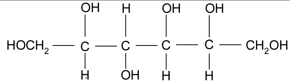 | 1.49 | 182 | <−100 | 110* | 295 |
| Polyol ET570 |  | 1.075 | 300 | −60* | 220 | |
| PEG (Polyethylene glycol) |  | 1.13 | 400 | −78* | −3* | 220 |
| DGDME (Diethylene glycol dimethyl ether) |  | 0.937 | 134 | <−100 | −64 | 162 |
| Imidazole | 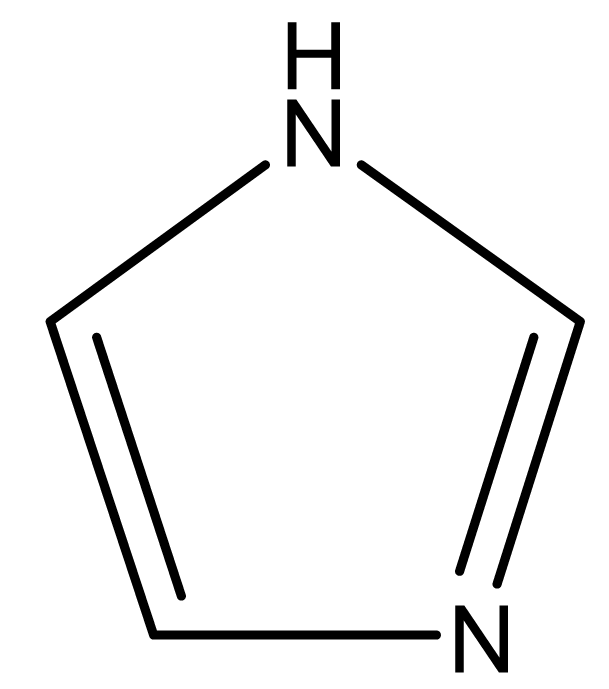 | 68 | - | 88 | 256 | |
| Tetraethy lsulfamide(TESA) |  | 1.03 | 208.3 | −111 | −48 | 250 |
*measured by modulated differential scanning calorimetry, under nitrogen flow, 5 °C/min. Others characteristics are from product manufacturers.**measured by thermogravimetric analysis (TGA).
| Plasticizer(%volume) | H3 content (%volume) | Temperature(°C) | Remarks | Blend aspect |
|---|---|---|---|---|
| 40% PEG | 10% | 140 | Bright yellowish homogeneous | |
| 10% sorbitol | 10% | 190 | Degradation, unpleasant smell | black brittle |
| 5% polyol | 10% | 160 | Degradation, unpleasant smell | black |
| Polymer | Charge | Plasticizer name | Plasticizer concentration in volume (%) | Charge concentration in volume (%) | Preparation temperature(°C) |
|---|---|---|---|---|---|
| SPSFNa (IEC = 1.3 Na+/kg) | – | Sorbitol | 26 | – | 200 |
| 45 | 190 | ||||
| 56 | 180 | ||||
| 64 | 180 | ||||
| SPSFNa (IEC = 1.3 Na+/kg) | – | Polyol | 28 | – | 180 |
| 45 | 170 | ||||
| 64 | 100 | ||||
| SPSFNa (IEC = 1.3 Na+/kg) | – | PEG | 20 | – | 180 |
| 30 | 100 | ||||
| 40 | 100 | ||||
| SPSFH (IEC = 1.35 H+/kg) | – | PEG | 20 | – | 140 |
| 32 | 140 | ||||
| 43 | 120 | ||||
| 52 | 90 | ||||
| SPSFH (IEC = 1.35 H+/kg) | – | Imidazole | 32 | – | 160 |
| SPSFH (IEC = 1.35 H+/kg) | – | TESA | 30 | – | 160 |
| SPSFH (IEC = 1.35 H+/kg) | H3 | TESA | 30 | 10 | 120 |
| SPSFNa (IEC = 1.3 Na+/kg) | Alumina fibres | PEG | 40 | 15 | 120 |
Acknowledgments
This work was funded by the Rhône-Alpes Regional Council and was carried out as part of the ECOPAC project under the “Energies” research programme. For the study, we collaborated with two industrial partners, ERAS-LABO and BATSCAP.
References
- Iojoiu, C.; Chabert, F.; Maréchal, M.; El Kissi, N.; Guindet, J.; Sanchez, J.-Y. From polymer chemistry to membrane elaboration: A global approach of fuel cell polymeric electrolytes. J. Power Sources 2006, 153, 198–209. [Google Scholar]
- Curtin, D.E.; Lousenberg, R.D.; Henry, T.J.; Tangeman, P.C.; Tisa, M.E. Advanced materials for improved PEMFC performance and life. J. Power Sources 2004, 131, 41–48. [Google Scholar]
- Genova-Dimitrova, P.; Baradie, B.; Foscallo, D.; Poinsignon, C.; Sanchez, J.-Y. Ionomeric membranes for proton exchange fuel cell (PEMFC): Sulfonated polyethersulfone associated with phosphatoantimonic acid. J. Membr. Sci. 2001, 185, 59–71. [Google Scholar]
- Alberti, G.; Casciola, M. Composite membranes for medium-temperature PEM fuel cells. Ann. Rev. Mater. Res. 2003, 33, 129–154. [Google Scholar]
- Jones, D.J.; Rozière, J. Handbook of Fuel Cells—Fundamental, Technology and Applications; Vielstick, W., Gasteiger, H., Lamm, A., Eds.; Wiley & Sons: New York, NY, USA, 2004. [Google Scholar]
- Baradie, B.; Poinsignon, C.; Sanchez, J.-Y.; Piffard, Y.; Vitter, G.; Bestaoui, N.; Foscallo, D.; Denoyelle, A.; Delabouglise, D.; Vaujany, M. Thermostable ionomeric filled membrane for H2/O2 fuel cell. J. Power Sources 1998, 74, 8–16. [Google Scholar]
- Sanchez, J.-Y.; Chabert, F.; Iojoiu, C.; Salomon, J.; El Kissi, N.; Piffard, Y.; Marechal, M.; Galiano, H.; Mercier, R. Extrusion: An environmentally friendly process for PEMFC membrane elaboration. Electrochim. Acta 2007, 53, 1584–1595. [Google Scholar]
- Sanchez, J.-Y.; Iojoiu, C.; Drevet, H.; El Kissi, N.; Rey, I.; Chabert, F.; Galiano, H. Preparation of Films Comprising a Polymer Having Anionic Groups. FR2893624, May 2007.
- Sanchez, J.-Y.; Iojoiu, C.; Piffard, Y.; El Kissi, N.; Chabert, F. Manufacture of Membranes by Extrusion of a Thermoplastic Polymer Bearing Acid Groups. FR2883292, 22 September 2006; EP1858631, 28 November 2007.
- Sanchez, J.-Y.; Iojoiu, C.; Mercier, R.; Marechal, M.; El Kissi, N.; Galiano, H.; Chabert, F. Preparation of Films Comprising a Polymer Having Anionic Groups FR2883293, 22 September 2006; EP1853644, 14 November 2007.
- Chabert, F. Elaboration de membranes polymères pour piles à combustible par extrusion. Ph.D. Thesis, Institut National Polytechnique de Grenoble, Grenoble, France, 2004. [Google Scholar]
- Cerfontain, H.; Schnitger, B.W. Recueil des Travaux Chimiques des Pays-Bas; Elsevier: Maryland Heights, MO, USA, 1972; Volume 91, p. 199. [Google Scholar]
- Iojoiu, C.; Genova-Dimitrova, P.; Marechal, M.Y.; Sanchez, J.-Y. Chemical and physicochemical characterizations of ionomers. Electrochim. Acta 2006, 51, 4789–4801. [Google Scholar]
- Baradie, B. Membranes ionomères composites pour piles à combustible H2/O2. Elaboration et caractérisation. Ph.D. Thesis, Institut National Polytechnique de Grenoble, Grenoble, France, 1997. [Google Scholar]
- Maréchal, M.; Wessel, R.; Diard, J.-P.; Guindet, J.; Sanchez, J.-Y. Study of pemfc ionomers through model molecules mimicking the ionomer repeat units. Electrochim. Acta 2007, 52, 7953–7963. [Google Scholar]
- Iojoiu, C.; Hana, M.; Molmeret, Y.; Martinez, M.; Cointeaux, L.; El Kissi, N.; Teles, J.; Leprêtre, J.-C.; Judeinstein, P.; Sanchez, J.-Y. Ionic Liquids and their hosting by polymers for HT-PEMFC membranes. Fuel Cell 2010, 10, 778–789. [Google Scholar]
- Di Noto, V.; Negro, E.; Sanchez, J.-Y.; Iojoiu, C. A new proton conducting membrane based on Nafion117 and triethylammonium trifluoromethanesulfonate (TEA-TF) ionic liquid: Structure, properties and conductivity mechanism. J. Amer. Chem. Soc. 2010, 132, 2183–2194. [Google Scholar]
- Martinez, M.; Iojoiu, C.; Judeinstein, P.; Lepretre, J.-C.; Coiteaux, L.; Sanchez, J.-Y. Proton-conducting ionic liquid-based PEMFC membranes: The key role of ionomer-ionic liquid interaction. J. Power Sources 2010, 195, 5829–5839. [Google Scholar]
- Iojoiu, C.; Martinez, M.; Hanna, M.; Molmeret, Y.; Cointeaux, L.; Leprêtre, J.-C.; El Kissi, N.; Guindet, J.; Judeinstein, P.; Sanchez, J.-Y. PILs-based Nafion membranes: A route to high-temperature PEFMCs dedicated to electric and hybrid vehicles. Polym. Adv. Technol. 2008, 19, 1406–1414. [Google Scholar]
- Lufrano, F.; Squadrito, G.; Patti, A.; Passalacqua, E. Sulfonated polyethersulfone as promising membranes for polymer electrolyte fuel cell. J. Appl. Polym. Sci. 2000, 77, 1250–1257. [Google Scholar]
- Bousmina, M.; Ait-Kadi, A.; Faisant, J.B. Determination of shear rate and viscosity from batch mixer data. J. Rheol. 1999, 43, 415–433. [Google Scholar]
- Macosko, C.W. Rheology: Principles, Measurements and Applications; John Wiley & Sons: Hoboken, NJ, USA, 1994. [Google Scholar]
- Ferry, J. Polymeric Fluids; Wiley: New York, NY, USA, 1970. [Google Scholar]
© 2011 by the authors; licensee MDPI, Basel, Switzerland. This article is an open access article distributed under the terms and conditions of the Creative Commons Attribution license (http://creativecommons.org/licenses/by/3.0/).
Share and Cite
Molmeret, Y.; Chabert, F.; Kissi, N.E.; Iojoiu, C.; Mercier, R.; Sanchez, J.-Y. Towards Extrusion of Ionomers to Process Fuel Cell Membranes. Polymers 2011, 3, 1126-1150. https://doi.org/10.3390/polym3031126
Molmeret Y, Chabert F, Kissi NE, Iojoiu C, Mercier R, Sanchez J-Y. Towards Extrusion of Ionomers to Process Fuel Cell Membranes. Polymers. 2011; 3(3):1126-1150. https://doi.org/10.3390/polym3031126
Chicago/Turabian StyleMolmeret, Yannick, France Chabert, Nadia El Kissi, Cristina Iojoiu, Regis Mercier, and Jean-Yves Sanchez. 2011. "Towards Extrusion of Ionomers to Process Fuel Cell Membranes" Polymers 3, no. 3: 1126-1150. https://doi.org/10.3390/polym3031126