Behavior of FRP Bars-Reinforced Concrete Slabs under Temperature and Sustained Load Effects

Abstract
:1. Introduction
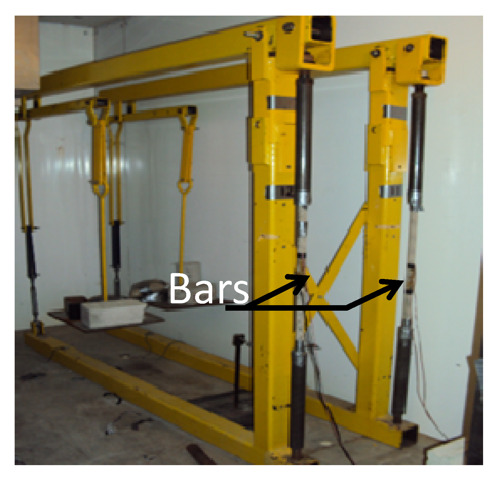
2. Experimental Section
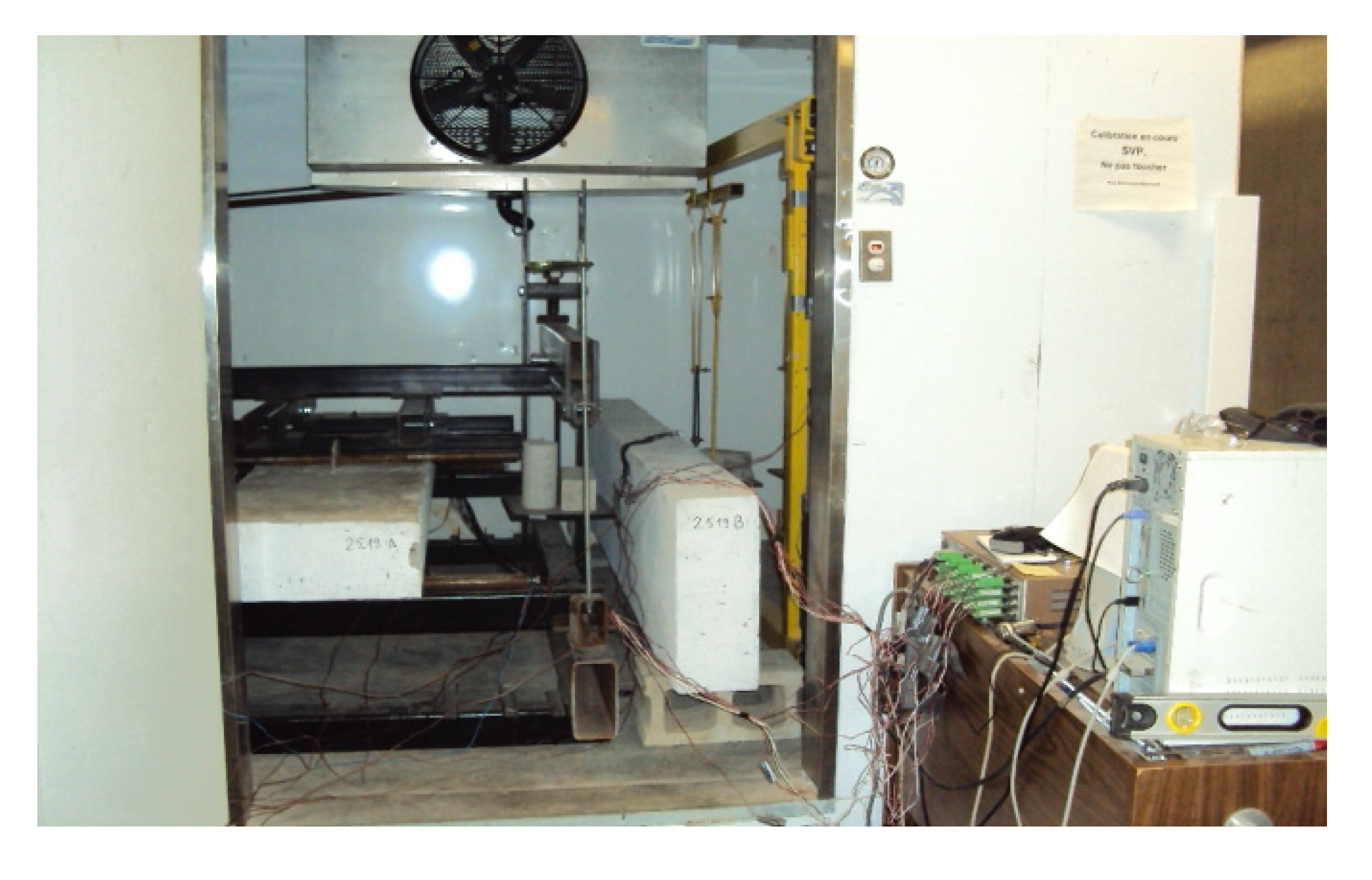
2.1. Description and Instrumentation of Slabs

| Slabs | Concrete cover, c (mm) | Bar diameter db (mm) | c/db | Longitudinal modulus of elasticity, EC (GPa) | Compression strength (MPa) | Tensile strength (MPa) |
|---|---|---|---|---|---|---|
| SA195.25.16 | 25 | 15.9 | 1.57 | 26.17 ± 0.4 | 33.83 ± 1 | 1.94 ± 0.04 |
| SA200.30.16 | 30 | 15.9 | 1.88 | 24.80 ± 0.8 | 30.39 ± 2 | 2.58 ± 0.04 |
| SA215.45.16 | 45 | 15.9 | 2.83 | 26.17 ± 0.4 | 33.83 ± 1 | 1.94 ± 0.04 |
| SA195.25.19 | 25 | 19.1 | 1.31 | 26.53 ± 0.3 | 34.77 ± 0.7 | 2.77 ± 0.15 |
| SA200.30.19 | 30 | 19.1 | 1.58 | 27.34 ± 0.7 | 36.93 ± 2 | 2.92 ± 0.25 |
| SA215.45.19 | 45 | 19.1 | 2.36 | 27.34 ± 0.7 | 36.93 ± 2 | 2.92 ± 0.25 |

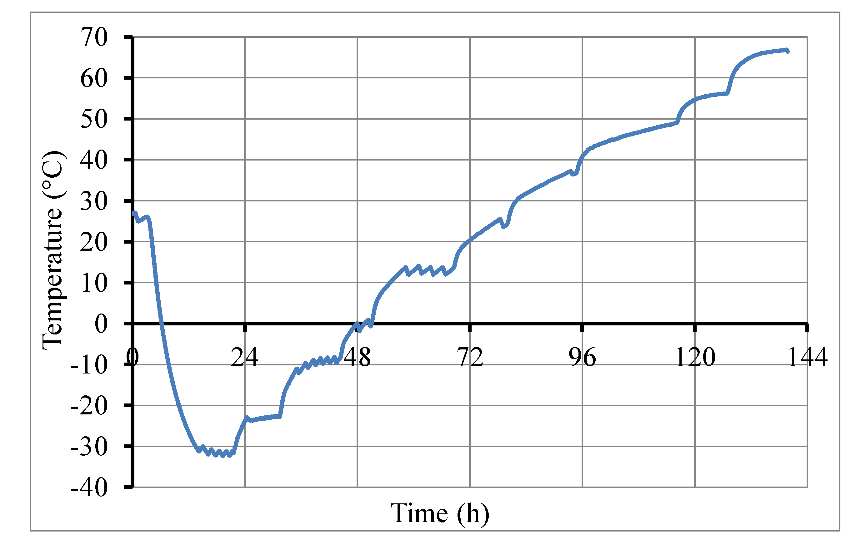
2.2. Test Procedure
2.3. Materials
2.3.1. Concrete
2.3.2. Bars
| Bars diameter db (mm) | 15.9 | 19.1 |
|---|---|---|
| Longitudinal Modulus of elasticity, Efl (GPa) | 47.0 ± 0.3 | 52.2 ± 1.2 |
| Transverse modulus of elasticity, Eft (GPa) | 7.75 | 7.87 |
| Poisson’s ratio in the longitudinal direction, νlt | 0.28 ± 0.005 | 0.28 ± 0.008 |
| Poisson's ratio in the transverse direction, νtt | 0.38 | 0.38 |
| Ultimate tensile strength (MPa) | 700 ± 24 | 691 ± 7 |
| Guarantee tensile strength (MPa) | 683 | 656 |
| Ultimate tensile strain (%) | 1.50 ± 0.06 | 1.33 ± 0.03 |
| TCTE* (αft) [×10−6 ]/°C | 27.35 ± 0.35 | 22.45 ± 0.31 |
| LCTE‡ (αfl) [×10−6]/°C | 6.81 ± 0.9 | 6.61 ± 0.1 |
2.4. Results and Discussion
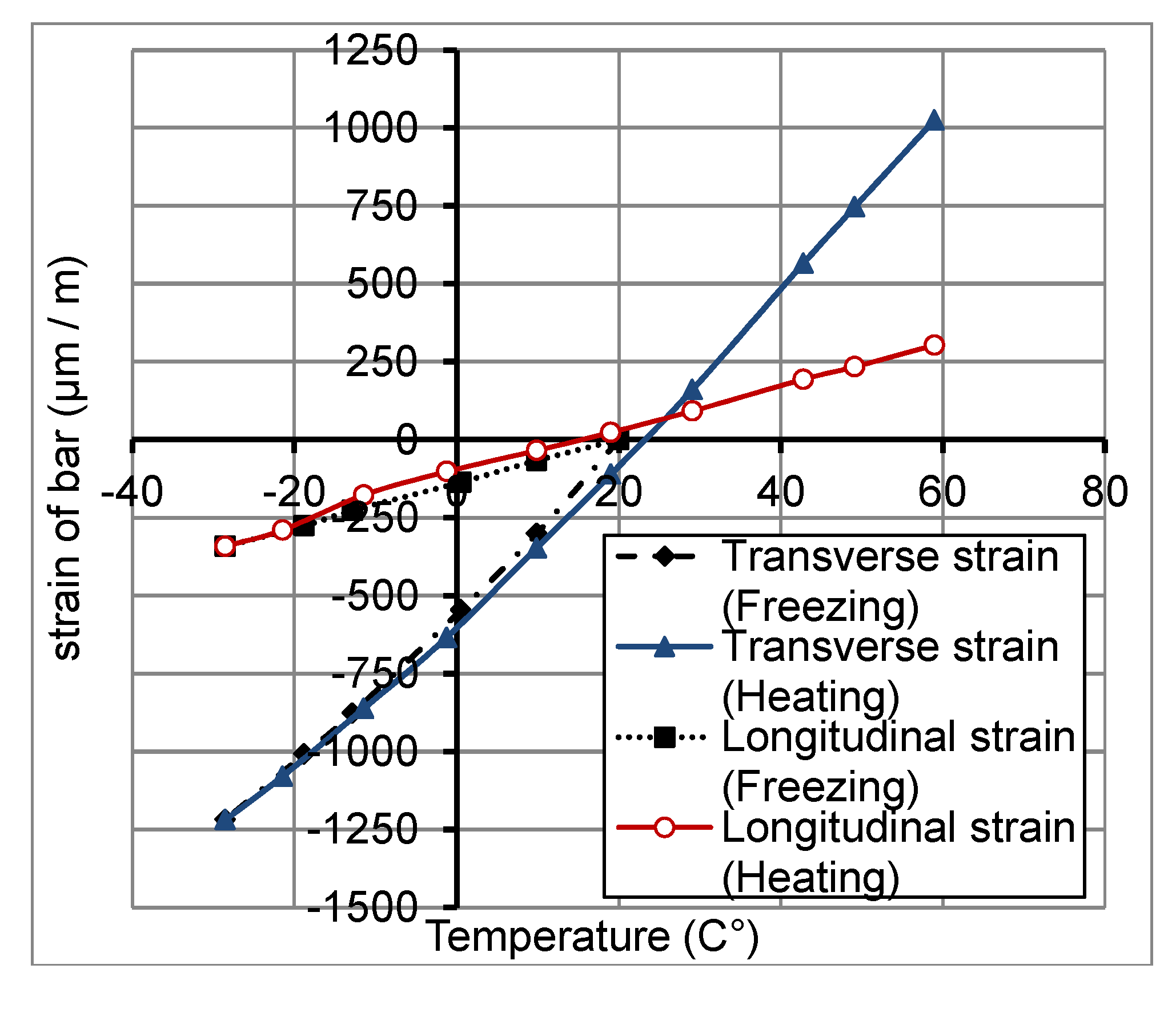
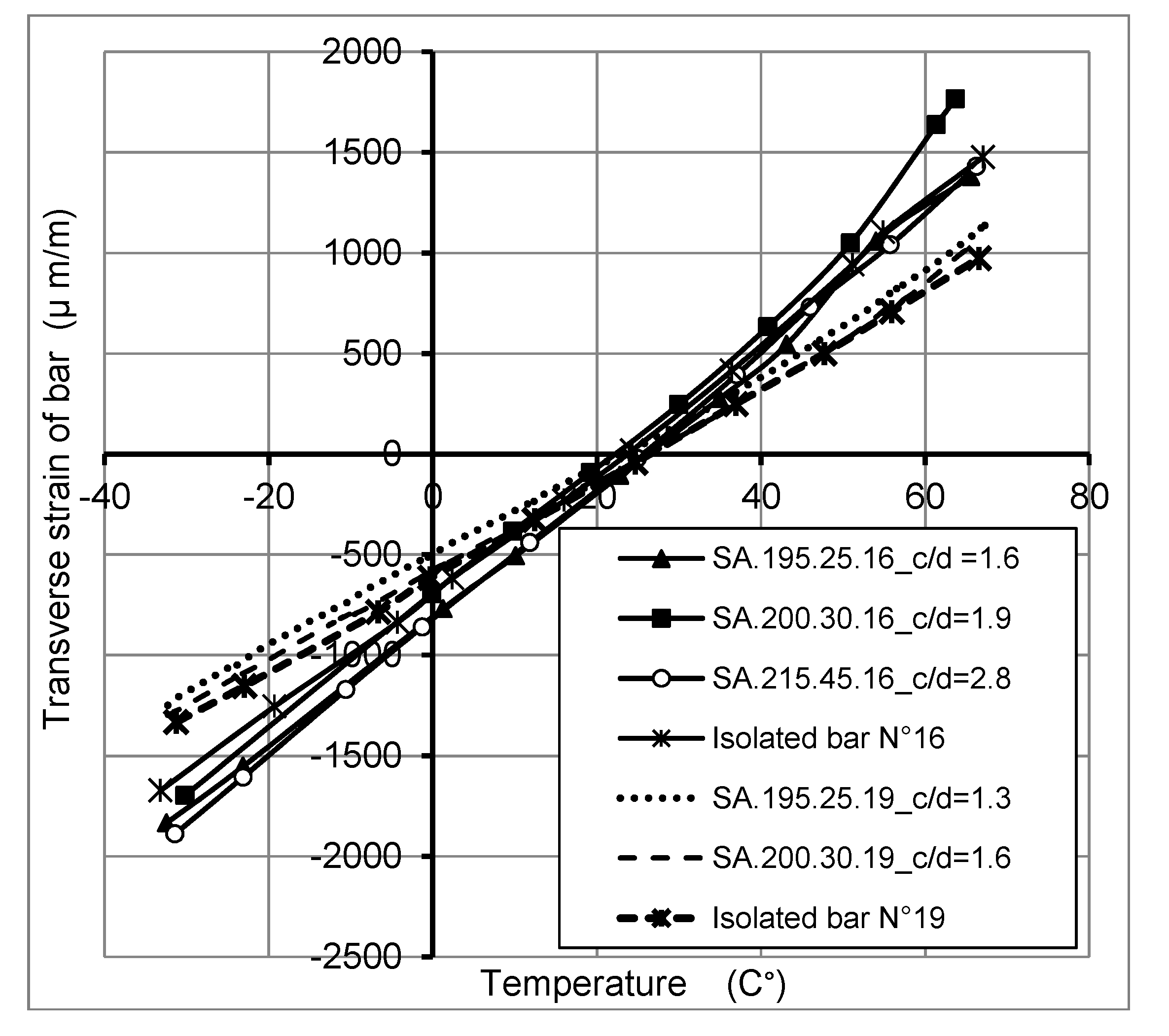
2.4.1. Thermo-Mechanical Behavior of FRP Bars


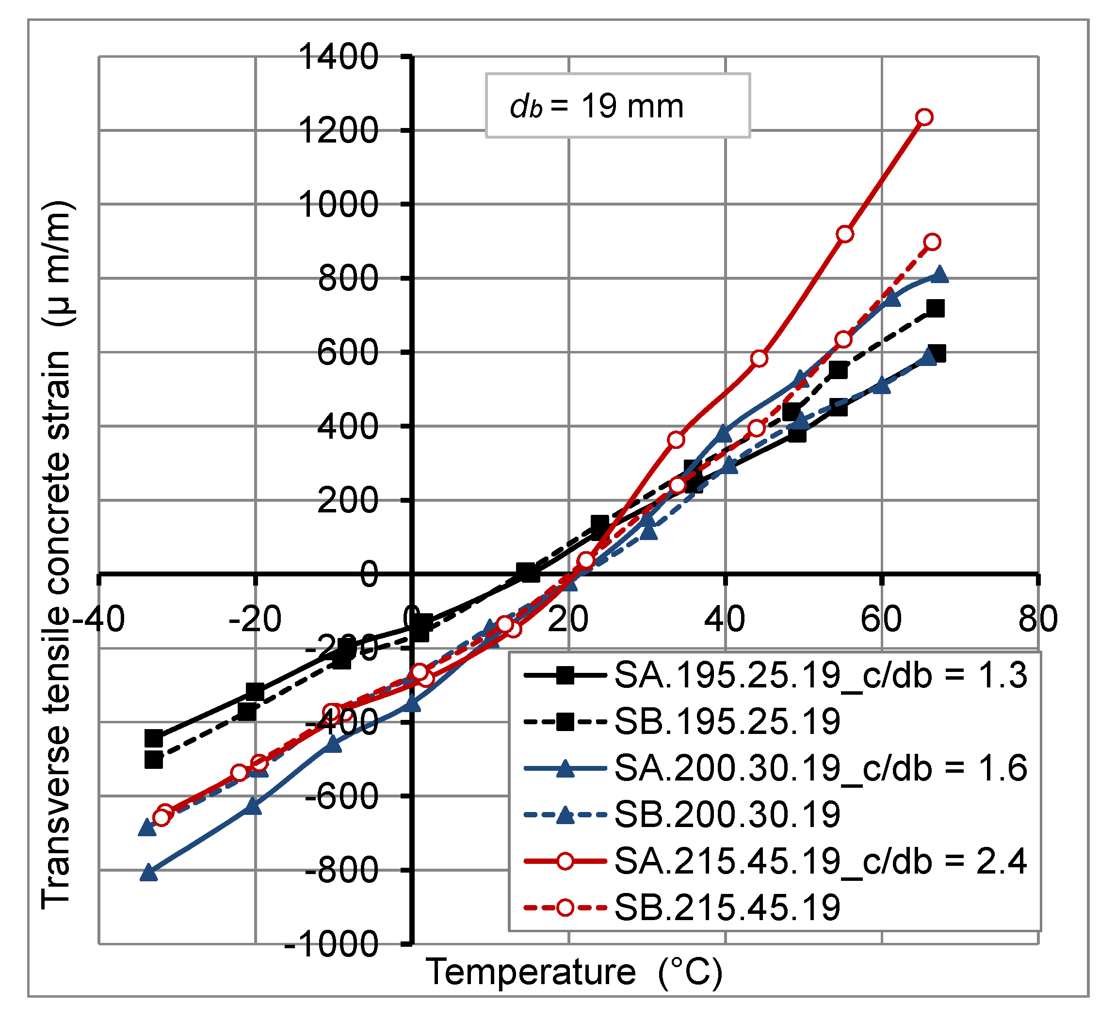
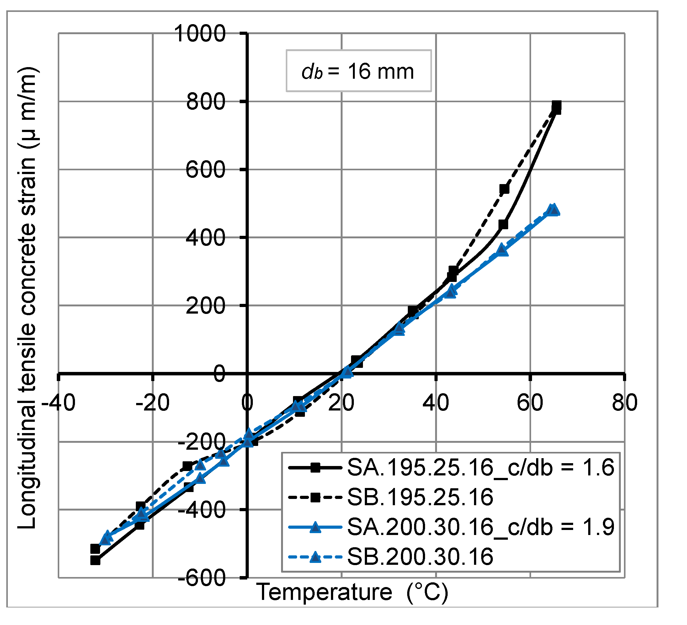
2.4.2. Thermo-Mechanical Behavior of Concrete

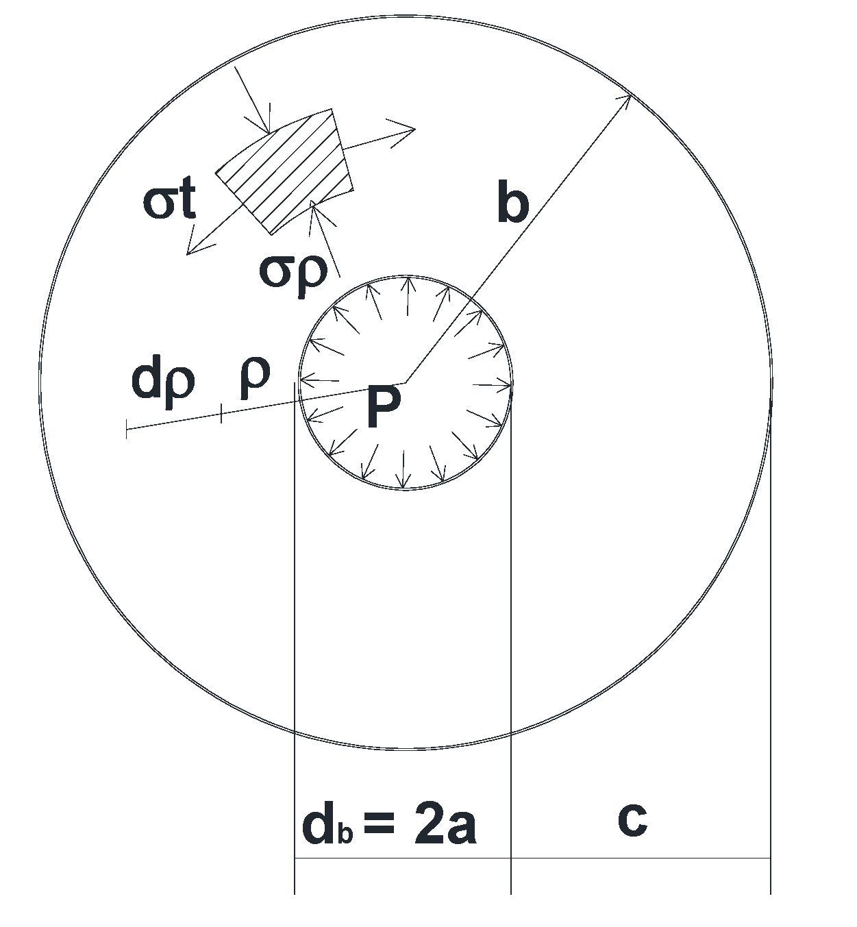
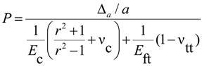
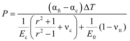
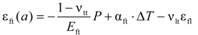
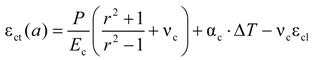
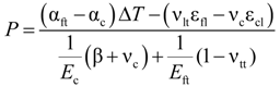
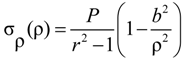
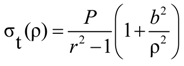
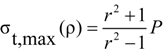
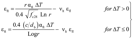
3. Analytical Model
- -
- A perfect bond between concrete and FRP bar.
- -
- The behavior of concrete and FRP bars is linear elastic.
- -
- The cross section of the concrete cylinder remains plane after deformation.
- -
- Absence of transverse reinforcing bars to evaluate only the contribution of the concrete cover to support the tensile stresses due to applied loads.
 .
.

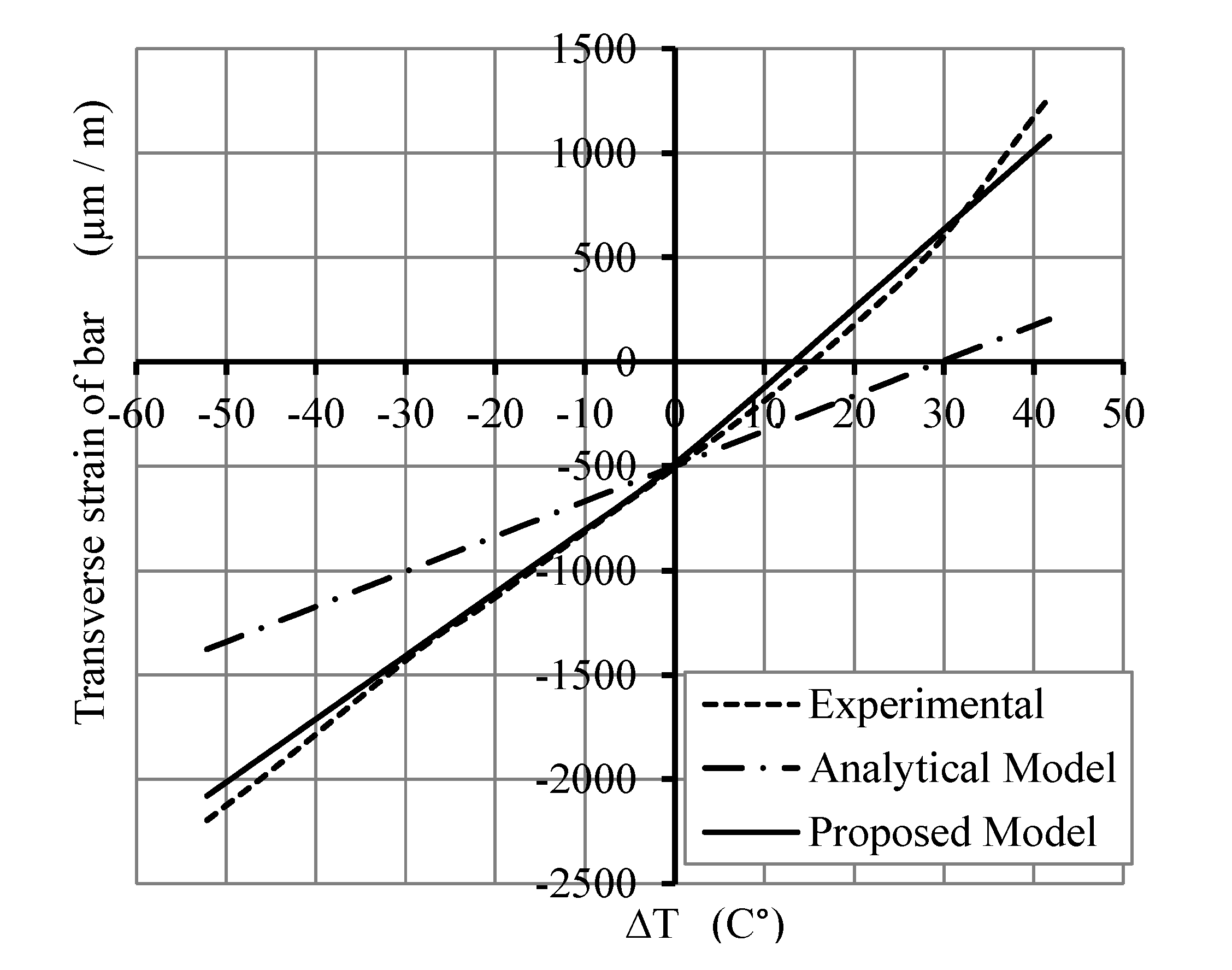
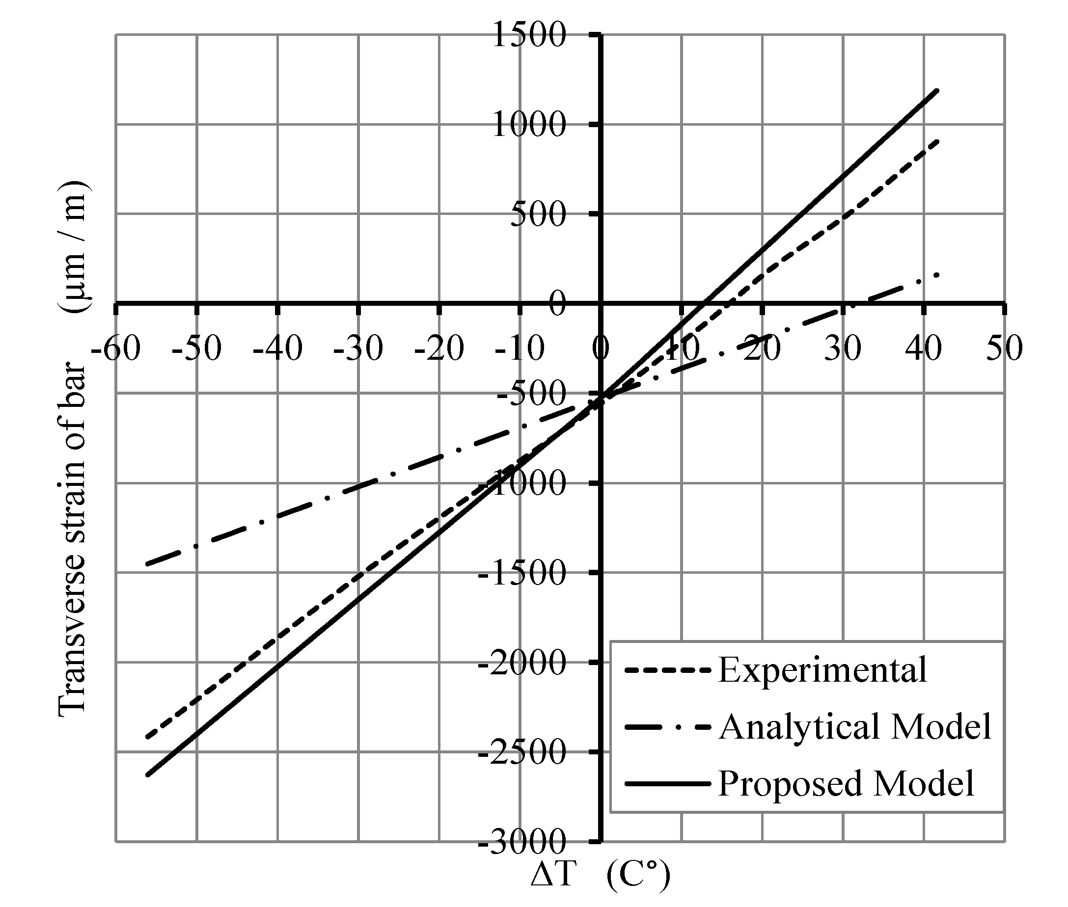
4. Comparison of Analytical and Experimental Results

5. Conclusions
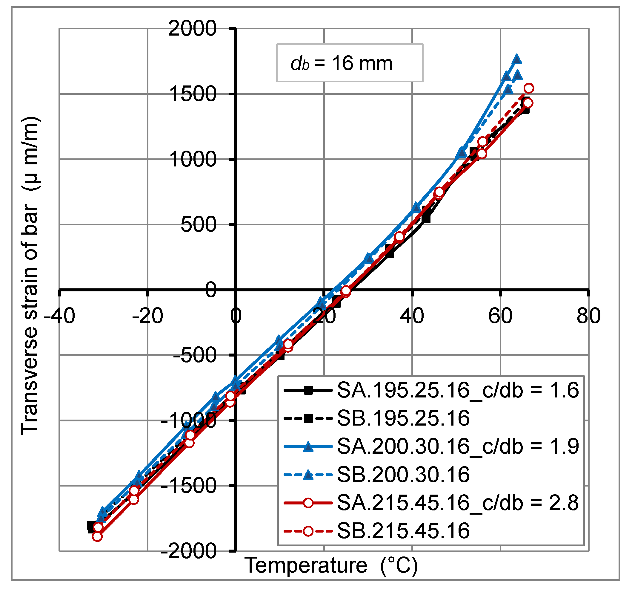
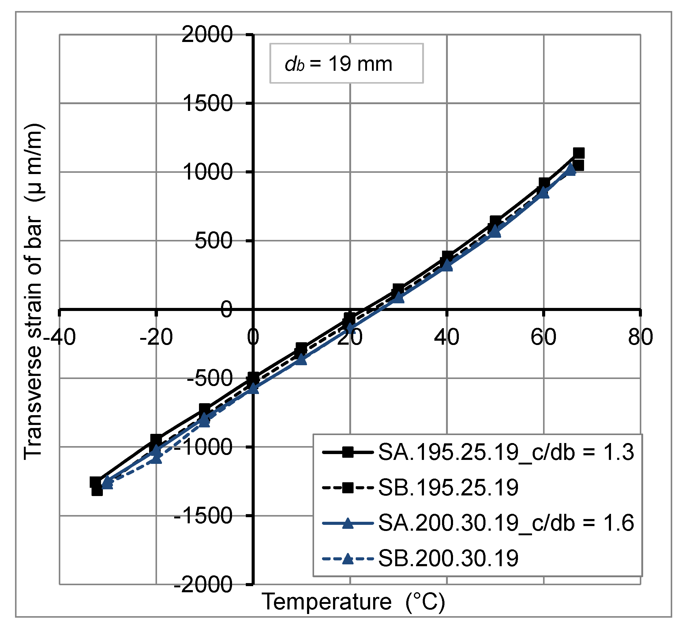
- The mechanical load effect of 20% of the ultimate load (Fu) of reinforced concrete slabs has no significant effect on the transverse thermal strains of GFRP bars embedded in concrete under temperature variation from −30°C to +60°C.
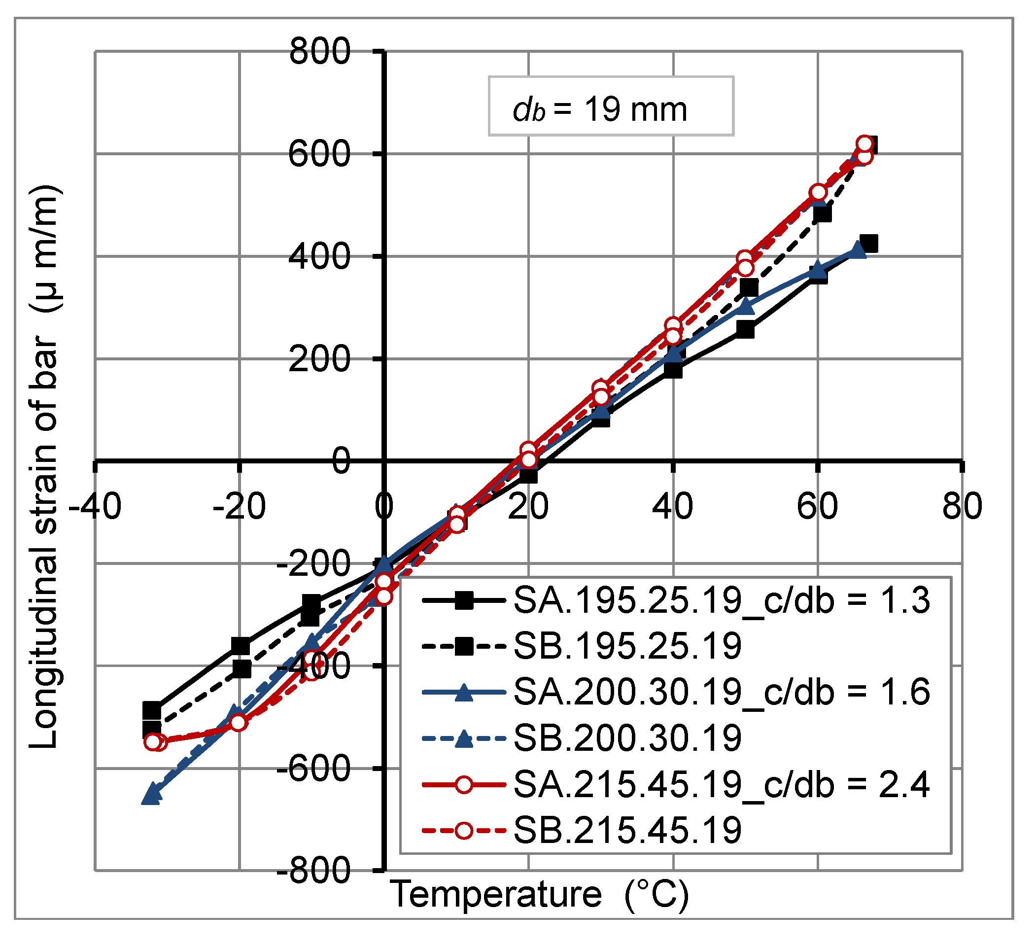
- At high temperature (>40°C), longitudinal thermal strains at the GFRP bar/concrete interface have been reduced under applied mechanical loads. This reduction reached 30%, for a temperature of +60°C, due to the decrease of radial pressure generated at the interface. However, for temperatures variation from −30°C to +40°C, the mechanical load has no big influence on longitudinal thermal strains at the GFRP bar/concrete interface.
- The thermo-mechanical behavior of GFRP bars embedded in concrete of actual slabs is linear elastic.
- The concrete cover thickness variation has no big effect on transverse thermal strains at GFRP bar/concrete interface, for temperature variation from −30 °C to +60 °C. However, the transverse thermal strains decrease with the increase of FRP bar diameter.
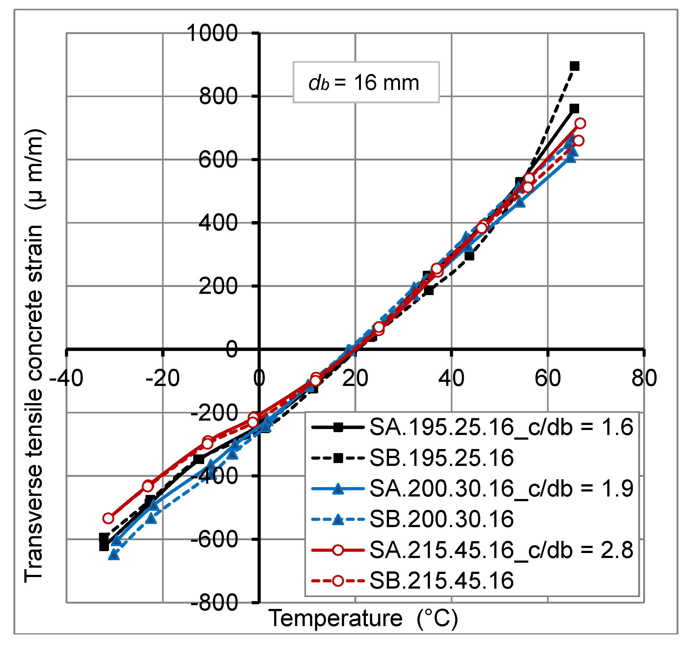
- At high temperature, transverse tensile concrete strains at external surface of concrete cover were reduced under mechanical load. This reduction varied from 5% to 15%, for a temperature of +60 °C, due to the decrease of the radial pressure and consequently the reduction of radial crack propagations through concrete cover. While, for the low temperature (−30 °C), the mechanical load of 20% Fu, has no remarkable effect on transverse tensile concrete strains.
- Ratiosof concrete cover thickness to FRP bar diameter (c/db) varied from 1.3 to 2.8 are sufficient to avoid failure of the concrete cover of GFRP bars—reinforced concrete slabs under combined thermal and mechanical service loads for materials used in this study.
- The transverse strains, at FRP bar/concrete interface of concrete slab under thermal and mechanical loads, predicted from the analytical model are greater than those obtained from experimental tests. This is due to the presence of cracks produced within concrete at the interface which is not considered in the linear analytical model based on the theory of elasticity.
- The transverse strains, at FRP bar/concrete interface, predicted from the proposed model, are in good agreement with experimental results obtained from GFRP bars-reinforced concrete slabs under the combined thermal load (from −30 °C to +60 °C) and mechanical load (20% of the ultimate load of slabs).
Nomenclature
| c | Concrete cover thickness |
| db | FRP bar diameter |
| Ec | Modulus of elasticity of concrete |
| Eft | Modulus of elasticity of FRP bar in the transverse direction |
| fct | Tensile strength |
| Fu | Ultimate load |
| f’c28 | Compressive concrete strength |
| P | Radial pressure |
| r = b/a | ratio of concrete cylinder radius “b” to FRP bar radius “a” |
| αft | Transverse coefficient of thermal expansion of FRP bars |
| αc | Coefficient of thermal expansion of concrete |
| ΔT | Temperature variation |
| εft | Circumferential strains in FRP bar at the interface of FRP bar/concrete |
| εct | Circumferential strains in concrete at the interface of FRP bar/concrete |
| εfl | Longitudinal strain in the FRP bar due only to the mechanical loading |
| εcl | Longitudinal strain in the tensile concrete due only to the mechanical loading |
| νc | Poisson’s ratio of concrete |
| νtt | Poisson’s ratio of FRP bar in the transverse direction |
| νlt | Poisson’s ratio of FRP bar (force applied in longitudinal direction and strains measured in transverse direction) |
| ρ | Radius from the center of the concrete cylinder |
| σρ | Radial stress in concrete cover |
| σt | Circumferential stress in concrete cover |
| σt, max | Maximum circumferential stress in concrete cover |
Acknowledgments
Author Contributions
Conflicts of Interest
References
- Pendhari, S.S.; Kant, T.; Desai, Y.M. Application of polymer composites in civil construction: A general review. Compos. Struct. 2008, 84, 114–124. [Google Scholar] [CrossRef]
- Zaidi, A.; Masmoudi, R. Thermal effect on FRP-reinforced concrete slabs. In Proceedings of 1st International Structural Specialty Conference, CSCE, Alberta, Canada, 23–26 May 2006.
- EL-Zaroug, O.; Forth, J.; Ye, J.; Beeby, A. Flexural performance of concrete slabs reinforced with GFRP and subjected to different thermal histories. In Proceedings of 8th International Symposium on Fiber Reinforced Polymer Reinforcement for Concrete Structures, FRPRCS-8, Patras, Greece, 16–18 July 2007.
- Elbadry, M.; Elzaroug, O. Control of cracking due to temperature in structural concrete reinforced with CFRP bars. Compos. Struct. 2004, 64, 37–45. [Google Scholar] [CrossRef]
- Intelligent Sensing for Innovative Structures (ISIS Canada). Design Manual N°3Reinforcing Concrete Structures with Fibre Reinforced Polymers; ISIS: Winnipeg, Manitoba, Canada, 2007. [Google Scholar]
- Bellakehal, H.; Zaidi, A.; Masmoudi, R.; Bouhicha, M. Combined effect of sustained load and freeze-thaw cycles on one-way concrete slabs reinforced with glass fibre-reinforced polymer. Can. J. Civil Eng. 2013, 40, 1060–1067. [Google Scholar] [CrossRef]
- Canadian Standards Association (CSA). Design and Construction of Building Structures with Fibre-Reinforced Polymers; CAN/CSA S806-12; CSA: Mississauga, Ontario, Canada, 2012. [Google Scholar]
- American Concrete Institute (ACI). Guide Test Methods for Fibre-Reinforced Polymers (FRPs) for Reinforcing or Strengthening Concrete Structures; ACI 440; American Concrete Institute: Farmington Hills, MI, USA, 2004. [Google Scholar]
- Vogel, H.; Svecova, D. Effect of temperature on concrete cover of FRP prestressed elements. In Proceeding of Advanced Composite Materials in Bridges and Structures (IV ACMBS), Alberta, Canada, 20–23 July 2004.
- Rahman, H.A.; Kingsley, C.Y.; Taylor, D.A. Thermal stress in FRP reinforced concrete. In Proceeding of Annual Conference of the Canadian Society for Civil Engineering, Ottawa, Canada, 1–3 June 1995.
- Timoshenko, S.P.; Goodier, J.N. Calcul des cylindres a parois épaisses et disques tournants. In Théorie d’élasticité; Librairie Polytechnique Ch. Béranger: Paris, France, 1961; pp. 514–521. [Google Scholar]
- Masmoudi, R.; Zaidi, A.; Gérard, P. Transverse thermal expansion of FRP bars embedded in concrete. J. Compos. Constr. 2005, 9, 377–387. [Google Scholar] [CrossRef]
- Zaidi, A.; Masmoudi, R. Thermal effect on fiber reinforced polymer reinforced concrete slabs. Can. J. Civil Eng. 2008, 35, 312–320. [Google Scholar] [CrossRef]
© 2014 by the authors; licensee MDPI, Basel, Switzerland. This article is an open access article distributed under the terms and conditions of the Creative Commons Attribution license (http://creativecommons.org/licenses/by/3.0/).
Share and Cite
Bellakehal, H.; Zaidi, A.; Masmoudi, R.; Bouhicha, M. Behavior of FRP Bars-Reinforced Concrete Slabs under Temperature and Sustained Load Effects. Polymers 2014, 6, 873-889. https://doi.org/10.3390/polym6030873
Bellakehal H, Zaidi A, Masmoudi R, Bouhicha M. Behavior of FRP Bars-Reinforced Concrete Slabs under Temperature and Sustained Load Effects. Polymers. 2014; 6(3):873-889. https://doi.org/10.3390/polym6030873
Chicago/Turabian StyleBellakehal, Hizia, Ali Zaidi, Radhouane Masmoudi, and Mohamed Bouhicha. 2014. "Behavior of FRP Bars-Reinforced Concrete Slabs under Temperature and Sustained Load Effects" Polymers 6, no. 3: 873-889. https://doi.org/10.3390/polym6030873