1. Introduction
Fiber reinforced polymers (FRP) have been used in blast mitigations due to their ability to reach high strengths while being lightweight and easily applied. Specifically, tests by Orton
et al. [
1], Kim
et al. [
2], Muszynski and Purcell [
3], Razaqpur
et al. [
4], Wu
et al. [
5] and Lu
et al. [
6] have shown the effectiveness of FRP to strengthen reinforced concrete components for blast. Typically the FRP is applied to the back-face of the concrete element as shown in
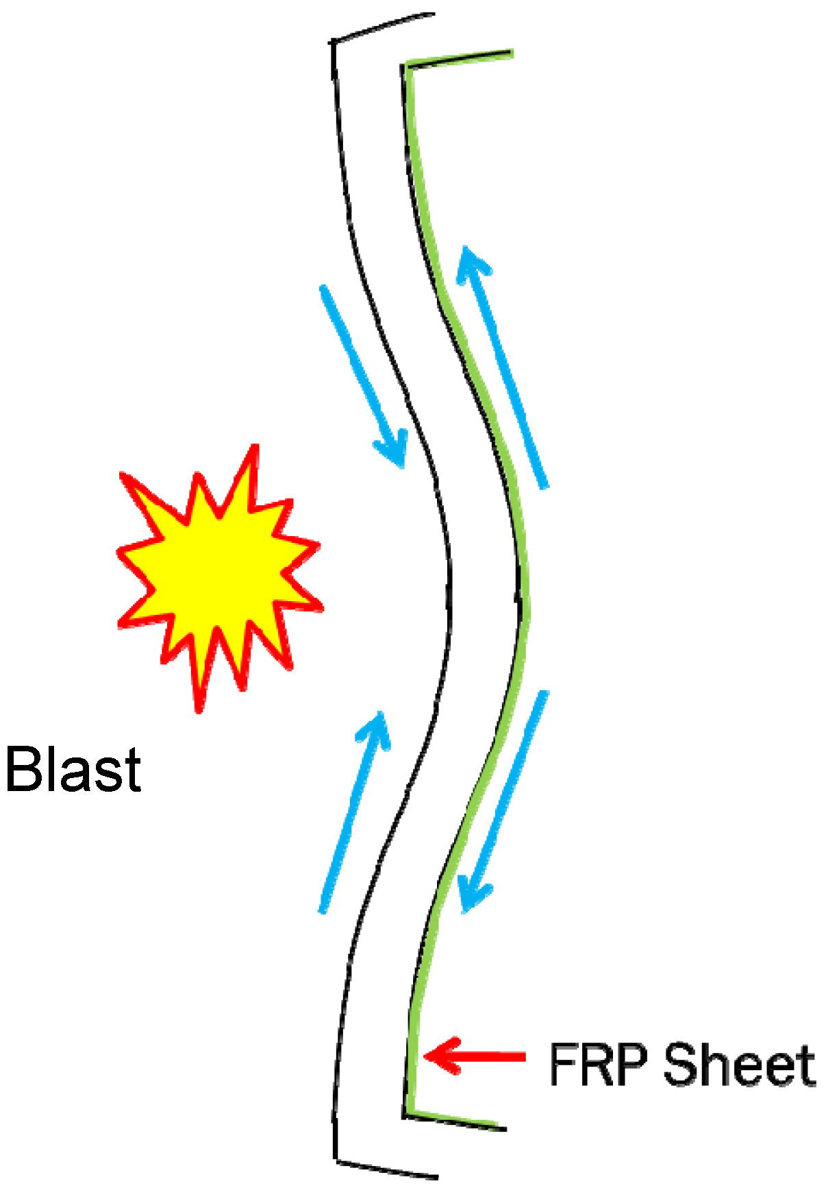
Figure 1. In this configuration the FRP experiences tension due to the bending of the concrete element under the blast. The high strength and lightweight properties allow for the FRP to greatly increase the resistance of a structural member due to these tensile and bending loads, as well as provide a means for reducing fragmentation projectiles while still regulating the amount of mass of the member. This becomes important when considering that the addition of large amounts of mass will increase the overall amount of dead load acting on the columns and foundation of a structure which may approach or exceed their static capacity. However, the question of how the material properties (tensile strength and ductility) of the FRP change at the strain rates applied by blast loading remains unanswered.
Figure 1.
Fiber reinforced polymers (FRP) applied to back-face of reinforced concrete element.
Figure 1.
Fiber reinforced polymers (FRP) applied to back-face of reinforced concrete element.
This research specifically considers wet lay-up carbon based FRP (CFRP) in which carbon fibers are saturated with epoxy and applied to a reinforced concrete element on site. In addition, the research considers strain rates representative of what CFRP would experience if applied to a reinforced concrete element under blast loading. Although a blast is a very impulsive load with durations as low as, or less than, 20 ms, the strain rate actually experienced in the CFRP is a function of the movement of the structure after the blast. Consider a CFRP mitigated concrete slab. When the blast occurs the shock wave will move through the concrete very quickly, but due to the interface between the concrete and CFRP the shock wave is reflected when it reaches the CFRP. Therefore the CFRP is not actually loaded with the blast wave. The loading of the CFRP occurs once the entire slab starts to move in response to the blast. For structures under short impulse loads this movement occurs at a rate equal to the natural period of the system. Therefore the strain rate experienced in the CFRP is dependent on the structural system to which the CFRP is attached. The target strain rate for the CFRP under blast loading for this research is based on the actual blast tests presented in Orton
et al. [
1]. For these tests CFRP mitigated concrete slabs measuring 1.2 m by 2.4 m with a 13 cm thickness were tested under blast loads with a scaled range of 0.4 and 0.6 m/kg
1/3. Following an analysis procedure presented in Biggs [
7] the natural period of the slab is 0.00736 s. If the slab is assumed to deform in a parabolic membrane this means that the strain rate experienced in the CFRP is 1.2 s
−1. Based on high speed video images taken during the actual blast tests the strain rate in the CFRP is approximated to be 3 s
−1 for the 0.4 m/kg
3 scaled range and 0.75 s
−1 for the 0.6 m/kg
3 scaled range. These rates also agree with computational analysis from Mosalam and Mosallam [
8] for farther field blasts which indicate strain rates less than 1 s
−1. Because different structures will have different natural periods and the CFRP will experience different strain rates, the target strain rate range for the coupon tests was set between 1 and 8 s
−1 to be representative a wide range of possible reinforced concrete elements.
It is well known that the rate of loading or strain rate can affect a material’s properties. Standard building materials used in structures such as concrete and steel have shown that they perform very differently dynamically than under normal static loading conditions [
9]. The UFC 3-340-02 [
9] gives dynamic increase factors (DIF) for both steel and concrete to account for the higher strengths reached due to higher strain rates when under a blast scenario. For concrete the DIF starts to increase rapidly above 1.2 once the strain rate exceeds 0.1 s
−1. For steel, the grade of steel is important as higher grades of steel show less strain rate effect and there is a higher DIF for the yield strength than for the ultimate strength. For example, grade 60 reinforcement has a DIF of 1.3 for yield and 1.1 for ultimate strength at a strain rate of 1 s
−1.
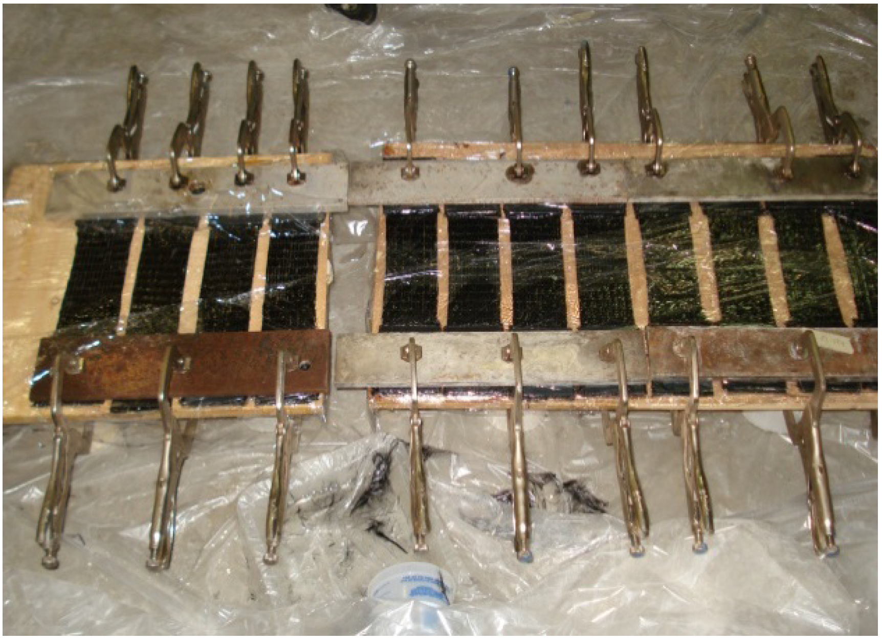
Strain rate may also affect the behavior of CFRP composite materials. However, CFRP made with differing manufacture techniques will have different material properties and therefore different sensitivity to strain rates. Therefore this research considers a type of CFRP that is typically used in the civil industry and may not be comparable to other studies that used a higher quality CFRP common in the aerospace and automotive industries. Furthermore, the CFRP used in this study is made to be applied to reinforced concrete structures using a wet lay-up technique (flexible carbon fiber fabric that is saturated with epoxy at the jobsite). This type of process induces waviness into the material (the surface of the concrete is not perfectly flat) and makes it difficult to control the ratio of carbon fiber to epoxy. Finally, this research will focus on strain rates that might be experienced by CFRP applied to a reinforced concrete member undergoing a blast loading. Although the blast wave loads the structure vary rapidly, the actual rate of strain in the tensile CFRP is much slower.
There have also been numerous studies on fiber reinforced composites, including both CFRP and GFRP (glass fiber reinforced polymer) that points to their viscous nature. Creep in composites has been recognized by many researchers and is primarily due to the matrix supporting stresses in shear deforming under long term loads [
10,
11]. The matrix is also susceptible to changes in behavior under high loading rates. To further establish material characteristics under high strain rates, in 1997 Sierakowski [
12] presented a review of strain rate effects in several different types of composites tested using several different test methods. He found that the fiber orientation, composite type, mode of loading, and strain rate all affect the behavior of the material. For hydraulic/pneumatic tests (such as the one used in this research) he noted that strain rates were limited to 10 to 100 s
−1 due to the inertial effects of the load cell and grips and wave propagation effects. Pressure bar tests, such as the Split Hopkinson Pressure Bar, can be used to produce strain rates up to 10,000 s
−1 but can only be used on relatively small samples. In 2004, Jacob
et al. [
13] also conducted a review of strain rate effects in polymer material composites. They found that contradictory conclusions and observations have been reported due in part to differences in testing procedures and specimen sizes. In addition Wisnom [
14] noticed an important size effect in fiber composite materials. He showed that defects and stress gradients will often cause larger size specimens to fail at lower levels of load. This research into strain rate effects of CFRP is focused on the particular case where the CFRP is applied to a reinforced concrete element experiencing a blast loading. Therefore, the CFRP coupon size has been kept large and made with the same wet lay-up technique used in the application of the CFRP to the concrete in order to best represent the strength of the CFRP in service. Furthermore, the target strain rate range is between 1 and 8 s
−1, which is the predicted range of strain rates seen in the CFRP. A hydraulic tension loader was chosen because it could best apply the loads in the strain rate range under question.
In general, previous research has shown that there is some strain rate effect with FRP materials. Welsh and Harding [
15] conducted high strain rate tests on a variety of composites utilizing a tension bar configuration. Materials examined in these tension tests included carbon, glass, and Kevlar reinforced polyester resins. It was revealed from these tests that there is a clear effect of strain rate on the ultimate strength of the materials investigated. For the CFRP specimen the tensile strength increased by 50% over the static strength at a strain rate of 10 s
−1. The other significant observation made from this series of tests was of the fracture appearance of the specimens differed at the various dynamic loading rates. Al-Salehi
et al. [
16] also tested glass, Kevlar, and carbon fibers and found that for strain rates around 20 s
−1 the tensile strength was not significantly greater than the static strength but for strain rates of around 100 s
−1 increases of 70% were noted. Gilat
et al. [
17] further evaluated strain rate effects in carbon/epoxy composites under tensile loading by testing laminates with various fiber orientations. He found that the strain rate effects were more pronounced in composites with 45° fiber orientations due to greater influence of the resin (matrix) behavior.
There have also been studies using glass FRP (GFRP). Shokrieh and Omidi [
18] studied a unidirectional glass/epoxy composite system through the use of a servo-hydraulic test apparatus, specimens over strain rates that ranged from 0.001 to 100 s
−1. Their research showed that the tensile strength of the GFRP increased at around 8 s
−1. Furthermore, in the lower strain rate range, the fracture surface showed minimal damage and only affected small portions across the specimen width. When the strain rate was increased to higher magnitudes, the damage tended to cross the entire specimen width showing extensive debonding between the fibers and the matrix. Asprone
et al. [
19] also studied GFRP composites and found tensile strengths increasing by approximately 5% to 15% starting at around 10 s
−1 strain rates.
Therefore, the previous research shows that there are some strain rate effects in GFRPs at around 8 s−1. Whereas for CFRPs the point at which strain rate affects tensile strength may occur around 10 or 20 s−1. In addition, it is important to note that these tests were not performed on the same type of CFRP as used in this research and were often performed on very small samples of CFRP in a tension bar configuration, therefore there may or may not be a strain rate effect at rates CFRP would see in a blast event.
3. Results and Discussion
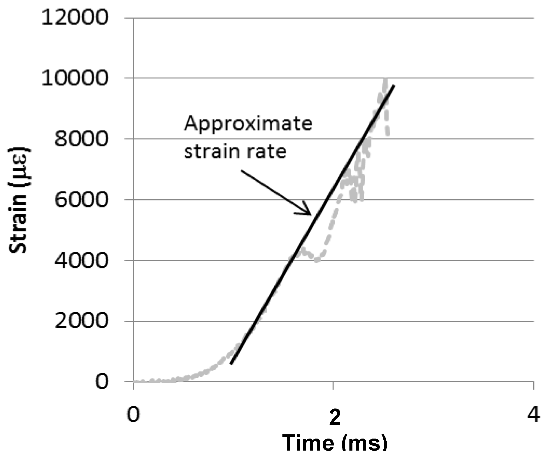
Testing of 21 carbon/epoxy coupons occurred in the dynamic loaded mentioned previously. Due to the impulsive nature of the loading the actual rate of loading and strain is not controlled and depends on the response of the test specimen. The strain and loading rates of the test specimens were determined by finding the approximate rate from the time in which the load or strain began to increase until the point of fracture. An example is shown in
Figure 6 where the slope of the lines indicates the strain rate. The average strain rate is the average of the approximate rates determined from the three strain gages. Considerably different strains in the three strain gages would indicate misalignment of the coupon and therefore and induced moment. Therefore, coupons in which the strain at failure differed by more than 20% were removed from the analysis. Loads from the three load cells were generally in agreement therefore only the load measured in the upper 222 kN cell is presented.
Figure 6.
Determination of approximate strain rate.
Figure 6.
Determination of approximate strain rate.
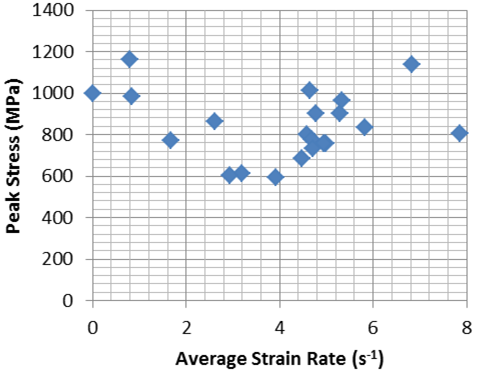
Overall results of the coupon tests can be seen in
Figure 7 and
Table 2. Test data shows no increase in coupon tensile strength at strain rates less than 8 s
−1. However, there is significant variability in the strengths obtained at the different strain rates. The average strength of all the coupons is 840 MPa with a standard deviation of 161 MPa. The ultimate tensile strength is less than the manufacture’s reported 986 MPa as presented in
Table 1. Three coupons that were tested at near static rates (#15, #17 and #18) had an average tensile strength of 1047 ± 99 MPa which is in line with the manufacture’s reported static properties. Therefore, the entire set of coupons tested dynamically showed on average 24% less tensile strength with almost 1.6 times the standard deviation than the static coupons. Testing of 7 additional coupons with only a 4 cm width in a static testing machine yielded an average tensile strength of 882 ± 92 MPa. The average strength of the seven additional coupons is closer to the dynamically tested coupons; however the standard deviation of the coupons strengths is 60% less. The reduction in standard deviation of the statically loaded coupons would seem to indicate that dynamic loading can lead to more variability in the coupon strength. Previous research indicated that the failure surface of dynamically loaded CFRP differed than that of statically loaded CFRP [
13]. Higher loading rates may result in an inability to fully distribute load among the fibers leading to premature failure in some dynamically tested coupons. Furthermore, the coupons tensile strength is on average less than the manufacture’s reported value. This may be due to the wet lay-up manufacture of the coupons which most closely resembles the field application of the material. The wet lay-up manufacture could lead to additional waviness of the fibers thereby reducing the overall tensile strength.
Figure 7.
Peak stress vs. average strain rate for all coupons.
Figure 7.
Peak stress vs. average strain rate for all coupons.
Table 2.
Test Results.
| Sample# | S1 | S2 | S3 | Average Strain Rate (s−1) | Peak Stress (MPa) | Loading Rate (MPa/ ms) | Type of Fracture |
|---|
| Max Strain (E−6) | Strain Rate (s−1) | Max Strain (E−6) | Strain Rate (s−1) | Max Strain (E−6) | Strain Rate (s−1) |
|---|
| 1 | na | 10,995 | 6.84 | na | 6.84 | 1,137 | 690 | Straight |
| 2 | na | 8,414 | 8.71 | 7,076 | 7.01 | 7.86 | 805 | 808 | Split |
| 3 | na | 8,738 | 5.50 | 6,192 | 5.09 | 5.30 | 900 | 578 | Split |
| 4 | na | 5,493 | 2.99 | 7,081 | 4.84 | 3.91 | 593 | 277 | Split |
| 5 | 7,260 | 5.51 | 8,230 | 5.63 | 10,677 | 6.37 | 5.83 | 832 | 602 | Jagged |
| 6 | 6,868 | 4.39 | 6,591 | 4.41 | 9,107 | 4.95 | 4.58 | 799 | 505 | Jagged |
| 7 | 7,307 | 4.12 | 8,259 | 4.84 | 10,446 | 6.04 | 5.00 | 756 | 376 | Jagged |
| 8 | 7,468 | 5.71 | 5,846 | 3.57 | 9,402 | 4.80 | 4.70 | 774 | 371 | Split |
| 9 | 6,164 | 4.42 | 7,872 | 4.98 | 9,829 | 5.43 | 4.94 | 755 | 418 | Jagged |
| 10 | 9,015 | 4.92 | 8,946 | 5.57 | 9,269 | 5.49 | 5.33 | 962 | 589 | Straight |
| 11 | 10,342 | 4.12 | 11,150 | 5.35 | 10,781 | 4.44 | 4.64 | 1,011 | 421 | Jagged |
| 12 | 6,498 | 3.17 | 5,263 | 2.94 | 5,084 | 3.49 | 3.20 | 611 | 372 | Split |
| 13 | 10,146 | 2.86 | 7,970 | 2.45 | 7,624 | 2.51 | 2.61 | 862 | 235 | Straight |
| 14 | na | 6,377 | 2.96 | 7,913 | 2.90 | 2.93 | 604 | 243 | Jagged |
| 15 | 11,150 | 2.96 | 11,226 | 0.80 | 10,106 | 0.74 | 0.79 | 1,162 | 78 | Jagged |
| 16 | 9,240 | 0.83 | 8,136 | 1.64 | 8,507 | 1.71 | 1.67 | 771 | 144 | Straight |
| 17 | 9,852 | 1.66 | 10,227 | 0.84 | 10,244 | 0.86 | 0.84 | 983 | 86 | Jagged |
| 18 | 9,223 | 0.01 | 9,846 | 0.01 | 8,038 | 0.00 | 0.01 | 997 | 0.54 | Straight |
| 19 | 8,305 | 4.75 | 9,096 | 5.06 | 7,630 | 4.51 | 4.78 | 901 | 500 | Straight |
| 20 | 8,744 | 4.16 | 6,158 | 3.69 | 11,081 | 5.59 | 4.48 | 685 | 369 | Jagged |
| 21 | 8,547 | 5.31 | 7,064 | 4.63 | 5,771 | 4.18 | 4.71 | 734 | 506 | Straight |
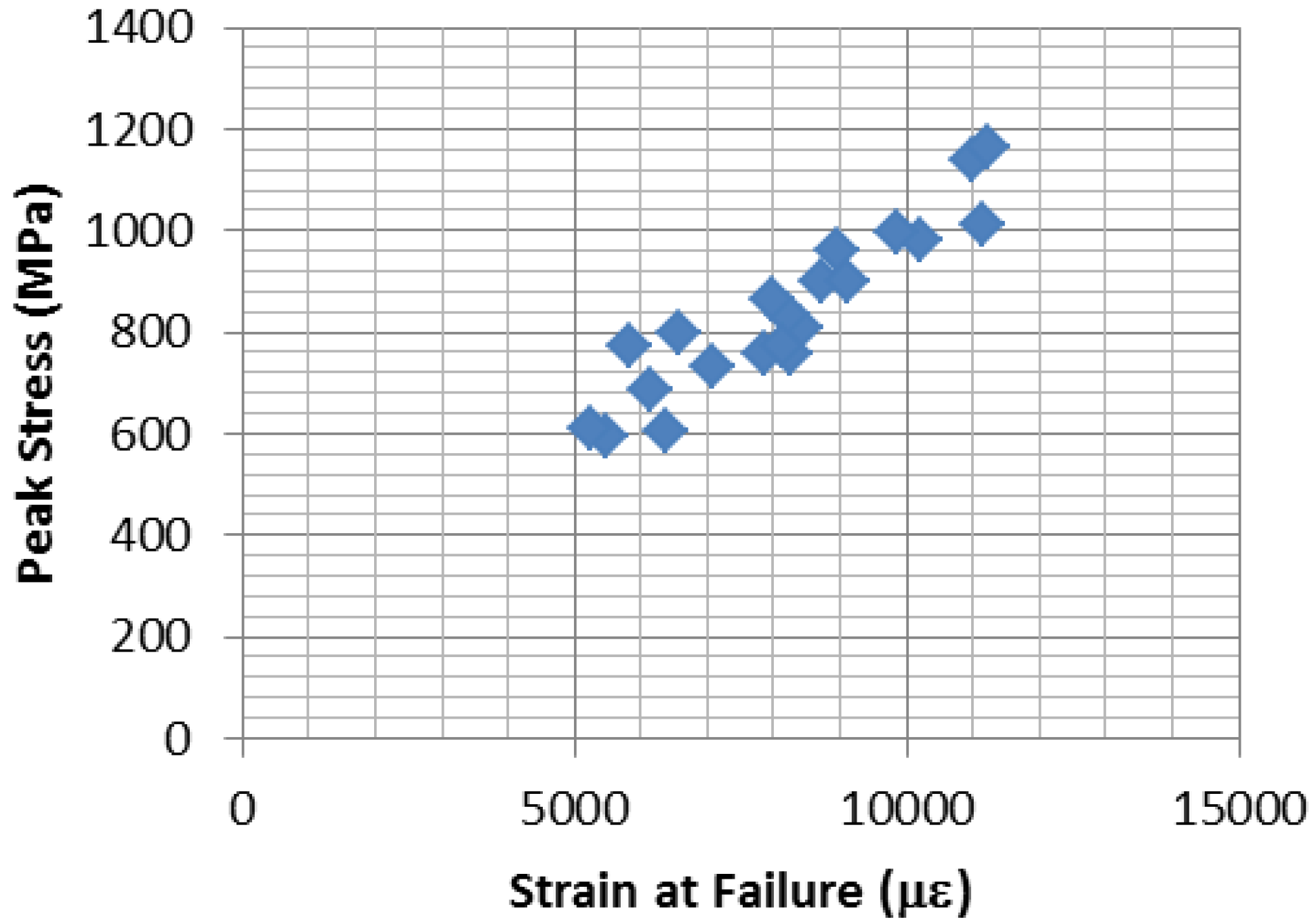
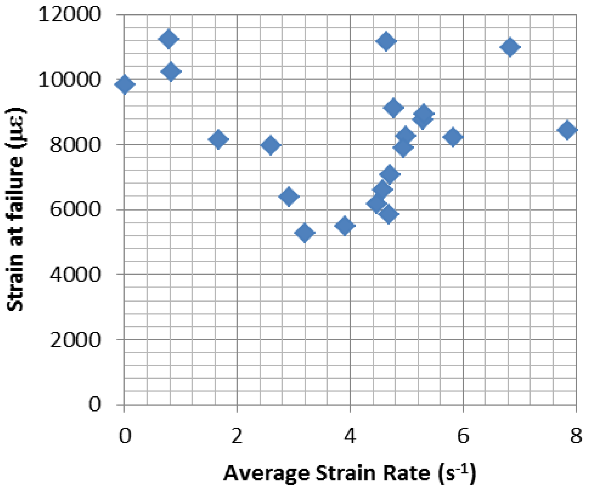
Figure 8 shows when the strain at failure and failure load is compared for all the coupons that the coupons that failed at low levels of load also did so at lower levels of strain as expected with a linear elastic brittle material such as CFRP. Therefore, the coupons that had lower ultimate tensile load levels were not able to achieve their full average strain capacity before failure. There was likely some failure in some fibers of the coupon early on that lead to the total fracture of the coupon.
Figure 8.
Strain at failure vs. peak stress.
Figure 8.
Strain at failure vs. peak stress.
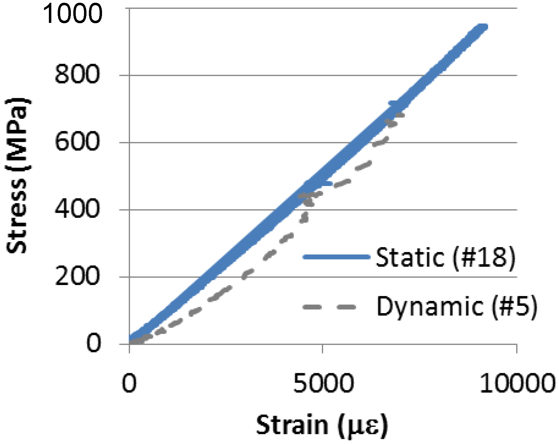
In addition, it can be seen that there is no significant change in stiffness under dynamic loading.
Figure 9 illustrates the stress strain curve for statically tested Coupon #18 and dynamically tested Coupon #5. Both curves show the overall linear stress strain behavior expected of a CFRP coupon, however, the dynamic coupon does not illustrate the strictly linear behavior of the statically tested coupon. The static coupon modulus of 103.6 is 10% greater than the dynamic coupon modulus of 92.9 GPa. The average tensile modulus of all the coupons is 96.7 GPa which is close to the manufacture’s reported 95.8 GPa.
Furthermore, there is indication of minor reduction of strain at failure (or elongation at break) for the dynamically tested coupons.
Figure 10 shows the strain at failure based on strain gage 2
vs. the average strain rate. For the dynamically loaded coupons the average strain at failure is 0.008 with a standard deviation of 0.0018. The manufactures’ reported strain at failure and the average for the statically tested coupons is 0.01, which is 20% greater than the dynamically tested coupons.
Figure 9.
Stress vs. strain graph for static and dynamic coupon.
Figure 9.
Stress vs. strain graph for static and dynamic coupon.
Figure 10.
Strain at failure vs. average strain rate.
Figure 10.
Strain at failure vs. average strain rate.
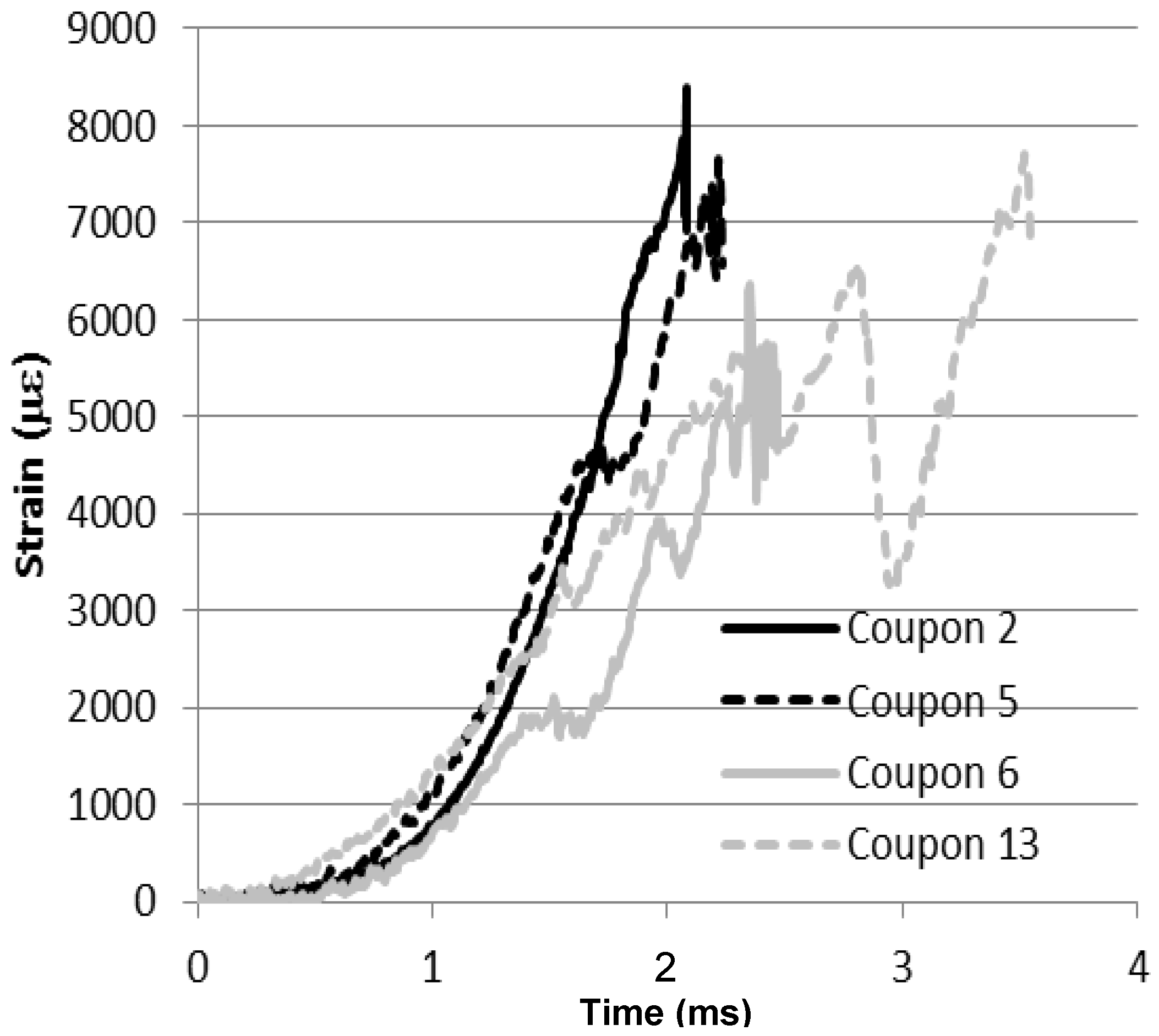
Figure 11 shows representative strain
vs. time graphs for four coupons at different strain rates. The strain data in these graphs comes from strain gage 2 which was located in the center of the specimen. Coupon #2, 5, 6, and 13 had approximate strain rates of 7.86, 5.83, 4.58 and 2.61 s
−1, respectively. As can be seen in the figure, the actual strain rate of the tests varied due to the response of the specimen in the dynamic loader. Coupon #13, which had the lowest approximate strain rate, dipped in the strain time response just before failure of the coupon. This dip is likely due to the movement and dynamics of the specimen and loader during testing. Despite of the dip, Coupon #13 had the highest strength of the four coupons.
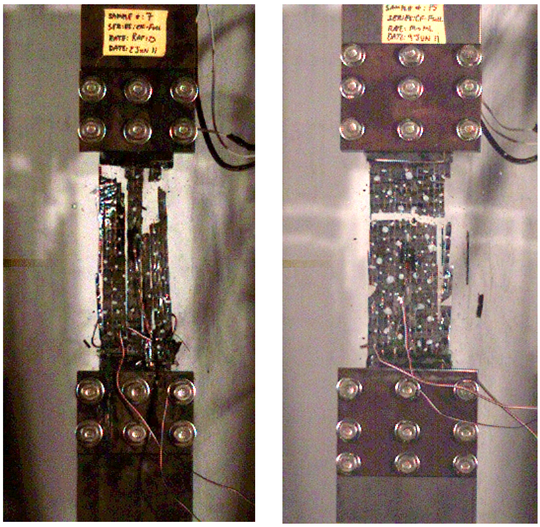
Figure 12 shows high speed stills of Coupon #5 and #13. As seen for Coupon #5 the specimen nearly exploded upon failure, fracturing into several pieces. For Coupon #13 the specimen exhibited a more straight failure across the center of the coupon.
Table 2 summarized the failures as “jagged” similar to Coupon #5 where fibers fractures in different locations, “straight” similar to Coupon #13 where a single horizontal fracture line crossed all fibers, and “split” where a two horizontal fracture lines crossed the specimen in two different locations.
Figure 11.
Strain vs. time graphs for four representative coupons.
Figure 11.
Strain vs. time graphs for four representative coupons.
Figure 12.
High speed failure stills of Coupon #5 (left) and Coupon #13 (right).
Figure 12.
High speed failure stills of Coupon #5 (left) and Coupon #13 (right).

 ,
, 


