Article

Behavior of FRP-Confined Concrete-Filled Steel Tube Columns

School of Civil Engineering, Wuhan University, Wuhan 430072, China
*
Author to whom correspondence should be addressed.
Polymers 2014, 6(5), 1333-1349; https://doi.org/10.3390/polym6051333
Submission received: 30 March 2014 / Revised: 1 May 2014 / Accepted: 5 May 2014 / Published: 8 May 2014
(This article belongs to the Special Issue Fiber-Reinforced Polymer Composites in Structural Engineering)

Abstract

:
This paper presents the results of an experimental study into the behavior of concrete-filled steel tube columns confined by fiber-reinforced polymer (FRP). Eleven columns were tested to investigate the effects of the FRP layer number, the thickness of the steel tube and concrete strength on their load capacity and axial deformation capacity. The experimental results indicated that the FRP wrap can effectively confine the concrete expansion and delay the local buckling of the steel tube. Both the load capacity and the axial deformation capacity of concrete-filled steel tube columns can be substantially enhanced with FRP confinement. A model is proposed to predict the load capacity of the FRP-confined concrete-filled steel tube columns. The predicted results are generally in good agreement with the experimental ones obtained in this study and in the literature.

1. Introduction

Concrete-filled steel tube (CFST) columns have been widely used in modern structural systems. In the CFST columns, the inward buckling deformations of the steel tube can be prevented by the concrete core, but inelastic outward local buckling can result in the degradation of steel confinement, strength and ductility [1,2]. To overcome this deficiency, Xiao [3] used additional transverse confinement outside the steel tube to constrain its outward local buckling. Additionally, this novel form of CFST column was defined as confined concrete-filled steel tube (CCFST) columns. The additional transverse confinement can be carried out by steel tube segments or fiber-reinforced polymer (FRP) wrap.
Fiber composite materials have attracted much attention, due to the advantages of the high strength-to-weight ratio, non-corrosion and flexibility in adapting to field configurations. Their applications in strengthening or retrofitting structures have been demonstrated to be of economic and engineering advantage [4,5]. As a result of the additional confinement from FRP wrap, the outward buckling deformation of the steel tube is mitigated or even eliminated, and the concrete core is further confined [6].
To improve the structural behavior of CFST columns, several researchers have studied the effectiveness of the FRP confinement. Hu et al. [7] performed compressive tests on the FRP-confined concrete-filled steel tube (FCCFST) columns. They studied the parameters of the thickness of the steel tube and the FRP layer number. The results indicated that the FRP wrap could substantially delay or even completely suppress the development of local buckling deformation in the steel tube. The behavior of the concrete was significantly enhanced by the FRP confinement. Sundarraja and Prabhu [8] investigated CFST columns strengthened with carbon fiber-reinforced polymer (CFRP) sheets or CFRP strips. The CFRP layer number and the width and spacing of the strips were studied. The results showed that the external bonding of CFRP not only provided additional confinement pressure to the concrete core, but also constrained the local buckling of the steel tube. Tao et al. [9] studied the compressive behavior of FCCFST columns with a circular and rectangular cross-section. In the circular columns, when the number of the CFRP layers increased, the load capacity increased, but the ductility decreased. In rectangular columns, with the increasing of the CFRP layer number, load capacity had no obvious changes, but the ductility could be improved. There are more experimental and analytical studies on the compressive behavior of the CFST columns strengthened with FRP in [10,11,12]. To obtain a further understanding of the confining mechanism of FRP wrap in FCCFST columns, Teng et al. [13] developed a stress-strain model for concrete in FCCFST columns under compression through theoretical analysis. The strain efficiency of FRP jackets in FCCFST columns under axial compression was studied through nine tests and finite element modeling by Li et al. [14].
Besides the research on the compressive behavior of FCCFST columns, the behavior of FCCFST columns subjected to dynamic loadings has also been studied. Che et al. [15] investigated the seismic behavior of CFST columns wrapped with CFRP in both transverse and longitudinal directions. The concept of the FCCFST column for square section was validated by experimental tests under seismic loads [16]. The square FCCFST columns exhibited significantly improved seismic performance with large ductility. Moreover, the behaviors of FCCFST columns under shear load [17], high speed impact [18,19] and cycle axial load [20] have been investigated. In addition to strengthening the CFST columns in new construction, FRP have also been used to repair CFST columns, such as columns after exposure to fire [21].
The previous studies described above have demonstrated that the FRP confinement provides an effective solution for strengthening CFST columns. In this paper, more research is done to further understand the behavior of FCCFST columns. Specifically, eleven columns were tested to study the parameters of the FRP layer number, the thickness of the steel tube and the concrete strength. The axial load-axial shortening, axial load-axial strain and axial load-hoop strain relationships were measured from the tests. Furthermore, the ultimate loads of the FCCFST columns and the failure modes were also obtained from the tests. The effects of the tested parameters on the ultimate load and the axial shortening capacity are studied in this paper. In addition, the behavior of the confined concrete and the efficiency of FRP wrap are also discussed. A simple model is proposed to calculate the load capacity of FCCFST columns. The predictions are compared with the experimental results in this study and in the literature.

2. Experimental Program

2.1. Test Specimens

A total of eleven specimens, including seven CFRP-confined concrete-filled steel tube (CFCCFST) specimens, three glass fiber-reinforced polymer (GFRP)-confined concrete-filled steel tube (GFCCFST) specimens and one CFST specimen, were tested under axial load. The tested parameters were the FRP layer number nf (1, 2 and 3), the steel tube thickness ts (3.0, 4.0 and 5.0 mm) and the concrete strength fcu(40, 50 and 60 MPa). Each specimen had a length (L) of 400 mm with a length-to-diameter ratio (L/D) ranging between 3 and 3.5. The details of the columns are provided in Table 1. The nomenclature consists of three items: the letters CF and GF in the first item denote the CFRP-confined specimens and GFRP-confined specimens, respectively, followed by the FRP layer number; the letter t and the following number in the second item indicates the steel tube and its thickness; the letter C (for concrete) in the third item is followed by the nominal concrete strength.
Table 1. Details of the specimens.
SpecimensL (mm)D (mm)FRP typenfts (mm)fcu (MPa)fy (MPa)ξsξf
t4C404001284.044.92480.950.00
CF1t4C40400128CFRP14.044.92480.950.39
CF2t4C40400128CFRP24.044.92480.950.78
CF3t4C40400128CFRP34.044.92480.951.17
GF1t4C40400128GFRP14.044.92480.950.48
GF2t4C40400128GFRP24.044.92480.950.97
GF3t4C40400128GFRP34.044.92480.951.45
CF2t3C40400126CFRP23.044.92430.690.77
CF2t5C40400130CFRP25.044.92421.170.79
CF2t4C50400128CFRP24.054.22480.790.65
CF2t4C60400128CFRP24.060.02480.710.58

2.2. Material Properties

The columns were cast using three different concrete mixtures. Three concrete cubes were tested for each mix design to determine the concrete compressive strength. The average cube strengths (fcu) of the concrete cubes are shown in Table 1.
Seamless steel tube was used as the steel formwork for all columns in this study. Steel tubes with thicknesses of 3, 4 and 5 mm were used to achieve different diameter-to-thickness ratios. The steel tubes of 3 and 4 mm were made by machining the seamless steel tube of 5 mm. The properties of the steel tube were determined by a coupon test. The measured values of yield strength (fy) and elastic modulus (Es) were 248 MPa and 191 GPa.
Carbon fiber and glass fiber were used in this study to provide the confinement. The tensile properties were determined from the tensile tests of flat coupons according to ASTM D3039 [22]. The nominal thickness (tf), ultimate strength (ffu), ultimate strain (εfu) and elastic modulus (Ef) of the CFRP were 0.111 mm, 3550 MPa, 1.34% and 250 GPa, respectively; those of the GFRP were 0.169 mm, 2930 MPa, 2.58% and 109 GPa, respectively.
Epoxy resin based on two-component solvent-free epoxy resin was used in this study. The mixing ratio was 4:1 of component A (resin) and component B (hardener) by weight. The elastic modulus, tensile strength and shear strength provided by the manufacturer were 15 GPa, 35 MPa and 13 MPa, respectively.

2.3. Preparation of Specimens

The circular steel tubes were accurately cut and machined to the required length. The insides of the steel tubes were wire brushed, and deposits of grease and oil were removed. A stiffened end-cap of 10 mm was attached at the base of the steel tube. Concrete was filled in layers and vibrated by a poker vibrator. The specimens were left to cure in the laboratory for 28 days, and then, the CFRP or GFRP was wrapped.
The FRP wrap was formed by using the wet lay-up method with fibers in the hoop direction. The steel tube surface was first cleaned with alcohol, and then, a single continuous fiber sheet was wrapped around the steel tube to form a wrap with the required number of plies, with the finishing end of the fiber sheet overlapping its starting end by 150 mm. A paddler roller was used to squeeze out the air bubbles and ensure a uniform bond thickness.
Prior to testing, the top surface of the concrete core was roughened with a wire brush, and a thin layer of high-strength cement was poured on the roughened surface. This procedure was adopted to minimize the effect of concrete shrinkage, so that the steel tube and the concrete core can be loaded simultaneously during testing.

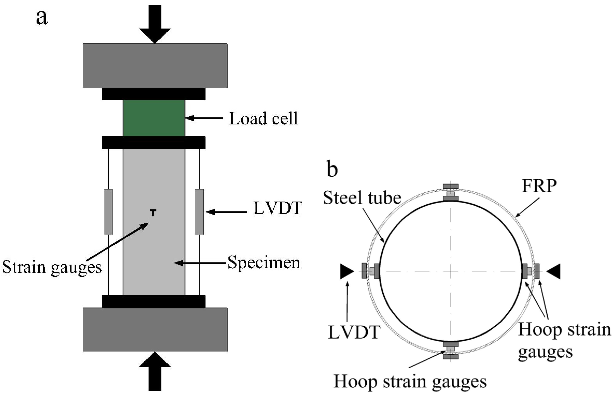
2.4. Test Setup and Instrumentation

The tests were conducted using a universal testing machine with a capacity of 5000 kN. The test arrangement for the specimens is shown in Figure 1a. The load was applied in increments of 50 kN before peak load. Each load interval was maintained for 2–3 min. The load was slowly applied near and after the maximum load to investigate the post-peak behavior of the columns. Two linear variable differential transducers (LVDTs) were located vertically to measure the axial shortening. For each FCCFST specimen, eight strain gauges were placed on the steel to measure the vertical deformations and perimeter expansion of the steel tube at mid-height, and four strain gauges were mounted to the mid-height of the FRP wrap to observe the lateral confinement, as shown in Figure 1b. The layout of the strain gauges mounted to the steel tube of each CFST specimen was exactly the same as that for the FCCFST specimens. To assure uniform compression, preliminary tests within the elastic range were conducted by carefully adjusting the position of the specimen, based on the measurements of strain gauges attached at the mid-height of the test specimen. The adjustment was terminated until the difference between the measured strain and the average value was no more than 5%.
Figure 1. Test arrangement and instruments: (a) test arrangement; (b) layout of strain gauges for fiber-reinforced polymer (FRP)-confined concrete-filled steel tube (FCCFST) specimens. LVDT, linear variable differential transducer.
Polymers 06 01333 g001

3. Experimental Results and Discussions

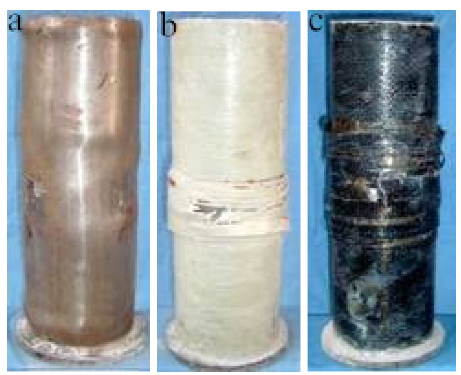
3.1. General Observations

The CFST specimen experienced continuous dilation in the mid-height region and localized outward buckling of the steel tube near the tube ends at large axial shortenings, as shown in Figure 2a. All FCCFST specimens failed by rupture of the FRP wrap in the mid-height region, as a result of the lateral expansion of the concrete. The typical failure modes are shown in Figure 2b,c. The volume expansion of concrete and the local buckling of the steel tube in FCCFST specimens was not as obvious as that of the CFST specimen.
Figure 2. Typical failure modes: (a) concrete-filled steel tube (CFST) specimen; (b) GFCFST specimens; (c) CFCFST specimens.
Polymers 06 01333 g002

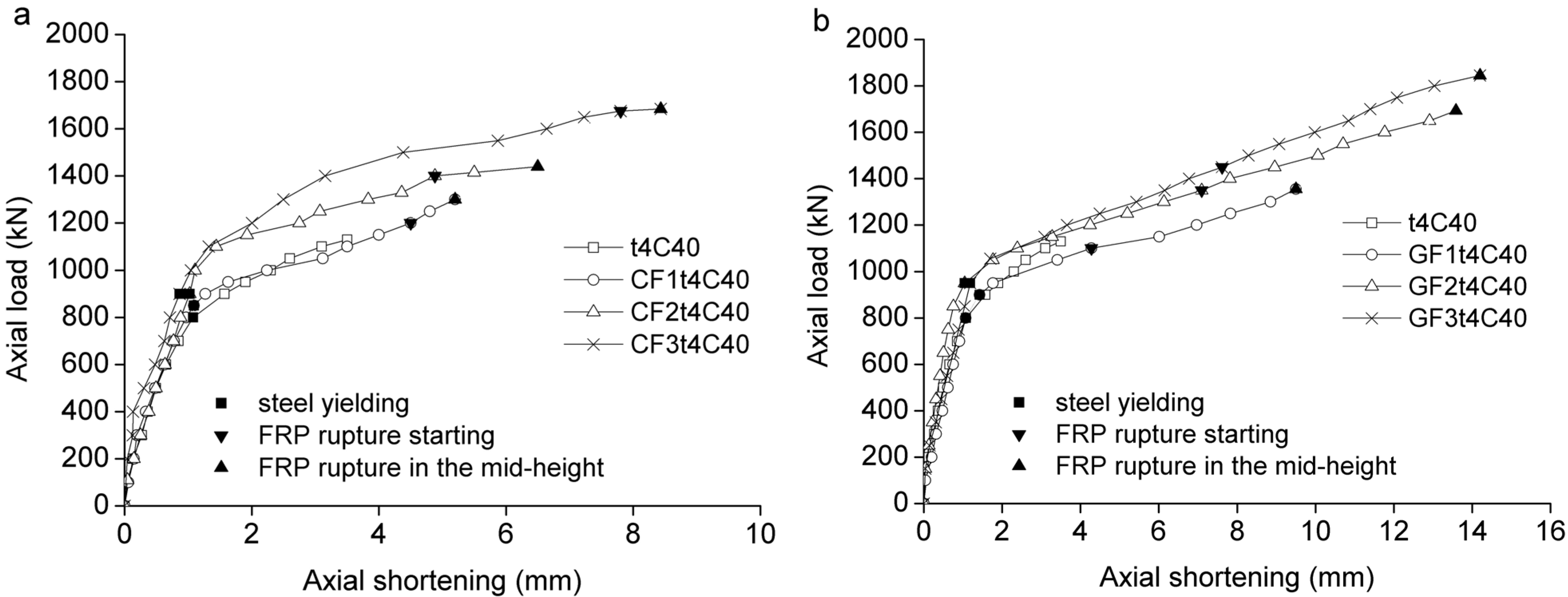
3.2. Axial Load-Axial Shortening Behavior

The axial load-axial shortening curves for the specimens are shown in Figure 3, Figure 5 and Figure 6, in which the axial shortening is the average value of the two LVDTs. The relationships between axial load and axial shortening up to the ultimate state of the specimens can be seen in these figures. For the FCCFST specimens, the ultimate state is defined as the state when the explosive rupture of the FRP wrap occurs at the mid-height region. The load at the ultimate state of the FCFST specimens is the same as their maximum load. The ultimate state for the CFST specimens is defined as the state when the load reaches their maximum load. The initial portion of axial load-axial shortening responses of a FCCFST specimen essentially followed the curve of the corresponding CFST specimen till a characteristic axial shortening was attained, which is the point when the axial load of specimen t4C40 increased up to about 75% of its ultimate load. After attaining the characteristic strain, the axial load-axial shortening relationships of FCCFST specimens show a higher modulus than those of the CFST specimen and eventually exhibited an almost linear behavior until the rupture of the FRP in the mid-height region happened. The experimental results for all specimens are shown in Table 2. Here, Ny is the axial load when the steel tube yielded; Nf is the axial load when the fracture of the FRP wrap was audible or visible; Nu and δu are the ultimate load and the axial shortening of the specimens at the ultimate state; εf is the maximum hoop strain of the FRP at the ultimate state. As expected, the additional FRP confinement led to enhancements in both load capacity and axial deformation capacity, and the degree of enhancement increased with the increasing of the FRP layer number for both CFCCFST and GFCCFST specimens.
Table 2. Test results for the columns.
SpecimensNy (kN)Nf (kN)εf (με)Nu (kN)δu (mm)kε2Nup (kN)Nu/Nup
t4C408001,1303.51,1011.03
CF1t4C408501,20010,2271,3005.20.761,2831.01
CF2t4C409001,40011,0251,4406.50.821,4660.98
CF3t4C409001,67010,8211,6859.40.811,6481.02
GF1t4C4090090019,8901,3559.50.771,3271.02
GF2t4C408501,35022,2881,69311.80.861,5541.09
GF3t4C409501,45024,2821,84513. 60.941,7801.04
CF2t3C408001,33010,8161,3307.10.811,2711.05
CF2t5C401,1501,55011,1041,6507.30.831,6311.01
CF2t4C509001,43010,1891,5488.30.761,5501.00
CF2t4C609501,6588,8531,6588.50.661,6021.03

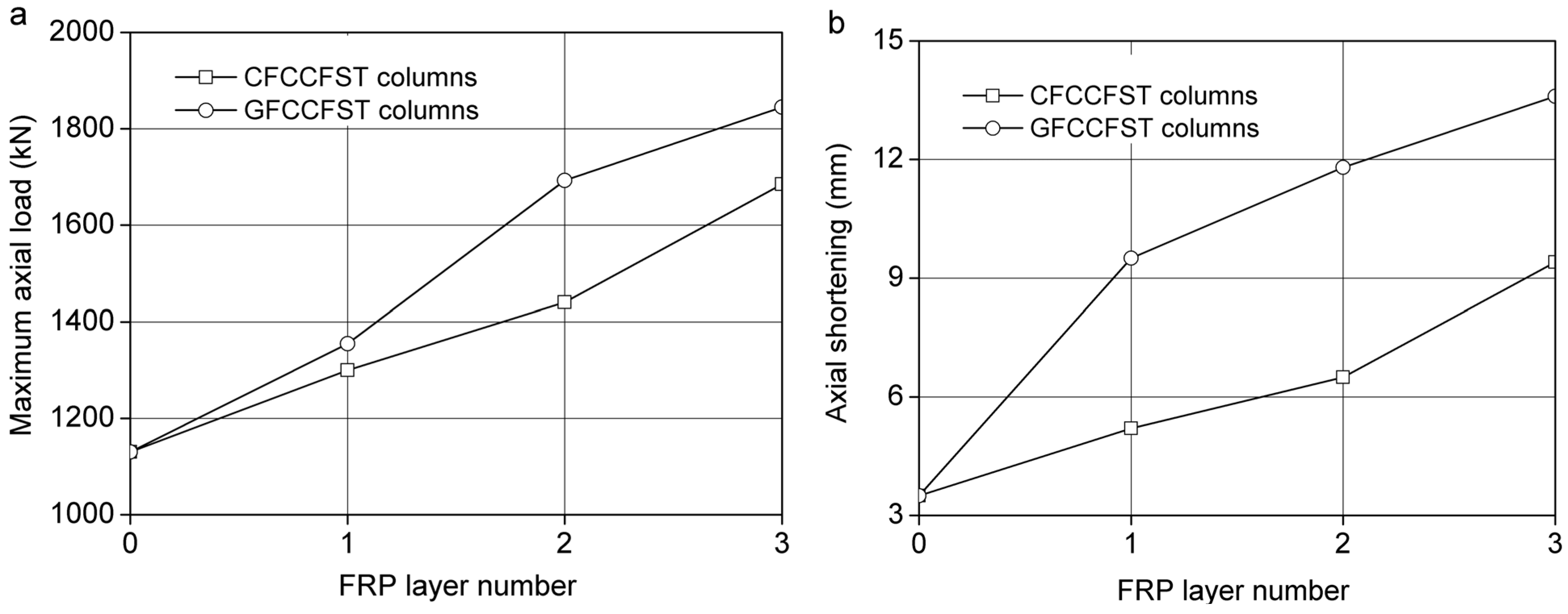
3.2.1. Effect of Fiber-Reinforced Polymer (FRP) Confinement

Figure 3 shows the comparison of axial behavior for the FCCFST specimens and the corresponding CFST specimens. The CFST specimen and the FCCFST specimens behaved similarly till the steel tube yielded. When the steel tube yielded, the axial load of the FCCFST specimens increased in an approximately linear way. This is because the FRP wrap provided confinement to the steel tube and the concrete when the steel tube yielded; thereafter, the decrease of the rigidity of the CFST columns was delayed.
The FCCFST specimens exhibited a higher yielding load, but a similar axial shortening with the yielding load. It also can be seen from Figure 3 that for the FCCFST specimens, when the FRP layer number increased, the axial shortening at Nf increased. It is worth noting that for the CFCCFST specimens, the axial shortening at Nf was close to that at Nu, but for the GFCCFST specimens, the axial shortening at Nf was much smaller than that at Nu. This accorded with the fact that the failure of CFCCFST specimens was much more abrupt than that of the GFCCFST specimens.
With the increasing of the FRP layer number, the ultimate loads and the corresponding axial shortening increased, as shown in Figure 4. With the additional CFRP confinement, the ultimate load and the axial shortening at the ultimate load was increased by 50% and 169%, respectively. When GFRP wrap was used, the ultimate load and the corresponding axial shortening was increased by 60% and 289%, respectively. By comparison, the GFCCFST specimens obtained more enhancements in ultimate load and axial deformation capacity than the CFCCFST specimens, particularly in terms of axial deformation capacity.
Figure 3. Axial load vs. axial shortening curves in terms of the FRP layer number: (a) CFCCFST specimens; (b) GFCCFST specimens.
Polymers 06 01333 g003
Figure 4. The effect of FRP confinement: (a) ultimate load; (b) axial shortening at the ultimate load.
Polymers 06 01333 g004

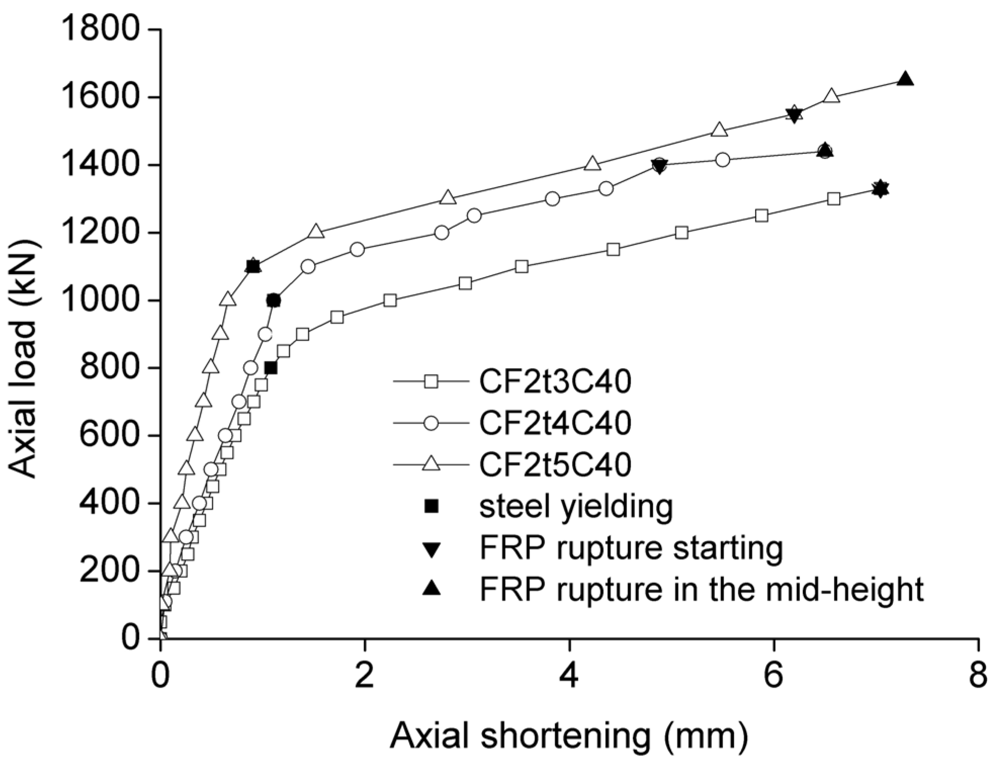
3.2.2. Effect of the Thickness of the Steel Tube

Figure 5 shows the effect of the thickness of the steel tube on the behavior of axially loaded FCCFST specimens. When the thickness of the steel tube increased, the ultimate load increased. However, increasing the thickness of the steel tube had no obvious effect on the axial shortening at the ultimate load. In the first ascending branch, the curve of the column with the thicker steel tube had a larger slope, indicating a higher rigidity. In the second ascending branch, the curves of the three columns were parallel to each other. This situation can be explained by the fact that after the yielding of the steel tube, the increase of the axial load is attributed to the confinement by the FRP wrap, which behaves in a linear elastic way. In this stage, the confinement provided by the FRP wrap dominates its behavior.
Figure 5. Axial load vs. axial shortening curves in terms of the thickness of the steel tube.
Polymers 06 01333 g005

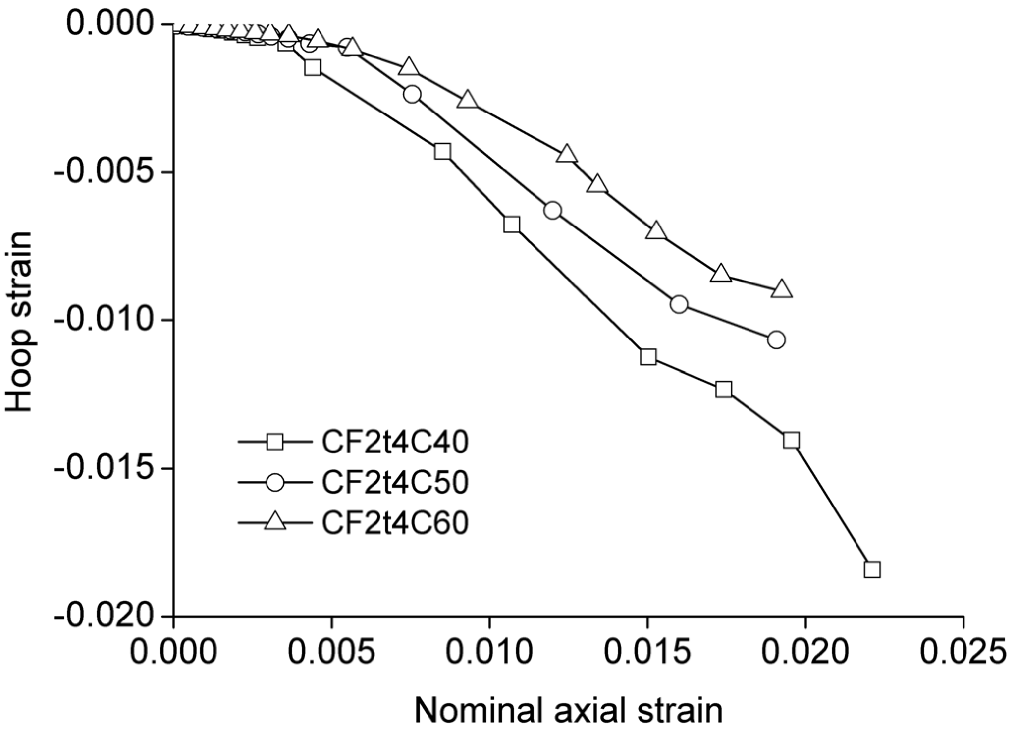
3.2.3. Effect of Concrete Strength

Figure 6 shows the effect of concrete strength on the compressive behavior of the FCCFST specimens. These three specimens exhibited similar behavior. When the concrete strength increased, the ultimate load and the axial shortening at the ultimate load increased slightly.
Figure 6. Axial load vs. axial shortening curves in terms of concrete strength.
Polymers 06 01333 g006

3.3. Behavior of Confined Concrete

Without considering the small axial stiffness of the FRP wrap, the axial load carried by the concrete core can be obtained by deducting the axial load carried by the steel tube from the measured ultimate load. The axial load carried by the steel tube is calculated by the product of the cross-sectional area (As) and the yield strength (fy) of the steel tube. Then, the axial stress of the confined concrete can be obtained by dividing the deduced axial load by the cross-section of the concrete core. On the basis of the previous definition of ultimate state, the axial strain of the columns is also the axial strain at the ultimate state of the confined concrete.
The values of the stress and the strain of the confined concrete at the ultimate load are summarized in Table 3, in which fccf is the concrete stress of an FCCFST specimen at the ultimate load; fcc is the concrete stress of a CFST specimen at the ultimate load; εccf is the axial strain at the ultimate load of an FCCFST specimen; and εcc is the axial strain at the ultimate load of a CFST specimen. The nominal axial strain of the specimens, obtained by dividing the axial shortening by the height of the columns, is used for interpreting the εccf and εcc of confined concrete. It is evident from Table 3 that both the stress and the axial strain at the ultimate state can be significantly enhanced as a result of FRP confinement.
Table 3. Stress and strain of the confined concrete at the ultimate load.
Specimensfcc, fccffcc/fccfεcc, εccfεccccf
t4C4065.800.0088
CF1t4C4080.831.230.01301.49
CF2t4C4093.221.420.01631.86
CF3t4C40114.891.750.02352.69
GF1t4C4085.701.300.02382.71
GF2t4C40115.601.760.02953.37
GF3t4C40129.051.960.03403.89

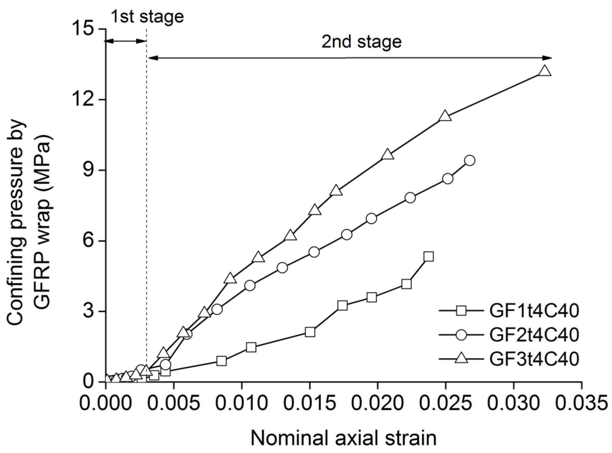
3.3.1. Confining Pressure

The confining pressure from the FRP wrap can be found from the hoop stress in the FRP wrap. Based on the force equilibrium condition, the confining pressure can be determined as:
Polymers 06 01333 i001
in which σf is the confining pressure provided by the FRP wrap; Ef is the elastic modulus of the FRP wrap; tf is the product of the nominal thickness of the single layer of the FRP wrap and the FRP layer number; ts is the thickness of the steel tube; εfa is the average hoop strain of the FRP wrap; and R is the internal diameter of the steel tube.
Figure 7 shows the development of the confining pressure during the loading for the GFCCFST specimens. It reveals that the development of the confining pressure from the FRP wrap can be divided into two stages. These two stages are distinguished by a characteristic strain, which is near to the ultimate strain of unconfined concrete. In the first stage, the confining pressure from the FRP wrap develops slowly. In this stage, the concrete does not dilate, and the confining pressure from the steel tube is near zero; however, the steel tube expands faster than the concrete core, because of its larger initial Poisson’s ratio. This expansion was constrained by the FRP wrap, promoting a hoop stress in the FRP wrap. In the second stage, the confining pressure from the GFRP wrap increased at a constant rate, due to the lateral dilation. In this stage, the concrete dilates faster than the steel tube, and it pushes the steel tube outward, resulting in a confinement pressure at the interfaces and hoop tensile stress in both the steel tube and the FRP wrap. The FRP wrap not only constrains the lateral displacement of the steel tube, but also provides additional confinement to concrete through the steel tube.
Figure 7. Confining pressure from the GFRP wrap.
Polymers 06 01333 g007

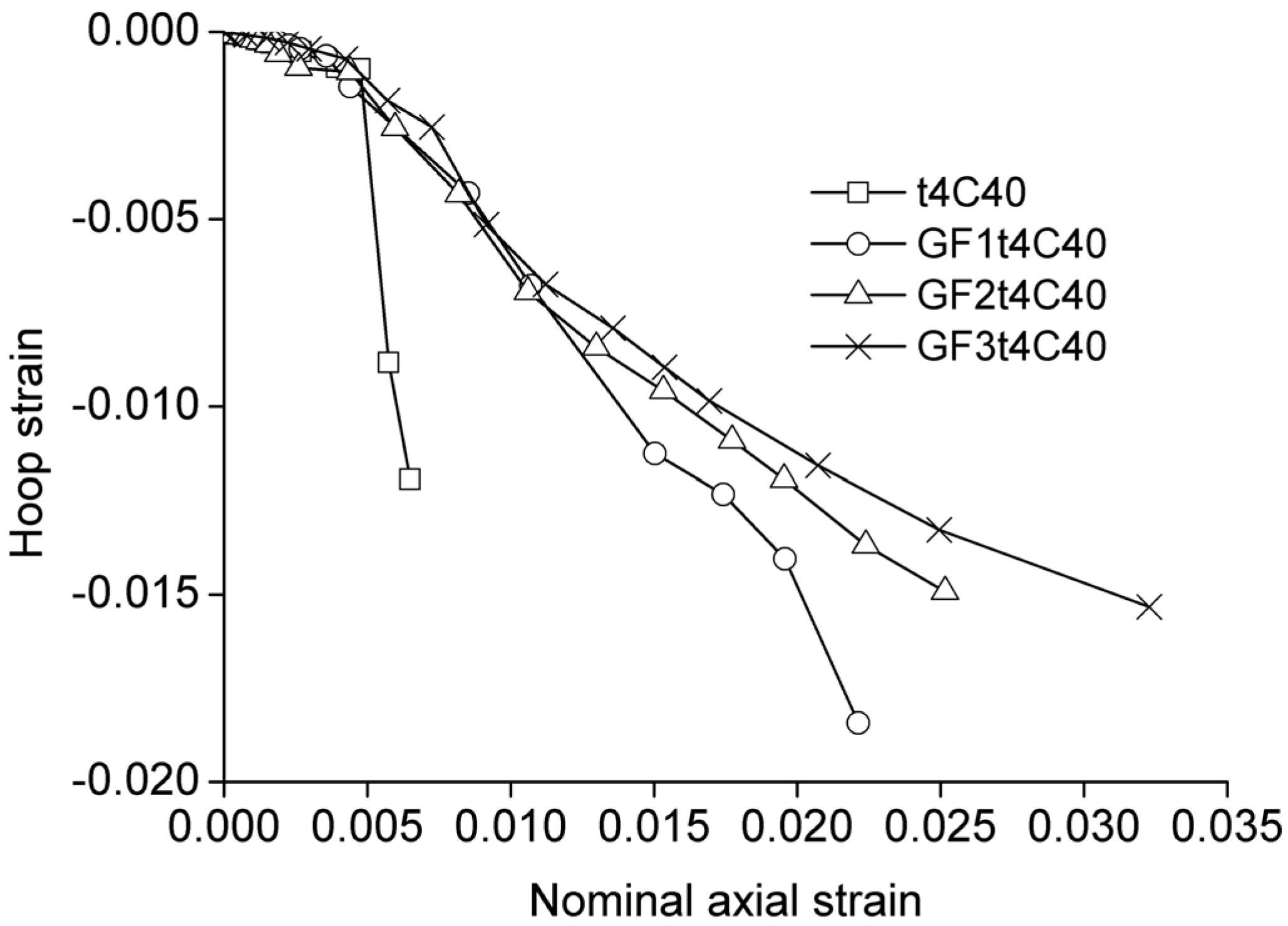
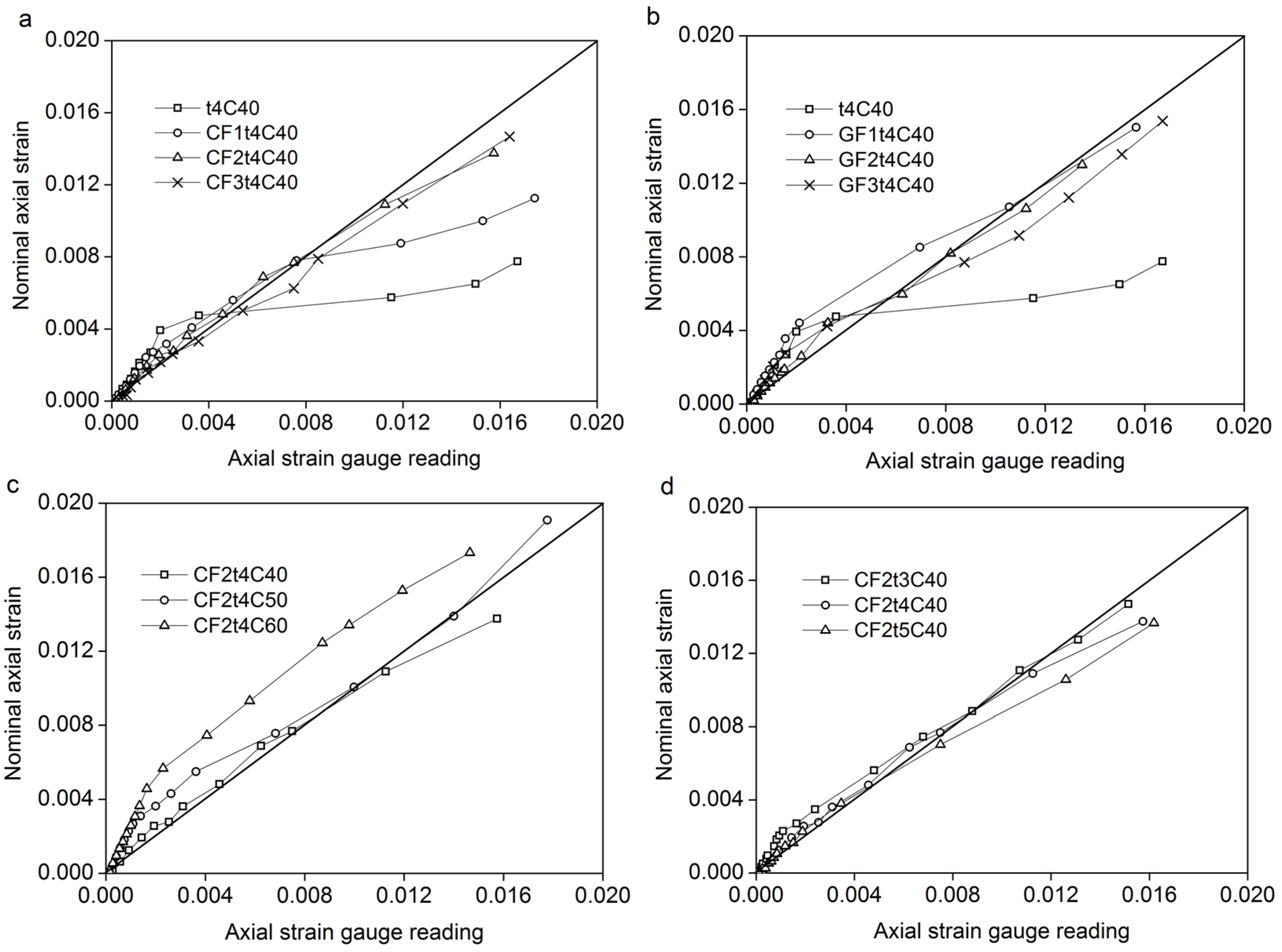
3.3.2. Lateral Expansion Behavior

The lateral-to-axial strain curves for the GFCCFST specimens are shown in Figure 8, in which the nominal axial strain is used, whereas the lateral strain is the average value of the four hoop strain gauges mounted to the steel tube. Figure 8 shows that the curves are generally higher for specimens with a thicker FRP wrap, indicating that at the same axial strain, the lateral expansion of the concrete was smaller when a thicker FRP was used.
Figure 8. Nominal axial strain vs. hoop strain in terms of FRP layer number.
Polymers 06 01333 g008
Figure 9 shows the lateral-to-axial strain curves of the FCCFST specimens with concrete of different strengths. The curves are generally higher for specimens with a higher concrete strength. This indicates that at the same axial strain, the lateral expansion of the concrete was smaller when the concrete with a higher strength was used. This is due to the decreased deformation capacity of the higher strength concrete. The specimens with higher strength concrete exhibited less hoop strain and axial strain at the ultimate load, indicating a lower deformation capacity.
Figure 9. Nominal axial strain vs. hoop strain in terms of concrete strength.
Polymers 06 01333 g009

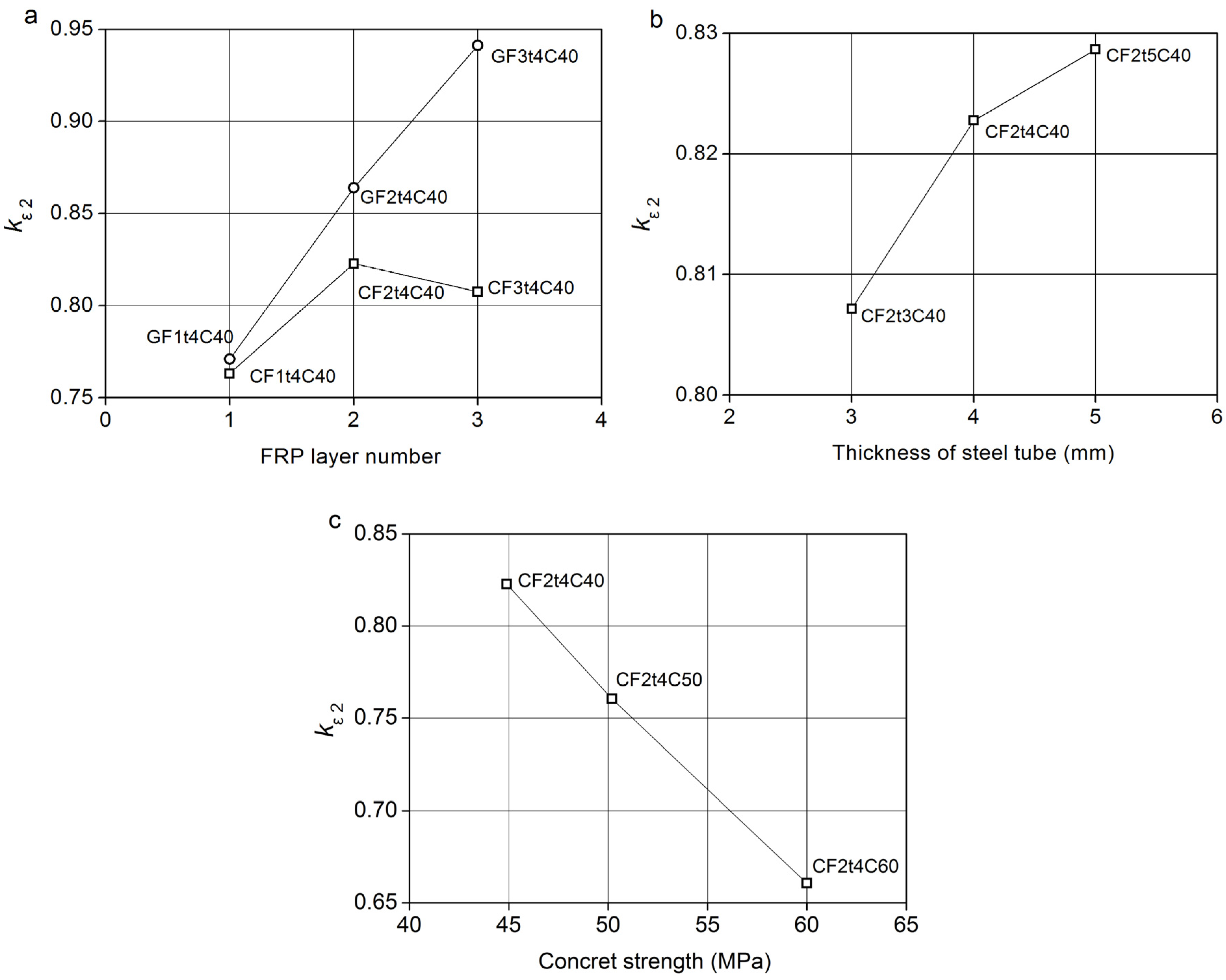
3.3.3. Strain Efficiency of FRP Wrap

The efficiency of FRP wrap is often evaluated by the so-called FRP efficiency factor, kε, which is defined as the ratio of the average FRP hoop rupture strain in a confined column to the ultimate tensile strain obtained from flat coupon tests [23]. The FRP efficiency factor, kε, depends on two factors, namely, the strain distribution in the FRP wrap and the maximum hoop strain in the FRP wrap at the ultimate state. The influence of the strain distribution is interpreted by the ratio of the average hoop strain to the maximum at the ultimate state (kε1). The factor, kε1, is defined to account for the effect of a non-uniform strain distribution in the FRP jacket, mainly due to the heterogeneity of the concrete and the possible eccentricity of loading. The influence of the maximum hoop strain can be interpreted in terms of the ratio of the maximum hoop strain, εf, to the ultimate tensile strain from flat coupon tests, εfu (kε2 = εffu).
Table 2 gives the values of kε2 obtained from the experimental results. The value of kε2 varied from 0.66 to 0.94 depending on the FRP layer number, the FRP type, the thickness of the steel tube and concrete strength. The effects of these parameters on kε2 are shown in Figure 10.
The effect of the FRP layer number on kε2 is shown in Figure 10a. The value of kε2 increased with the FRP layer number. GFRP efficiency is higher than the CFRP efficiency, in particular with two or three layers. The average value of kε2 for the GFRP wrap is 0.857, being similar to the average value of 0.820 for the GFRP-confined concrete column found by Lam and Teng [24]. The average value of kε2 for the CFRP wrap is 0.797, being larger than the average value of 0.707 for the GFRP-confined concrete column given in [24]. Increasing the thickness of the steel tube increased the value of kε2 slightly, as shown in Figure 10b. The effect of concrete strength on the value of kε2 is illustrated in Figure 10c. When the concrete strength increased, the value of kε2 decreased significantly. The reason is attributed to the fact that the concrete with higher strength had a decreased dilation capacity. The smaller lateral dilation of concrete promotes lower hoop stress in the steel tube and FRP wrap.
Based on the above analysis, the FRP efficiency mainly depends on the FRP type, the FRP layer number and the concrete strength.
Figure 10. The values of kε2: (a) the FRP layer number; (b) the thickness of the steel tube; (c) concrete strength.
Polymers 06 01333 g010

3.4. Local Behavior of Steel Tube

The CFST specimen experienced continuous dilation in the mid-height region in the later stage of loading. The local buckling of all FCCFST specimens was not so obvious, due to the external confinement from the FRP wrap. The comparisons between the nominal axial strain and the axial strain gauge reading are used to analyze the local behavior of the steel tube, as shown in Figure 11. The axial strain gauge readings shown in Figure 11 are averaged from the four axial strain gauges.
Figure 11 shows that for the CFST specimen, t4C0, the nominal axial strain and the average axial strain readings are generally in close agreement until an axial strain of 0.006, beyond which the average axial strain reading becomes significantly larger than the nominal axial strain. This indicates that local buckling deformation occurred in the mid-height region of the steel tube. For all the FCCFST specimens, except the specimen, CF1t4C40, the nominal axial strain and the average strain gauge readings were similar throughout the entire loading process, indicating that the local buckling of the steel tube was not significant in these specimens. This is consistent with the experimental observation. For the specimen, CF1t4C40, the average axial strain reading is in close agreement until an axial strain of 0.008.
Figure 11. Comparisons between nominal axial strain and axial strain gauge readings.
Polymers 06 01333 g011

4. Prediction of Load Capacity

The load capacity of the FCCFST (Nu) columns depends on the strength contributions of the steel tube (Ns) and the concrete core (Nc). The strength of the concrete is related to the unconfined concrete strength (Nc0), the strength enhancement due to the steel tube confinement (Ncs) and the strength enhancement due to the FRP confinement unconfined concrete (Ncf). Therefore, the Nu can be given as follows:
Nu = Ns + Nc0 + Ncs + Ncf
Without considering the mutual action of the steel tube and FRP wrap in improving the behavior of FCCFST columns, the value of the first three terms in Equation (2) can be obtained using the design method proposed for CFST columns by Han [25], as given by Equation (3):
Nu = Ac fc(1 + 1.8ξs)
where fc is the strength of unconfined concrete and ξs is the confinement index of the steel tube and expressed as:
Polymers 06 01333 i002
According to the previous research [26,27], the strength enhancement due to FRP confinement, Ncf, is closely related to the confining pressure from the FRP wrap, which is defined in Equation (1). The confining pressure from the FRP wrap mainly depends on the thickness of, the elastic modulus of and the average hoop strain in the FRP wrap and the diameter of the column. Yu [28] employed an FRP confinement index (ξf) to consider the effect of these parameters. According to Yu [28], the Ncf can be estimated by Equation (6):
Polymers 06 01333 i003
in which Af is the cross-sectional area of the FRP wrap:
Ncf = 1.15ξf fc Ac
Based on Equations (3) and (6), the load capacity of FCCFST columns can be predicted using the following equation:
Nu = (1 + 1.8ξs + 1.15ξf ) fc Ac
The predicted ultimate loads using Equation (7) are compared with the experimental results obtained in this paper. The predictions agree well with the experimental results. The comparisons are shown in Table 2. A mean ratio (Nu/Nup) of 1.025 with a standard deviation of 0.026 is obtained.
Equation (7) is also used to analyze the test results reported by Xiao et al. [6], Tao et al. [9], Hu et al. [7] and Gu et al. [29]. The comparisons are shown in Table 4. As can be seen, Equation (7) can be used to accurately predict the ultimate strength of the specimens from Tao et al. [9], Hu et al. [7] and Gu et al. [29], but overestimates the ultimate strength of the specimens from Xiao et al. [6]. The reason may be attributed to the fact that these specimens have relative high ξf. Thus, more research on the FCFST columns with strong confinement needs to be carried out.
Table 4. Comparisons of the predicted and experimental ultimate strengths.
SpecimensD (mm)ts (mm)fy (MPa)fcu (MPa)fc (MPa)nftfff (MPa)ξsξfNu (kN)Nup (kN)Nu/Nup
Xiao et al. [6]
CFT1522.953564700.69145315930.91
CCFT-2L-11522.953564722.88970.691.69223329720.75
CCFT-2L-21522.953564722.88970.691.69226629720.76
CCFT-4L-11522.953564745.68970.693.38343943510.79
CCFT-4L-21522.953564745.68970.693.38343943510.79
Tao et al. [9]
C1-01563.023046042120.45124513280.94
C1-11563.02304610.17042120.450.48164917310.95
C1-21563.02304620.34042120.450.96205321350.96
C2-02503.023046042120.28283128980.98
C2-12503.02304610.17042120.280.29347835450.98
C2-22503.02304620.34042120.280.58412641910.98
Hu et al. [7]
F0-10220422264200.1718260.240.00186417031.09
F1-10220422264210.1718260.240.17199319321.03
F2-10220422264220.1718260.240.34212721600.98
F3-10220422264230.1718260.240.50242723891.02
F0-1352031.52424200.1718260.190.00169916001.06
F2-1352031.52424220.1718260.190.33201420550.98
F3-1352031.52424230.1718260.190.50224422830.98
F4-1352031.52424240.1718260.190.67256125111.02
F0-20220212313600.1718260.140.00138012801.08
Hu et al. [7]
F2-20220212313620.1718260.140.39174917331.01
F3-20220212313630.1718260.140.58196119591.00
F4-20220212313640.1718260.140.77226521851.04
Gu et al [29]
0-1.51271.53505500.398909030.99
0-2.51292.53505500.65114011570.99
0-3.51313.53105500.82129313130.98
0-4.51334.53105501.06152815440.99
1-1.51271.53505510.16712600.390.16108610001.09
1-2.51292.53505510.16712600.650.16129412551.03
1-3.51313.53105510.16712600.820.16134814130.95
1-4.51334.53105510.16712601.060.17168916451.03
2-1.51271.53505520.33412600.390.32128310961.17
2-2.51292.53505520.33412600.650.32150613531.11
2-3.51313.53105520.33412600.820.33159315121.05
2-4.51334.53105520.33412601.060.33184617461.06

5. Conclusions

This paper presents an experimental study aimed at gaining a further understanding of the compressive behavior of FRP-confined concrete-filled steel tube columns. The external FRP wrap is provided to constrain outward local buckling deformation of the steel tube and to better confine the concrete core. The examined parameters were the FRP layer number, the thickness of the steel tube and the concrete strength. On the basis of experimental results, the following conclusions can be drawn:
  • The load capacity and the axial deformation capacity of concrete-filled steel tube columns can be effectively improved by the FRP wrap. All specimens failed by the explosive rupture of the FRP in the mid-height region because of the lateral expansion of the concrete.
  • The FRP wrap can delay the outward local buckling deformation of the steel tube and suppress the lateral expansion of the concrete in the CFST column. The strength and the strain capacity of the concrete can be enhanced by the additional confinement from the FRP wrap.
  • The GFRP wrap has higher strain efficiency than the CFRP wrap. The CFRP efficiency increases with the increasing of the CFRP layer number, but decreases with the increasing of the concrete strength.
  • A simple model is proposed to predict the load capacity of the FCCFST columns. The model can accurately predict the load capacity of the FCCFST columns with not too strong FRP confinement. However, it overestimates that of the FCCFST columns with strong FRP confinement. Therefore, there is further research needed to develop a more accurate design approach when strong FRP confinement is exerted on CFST columns.
The current phase of the study was focused on the experimental study of the load capacity of short FCCFST columns. Experimental and analytical investigation is under way to examine different details for the additional confinement, particularly for slender FCCFST columns and FCCFST columns subjected to eccentric loads.

Acknowledgments

The funding for this investigation was provided by the Young Scientist Project of the Natural Science Foundation of China (51108355), the Natural Science Foundation of Hubei Province, China (No. 2011CDB269), and the Fundamental Research Funds for the Central Universities, China. The authors greatly appreciate their financial support.

Author Contributions

The work presented here was carried out in collaboration between all authors. Yiyan Lu, Na Li and Shan Li defined the research theme. Na Li and Shan Li designed the research methods and tested the specimens. Na Li analyzed the data and wrote the paper. Shan Li co-worked on the data collection and their interpretation and presentation.

Conflicts of Interest

The authors declare no conflict of interest.

References

  1. Fam, A.; Qie, F.; Rizkalla, S. Concrete-filled steel tubes subjected to axial compression and lateral cyclic loads. J. Struct. Eng. 2004, 130, 631–640. [Google Scholar] [CrossRef]
  2. O’Shea, M.D.; Bridge, R.Q. Design of circular thin-walled concrete-filled steel tubes. J. Struct. Eng. 2000, 126, 1295–1303. [Google Scholar] [CrossRef]
  3. Xiao, Y. Applications of FRP Composites in Concrete Columns. Adv. Struct. Eng. 2004, 7, 335–343. [Google Scholar] [CrossRef]
  4. Teng, J.G.; Yu, T.; Ferando, D. Strengthening of steel structures with fiber-reinforced polymer composites. J. Constr. Steel Res. 2012, 78, 131–143. [Google Scholar] [CrossRef]
  5. Smith, S.T.; Kim, M.S.J.; Zhang, H.W. Behavior and Effectiveness of FRP Wrap in the Confinement of Large Concrete Cylinders. J. Compos. Constr. 2010, 14, 573–582. [Google Scholar] [CrossRef]
  6. Xiao, Y.; He, W.H.; Choi, K.K. Confined concrete-filled tubular columns. J. Struct. Eng. 2005, 131, 488–497. [Google Scholar] [CrossRef]
  7. Hu, Y.M.; Yu, T.; Teng, J.G. FRP-Confined Circular Concrete-Filled Thin Steel Tubes under Axial Compression. J. Compos. Constr. 2011, 15, 850–860. [Google Scholar] [CrossRef]
  8. Sundarraja, M.C.; Prabhu, G.G. Experimental study on CFST members strengthened by CFRP composites under compression. J. Constr. Steel Res. 2012, 72, 75–83. [Google Scholar] [CrossRef]
  9. Tao, Z.; Han, L.H.; Zhuang, J.P. Axial Loading Behavior of CFRP Strengthened Concrete-Filled Steel Tubular Stub Columns. Adv. Struct. Eng. 2007, 10, 37–46. [Google Scholar] [CrossRef]
  10. Dong, J.F.; Wang, Q.Y.; Guan, Z.W. Structural behaviour of recycled aggregate concrete-filled steel tube columns strengthened by CFRP. Eng. Struct. 2013, 48, 532–542. [Google Scholar] [CrossRef]
  11. Choi, K.K.; Xiao, Y. Analytical model of circular CFRP confined concrete-filled steel tubular columns under axial compression. J. Compos. Constr. 2010, 14, 125–133. [Google Scholar] [CrossRef]
  12. Liu, L.; Lu, Y.Y. Axial bearing capacity of short FRP confined concrete-filled steel tubular columns. J. Wuhan Univ. Technol. Mater. Sci. Ed. 2010, 25, 454–458. [Google Scholar] [CrossRef]
  13. Teng, J.G.; Hu, Y.M. Stress-strain model for concrete in FRP-confined steel tubular columns. Eng. Struct. 2013, 49, 156–167. [Google Scholar] [CrossRef]
  14. Li, S.Q.; Chen, J.F.; Bisby, L.A. Strain efficiency of FRP jackets in FRP-confined concrete-filled circular steel tubes. Int. J. Struct. Stab. Dy. 2012, 12, 75–94. [Google Scholar] [CrossRef]
  15. Yu, T; Hu, Y.M.; Teng, J.G. FRP-confined circular concrete-filled steel tubular columns under cyclic axial compression. J. Constr. Steel Res. 2014, 94, 33–48. [Google Scholar] [CrossRef]
  16. Che, Y.; Wang, Q.L.; Shao, Y.B. Experimental study on hysteretic behaviors of concrete-filled circular CFRP-steel tubular beam-columns. China Civ. Eng. J. 2011, 44, 46–54. (In Chinese) [Google Scholar]
  17. Mao, X.Y.; Xiao, Y. Seismic behavior of confined square CFT columns. Eng. Struct. 2006, 28, 1378–1386. [Google Scholar] [CrossRef]
  18. Li, S.; Lu, Y.Y.; Li, N. Experimental study on shear resistance performance of concrete-filled circular FRP-steel tube columns. J. Build. Struct. 2012, 33, 107–114. [Google Scholar]
  19. Shan, J.H.; Chen, R.; Zhang, W.X. Behavior of Concrete-Filled Tubes and Confined Concrete-Filled Tubes under High Speed Impact. Adv. Struct. Eng. 2007, 10, 209–218. [Google Scholar] [CrossRef]
  20. Xiao, Y.; Shen, Y.L. Impact Behaviors of CFT and CFRP-confined CFT Stub Columns. J. Compos. Constr. 2012, 16, 662–670. [Google Scholar] [CrossRef]
  21. Tao, Z.; Han, L.H.; Wang, L.L. Compressive and flexural behaviour of CFRP-repaired concrete-filled steel tubes after exposure to fire. J. Constr. Steel Res. 2007, 63, 1116–1126. [Google Scholar] [CrossRef]
  22. Standard Test Method for Tensile Properties of Polymer Matrix Composite Material; ASTM D3039/D3039M-08; American Society for Testing and Materials (ASTM): West Conshohocken, PA, USA, 2006.
  23. Pessiki, S.; Harries, K.; Kestner, J. Axial Behavior of Reinforced Concrete Columns Confined with FRP Jackets. J. Compos. Constr. 2001, 5, 237–245. [Google Scholar] [CrossRef]
  24. Lam, L.; Teng, J.G. Ultimate Condition of Fiber Reinforced Polymer-Confined Concrete. J. Compos. Constr. 2004, 8, 539–548. [Google Scholar] [CrossRef]
  25. Han, L.H. Theoretical analysis and experimental researches for the behaviors high strength concrete-filled steel tubes. Ind. Constr. 1997, 27, 39–44. (In Chinese) [Google Scholar]
  26. Lam, L.; Teng, J.G. Strength Models for Fiber-Reinforced Plastic-Confined Concrete. J. Struct. Eng. 2002, 128, 612–623. [Google Scholar] [CrossRef]
  27. Samaan, M.; Mirmiran, A.; Shahawy, M. Model of Concrete Confined by Fiber Composites. J. Struct. Eng. 1998, 124, 1025–1031. [Google Scholar] [CrossRef]
  28. Yu, Q. Behaviors of FRP-Confined Concrete Columns. Master’s Degree, Harbin Institute of Technology, Harbin, China, 2002. [Google Scholar]
  29. Gu, W., Guan; Zhao, Y.H.; Cao, H. Experimental study on concentrically-compressed circular concrete filled CFRP steel composite tubular short columns. J. Shenyang Archit. Civ. Eng. Univ. (Nat. Sci.) 2004, 20, 118–120. (In Chinese) [Google Scholar]

