The Effects of Loading Rate and Duration on the Axial Behavior of Low-Strength and Medium-Strength Noncircular Concrete Members Confined by Fiber-Reinforced Polymer Sheets


Abstract
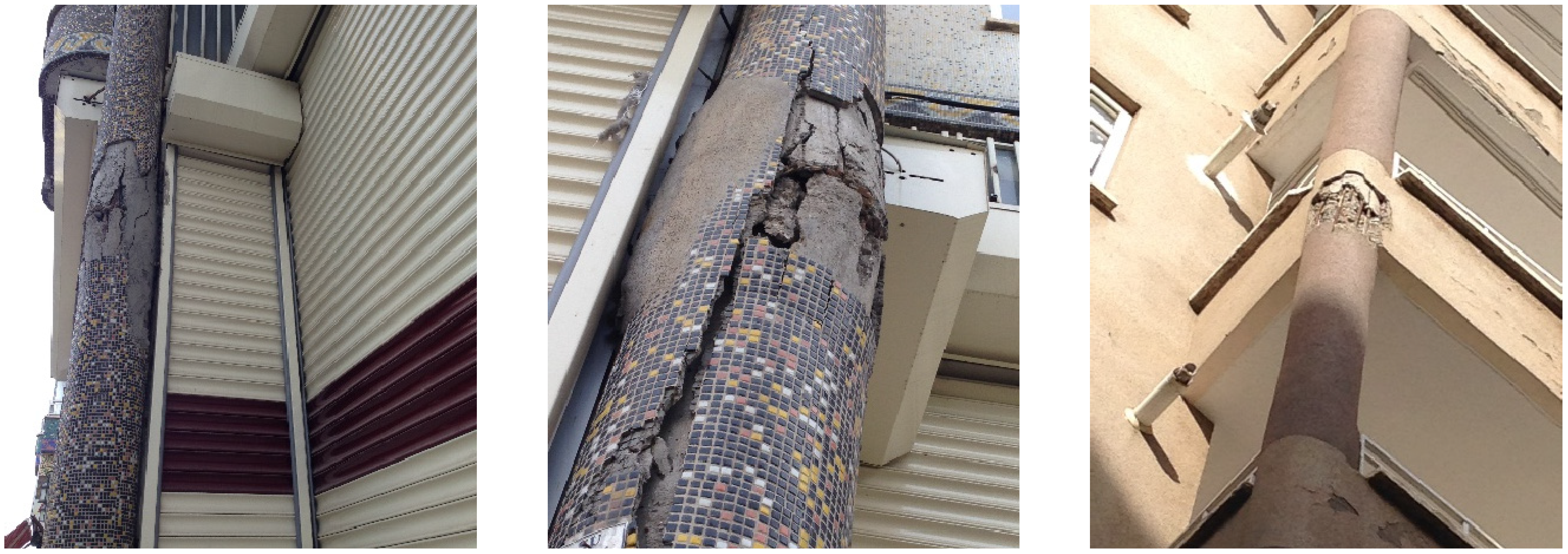
:1. Introduction

2. Experimental Program
2.1. Specimen Preparation


| Concrete Strength | Test Type | Specimens | Loading Rate (strain/min) | Sustained Load Duration (h) | Sustained Axial Stress Level 1 |
|---|---|---|---|---|---|
| Low Strength | Loading Rate | LM0L2A, LM0L2B | 0.002 | – | – |
| LM3L0A, LM3L0B | 0.04 | – | – | ||
| LM3L1A, LM3L1B | 0.02 | – | – | ||
| LM3L2A, LM3L2B | 0.002 | – | – | ||
| LM3L3A, LM3L3B | 0.0002 | – | – | ||
| Short-term Creep | LSRA, LSRB | – | 48, – | 3.37 f'co (0.90 f'cc) | |
| LSRC, LSRD | – | 48, – | 3.13 f'co (0.83 f'cc) | ||
| LSRE, LSRF | – | 96, 96 | 2.76 f'co (0.73 f'cc) | ||
| LSRI (unconfined) | – | 48 | 0.85 f'co | ||
| Medium Strength | Loading Rate | MM0L2A, MM0L2B, MM0L2C | 0.002 | – | – |
| MM3L0A, MM3L0B | 0.04 | – | – | ||
| MM3L1A, MM3L1B | 0.02 | – | – | ||
| MM3L2A, MM3L2B | 0.002 | – | – | ||
| MM3L3A, MM3L3B | 0.0002 | – | – | ||
| Short-term Creep | MSRA, MSRB, MSRH | – | 48, 48, 96 | 0.89 f'co (0.69 f'cc) | |
| MSRI | – | 96 | 1.00 f'co (0.77 f'cc) | ||
| MSRD, MSRE | – | 48, 96 | 1.11 f'co (0.86 f'cc) | ||
| MSRC, MSRF | – | 48, 96 | 1.20 f'co (0.92 f'cc) |
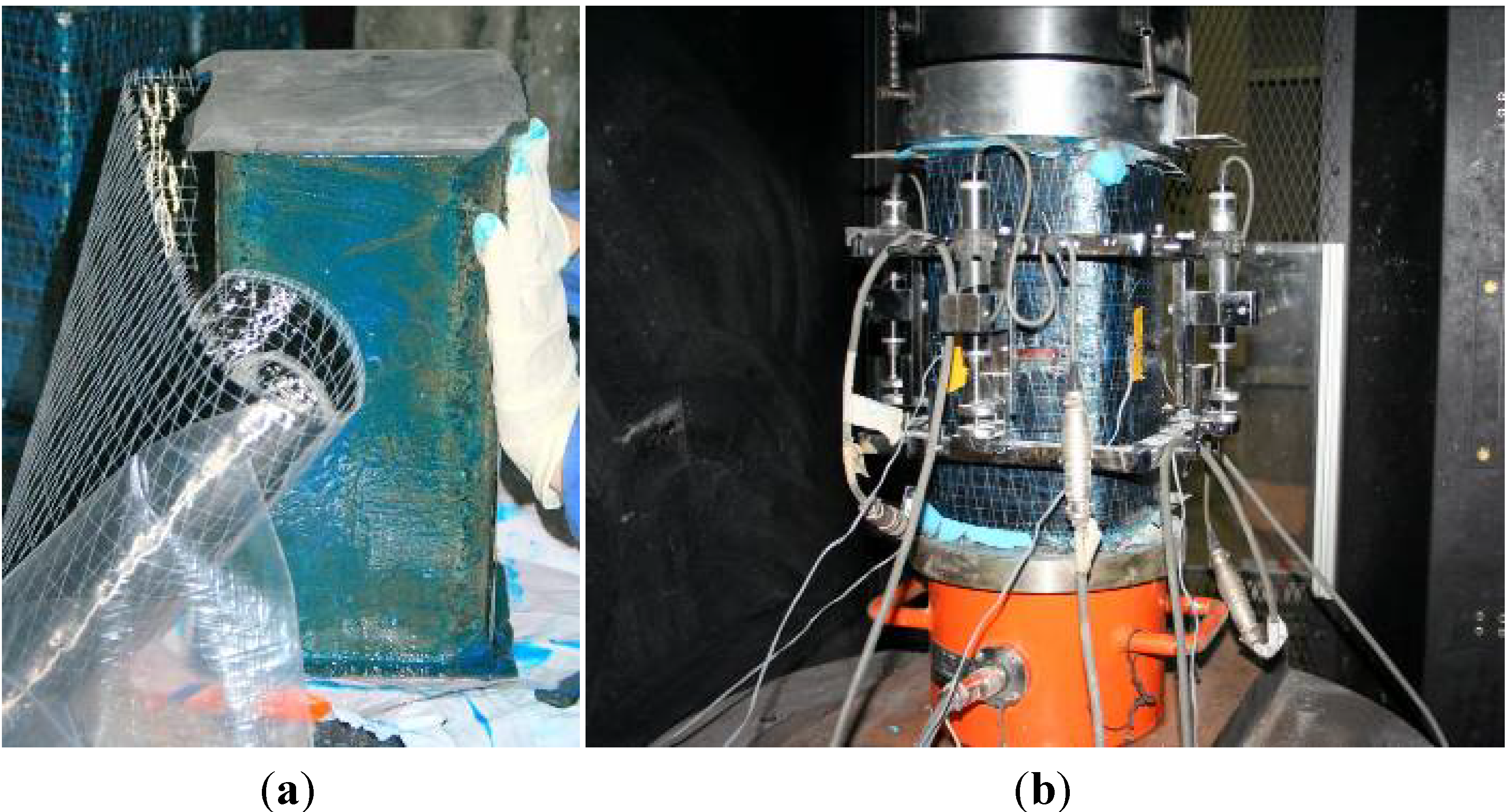
2.2. Test Setup
2.3. Short-Term Monotonic Tests
2.4. Short-Term Creep Tests
2.5. Residual Strength Tests
3. Results and Discussions
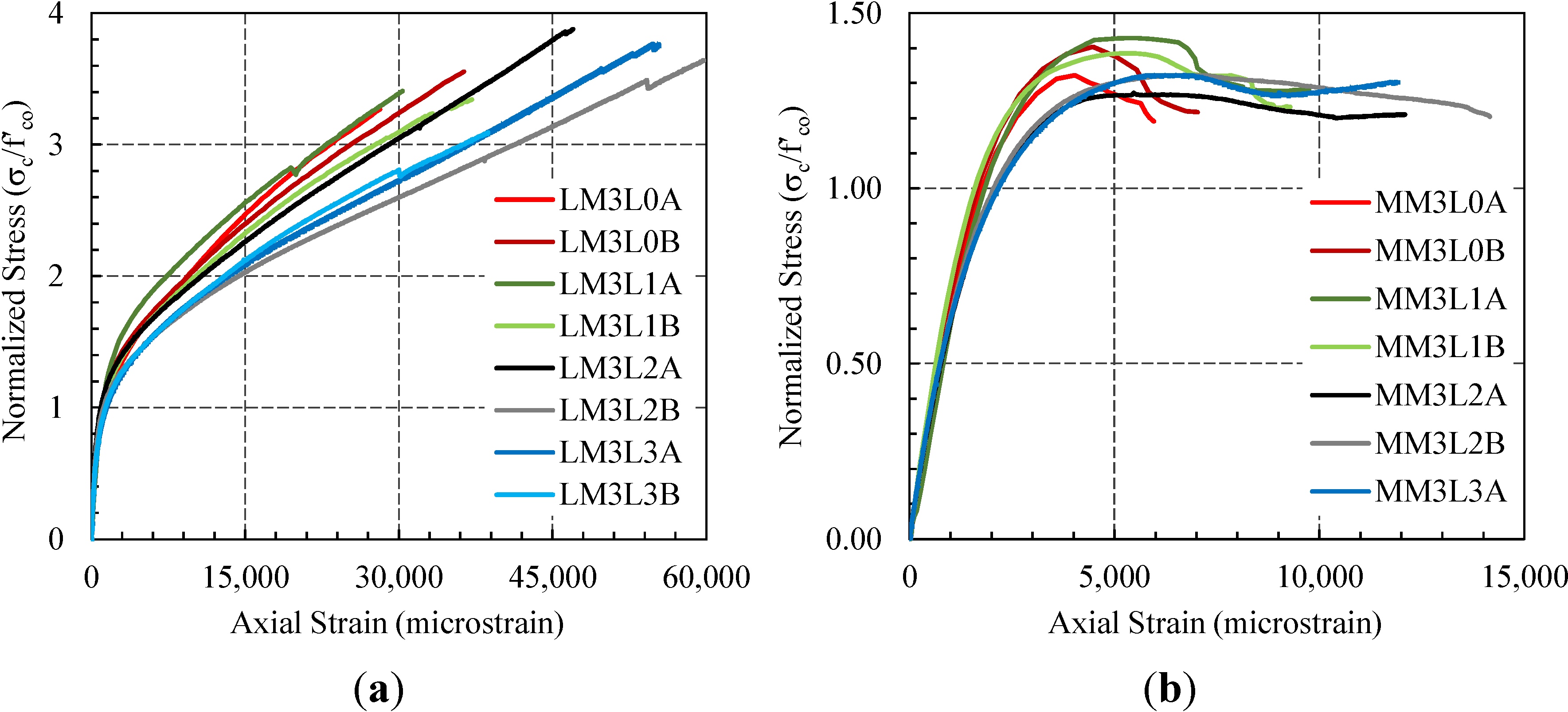
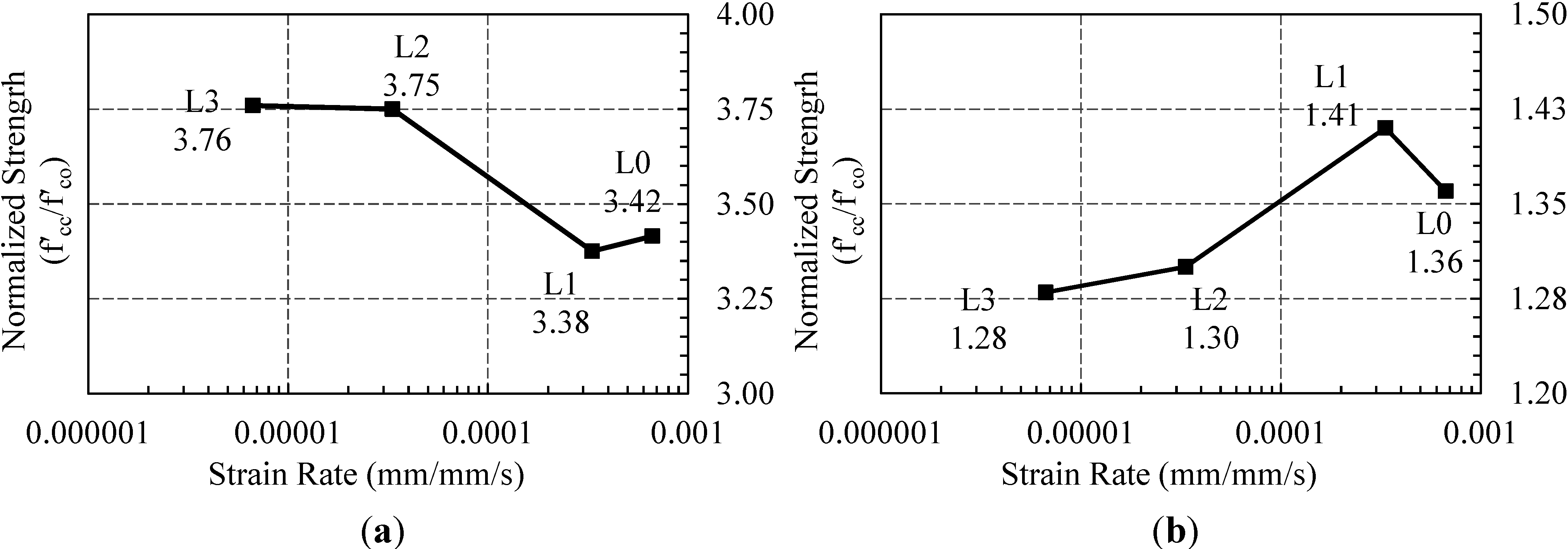
3.1. Short-Term Monotonic Tests


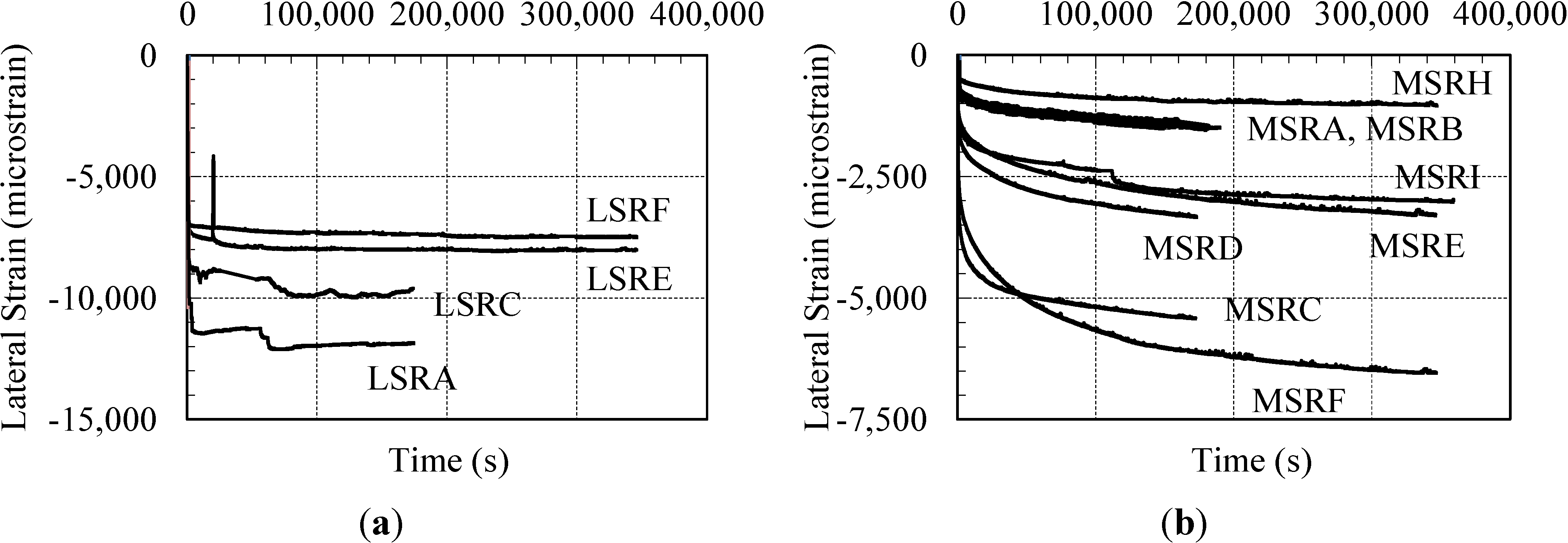
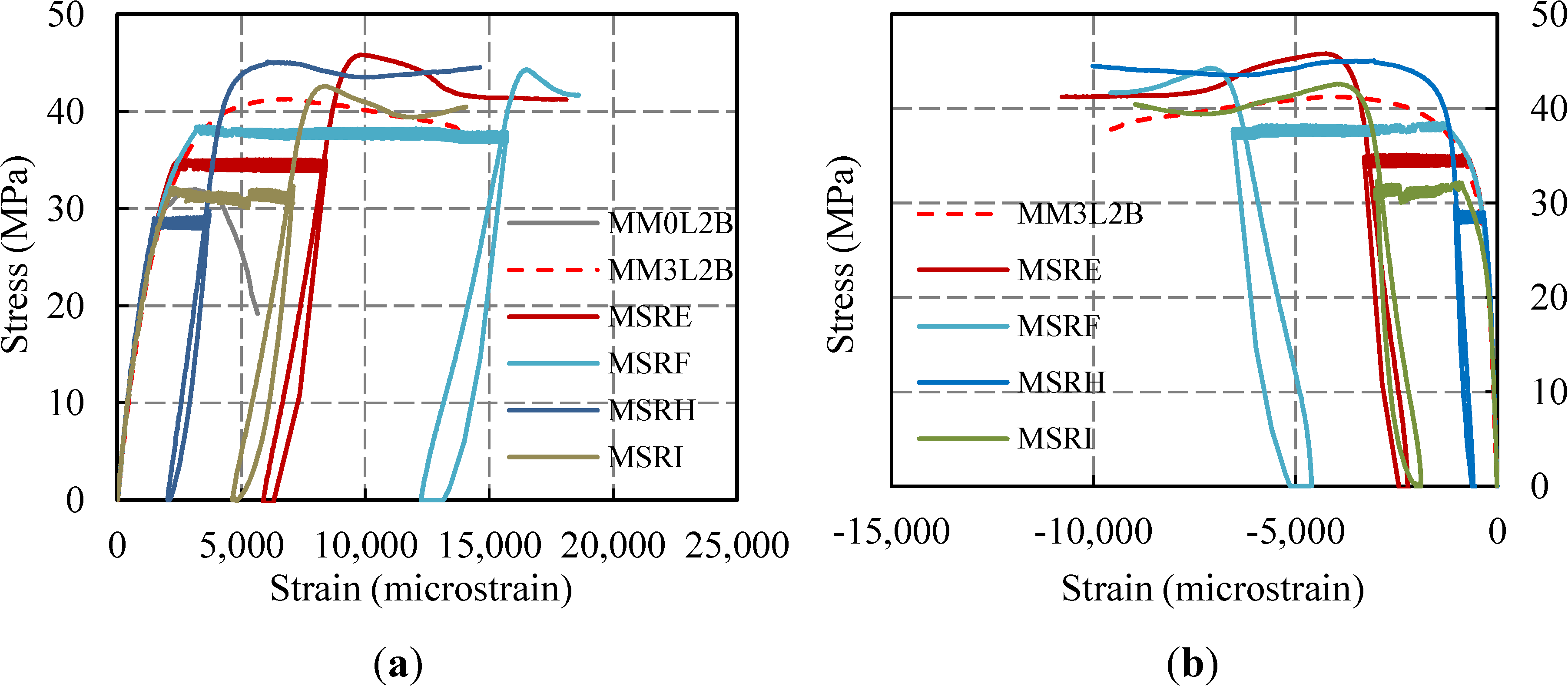
3.2. Short-Term Creep Tests

| Concrete Strength | Specimens | Sustained Load Duration (h) | Sustained Axial Stress Level | Failure During Sustained Loading | Likely to Fail in Practical Duration |
|---|---|---|---|---|---|
| Low | LSRA, LSRB | 48, – | 3.37 f'co (0.90 f'cc) | No, Yes | Yes |
| LSRC, LSRD | 48, – | 3.13 f'co (0.83 f'cc) | No, Yes | Yes | |
| LSRE, LSRF | 96, 96 | 2.76 f'co (0.73 f'cc) | No, No | No | |
| LSRI (no confinement) | 48 | 0.85 f'co | Yes | Yes | |
| Medium | MSRA, MSRB, MSRH | 48, 48, 96 | 0.89 f'co (0.69 f'cc) | No, No, No | No |
| MSRI | 96 | 1.00 f'co (0.77 f'cc) | No | Yes | |
| MSRD, MSRE | 48, 96 | 1.11 f'co (0.86 f'cc) | No, No | Yes | |
| MSRC, MSRF | 48, 96 | 1.20 f'co (0.92 f'cc) | No, No | Yes |
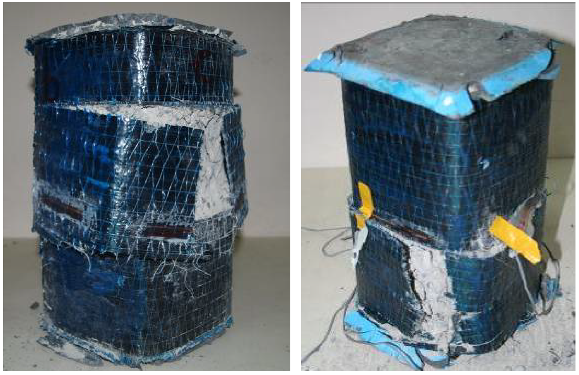
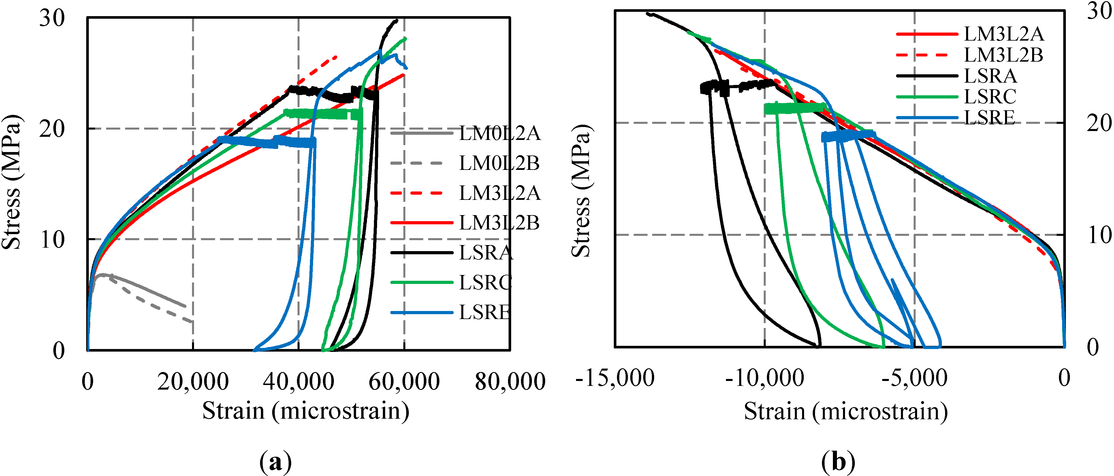
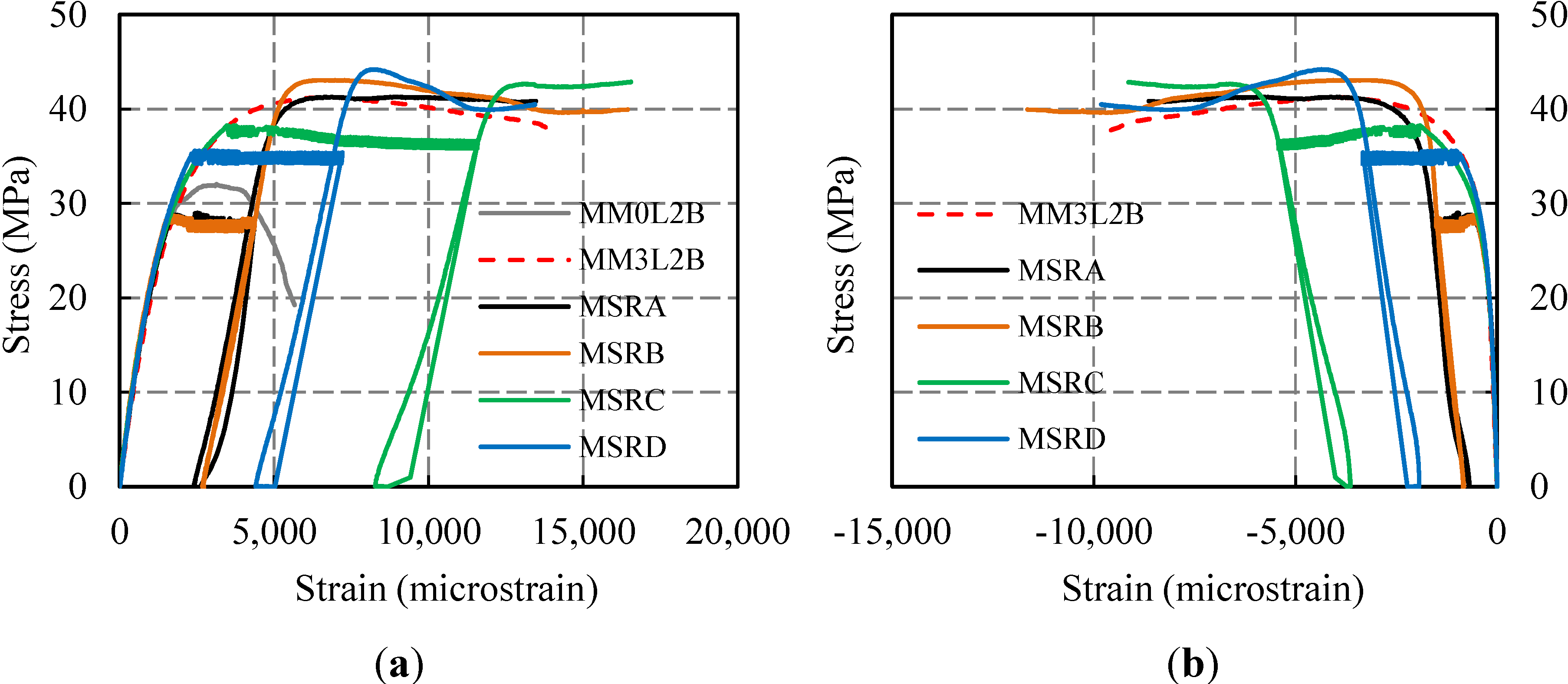
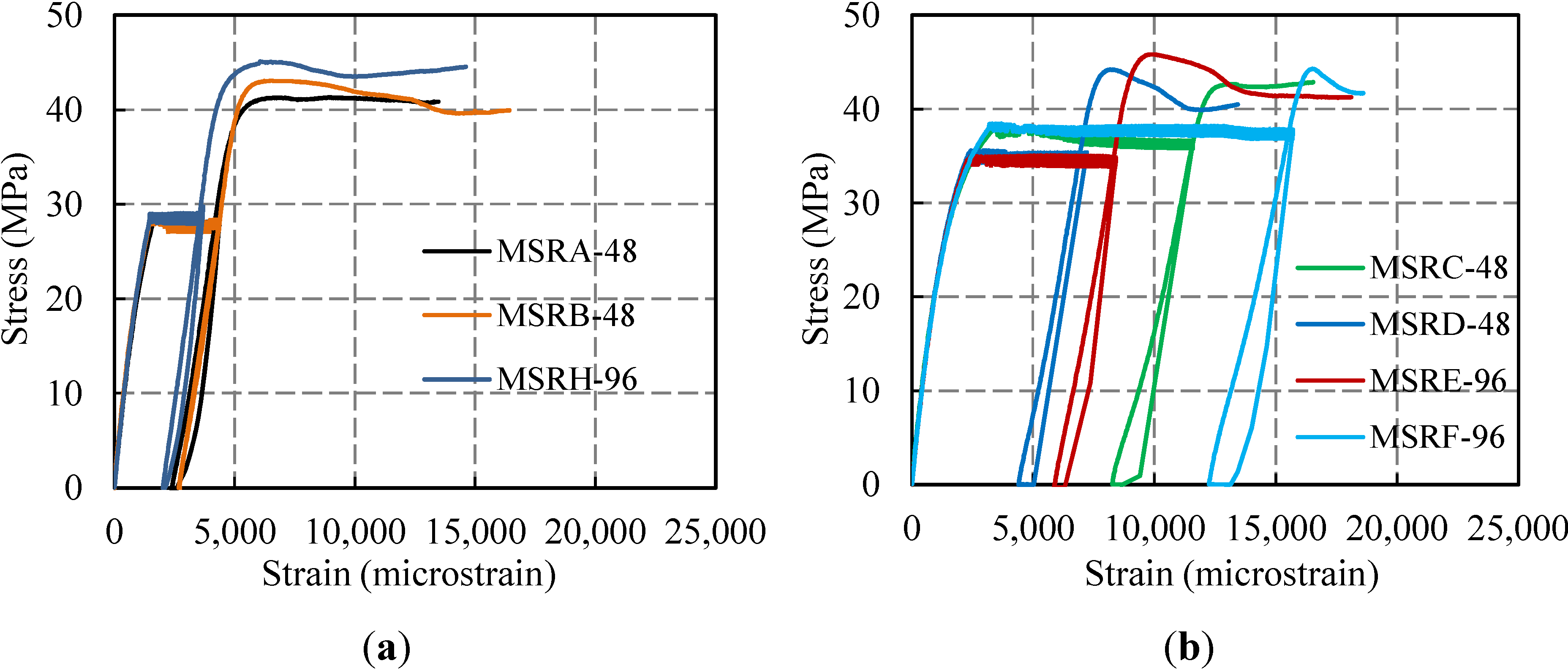
3.3. Residual Capacity Tests


| Concrete Strength | Specimens | Sustained Load Duration (h) | Sustained Axial Stress Level | Ultimate Strain Capacity (microstrain) | Residual Strain Capacity (microstrain) |
|---|---|---|---|---|---|
| Low | LSRA | 48 | 3.37 f'co (0.90 f'cc) | 58,500 | 12,300 |
| LSRC | 48 | 3.13 f'co (0.83 f'cc) | 60,100 | 15,100 | |
| LSRE, LSRF | 96, 96 | 2.76 f'co (0.73 f'cc) | 60,300, 55,200 | 28,300, 20,800 | |
| Medium | MSRA, MSRB, MSRH | 48, 48, 96 | 0.89 f'co (0.69 f'cc) | 13,400, 16,400, 14,600 | 10,900, 13,700, 12,400 |
| MSRI | 96 | 1.00 f'co (0.77 f'cc) | 14,000 | 9,410 | |
| MSRD, MSRE | 48, 96 | 1.11 f'co (0.86 f'cc) | 13,400, 18,100 | 8,900, 12,200 | |
| MSRC, MSRF | 48, 96 | 1.20 f'co (0.92 f'cc) | 16,500, 18,500 | 8,200, 6,300 |
4. Conclusions
- The stress-strain behavior of CFRP-confined concrete is affected by the change in the loading rate.
- As also observed for cylindrical specimens, the strength of CFRP-confined medium-strength concrete prisms increases with the increasing strain rate (about an 11% difference between low and high strain rates). However, retrofitted, low-strength concrete specimens tend to have less strength enhancement with the increasing strain rate (about an 8% difference between low and high strain rates).
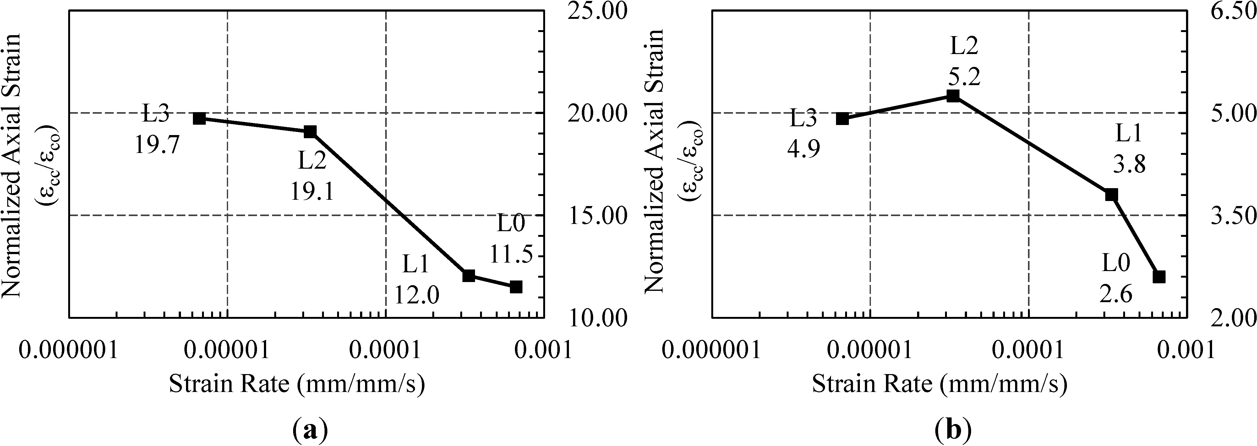
- Both low- and medium-strength concrete specimens exhibit higher strain capacities in the case of lower strain rates. The axial strain capacities at the lowest rate are approximately 70% and 90% higher than the strain capacities at the highest rate, for low- and medium-strength specimens, respectively.
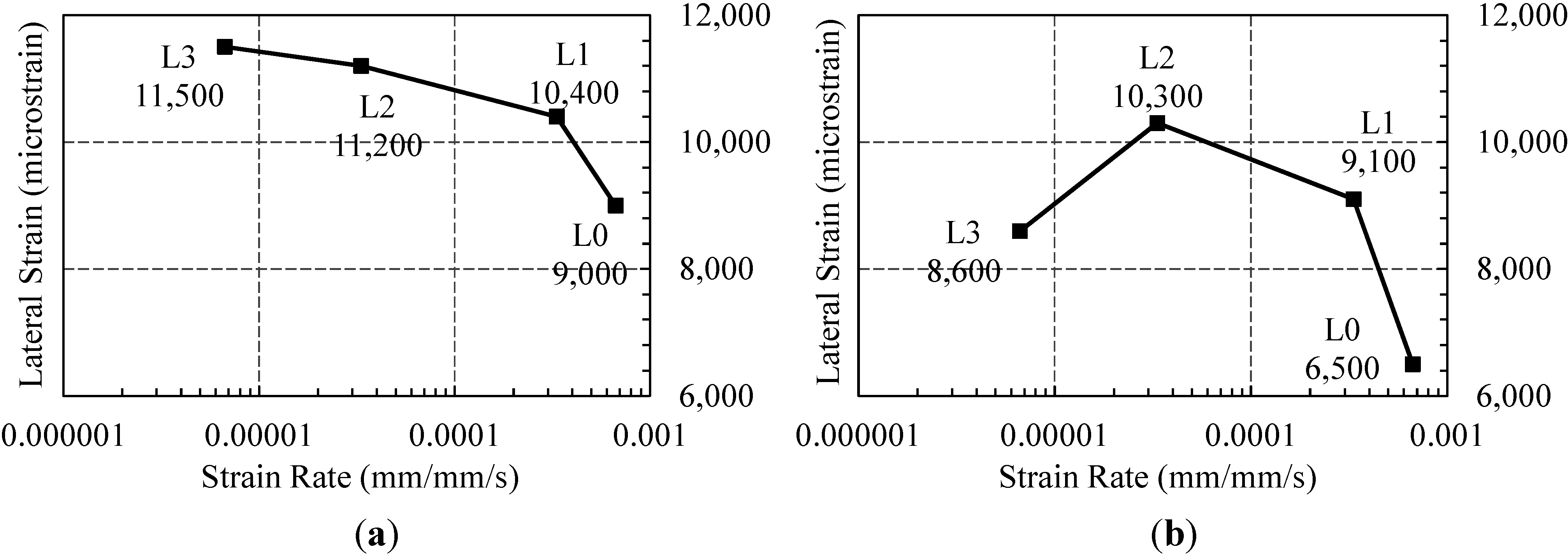
- FRP rupture strains tend to decrease with increasing strain rates, particularly in the case of low-strength concrete (about a 28% difference for low-strength concrete).
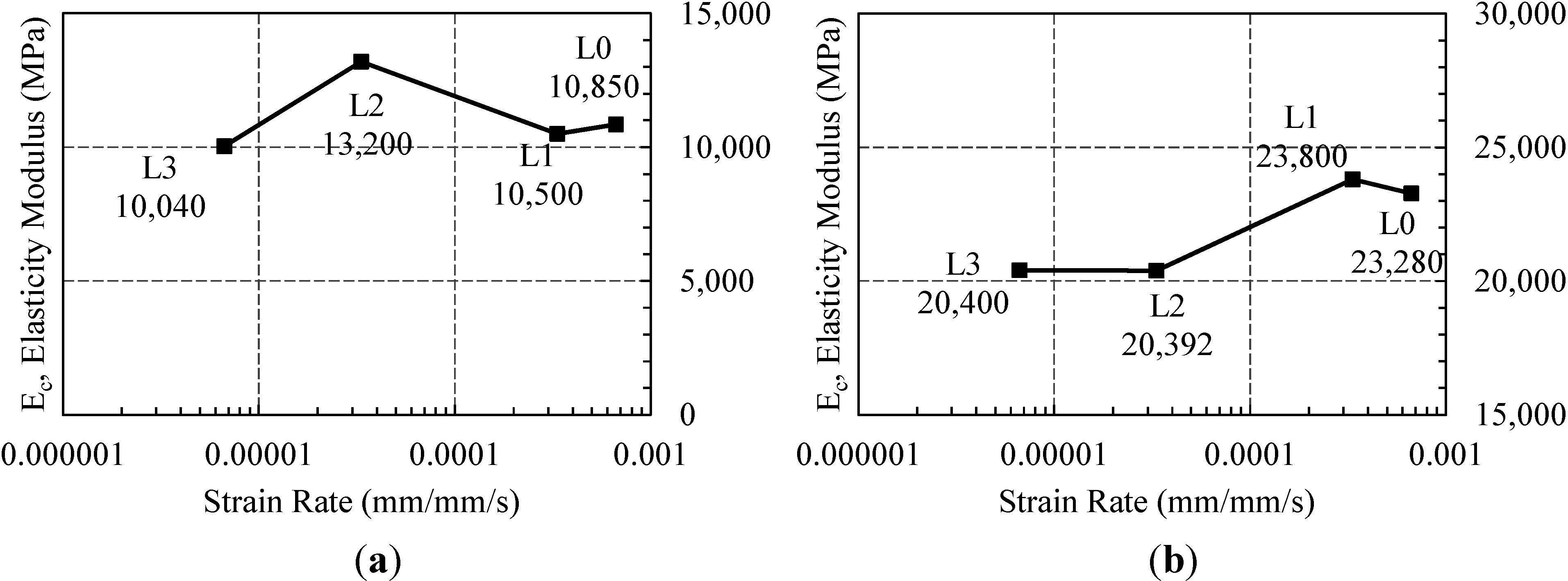
- In the case of low-strength concrete, the initial slope of the first branch of stress-strain curves is not considerably affected by the change in the strain rate. In the case of medium-strength prisms, the initial slope exhibits a vague tendency to increase with the increasing strain rate (increases about 15% between the lowest and highest rates). However, a clear increase is reported by Demir et al. [10] for medium-strength cylindrical specimens.
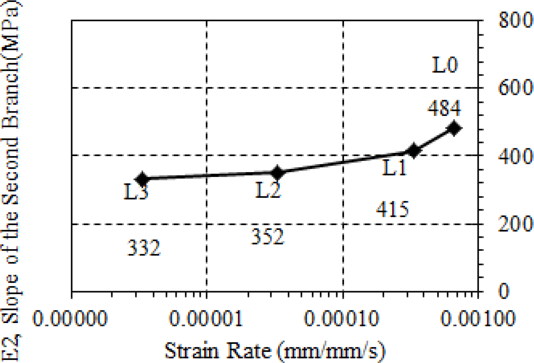
- Unlike the previous observations made for medium strength cylindrical specimens, the slope of the second branch of axial stress-strain diagrams of CFRP-confined low-strength concrete prisms increases with increasing strain rates (about a 45% increase). For medium-strength specimens, the post-peak descending branches obtained for different strain rates tend to get steeper for increased strain rates.
- CFRP confinement appears to be an effective retrofitting method against creep failures, even for sustained stress levels higher than the unconfined concrete strength (particularly for circular cross-sections, as was reported by the authors before [10]).
- For low- and medium-strength concrete prisms, sustained stress levels higher than 75% of the confined concrete strength (approximately corresponding to 2.76 f'co and f'co for low-strength and medium-strength prisms, respectively) may cause failure in a practical duration (i.e., during the service life of the structure).
- Power type relationships obtained for the variation of lateral strains under creep loads by time are similar for both the 48- and 96-h loading durations.
- Sustained loading did not have negative effects on confined concrete strengths and the ultimate axial deformation capacities of low- and medium-strength concrete specimens.
- All CFRP-confined prisms subjected to sustained loading reached slightly higher strengths than the monotonically-loaded ones.
- Although the total axial deformation capacity was not negatively affected, the residual strain capacities of specimens corresponding to the same loading duration group (48 or 96 h) decreased for increasing sustained stress levels.
- The increased duration of sustained loading led to slightly higher strength and ultimate strain values for medium-strength specimens.
- The efficiency of the confinement in the case of noncircular specimens was remarkably less than the efficiency reported by Demir et al. [10] for circular specimens.
Acknowledgments
Author Contributions
Conflicts of Interest
References
- Parvin, A.; Brighton, D. FRP composites strengthening of concrete columns under various loading conditions. Polymers 2014, 6, 1040–1056. [Google Scholar] [CrossRef]
- Ilki, A.; Kumbasar, N.; Koc, V. Strength and deformability of low strength concrete confined by carbon fiber composite sheets. In Proceedings of the Pavement Mechanics Symposium at the 15th ASCE Engineering Mechanics Conference, New York, NY, USA, 4 June 2002.
- Ilki, A.; Peker, O.; Karamuk, E.; Demir, C.; Kumbasar, N. FRP retrofit of low and medium strength circular and rectangular reinforced concrete columns. J. Mater. Civ. Eng. 2008, 20, 169–188. [Google Scholar] [CrossRef]
- Wu, Y.F.; Zhou, Y. Unified strength model based on Hoek-Brown failure criterion for circular and square concrete columns confined by FRP. J. Compos. Constr. 2010, 14, 175–184. [Google Scholar] [CrossRef]
- Karabinis, A.I.; Rousakis, T.C. Concrete confined by FRP material: A plasticity approach. Eng. Struct. 2002, 24, 923–932. [Google Scholar] [CrossRef]
- Mirmiran, A.; Shahawy, M.; Samaan, M.; EI Echary, H. Effect of column parameters on FRP-confined concrete. J. Compos. Constr. 1998, 2, 175–185. [Google Scholar] [CrossRef]
- Xiao, Y.; Wu, H. Compressive behavior of concrete confined by carbon fiber composite jackets. J. Mater. Civ. Eng. 2000, 12, 139–146. [Google Scholar] [CrossRef]
- Ozbakkaloglu, T.; Akın, E. Behavior of FRP-confined normal- and high-strength concrete under cyclic axial compression. J. Compos. Constr. 2012, 16, 451–463. [Google Scholar] [CrossRef]
- Bischoff, P.H.; Perry, S.H. Compressive behaviour of concrete at high strain rates. Mater. Struct. 1991, 24, 425–450. [Google Scholar]
- Demir, C.; Kolcu, K.; Ilki, A. Effects of loading rate and duration on axial behavior of concrete confined by fiber-reinforced polymer sheets. J. Compos. Constr. 2010, 14, 146–151. [Google Scholar] [CrossRef]
- Zhang, Y.; Su, S.; Su, J. The experimental research of carbon fiber confined concrete considering strain rate under uniaxial compression. Adv. Mater. Res. 2011, 163–167, 1485–1488. [Google Scholar] [CrossRef]
- Berthet, J.-F.; Ferrier, E.; Hamelin, P.; Al Chami, G.; Thériault, M.; Neale, K.W. Modelling of the creep behavior of FRP-confined short concrete columns under compressive loading. Mater. Struct. 2006, 39, 53–62. [Google Scholar]
- Kaul, R.; Ravindrarajah, R.S.; Smith, S.T. Deformational behavior of FRP confined concrete under sustained compression. In Proceedings of the Third International Conference on FRP Composites in Civil Engineering, Miami, FL, USA, 13–15 December 2006; pp. 207–210.
- Naguib, W.; Mirmiran, A. Time-dependent behavior of fiber-reinforced polymer confined concrete columns under axial loads. ACI Struct. J. 2002, 99, 142–148. [Google Scholar]
- Naguib, W.; Mirmiran, A. Creep analysis of axially loaded fiber reinforced polymer-confined concrete columns. J. Eng. Mech. 2003, 129, 1308–1319. [Google Scholar] [CrossRef]
- Wang, Y.; Zhang, D. Creep-effect on mechanical behavior of concrete confined by FRP under axial compression. J. Eng. Mech. 2009, 135, 1315–1322. [Google Scholar] [CrossRef]
- Zhang, D.J.; Wang, Y.F.; Ma, Y.S. Compressive behaviour of FRP-confined square concrete columns after creep. Eng. Struct. 2010, 32, 1957–1963. [Google Scholar] [CrossRef]
- Erdil, B.; Akyuz, U.; Yaman, I.O. Mechanical behavior of CFRP confined low strength concretes subjected to simultaneous heating–cooling cycles and sustained loading. Mater. Struct. 2012, 45, 223–233. [Google Scholar] [CrossRef]
- Demir, C.; Aydogmus, A.; Ilki, A. Short term creep tests of low strength rectangular concrete members jacketed with carbon FRP sheets. In Proceedings of the APFIS 2012—The Third Asia-Pacific Conference on FRP in Structures, Sapporo, Japan, 2–4 February 2012.
- Saiidi, M.S.; Johnson, R.; Maragakis, E.Z. Strain rate effects on strength of unidirectional FRP fabrics and bond to concrete. In Proceedings of the Third International Conference on FRP Composites in Civil Engineering, Miami, FL, USA, 13–15 December 2006; pp. 79–82.
- Mander, J.B.; Priestley, M.J.N.; Park, R. Theoretical stress-strain model for confined concrete. J. Struct. Eng. 1988, 114, 1804–1826. [Google Scholar] [CrossRef]
- Bažant, Z.P.; Panula, L. Practical prediction of time-dependent deformations of concrete. Mater. Struct. 1978, 11, 317–328. [Google Scholar]
- Prediction of Creep, Shrinkage and Temperature Effects in Concrete Structures; Report No. ACI 209R-82; American Concrete Institute (ACI): Detroit, MI, USA, 1992.
- Neville, A.M. Properties of Concrete; Pearson Education Limited: Essex, UK, 2003. [Google Scholar]
- Wang, L.M.; Wu, Y.F. Effect of corner radius on the performance of CFRP-confined square concrete columns: Test. Eng. Struct. 2008, 30, 493–505. [Google Scholar] [CrossRef]
- Wu, Y.F.; Wei, Y.Y. Effect of cross-sectional aspect ratio on the strength of CFRP-confined rectangular concrete columns. Eng. Struct. 2010, 32, 32–45. [Google Scholar] [CrossRef]
- Rousakis, T.C.; Karabinis, A.I. Adequately FRP confined reinforced concrete columns under axial compressive monotonic or cyclic loading. Mater. Struct. 2012, 45, 957–975. [Google Scholar] [CrossRef]
- Rousakis, T. Elastic fiber ropes of ultrahigh-extension capacity in strengthening of concrete through confinement. J. Mater. Civ. Eng. 2014, 26, 34–44. [Google Scholar] [CrossRef]
- Rousakis, T.C.; Tourtouras, I.S. RC columns of square section—Passive and active confinement with composite ropes. J. Compos. B Eng. 2014, 58, 573–581. [Google Scholar] [CrossRef]
© 2014 by the authors; licensee MDPI, Basel, Switzerland. This article is an open access article distributed under the terms and conditions of the Creative Commons Attribution license (http://creativecommons.org/licenses/by/3.0/).
Share and Cite
Demir, C.; Kucukkapili, A.; Doyrangol, D.; Ilki, A. The Effects of Loading Rate and Duration on the Axial Behavior of Low-Strength and Medium-Strength Noncircular Concrete Members Confined by Fiber-Reinforced Polymer Sheets. Polymers 2014, 6, 1685-1704. https://doi.org/10.3390/polym6061685
Demir C, Kucukkapili A, Doyrangol D, Ilki A. The Effects of Loading Rate and Duration on the Axial Behavior of Low-Strength and Medium-Strength Noncircular Concrete Members Confined by Fiber-Reinforced Polymer Sheets. Polymers. 2014; 6(6):1685-1704. https://doi.org/10.3390/polym6061685
Chicago/Turabian StyleDemir, Cem, Aygul Kucukkapili, Duygu Doyrangol, and Alper Ilki. 2014. "The Effects of Loading Rate and Duration on the Axial Behavior of Low-Strength and Medium-Strength Noncircular Concrete Members Confined by Fiber-Reinforced Polymer Sheets" Polymers 6, no. 6: 1685-1704. https://doi.org/10.3390/polym6061685