Article

Preparation and Characterization of Polyvinylidene Fluoride/Graphene Superhydrophobic Fibrous Films

by
Rasoul Moradi
1,
Javad Karimi-Sabet
2,*,
Mojtaba Shariaty-Niassar
1,* and
Mohammad A. Koochaki
3
1
Transport Phenomena and Nanotechnology (TPNT) Laboratory, School of Chemical Engineering, College of Engineering, University of Tehran, Tehran 14174, Iran
2
NFCRS, Nuclear Science and Technology Research Institute, Tehran 14155, Iran
3
Department of Chemical Engineering, Iran University of Science & Technology, Tehran 16846, Iran
*
Authors to whom correspondence should be addressed.
Polymers 2015, 7(8), 1444-1463; https://doi.org/10.3390/polym7081444
Submission received: 25 April 2015 / Revised: 13 June 2015 / Accepted: 8 July 2015 / Published: 6 August 2015

Abstract

:
A new strategy to induce superhydrophobicity via introducing hierarchical structure into the polyvinylidene fluoride (PVDF) film was explored in this study. For this purpose nanofibrous composite films were prepared by electrospinning of PVDF and PVDF/graphene blend solution as the main precursors to produce a net-like structure. Various spectroscopy and microscopy methods in combination with crystallographic and wettability tests were used to evaluate the characteristics of the synthesized films. Mechanical properties have been studied using a universal stress-strain test. The results show that the properties of the PVDF nanofibrous film are improved by compositing with graphene. The incorporation of graphene flakes into the fibrous polymer matrix changes the morphology, enhances the surface roughness, and improves the hydrophobicity by inducing a morphological hierarchy. Superhydrophobicity with the water contact angle of about 160° can be achieved for the PVDF/graphene electrospun nanocomposite film in comparison to PVDF pristine film.

Graphical Abstract

1. Introduction

In recent years, a considerable amount of studies have been focused on the superhydrophobic and superoleophobic surfaces which have, respectively, water and oil contact angles greater than 150° [1]. This innovative subject has applications in wide areas such as self-cleaning and anti-sticking coatings, smart materials, separation science, etc. Therefore, this remarkable property of extreme liquid wettability has been widely applied in both fundamental research and practical applications [2]. Biomimetics has a great amount of determination to fabricate micro and nanoscale superhydrophobic surfaces. For example, an investigation of naturally superhydrophobic materials, such as lotus leaves, demonstrated that the collaboration of a low surface energy compound (chemical factor) and the combination of micro- and nano-scaled surface structure (physical factor) are essential for superhydrophobicity [3,4].
In addition to natural occurrence, artificial and synthetic superhydrophobicity could be achieved using various chemical and physical methods, especially in nanoscale dimensions. A variety of techniques such as plasma treatment, lithography, sol–gel technology, nanoparticle deposition on smooth or roughened substrates, fluoroalkylsilane coatings, and phase separation of a multi-component mixture were used to fabricate superhydrophobic surfaces. These routes can generate superhydrophobic surfaces via either reducing the surface free energy of a rough surface or roughening a low surface energy material, or a combination of both [5]. Porous polymer coating is a versatile approach to surface characteristics engineering. Fluorinated polymers with low surface energy are naturally hydrophobic, chemically and environmentally stable. Hence, they are a group of the mostly-used materials to generate highly hydrophobic surfaces [6,7,8]. Polyvinylidene fluoride (PVDF) is one type of polymer that is commonly implemented in many film-based separation processes such as film distillation. PVDF is inherently hydrophobic with a water contact angle greater than 90°. For PVDF electrospun mats, this value is approximately 120° [9]. However, the wetting property is usually affected by the formation of the dense skin-layer on the film surface, which lowers the surface roughness and results in decreases of the water contact angle [10]. Therefore, application of the nanostructured materials such as carbon nanotubes (CNTs), graphene, and nanoparticles in modification of the surface morphology of PVDF is the subject of interest to improving superhydrophobicity. Among aforementioned nanofillers graphene, due to its hydrophobic properties, has recently received increasing attention in producing of graphene/polymer composites and engineering of the superhydrophobic surfaces [9,10,11]. Favorable enhancement of mechanical, electrical, and thermal properties of polymers by compositing theme with small amount of graphene has been investigated in many nanocomposite related works [12,13,14,15].
Improving the surface wetting resistance by using graphene and graphene oxide flakes have been studied previously [16]. This material is hydrophobic due to high density of carbon atoms in its surface. Furthermore, graphene increase the surface roughness that significantly affects the superhydrophobicity of the polymers [17]. Therefore, graphene interposing into the polymeric nanofibers is the potential approach to enhance the nanofibers’ surface roughness.
PVDF electrospun nanofibers have versatile characteristics. These properties make them applicable in various scientific fields. Considering this in the present study, we used an electrospinning method to fabricate PVDF porous and hydrophobic films for application in separation processes such as membrane distillation, which favors to implement highly hydrophobic films. In electrospinning, a great number of polymers and inorganic/polymer composites could be explored and, with development of this technology, it exhibits excellent applications in various fields [18,19,20]. Plenty of factors including polymer type, concentration of solutions, environmental parameters, and electrospinning conditions can effectively control the structures and morphologies of synthesized electrospun mats. In addition to the above, electrospinning is also a predominant and promising technique to develop superhydrophobic surfaces from some polymers with low surface energies and introducing the hierarchical structure to them. In recent years, several types of superhydrophobic surfaces, produced by electrospinning of PVDF, have been reported in the literature [21,22,23,24,25,26]. Additionally, it will be a good task to obtain a kind of novel film with PVDF/graphene electrospun thin layers coated on the surface of porous supports like polypropylene (PP) and polytetrafluoroethylene (PTFE). By using electrospinning, we can effectively prohibit the formation of skin-layer on the dried polymer surface, which has an undesirable impact on hydrophobicity, porosity, and permeation flux of the prepared membranes. Introducing the graphene into the PVDF nanofibers could enhance the hydrophobicity of the film. A combination of effects of the nanofibers’ network form by roughening the surface and inducing the hierarchical structure, making it feasible to achieve better characteristics of membranes.
In the present work, highly hydrophobic films have been prepared by using graphene composites of PVDF. Synthesized films have been characterized by various spectroscopic, microscopic, mechanical and wettability measurement methods. It was observed that a small loading of graphene (1.00 wt%) into the PVDF fibers induces the clear changes on the crystallization, morphology, mechanical strengths, and wettability of the prepared fiber-network films. The morphology characterization confirms that synthesized porous materials are homogeneous without skin-layer and with high surface roughness. Wettability tests illustrate the highly hydrophobic characteristics of these kinds of nanofibrous films in comparison with non-fibrous films. The graphene influences on the membrane-specific parameters, such as porosity and liquid entry pressure, were investigated.

2. Methodology

2.1. Materials

PVDF (MW = 400,000–600,000) was purchased from Sigma-Aldrich Chemical Co. (St. Louis, MO, USA), and was dried at 50 °C under vacuum for at least one day. Polypropylene porous sheets were prepared from Iran-membrane Co. (Tehran, Iran). N,N-dimetylacetamide (DMAc) and acetone, from Sigma, were used as the main solvents for preparation of polymer solutions. The dope solution was prepared by mixing the appropriate amounts of precursor polymer and graphene in DMAc/acetone solvent. Lithium chloride (LiCl) as an additive in electrospun dope solutions was obtained from Merck (Darmstadt, Germany) and used without any purification.
Graphene powder was synthesized via chemical method in our laboratory and was used after some pretreatments for modification of its surface. Graphite powder, in natural form, was purchased from Daejung Chemicals & Metals Co. (Shiheung-city, South Korea). NaNO3 and KMnO4 with analytical grade and 98% H2SO4, 30% H2O2, 5% HCl, methanol and hydrazine hydrate aqueous solution all were purchased from Merck.
All reagents were used as received or kept in good condition; any change in their properties is not valid. Double distilled water was purified with a deionizer resin and was used as a leaching solvent in the graphene synthesis and film preparation experiments.

2.2. Graphene Synthesis

Graphite oxide was synthesized from graphite based on the Hummers method [27]. Two grams graphite powder and 1 g NaNO3 were mixed with 46 mL 98% H2SO4 in an ice bath. KMnO4 (6 g) was added gradually, while stirring slowly to avoid the temperature reaching 20 °C. The prepared mixture was kept in an oven at 35 °C for 6 h, and was then diluted with distilled water (92 mL). To increase the oxidation rate, the temperature of the water bath was increased up to 98 °C and was maintained at this temperature for 15 min. The prepared suspension was treated with water (280 mL) and H2O2 (30%, 6 mL) until the color of the mixture changed to bright yellow. For synthesizing graphene oxide (GO) nan-sheets, the prepared mixture was separated and washed several times using HCl (5%), followed by water, to ensure the removing of sulfate chloride ions. Synthesized GO was filtrated by a medium fritted glass funnel, and dried in oven at 60 °C for 24 h.
For producing graphene (G) with reduction by hydrazine hydrate, prepared GO (300 mg) was mixed with water (100 mL), and the achieved inhomogeneous suspension was sonicated using the ultrasonic instrument (Hielscher, UP400S, Teltow, Germany), until it became transparent with no visible GO flakes. Then, hydrazine hydrate (1 mL) was added and the solution was refluxed in an oil bath at 100 °C for 24 h. This product was filtrated over a medium-fritted glass funnel, washed several times with distilled water and methanol, and dried on the funnel for 24 h. Figure 1a demonstrates the schematic of the reduction and oxidation reactions of the GO and G respectively. It should be mentioned that the synthesized G flakes were not defect-less and they likely contain the carboxylic, hydroxyl and other functional groups. Field emission scanning electron microscopy (FE-SEM) images of the synthesized GO and G nano-sheets are depicted in Figure 1b and further details represented in the results section.
Figure 1. (a) Schematic representation of the graphene (G) oxidation and graphene oxide (GO) reduction reactions. Red colored cycles represent the oxygen atoms (b) Scanning electron microscopy (SEM) images of the synthesized G and GO nano-sheets.
Polymers 07 01444 g001

2.3. Nanofibrous Film Preparation

A 10 wt% PVDF polymer dope solution for electrospinning was prepared by dissolving a pre-weighted PVDF in a mixture of DMAc and acetone with a weight ratio of 3:2 (60/40 wt%). The appropriate amount of LiCl (0.002 wt%) was added into the dope solution to improve dope electro-spin ability. The dope solution was kept at 50 °C under agitation for about 4 h until it was completely dissolved. Synthesized G powder was added to the mixed solution in appropriate amounts (5.00, 2.00, 1.50, 1.00, 0.50, 0.01 and 0.03 wt%) and the obtained colloidal solution was sonicated at 50 °C for 10 h. The homogenous dope solution was then cooled and degassed at room temperature before electrospinning.
The main challenge of electrospinning the prepared solution is related to the G and GO limited solubility in DMAc/acetone. Nonetheless, due to the ultrasonic treatment, and increasing of the solution viscosity, the prepared PVDF/G suspension was stable for over 4 h, which was enough time for electrospinning before the nano-sheets agglomeration.
The prepared PVDF/G solutions were spun into nanofibers net-like form, using the homemade electrospinning apparatus, which is schematically depicted in Figure 2. As shown, this set-up was equipped with a high voltage power supply and two electrospinning needles with the same inner diameters (300 µm). A positive voltage of 18 kV was applied across a distance of 15 cm between the needles and the grounded drum, which was rotating at 500 rpm. For increasing of the spinning throughput, we used two perpendicular syringe pumps connected to scanners for scanning along the drum and producing uniform films.
Figure 2. Schematics of the used electrospinning setup for producing of the fibrous films.
Polymers 07 01444 g002
The syringe injection rate was 15 mL/h and the nanofibers were spun over a course of 2 h to prepare continuous fibrous films with about 100 µm thicknesses. The collector drum surface was covered with the nonwoven PP sheet with 100 µm thickness and the electrospinning was performed on its surface. In order to eliminate any effect of residual solvents in the film, the produced nanofiber films were subsequently placed inside the fume cupboard under the vacuum condition at 60 °C overnight to ensure all solvents evaporated from the fresh films. For increasing the structural integrity of the as-spun nanofibrous film, post-heating treatment was carried out at 100 °C for 5 h. Then the obtained PVDF/G nanocomposite films were ready to use for characterization and ultimate applications as membranes for separation purposes. The characterizations of the synthesized films with properties such as hydrophobicity and mechanical strength were exhibited, as well as some novelties that are worth reporting in this paper. As depicted in Table 1, various types of pristine and composite electrospun films have been synthesized using electrospinning and phase inversion techniques respectively for obtaining nanofibrous (M0–M5) and non-fibrous (M'0, M'1) structure.
Table 1. Graphene concentration values in the precursor solutions and the method used for correspondent membrane preparation.
FilmSynthesis MethodG (wt%)
M0Electrospinning0.00
M1Electrospinning0.01
M2Electrospinning0.03
M3Electrospinning0.50
M4Electrospinning1.00
M5Electrospinning1.50
M'0Phase inversion0.00
M'1Phase inversion1.00
M0–M5 stand for the membranes which were prepared via electrospinning where M'0 and M'1 represent the membranes prepared by phase separation method.

2.4. Characterization and Testing

2.4.1. Dynamic Mechanical Analysis

The mechanical strength was examined using universal tensile test machine (Sanwood technology Co., Guang Dong, China) at ambient temperature. Prepared films were subjected to strain–stress measurements using tensile tester. Young’s modulus and elongation at breaking point were studied for both nanocomposite PVDF/G, PVDF/GO and pristine PVDF films. The specimens were cut into 5 mm (width) × 50 mm (length) test strips for mechanical strength analyses.

2.4.2. Porosity and LEP Examines

Gravimetric method was used to investigate the prepared electrospun films porosity. We used isopentane as the wetting liquid, due to hydrophobicity of PVDF films. The weight of wetting liquid contained in the film pores is related to porosity (ε) by Equation (1).
ε = ( w 1 w 2 ) / D 1 ( w 1 w 2 ) / D 1 + w 2 / D p
wheren w1 is the weight of the wet film, w2 is the weight of the dry film, D1 is the isopentane density (D1 = 0.62 g·cm−3) and Dp is the polymer density (DPVDF = 1.78 g·cm−3).
The liquid entry pressure (LEP) tests were carried out for the prepared porous hydrophobic membranes based on the previously reported method [28,29].

2.4.3. Microscopic and Spectroscopic Tests

SEM measurements were taken on F4160-Hitachi field emission scanning electron microscope (FE-SEM) (HITACHI, Tokyo, Japan). Samples were prepared by gold coating using a JFC-1100E ion sputtering device (JEOL, Tokyo, Japan).
Structural studies of the resulting films were carried out using Fourier-transform infrared spectroscopy (FT-IR) of nanofibers powder with KBr on a spectroscopy instrument (Bruker Tensor 27, Bruker Corporation, Billerica, MA, USA). X-ray diffraction (XRD), experiments for crystallographic studies have performed using X-ray diffraction (XRD) instrument (Inel, E.Quinox 3000, INEL, Artenay, France).
The Raman shifts of synthesized polymeric mats were obtained from Raman spectra using micro-Raman spectrometer (Bruker Senterra, Bruker Corporation, Billerica, MA, USA).

2.4.4. Hydrophobicity Testing

Contact angles tests were performed to investigate the wettability and hydrophobicity of the prepared films. Static water contact angles of the electrospun films were measured using the sessile drop method by a goniometer (Data-Physics OCA 20, Data Physics Instruments GmbH, Filderstadt, Germany) at ambient temperature. The water droplet of 2 µL volume was used in the measurements. More than five measurements on different locations were conducted for each sample. Dynamic results were recorded on the same goniometer. The contact angles of the advancing and receding droplet were obtained by changing the droplet volume between 2 to 10 µL.

3. Result and Discussion

3.1. Morphology and Crystallographic Studies

Pristine and composite PVDF nanofibers were successfully synthesized with the morphologies that have been depicted in 
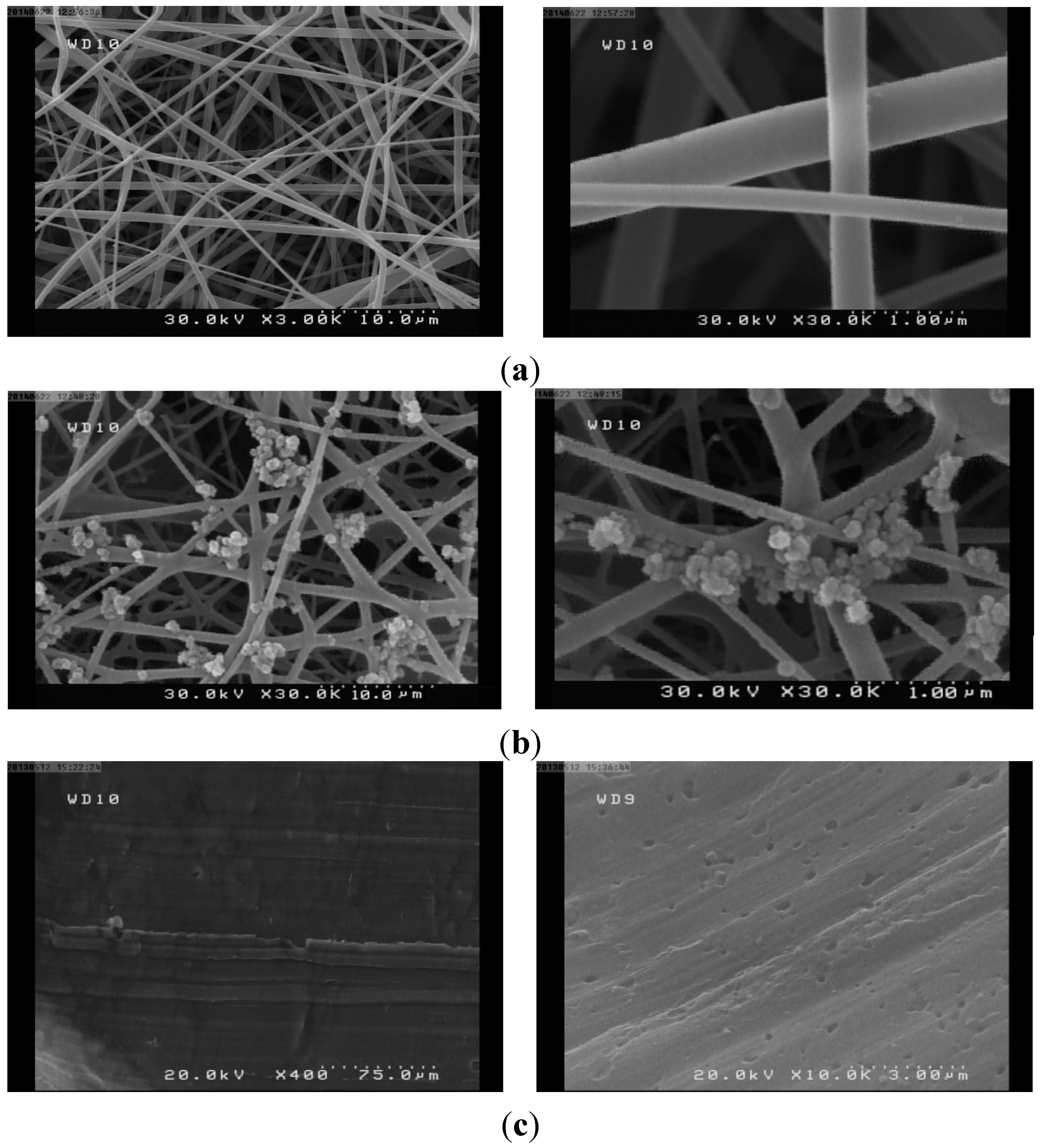
Figure 3. The FESEM micrographs demonstrate that addition of G in the PVDF precursor solution significantly influence the nanofibers morphology and thicknesses. The diameters of the nanofibers were increased in the presence of G and the increasing of its concentration in the precursor solution, cause the diameter of the produced fibers to increase. From Figure 3a, pristine PVDF nanofibrous film (produced by electrospinning of PVDF 10.0 wt% precursor solution), contains the fibers with diameters in the range of 100–250 nm. Fibers’ surfaces are very smooth, without any observable roughness. In the case of PVDF/G film (produced by electrospinning of PVDF/G, 10:1, precursor solution), as shown in 
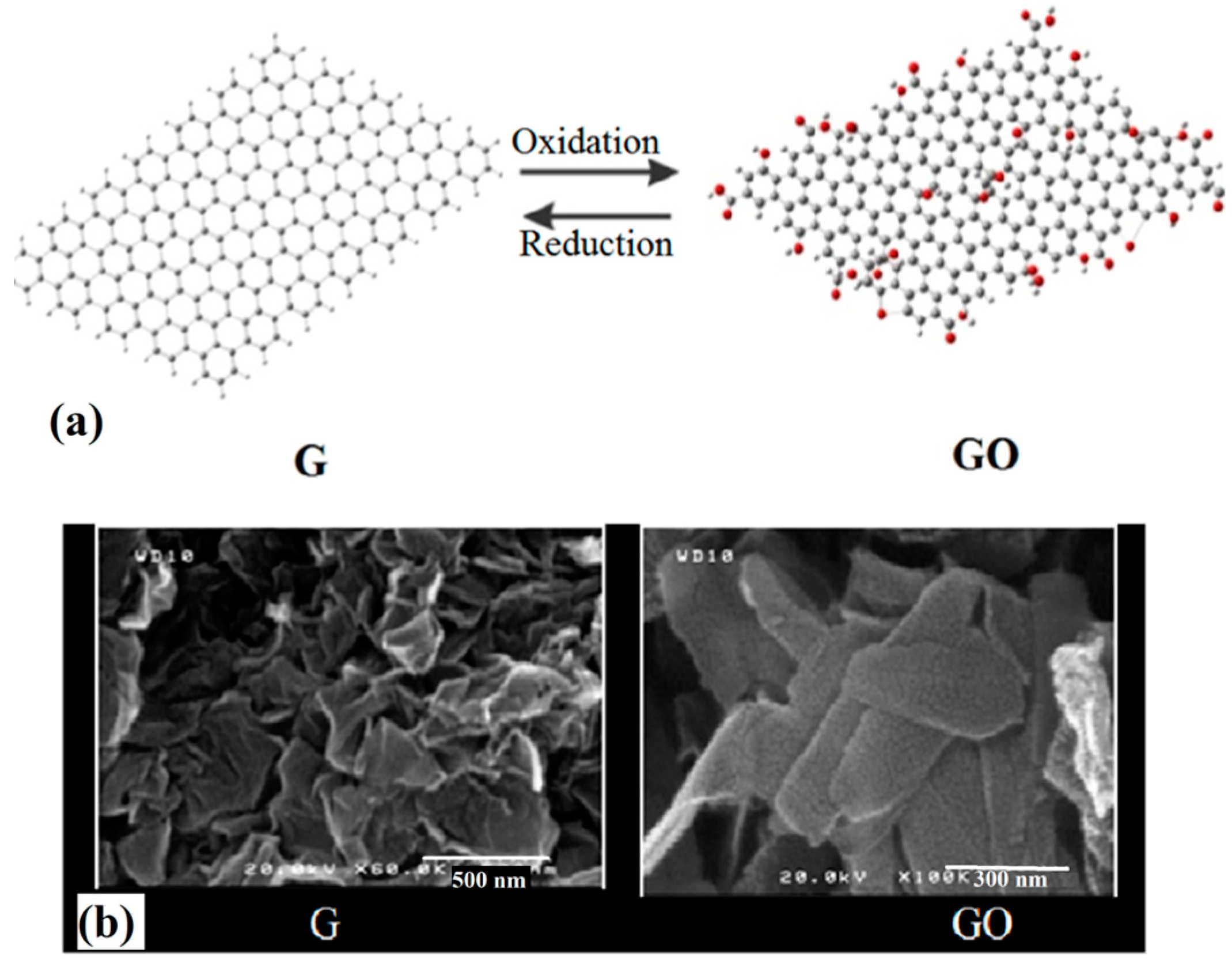
Figure 3b, the synthesized fibers’ diameters span the range of 350 nm–1 µm. In addition, the fibers’ surface roughening, due to G interposing, is depicted. The bead formation on the surface of the fibers is also observed, which is related to those G flakes that could not interpose inside the fibers during the electrospinning. Synthesized G flakes have with range of sizes (100–500 nm, from Figure 1b), However, during the PVDF/G solution preparation, as well as electrospinning process, G flakes likely get ruptured, which results in their size reduction.
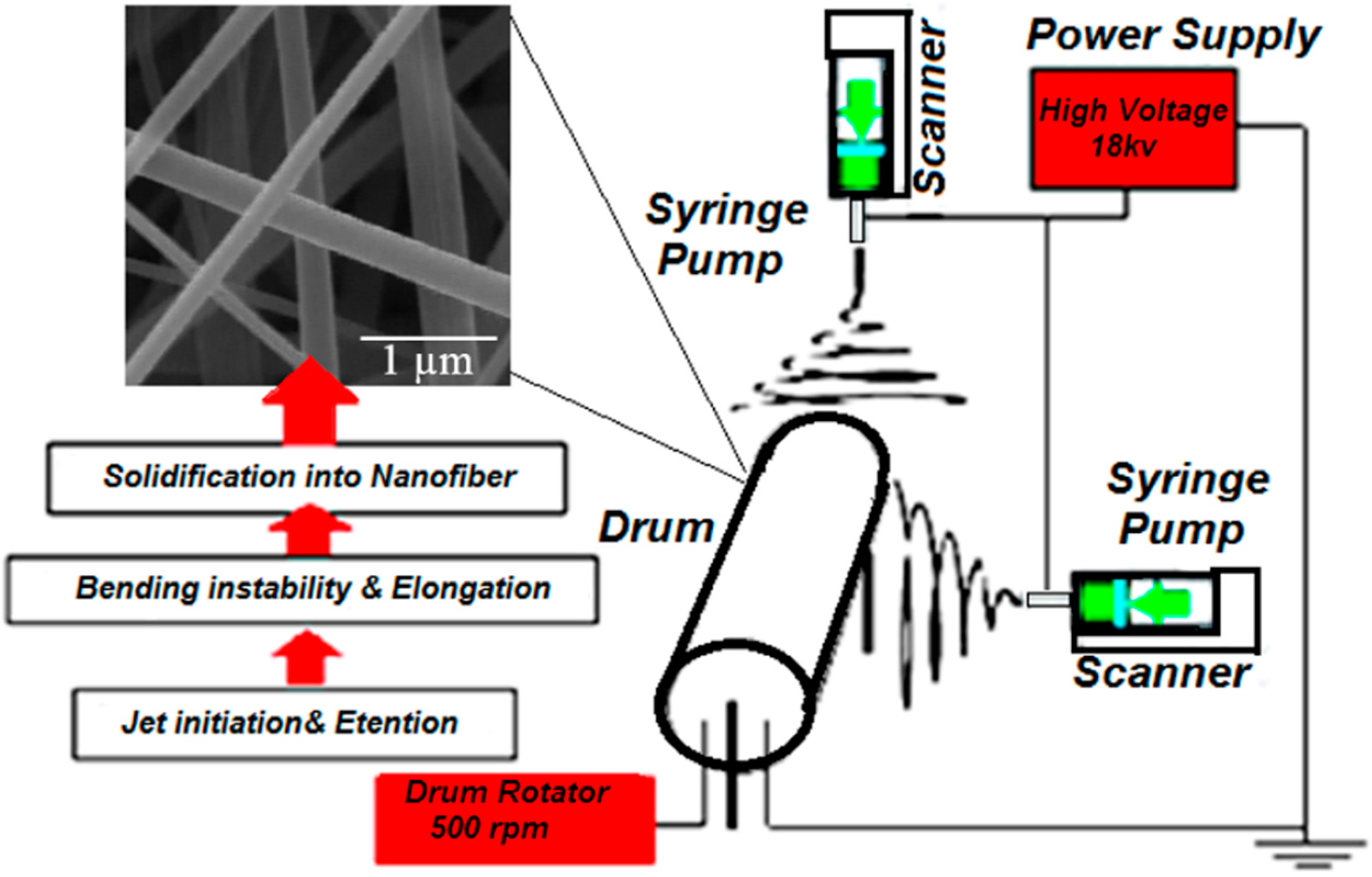
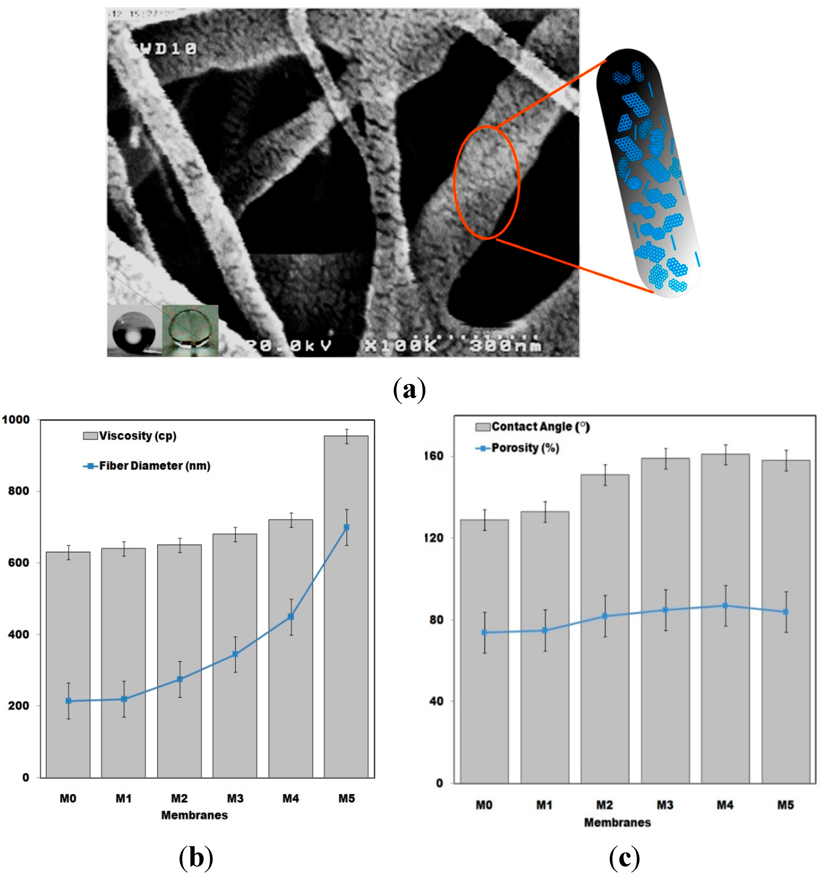
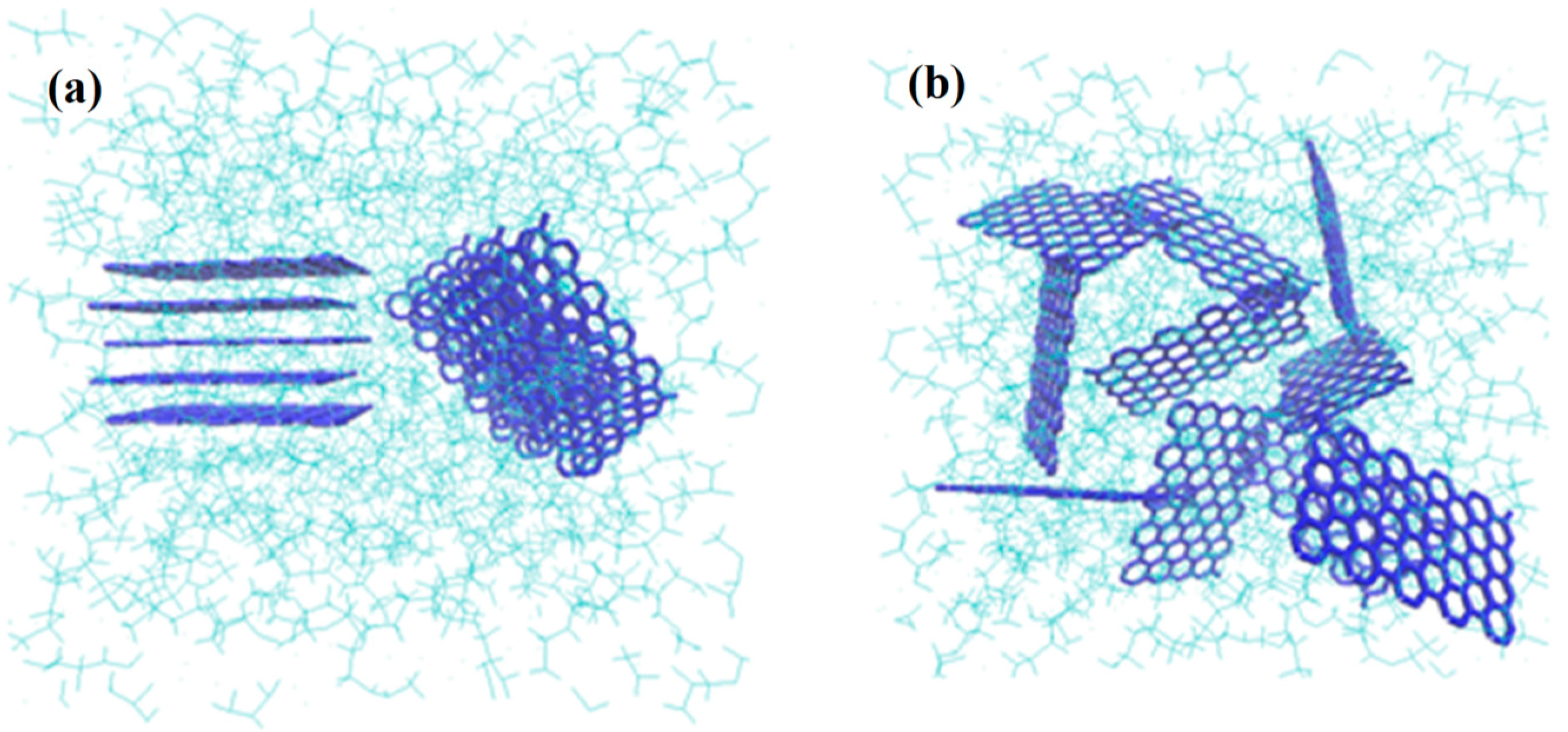
Proper arrangements of the G flakes inside the fibers plays an important role in the produced fibers final characteristics. In the presence of the strong electrical field that is applied for electrospinning, G flakes are likely to arrange parallel to the fiber axis (Figure 4a) and they rarely interpose into the fiber’s cross section, which is not favored from a mechanical strength point of view.
Figure 3. FESEM images of the prepared films: (a) M0; (b) M4; (c) M'0, (M0 and M4 represent the prepared electrospun membranes respectively with 0.0 and 1.0 wt% of grapheme; M'0 is for the pristine membrane prepared via phase separation method).
Polymers 07 01444 g003
Fabricated pristine and composite PVDF fiber thickness variation, as a function of G amount in various films, as well as the viscosity change of the polymeric precursor solution are represented in Figure 4b. It was observed that the viscosity of the precursor solution increases with G addition, which directly influences the synthesized fibers diameters. However, the average diameter for the produced PVDF nanofibers, M1, were 150 nm, whereas for the PVDF/G, M4, the average diameter of about 400 nm was obtained. It seems that viscosity increases in the PVDF/G solution could not be the sole reason of fiber diameters increasing. G flakes’ entrance into the PVDF fiber structure affects the fiber diameters by acting as reinforcement and nucleation agents. In addition, G addition affects the PVDF crystallization process that result in the changes of produced film hydrophobicity and porosity (Figure 4c).
Figure 4. (a) FE-SEM photograph of the PVDF/G nanofibrous membrane (M4). Water droplet image on the film surface and obtained wettability measurement image are also depicted. The schematic representation of G flakes interposed inside the PVDF fibers is shown at the right side of the image; (b) Precursor solution viscosity and fiber diameter changes of the prepared membranes; (c) Porosity and contact angle tests results for the prepared membranes. (M0, M1, M2, M3, M4 and M5 represent the membranes which were prepared via electrospinning with grapheme content of 0.0, 0.01, 0.03, 0.50, 1.0 and 1.5 wt % respectively).
Polymers 07 01444 g004
Another aspect is that G acting as the nucleation agent in polymer matrix improves the crystallization process in the formation of PVDF nanofibers. The surface roughness of PVDF/G nanofibers is higher than PVDF nanofibers, which directly affects the wettability properties of the nanofibers. XRD crystallographic analyses indicate that PVDF chains arrange in various crystallization forms in PVDF/G rather than pristine PVDF nanofibers. From Figure 5, increases in the intensities of the achieved diffraction peaks at 2θ = 18° and 20° is due to the enhancement of the crystallization zones in PVDF/G. In a similar study about the morphology of pure PVDF and PVDF/G composite films, which were prepared via phase inversion method, the same observations have been reported [8]. The diffraction peak near 2θ = 25° is characteristic of the PVDF α phase crystal structure. G addition affects polymorphism of the PVDF in favor of β phase. The disappearance of the diffraction peak at 2θ = 25° for PVDF/G, is due to formation of β phase in PVDF/G crystallization zones [30,31,32].
Figure 5. XRD patterns of (a) PVDF/G composite nanofibers (M4) and (b) pristine PVDF nanofibers (M0).
Polymers 07 01444 g005
Based on previous studies, the morphology of the PVDF film is also dependent on its formation mechanisms, where the existence of G in PVDF/G nanocomposite changes the morphology to assemble nanofibers with a diameter around 250 nm. Due to the good affinity of PVDF to carbon surfaces, like G sheets, the immobilization of PVDF chains on G sheets takes place, which act as the crystallization nuclei for the polymer chains. Previous studies also reported the similar phenomenon in the compositing of PVDF with carbon nanomaterials, such as carbon nanotubes [32]. G improves not only the morphology of the synthesized film but also affects the porosity of the prepared films (Figure 4c). The PVDF/G films likely have large pore-sizes and surface area in comparison with pure PVDF porous materials. As shown in Figure 3a and Figure 4a, in the cellular structure of the prepared mats different sizes of fibers span the range from 100 nm to a few micrometers, with observable surface roughness. This is because of the different sizes of G flakes that interposed inside the produced fibers’ structures and, hence, change their thicknesses in the wide range. Simultaneous presence of the nano and micro fibers is one of the novel properties of the synthesized PVDF/G films that promotes the film properties in some aspects of porosity, hydrophobicity, etc. [33,34,35,36,37].
SEM images from M4 and M1 films indicate that the net-like nanoporous structure is achievable for both; however, the nanofibers’ thicknesses in the case of M4 are greater than M1. Additionally, thicker PVDF/G nanofibers, in combination with better crystallization, cause changes to the effectiveness of their surface nanostructured morphology. This kind of structure could trap the air when it makes contact with water drops, enforcing the upward micro-pressures which strengthen the hydrophobicity.

3.2. Spectroscopic Analyses Results

For better understanding of the prepared film’s chemical structure, the FT-IR and micro-Raman studies have been performed. 
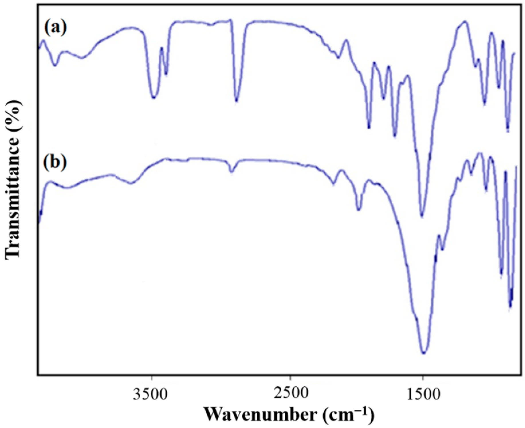
Figure 6 shows the obtained FT-IR spectra for the synthesized PVDF, PVDF/G electrospun films. FT-IR analysis was carried out for surface characterization of PVDF nanofibrous films in the range of 400–3800 cm−1. In the case of PVDF film, three strong peaks at about 850, 1400 and 1200 cm−1 were observed. The former two peaks were due to the C–F stretching vibration, and the latter one was due to the C–C bond of PVDF and the two weak bands appeared at 510 and 486 cm−1 were assigned to the CF2 bending vibration [37,38].
Figure 6. FT-IR spectra of (a) PVDF/G nanofibers (M4) and (b) pristine PVDF nanofibers (M0).
Polymers 07 01444 g006
For PVDF/G composite film, G affects the infrared absorption spectra with the appearance of absorption peaks at about 1700, 2000 and 3000 cm−1. The absorption bands around 1700 cm−1 show the existence of C–O bond, which is related to the bonds on the surface of G flakes. The strengthening of the broad peak around 3000 cm−1 confirms the formation of hydrogen bonds between the hydroxyl groups of G flakes and the fluorine of PVDF. In fact, this confirms that there are yet some hydroxyl, epoxide and carboxylic groups on the edges of G planes, which could bond to PVDF chains. For PVDF/GO composites, this peak is broadening in the wider range than PVDF/G due to numerous functional groups on the basal planes and edges of GO. Interactions between G flakes and PVDF chains could be helpful to enhance dispersion of G in the polymer matrix during the electrospinning process, in which G flakes are likely to move from the polymer matrix to the surface of the formed nanofibers [34,35]. There is also an increase in the intensity of the peak at around 1000 cm−1, with loading the G and GO into the PVDF, which corresponds to the increasing of the PVDF β phase [27,31].
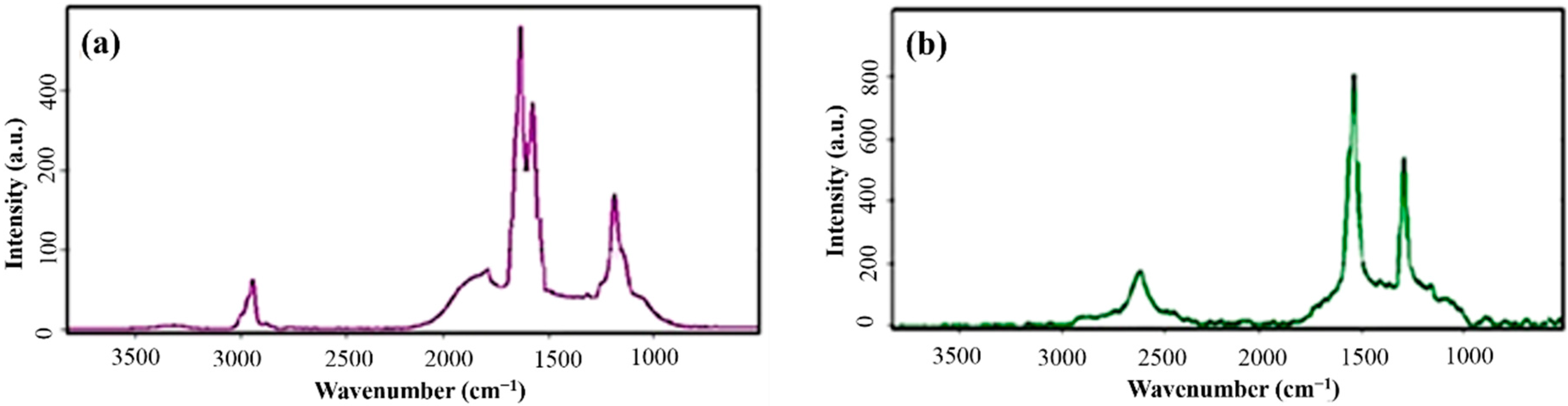
Raman spectroscopy was used for further study of the changes of G layers in combination with polymeric chains and the correspond influence on the PVDF structure. Micro-Raman spectra of the synthesized films for PVDF/G electrospun nanocomposite film and pure G powder are shown in Figure 7. Introduction of G nano-sheets into the polymer matrix, as well as intercalating of the polymer chains among G layers confirmed by the changes, could be proven by both of the appearance of the peaks and shifts. The three peaks of PVDF/G at 1234, 1589 and 2915 cm−1 correspond to D (defect) - band, G-band and 2D-band, respectively.
Figure 7. Micro-Raman spectra of (a) PVDF/G composite membrane and (b) synthesized pure graphene.
Polymers 07 01444 g007
In comparison with the G band at 1564 cm−1 of a few layers of pure graphene, this peak splits to two distinct peaks at 1531 and 1589 cm−1 in PVDF/G nanocomposite electrospun film. The splitting in the G-bond occurs due to the compositing of G by fluorinated compounds, such as PVDF, and has been reported in some earlier studies, especially about the molecular-decorated G by F2 [33], G interaction with aromatic molecules [34] or G doping by fluorinated hydrocarbons [35] in a plasma environment. The observation of G-bond splitting in prepared PVDF/G electrospun nanocomposite film may refer to the interaction between PVDF polymer chains and G flake surfaces.
Raman shift increasing by blending of the G with PVDF, related to intercalating of polymer between G platelets and their segregation. The observed red-shift in D-bond from 2600 cm−1 in pure G to 2915 cm−1 in PVDF/G electrospun nanocomposite film and also decreasing of its intensity, both indicating that G flakes exfoliated in PVDF polymer matrix which provides their good integration with polymer chains in the prepared electrospun films [
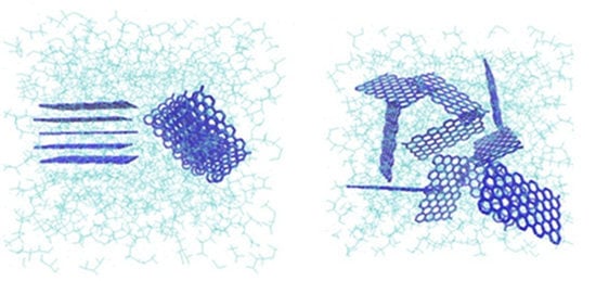
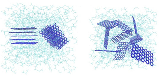
37]. The intercalation of G layers that is schematically shown in Figure 8a improves its exfoliation and dispersion in the polymer solution and enriches as depicted in Figure 8b. G flake exfoliation inside the PVDF matrix plays the important role in the observed morphological properties changes.
Figure 8. PVDF chains interposing among the G flakes: (a) intercalation and (b) exfoliation of the G layers (Green colored structure represents the polymer matrix wherein the graphene platelets with blue color are dispersed).
Polymers 07 01444 g008

3.3. Mechanical Strength Analyses Results

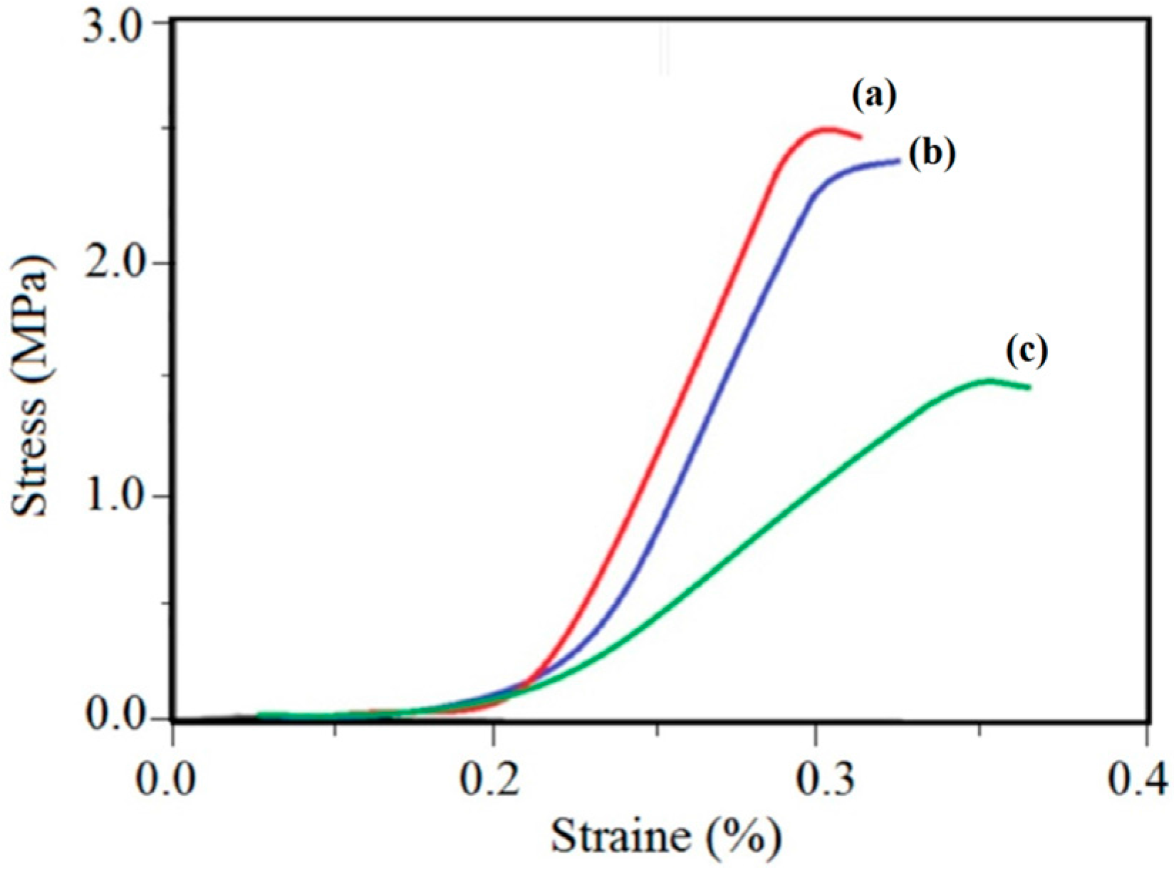
Figure 9 shows typical stress–strain curves of nanofibrous PVDF/G (M4, M5) and pristine PVDF (M0) films. It is noticeable that the tensile strength of nanofibrous PVDF film remarkably enhanced after G introducing. However, for the M5 membrane there is no sharp increasing in mechanical properties in compassion to M4.
The resulted stress-strain plot shows, that electrospun PVDF/G film exhibited higher tensile strength, tensile modulus and lower elongation and breaking point than PVDF films. The tensile strength of M4 nanofibrous film shows a peak value of 2.50 MPa, where for the electrospun M0 films a peak value is 0.70 MPa, therefore 3.5 times greater strength for produced electrospun films could be achieved by compositing of PVDF with G in the 100:1 weight ratio. In the case of M5 nanofibrous films, better mechanical properties are achieved in comparison with PVDF/G. However, considering the amount of the G introduced in M5 (1.5 wt%), the observed changes are not noticeable. The obtained mechanical strength analyses results of synthesized pristine and composite films have been represented in Table 2.
Figure 9. Stress-strain test results of the prepared membranes (a) M5, (b) M4 and (c) M0. (M0, M4 and M5 represent the prepared electrospun membranes respectively with 0.0, 1.0 and 1.5 wt% of geaphene).
Polymers 07 01444 g009
Table 2. Comparative analyses results for various prepared membranes.
FilmLEP (kPa)Contact angle (°)Porosity (%)Mean Pore Size (nm)Young Modulus (MPa)
M066 ± 4124 ± 273 ± 3450 ± 15410 ± 50
M170 ± 5135 ± 272 ± 3445 ± 10450 ± 80
M284 ± 5 135 ± 374 ± 3450 ± 10480 ± 40
M3110 ± 4155 ± 385 ± 3500 ± 15560 ± 50
M4122 ± 3161 ± 384 ± 3580 ± 20720 ± 60
M5130 ± 5160 ± 284 ± 3590 ± 20740 ± 80
M'056 ± 295 ± 354 ± 3200 ± 10420 ± 50
M'158 ± 2100 ± 555 ± 3190 ± 5490 ± 50
Explored crystalline zones in the PVDF/G nanofibers structure and intercalating of polymer chains between the G layers are two main reasons for improving the mechanical properties of nanocomposite PVDF/G films [8,30,33]. In addition, as mentioned earlier the simultaneous presence of nanofibers and microfibers, depicted in Figure 3b, generates a novel structure for nanocomposite films that significantly improves the mechanical properties of the PVDF/G composite films.
The observed increase in the fiber diameters due to graphene interposing at the same electrospinning conditions is one of the reasons for mechanical strength enhancement. For the fibers whose their matrixes include graphene, the fiber diameters increase up to micrometer sizes, while the fiber diameters in which the graphene could not interpose, or interpose in low amounts, do not increase and span in the nanometer range. Therefore, we encounter with the fiber-network structure the simultaneous presence of nanometer and micrometer fibers, which improve the tensile strength. Another reason that we used XRD experiments is the graphene influence on the PVDF crystallinity. The improvement in the crystalline zones due to graphene existence in the polymer matrix somehow affects the fibers’ mechanical strength. From Figure 9, an increase is observed in the Young modulus of the composite membrane, however the decline in the value of elongation at the break point is shown, which is the direct result of the enhancement in the crystalline zones in the PVDF/G film. Therefore, the fibers’ diameters and diameter distribution are increased by graphene addition that results in the mechanical strength improving. Since we applied the standard tensile test in all strain-stress experiments the sizes, thicknesses and weights of the examined specimens were equal, and the mass of the electrospun mat did not affect the results [38,39,40,41].

3.4. Hydrophobicity Test Results

In general, the hydrophobicity is evaluated by water contact angle, and higher hydrophobic films exhibits larger contact angle. The contact angle images of the prepared nanofibrous films are shown in Figure 10.
Figure 10. (a) Schematic representation of the surface structure effect (black colored) on the contact angle of the water droplet (blue colored) (b) Resulted images (black colored circles) and angles ( green colored lines) of water contact angle measurements (c) SEM images of related films. Respectively from right to left: M'0, M'1, M0 and M4. (M0, M4 represent the prepared electrospun membranes respectively with 0.0 and 1.0 wt% of geaphene. M'0, M'1 are for the membranes prepared via phase inversion method with graphene content of 0.0 and 1.0 wt%.)
Polymers 07 01444 g010
As introduced, fluoropolymers usually exhibit low surface energy, which may be attributed to intensive electronegative characteristics of the element fluorine. Thus, its attractive force to other substances is weak [3,36]. Due to its fluorinated composition, the PVDF films naturally exhibit high water contact angle values of around 85° to 130°, which confirm its inherent hydrophobicity. M'0 membrane which was prepared via phase inversion method the contact angle measurements results obtain the mean value of about 95° (Figure 10b). The water contact angle of about 128° was also reported, regarding to the preparation conditions [8,30]. However, the achieved hydrophobicity mainly depends to the film preparation method and the achieved morphology. As FESEM micrographs illustrate (Figure 3c), the prepared non-fibrous PVDF films possess the skin layer with the smoother and less porous surface.
Hydrophobicity is also improved by introducing G into the polymer matrix whereby the contact angles of the nanocomposite PVDF films were increased in comparison with the pristine PVDF films. From Figure 10b, the contact angle measurement for the non-fibrous PVDF/G film (M'1), results in the value of about 120°. Using electrospinning to prepare the fibrous films has the noticeable influence on the film wettability property, as the water contact angle of about 130° achieved for M0 (Figure 10b). In the case of electrospun PVDF/G film (M4), the water contact angle measured to be near 160°. The observed promotion in hydrophobicity suggests that the incorporation of G significantly affects the morphology and surface properties of the prepared nanofibers.
The SEM images of each tested film are represented under the related contact angle image in Figure 10c. The correspondent schematic representations in Figure 10a show how various surface structures influence the hydrophobicity of the engineered film. As shown, PVDF/G nanofibrous structures with the large surface roughness and area have larger water contact angles in comparison with virgin PVDF film and PVDF/G nanocomposite flat film. Additionally, adding a small amount of G to the PVDF precursor electrospun blend enhances the water contact angle significantly, where the 1.00 wt% of PVDF/G electrospun film we could achieve the superhydrophobicity with the water contact angle of 160°. Obtained hierarchical structures for PVDF/G is the result of three different structural stairs in the composition of prepared nanofibrous films. First hierarchy stair is formed by PP nonwoven sheets that we used as the membrane support, the second hierarchy is formed on it in the form of the fiber network, and the last one is the roughness of the fibers surfaces due to G presence.
To confirm and better comprehend the static contact angle results, dynamic contact angle measurements were performed. Figure 11 shows the obtained results for dynamic tests of the wetting phenomena. Herein, we employed droplet volume changing technique to measure the advancing and receding contact angles, so-called low rate dynamic contact angles. The graph of Figure 11a indicates the contact radiuses of the drop on the surface of PVDF/G film that were determined as a function of injection time. The graph of Figure 11b displays the dynamic contact angle as a function of the contact radius of the growing drop in triangle markers and the decreasing drop in squares. As can be seen, there is a linear relation between the droplet contact radius and time, which indicate a regime of constant speed of volume and contact line change. The average dynamic contact angles of PVDF/G nanofibrous film (M4) are obtained at the mentioned regime and the obtained values are represented in 
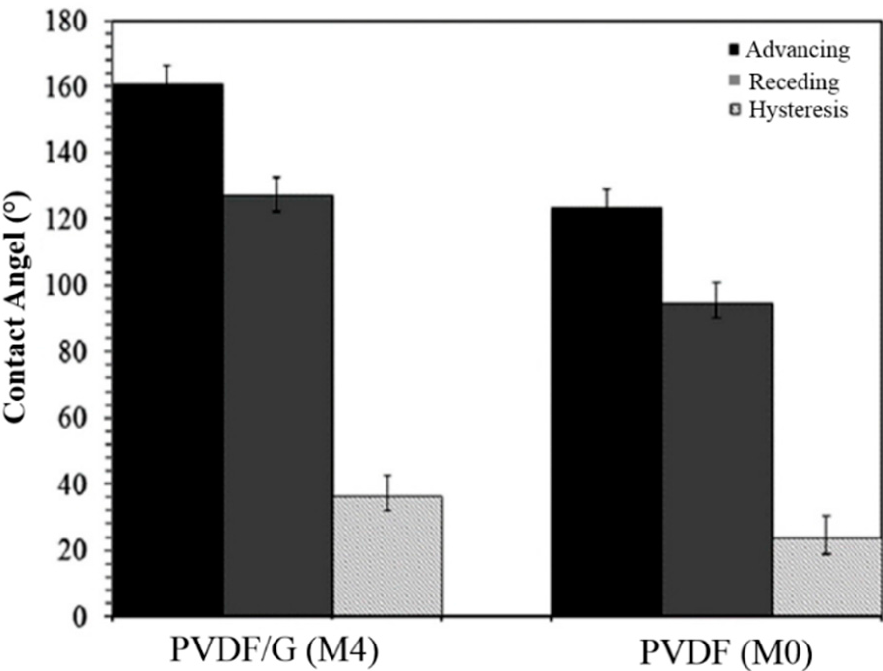
Figure 12 in comparison with the results of pristine PVDF nanofibrous film (M0). PVDF/G presents an average advancing contact angle of 161.2° ± 3.4° and the receding one is 127.5° ± 2.6° with a mean hysteresis of 34.3° ± 6°. In contrast, PVDF exhibits a mean advancing contact angle of 124.6° ± 2.5° and a receding one of 95.5° ± 2.3° with a mean hysteresis of 24.0° ± 5°. The highly hydrophobic characteristics of PVDF/G are again confirmed with the higher values of advancing and receding contact angles compared to those of PVDF. In addition the more hysteretic behavior of PVDF/G electrospun film probably due to a higher surface roughness.
Figure 11. The low-rate dynamic contact angles of the water on (a,b) composite M4 and (c,d) pristine M0 electrospun films. Triangle markers (∆) correspond to the advancing front of the sessile drop and squared markers (□) stand for the receding one; (a,c) Droplet contact radius as a function of injection and extraction time; and (b,d) Contact angle values variations with contact radius of dynamic drop are represented.
Polymers 07 01444 g011
Figure 12. Experimental dynamic contact angles of sessile water drops in the advancing, receding states and the related hysteresis for PVDF/G (M4) and PVDF (M0) films surfaces.
Polymers 07 01444 g012
The other reason for increasing of hydrophobicity by G addition into the PVDF fibrous mats is the increase in the prepared film surface porosity. Due to the elimination of the skin layer of the membranes by using electrospinning, in spite of phase inversion method, the obtained porosities for M0–M5 membranes were higher than M'0 and M'1 membranes (Table 2). In addition, as explained earlier, the membrane’s porosity increases with the amount of G nano-sheets added in the precursor PVDF solution. Higher contact angle values directly results in higher LEP values, which is an important factor for using the membranes in many separation processes, such as membrane distillation processes. Obtained results for LEP measurements are also represented in Table 2.
In the presented approach, the amount of used G is very little and it seems that the developed method is economic for achieving superhydrophobicity with wide range of applications. We will aim to employ the prepared PVDF/G films as the highly hydrophobic membranes in the membrane distillation process for separation purposes.

4. Conclusions

In this work, we observed that the addition of a small amount of graphene (G) into the PVDF polymer could improve the properties of hydrophobicity and mechanical strength. Electrospinning of the PVDF/G solution to convert it into nanofiber web structured films, induce the structural hierarchy, and increase the surface roughness, which clearly influences the hydrophobicity of the produced films by increasing the contact angle up to around 160°. The resulted is that using the electrospinning method for preparation of PVDF/G porous materials extremely limits the formation of a dense skin layer on top of the materials and enhances the specific surface area of both PVDF and PVDF/G porous materials. Furthermore, the addition of G in PVDF/DMAc/acetone solution influences the crystallization of PVDF during the solvent elimination via electrospinning and synthesizing of nanofibers. Micro-Raman studies perform the intercalation of PVDF chains among the G flakes. XRD study shows that G improves the PVDF crystallinity, which causes to the morphological change from micro-arrangement to nanostructured and hierarchical morphology. This change in morphology increases the porosity and roughness of the surface, which induces more air trapping when water droplets lie on it. It seems that this is the main reason for the increase in the apparent contact angle. By converting these materials to electrospun nanofibers, an increase in the surface specific area and porosity, which affects the superhydrophobicity, is observed. The obtained contact angle for the pristine PVDF non-fibrous film is about 125°, where for the 1.00 wt% of PVDF/G nanofibrous composite films this value is greater than 160°. Furthermore, FT-IR and micro-Raman analyses illustrate that there is a strong interaction between G flakes and PVDF chains. which result in improvement of mechanical strength of the prepared PVDF/G composite fibers. Stress-strain test results achieved for prepared films obviously demonstrate this increase in the mechanical strength of the prepared composite films compared to those pristine ones.

Acknowledgement

The authors would like to express their gratitude to the Advanced Systems Research Company for the technical and financial support.

Author Contributions

Rasoul Moradi has conducted the main part of the experimental work; Mohammad A. Koochaki has contributed in graphene synthesize experiments; Javad Karimi-Sabet, Mojtaba Shariaty-Niassar and Rasoul Moradi participated equally in results evaluation and manuscript editing. All authors have contributed equally in paper writing, preparation and submitting processes.

Conflicts of Interest

The authors declare no conflict of interest.

References

  1. McHale, G.; Shirtcliffe, N.J.; Newton, M.I. Super-hydrophobic and super-wetting surfaces: Analytical potential. Analyst 2004, 129, 284–287. [Google Scholar] [CrossRef]
  2. Shirtcliffe, N.J.; McHale, G.; Atherton, S.; Newton, M.I. An introduction to superhydrophobicity. Adv. Colloid Interface Sci. 2010, 161, 124–138. [Google Scholar] [CrossRef] [PubMed]
  3. Dorrer, C.; Ruhe, J. Some thoughts on superhydrophobic wetting. Soft Matter. 2009, 5, 51–61. [Google Scholar] [CrossRef]
  4. Avila, A.F.; Oliveira, A.M.; Lacerda, G.R.; Munhoz, V.C.; Santos, M.C.; Santos, P.F.; Triplett, M. A nano-modified superhydrophobic membrane. Mater. Res. 2013, 16, 609–613. [Google Scholar] [CrossRef]
  5. Zhang, X.; Shi, F.; Niu, J.; Jiang, Y.; Wang, Z. Superhydrophobic surfaces: From structural control to functional application. J. Mater. Chem. 2008, 18, 621–633. [Google Scholar] [CrossRef]
  6. Li, J.; Fu, J.; Cong, Y.; Wu, Y.; Xue, L.J.; Han, Y.C. Macroporous fluoropolymeric films templated by silica colloidal assembly: A possible route to super-hydrophobic surfaces. Appl. Surf. Sci. 2006, 252, 29–34. [Google Scholar] [CrossRef]
  7. Kwong, H.Y.; Wong, M.H.; Wong, Y.W.; Wong, K.H. Superhydrophobicity of polytetrafluoroethylene thin film fabricated by pulsed laser deposition. Appl. Surf. Sci. 2007, 253, 8841–8845. [Google Scholar] [CrossRef]
  8. Wang, K.W.; Hu, N.X.; Xu, G.; Qi, Y. Stable superhydrophobic composite coatings made from an aqueous dispersion of carbon nanotubes and a fluoropolymer. Carbon 2011, 49, 1769–1774. [Google Scholar] [CrossRef]
  9. Leenaerts, O.; Partoens, B.; Peeters, F.M. Water on graphene: Hydrophobicity and dipole moment using density functional theory. Phys. Rev. B 2009, 79, 235441–235445. [Google Scholar] [CrossRef]
  10. Zhao, X.; Zhang, Q.H.; Chen, D.J. Enhanced mechanical properties of graphene-based poly(vinyl alcohol) composites. Macromolecules 2010, 43, 2357–2363. [Google Scholar] [CrossRef]
  11. Liang, J.J.; Xu, Y.F.; Huang, Y.; Zhang, L.; Wang, Y.; Ma, Y.F. Infrared-triggered actuators from graphene-based nanocomposites. J. Phys. Chem. C 2009, 113, 9921–9927. [Google Scholar] [CrossRef]
  12. Rafiee, J.; Rafiee, M.A.; Yu, Z.Z.; Koratkar, N. Superhydrophobic to superhydrophilic wetting control in graphene films. Adv. Mater. 2010, 22, 2151–2154. [Google Scholar] [CrossRef] [PubMed]
  13. Wang, S.R.; Tambraparni, M.; Qiu, J.J.; Tipton, J.; Dean, D. Thermal expansion of graphene composites. Macromolecules 2009, 42, 5251–5255. [Google Scholar] [CrossRef]
  14. Yang, H.F.; Zhang, Q.X.; Shan, C.S.; Li, F.H.; Han, D.X.; Niu, L. Stable, conductive supramolecular composite of graphene sheets with conjugated polyelectrolyte. Langmuir 2010, 26, 6708–6712. [Google Scholar] [CrossRef] [PubMed]
  15. Lin, Z.Y.; Liu, Y.; Wong, C.P. Facile fabrication of superhydrophobic octadecylamine-functionalized graphite oxide film. Langmuir 2010, 26, 16110–16114. [Google Scholar] [CrossRef] [PubMed]
  16. Asmatulu, R.; Ceylan, M.; Nuraje, N. Study of superhydrophobic electrospun nanocomposites fibers for energy systems. Langmuir 2011, 27, 504–507. [Google Scholar] [CrossRef] [PubMed]
  17. Bognitzki, M.; CzadoScj, W.; Frese, T.; Schaper, A.; Hellweg, M.; Steinhart, M.; Greiner, A.; Wendorff, J.H. Nanostructured fibers via electrospinning. Adv. Mater. 2001, 13, 70–72. [Google Scholar] [CrossRef]
  18. Choong, C.L.; Shim, M.B.; Lee, B.S.; Jeon, S.; Ko, D.S.; Kang, T.H.; Bae, J.; Lee, S.H.; Byun, K.S.; Im, J.; et al. Highly stretchable resistive pressure sensors using a conductive elastomeric composite on a micropyramid array. Adv. Mater. 2014, 26, 3451–3458. [Google Scholar] [CrossRef] [PubMed]
  19. Givens, S.R.; Gardner, K.H.; Rabolt, J.F.; Chase, D.B. High-temperature electrospinning of polyethylene microfibers from solution. Macromolecules 2007, 40, 608–610. [Google Scholar] [CrossRef]
  20. Park, S.H.; Lee, S.M.; Lim, H.S. Robust superhydrophobic mats based on electrospun crystalline nanofibers combined with a silane precursor. Appl. Mater. Interfaces 2010, 2, 658–662. [Google Scholar] [CrossRef] [PubMed]
  21. Muthiah, P.; Hsu, S.H.; Sigmund, W. Coaxially electrospun PVDF-Teflon AF and Teflon AF-PVDF core-sheath nanofiber mats with superhydrophobic properties. Langmuir 2010, 26, 12483–12487. [Google Scholar] [CrossRef] [PubMed]
  22. Levi, N.; Czerw, R.; Xing, S.Y.; Lyer, P.; Carroll, D.L. Properties of polyvinylidene difluoride-carbon nanotube blends. Nano Lett. 2004, 4, 1267–1271. [Google Scholar] [CrossRef]
  23. Mago, G.; Kalyon, D.M.; Fisher, T.F. Membranes of polyvinylidene fluoride and PVDF nanocomposites with carbon nanotubes via immersion precipitation. J. Nanomater. 2008, 8, 1–8. [Google Scholar] [CrossRef]
  24. Acatay, K.; Simsek, E.; Ow-Yang, C.; Menceloglu, Y.Z. Tunable superhydrophobically stable polymeric surfaces by electrospinning. Angew. Chem. Int. Ed. 2004, 43, 5210–5213. [Google Scholar] [CrossRef] [PubMed]
  25. Ma, M.; Hill, R.M.; Lowery, J.L.; Fridrikh, S.V.; Rutledge, G.C. Electrospun poly(styrene-block-dimethylsiloxane) block copolymer fibers exhibiting superhydrophobicity. Langmuir 2005, 21, 5549–5554. [Google Scholar] [CrossRef] [PubMed]
  26. Singh, A.; Steely, L.; Allcock, H.R. Poly(bis(2,2,2-trifluoroethoxy)phosphazene) superhydrophobic nanofibers. Langmuir 2005, 21, 11604–1107. [Google Scholar] [CrossRef] [PubMed]
  27. Hummers, W.S.; Offeman, R.E. Aqueous graphene oxide dispersion: Bulk quantities attainable via chemical route. J. Am. Chem. Soc. 1958, 80, 1339–1339. [Google Scholar] [CrossRef]
  28. Feng, C.; Shi, B.; Li, G.; Wu, Y. Preparation and properties of microporous membrane from poly(vinylidene fluoride-co tetrafluoroethylene) (F2.4) for membrane distillation. J. Membr. Sci. 2004, 237, 15–24. [Google Scholar] [CrossRef]
  29. García, M.C.; Essalhi, M.; Khayet, M. Preparation and characterization of PVDFHFP copolymer hollow fiber membranes for membrane distillation. Desalination 2009, 245, 469–473. [Google Scholar] [CrossRef]
  30. Dao-an, Z.; Shilin, M.; Zhiyang, W.; Huanjun, L.; Zhujin, S.; Zhaoxia, J. Superhydrophobic polyvinylidene fluoride/graphene porous materials. Carbon 2011, 49, 5166–5172. [Google Scholar]
  31. Peng, Y.; Sun, B.; Wu, P. Two-dimensional correlation infrared spectroscopic study on the crystallization and gelation of poly(vinylidene fluoride) in cyclohexanone. Appl. Spectrosc. 2008, 62, 295–301. [Google Scholar] [CrossRef] [PubMed]
  32. Jung, N.; Kim, N.; Jockusch, S.; Turro, N.J.; Kim, P.; Brus, L. Charge transfer chemical doping of few layer graphenes: Charge distribution and band gap formation. Nano Lett. 2009, 9, 4133–4137. [Google Scholar] [CrossRef] [PubMed]
  33. Dong, X.C.; Shi, Y.M.; Zhao, Y.; Chen, D.M.; Ye, J.; Yao, Y.G. Symmetry breaking of graphene monolayers by molecular decoration. Phys. Rev. Lett. 2009, 102, 135501–135508. [Google Scholar] [CrossRef] [PubMed]
  34. Bruna, M.; Borini, S. Observation of Raman G-band splitting in top-doped few-layer graphene. Phys. Rev. B 2010, 81, 125421–125427. [Google Scholar] [CrossRef]
  35. Cheng, L.P.; Young, T.H.; Fang, L.; Gau, J.J. Formation of particulate microporous poly (vinylidene fluoride) membranes by isothermal immersion precipitation from the 1-octanol dimethylformamide poly(vinylidene fluoride) system. Polymer 1999, 40, 2395–2403. [Google Scholar] [CrossRef]
  36. Jin, Z.X.; Pramoda, K.P.; Goh, S.H.; Xu, G.Q. Poly (vinylidene fluoride)-assisted melt-blending of multi-walled carbon nanotube/poly (methyl methacrylate) composites. Mater. Res. Bull. 2002, 37, 271–278. [Google Scholar] [CrossRef]
  37. Bormashenko, Y.; Pogreb, R.; Stanevsky, O. Vibrational spectrum of PVDF and its interpretation. Polym. Test. 2004, 23, 791–796. [Google Scholar] [CrossRef]
  38. Adanur, S.; Liao, T. Fiber arrangement characteristics and their effects on nonwoven tensile behavior. Text. Res. J. 1999, 69, 816–824. [Google Scholar] [CrossRef]
  39. Khil, M.S.; Kim, H.Y.; Kim, M.S.; Park, S.Y.; Lee, D. Nanofibrous mats of poly(trimethylene terephthalate) via electrospinning. Polymer 2004, 45, 295–301. [Google Scholar] [CrossRef]
  40. Lee, K.H.; Kim, H.Y.; Khil, M.S.; Ra, Y.M.; Lee, D.R. Characterization of nano-structured poly(ɛ-caprolactone) nonwoven mats via electrospinning. Polymer 2003, 44, 1287–1294. [Google Scholar] [CrossRef]
  41. Huang, Z.; Zhang, Y.Z.; Ramakrishna, S.; Lim, C.T. Electrospinning and mechanical characterization of gelatin nanofibers. Polymer 2004, 45, 5361–5368. [Google Scholar] [CrossRef]

