1. Introduction
Existing earthquake-resistance methods focus primarily on encasing reinforced concrete (RC) columns using steel or fiber composite materials. A number of reports over the past two decades have shown that the most efficient strengthening method to resist the lateral earthquake loads for RC buildings is to use steel bracing, and retrofitted steel bracing can strengthen earthquake-damaged buildings and increase the seismic capacity of existing RC buildings [
1,
2,
3,
4,
5,
6,
7].
Viswanath
et al. [
8] analytically showed that X-bracing significantly increases the structural stiffness of buildings, and reduces the maximum inter-story drift. Triangulated- and X-bracing systems have been used in five-story RC buildings, without considering seismic design, and a significant strengthening effect was found [
9]. Scale tests for seven-story RC buildings reinforced using steel bracing have been reported, and an enhancement of vertical and horizontal resistance was found just prior to buckling failure of the bracing in response to earthquake loadings [
10]. An RC school building was strengthened using post-tensioned rod braces, which increased the moment capacity rather than increasing the ductility [
11]. Direct connection has been shown to exhibit favorable earthquake resistance compared with indirect connection [
1,
12,
13,
14,
15].
Seismic reinforcement using steel braces typically exhibits brittle failure at the connections or buckling failure of the braces. There have been a number of reports of methods to address the buckling failure of the braces. These have mostly focused on the buckling restrained braced (BRB) system. An analytical study to calculate the confidence parameters of buckling failure of a four-story steel office building was carried out, and indicated that carefully assessing the braced steel frames was particularly important, especially to prevent collapse [
16].
In Japan, BRB frames have become increasingly popular because of the favorable earthquake resistance [
17]. A new type of bidirectional-resistant ductile end diaphragm using BRB for applications in bridges was introduced [
18]. A BRB device encased in steel tubing and mortar has been reported [
19], and the authors found effective performance in response to cyclic loading. A buckling restrained braced frame (BRBF) with a pinned moment connection has been reported, favorable performance in mitigating residual drift, soft-story deformation, and preventing undesirable failure modes in the beam-column connection, and was analyzed using nonlinear dynamic analysis [
20]. A nine-story building reinforced with a special concentrically braced frame (SCBF), a buckling restrained braced frame (BRBF) and a mega-braced frame (MBF) was simulated to evaluate the seismic performance of these different bracing configurations. The MBF series exhibited the most effective resistance to lateral drift, even though it was relatively low-weight [
21]. A method to inhibit buckling failure of the braces has been reported, which uses non-compression braces installed with sliding equipment at the brace connection [
22].
Recently, Ju
et al. [
23] reported a technique for non-compression X-bracing systems using carbon fiber anchors for seismic strengthening of RC structures. A carbon fiber is a bundle of yarn-type carbon. Using cyclic load tests, they verified that the carbon fiber anchors have advantages compared with conventional steel X-bracing systems, including an improved strength-to-weight ratio of carbon fiber, compression-free bracing, and confinement using carbon fiber sheets at the brittle concrete-steel joint area. They also reported that further work is needed to optimize details of the connection between the carbon fiber bracing and columns.
In this paper, we describe a new technique for non-compression X-bracing using carbon fiber composite cable (CFCC) for seismic strengthening of RC structures. This CFCC X-bracing system consists of CFCC bracing and bolt connections between the structural members and the terminal fixer of the CFCC, rather than the conventional X-bracing system, which is commonly used with steel bracing. We report the seismic performance of an RC frame reinforced with CFCC X-bracing using cyclic loading tests, and the maximum load carrying capacity and deformation were characterized, as well as hysteresis of the lateral load–drift relation.
2. Seismic Strengthening Using CFCC X-Bracing
2.1. CFCC
Tokyo Rope [
24] developed CFCC, a structural reinforcing cable, formed of carbon fibers and thermosetting resins with a polyester skin, and using a new composite technology to create a stranded cable. Thus, the structural behavior of CFCC is similar to that of carbon fiber strands, which has no plastic behavior.
Figure 1 shows optical images of the CFCC, including the terminal fixer. CFCC exploits the excellent mechanical properties of carbon fiber, and exhibits a high tensile strength (approximately equal to that of steel strands for prestressed concrete, as discussed later), a high tensile modulus (similar to that of steel strands for prestressed concrete), is lightweight (approximately one-fifth the mass of steel strands), has good corrosion resistance (high acid and alkali resistance), is non-magnetic, flexible (the stranded configuration of the cables allows them to be easily coiled), and a low linear expansion rate (the coefficient of linear expansion is approximately 1/20 of that of steel).
Figure 1.
Optical images of standard CFCC (Tokyo Rope, [
24]): (
a) 19-strand, 25.5 mm diameter and (
b) seven-strand, 12.5 mm diameter; (
c) A terminal fixer for a single cable made by expansive material filling method (ES-type) and (
d) a terminal fixer for multiple cables (EM-type). Reprinted with permission from reference [
24]. Copyright 2013, Tokyo Rope.
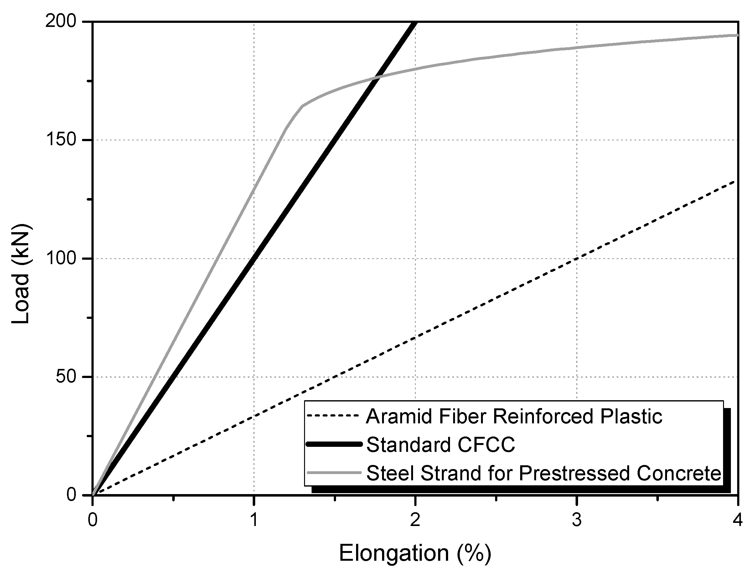
Figure 2 shows the load-elongation characteristics of standard CFCC, as well as those of steel strand for prestressed concrete and aramid fiber reinforced plastic (AFRP) [
24]. The tensile modulus of CFCC is approximately twice that of AFRP, and approximately equal to that of steel strand for prestressed concrete. CFCC has a high tensile modulus, which is similar to that of steel strand for prestressed concrete.
Table 1 lists the material properties of standard CFCC. The tensile elastic modulus of the standard CFCC is in the range 130–160 kN/mm
2. As will be described later, the ultimate load at failure of seven-strand CFCC with a diameter of 15.2 mm, used in this study, is 270 kN.
Figure 2.
Load–elongation relations of standard carbon fiber composite cable (CFCC) (Tokyo Rope, [
24] 2013). Reprinted with permission from reference [
24]. Copyright 2013, Tokyo Rope.
Figure 2.
Load–elongation relations of standard carbon fiber composite cable (CFCC) (Tokyo Rope, [
24] 2013). Reprinted with permission from reference [
24]. Copyright 2013, Tokyo Rope.
CFCC reinforcement has been used mainly in the field of civil engineering, including tendons in pre-stressed concrete bridges, cantilever cables and external cables of the pre-stressed concrete bridges, tendons of the ground anchors, and stay cables for strengthening the catwalks of bridges [
24]. CFCC reinforcement techniques for buildings have not yet been investigated. In this study, we describe for the first time the technique of X-bracing using CFCC for seismic reinforcement of RC buildings.
Table 1.
Specification of the standard CFCC cables.
Table 1.
Specification of the standard CFCC cables.
| Configuration and diameter a | Diameter φ (mm) | Effective cross section b (mm2) | Tensile strength at break (kN) | Nominal mass density (g/m) | Tensile elastic modulus (kN/mm2) |
|---|
![Polymers 07 01480 i001]() | U, 5.0 φ | 5.0 | 15.2 | 38 | 30 | 167 |
![Polymers 07 01480 i002]() | 1 × 7, 7.5 φ | 7.5 | 31.1 | 76 | 60 | 155 |
| 1 × 7, 10.5 φ | 10.5 | 57.8 | 141 | 111 | 155 |
| 1 × 7, 12.5 φ | 12.5 | 76.0 | 184 | 145 | 155 |
| 1 × 7, 15.2 φ | 15.2 | 115.6 | 270 | 221 | 155 |
| 1 × 7, 17.2 φ | 17.2 | 151.1 | 350 | 289 | 155 |
![Polymers 07 01480 i003]() | 1 × 19, 20.5 φ | 20.5 | 206.2 | 316 | 410 | 137 |
| 1 × 19, 25.5 φ | 25.5 | 304.7 | 467 | 606 | 137 |
| 1 × 19, 28.5 φ | 28.5 | 401.0 | 594 | 777 | 137 |
![Polymers 07 01480 i004]() | 1 × 37, 35.5 φ | 35.5 | 591.2 | 841 | 1,185 | 127 |
| 1 × 37, 40.0 φ | 40.0 | 798.7 | 1,200 | 1,529 | 145 |
2.2. CFCC X-Bracing
The CFCC X-bracing system for RC buildings consists of flat-plate and protrusion configurations, as shown in
Figure 3. Following coring 30-mm-diameter holes in the existing beam, steel devices for connecting of the flat-plate and protrusion-type reinforcements were mechanically installed using prestressing steel bars through the holes at both edges of the beam. The CFCC was cross-braced using a terminal fixer, as shown in
Figure 3c, and bolted to steel connecting devices. The flat-plate and protrusion type CFCC X-bracing systems use a bolt-nut connection method, which enables control over the deflection of the bracing.
Figure 3.
Seismic reinforcement methods using CFCC X-Bracing: (a) Flat-plate and (b) protrusion configurations. (c) Details of an individual CFCC reinforcement.
Figure 3.
Seismic reinforcement methods using CFCC X-Bracing: (a) Flat-plate and (b) protrusion configurations. (c) Details of an individual CFCC reinforcement.
The structural behavior of the CFCC X-bracing is indicated in
Figure 3a. When a lateral force acts, as shown by P1, the ascending brace experiences a tensile force
T1 and the descending brace has no compressive force;
i.e.,
C1 = 0. For a lateral force P2, the descending brace has a tensile force
T2 and the ascending brace has no compressive force, so
C2 = 0. There is no compressive stress on the CFCC X-bracing system in response to lateral loading.
3. Structural Tests
3.1. Material Characteristics of Concrete, Steel Rebar and CFCC
The specified compressive strength of the concrete used in the tests was 24 MPa. The results of cylindrical compressive tests were 19.0 MPa for 14 days and 24.3 MPa for 28 days, as listed in
Table 2. The specified yield strength of the steel reinforcing bar (rebar) used in the test specimens was 400 MPa. Two diameters of rebar were used: D13 for the main rebar of the column and D6 for the hoop. The tensile strength of steel rebar from using a universal testing machine (UTM) was 567.2 ± 8.2 MPa for D13 and 538.0 ± 3.0 MPa for D6.
Table 2.
Material properties of the concrete.
Table 2.
Material properties of the concrete.
| Specified strength (MPa) | Compressive strength (MPa) |
| 14 days | 28 days |
| 24 | 19.3 | 23.1 |
| 18.3 | 19.9 |
| 19.4 | 29.9 |
| Average | 19.0 | 24.3 |
The properties of the 1 × 7, 15.2 φ used here are listed in
Table 1. We used a terminal fixer for multiple cables (EM). The diameter of the CFCC was φ = 15.2 mm, the effective cross section was 115.6 mm
2, the tensile strength at break was 270 kN, the nominal mass density was 221 g/m, and the tensile elastic modulus was 155 kN/mm
2.
3.2. Design, Variables and Fabrication of Test Specimens
Specimens were designed based on the frame of a typical Korean school building [
25], and fabricated for cyclic load tests to investigate the reinforcement properties of the CFCC X-bracing system. The building was a three-story RC structure designed in the 1980s, without seismic reinforcement. The structure consisted of RC frames with spandrel brick walls in the longitudinal direction, and in-filled brick walls in the transverse direction. One span of the exterior frame in the longitudinal direction corresponds to columns, the beam and the spandrel brick wall, as shown in
Figure 3. This was selected for the tests because the seismic capacity in the transverse direction with the in-filled brick walls is higher than that in the longitudinal direction [
26].
Three types of specimen were designed and fabricated for the experimental tests: a control test specimen (not reinforced), as shown in
Figure 4, a test specimen reinforced with CFCC X-bracing using the flat-plate, as shown in
Figure 3a, and a test specimen strengthened with the CFCC X-bracing using the protrusion configuration, as shown in
Figure 3b.
Table 3 lists details of each of the specimens.
Figure 4.
Details of the control specimen.
Figure 4.
Details of the control specimen.
Table 3.
Summary of the specimens used in this study. RCFR: Control specimen without CFCC X-bracing; CFCC-1: CFCC X-bracing (flat-plate); CFCC-2: CFCC X-bracing (protrusion).
Table 3.
Summary of the specimens used in this study. RCFR: Control specimen without CFCC X-bracing; CFCC-1: CFCC X-bracing (flat-plate); CFCC-2: CFCC X-bracing (protrusion).
| Specimens | Column clear height, ho (mm) | Column depth, D (mm) | ho/D | Strengthening material | Strengthening types | Connection method |
|---|
| RCFR | 1680 | 210 | 6.72 | - | - | - |
| CFCC-1 | 1680 | 210 | 6.72 | CFCC 1 × 7, 15.2 φ | Flat-plate | Bolt-nut system |
| CFCC-2 | 1680 | 210 | 6.72 | CFCC 1 × 7, 15.2 φ | Protrusion | Bolt-nut system |
All specimens had identical dimensions and arrangements of rebar. The cross-section of the columns was 210 × 300 mm, and the ratio of column clear height to the depth
ho/
D = 6.72. Each specimen was prepared with 10-D13 type SD40 main rebar, reinforced with shear reinforcement D6 steel bars at 180-mm intervals. Beams were fabricated to install the CFCC X-bracing, which were designed to have same behavior with a stub at the top, as shown in
Figure 4. The stub, with a high stiffness, was installed at the top of each specimen to provide confinement for the columns. The spandrel brick wall was 480 mm high, and constructed using B-type brick;
i.e., 190 mm long, 90 mm wide and 57 mm thick. The compressive strength of the brick was 8 MPa.
3.3. Testing Procedure
The main purpose of the tests was to investigate the seismic resistance of the non-compression CFCC X-bracing in terms of the maximum load-carrying capacity, deformation, and hysteresis of the lateral load–drift relations.
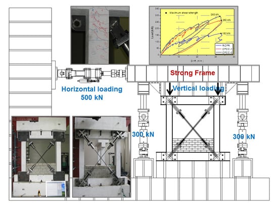
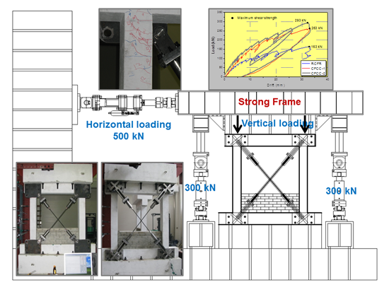
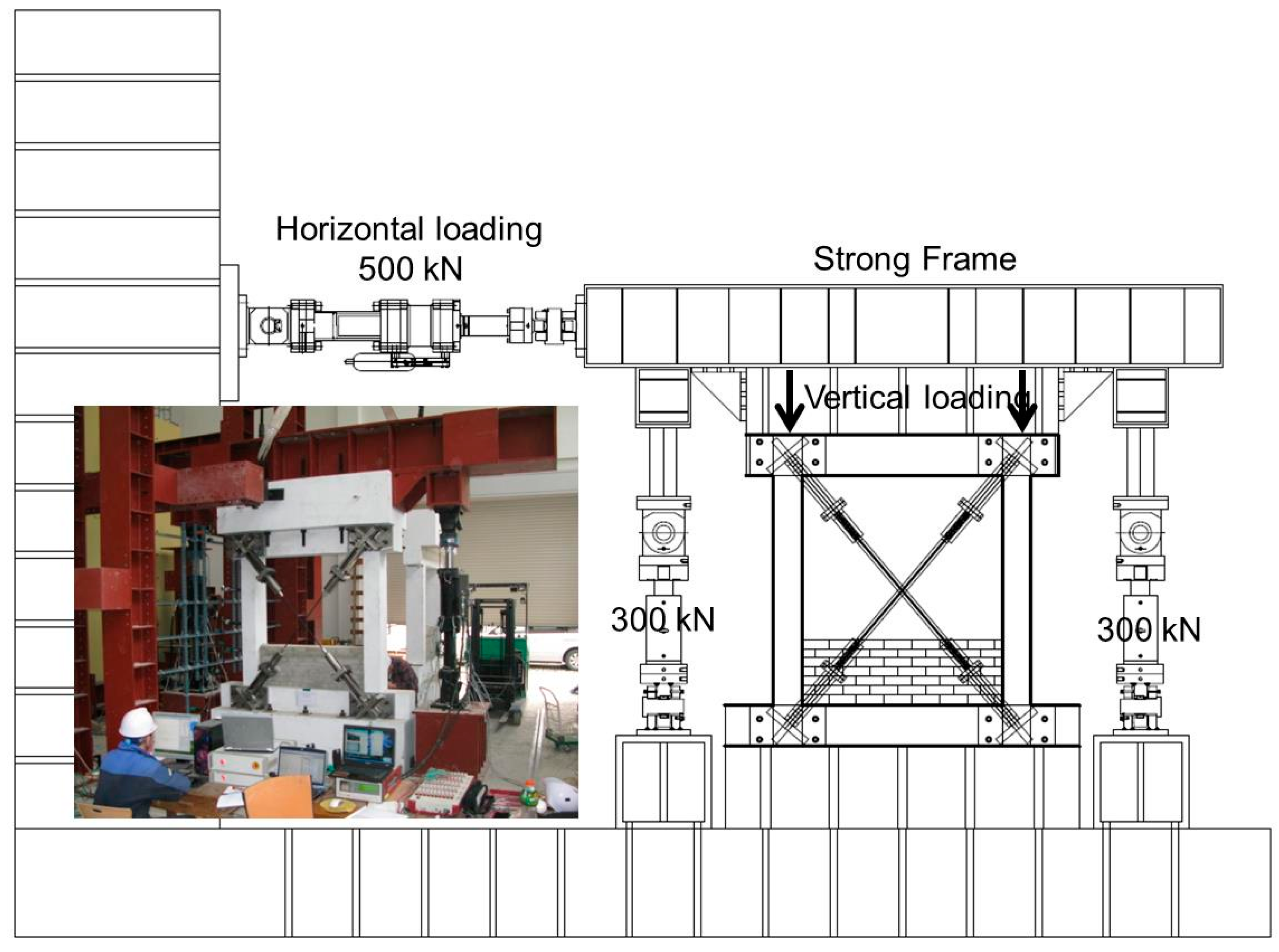
Figure 5 shows the test set-up for cyclic loading test. Loads were applied using two actuators with a capacity of 300 kN, and one actuator with a capacity of 500 kN. The two columns were subjected to a constant vertical load of 219 kN during cyclic lateral loading using the two 300-kN actuators. The cyclic lateral loading was controlled by the lateral displacement of the 500-kN actuator.
Figure 5.
Experimental configuration for the cyclic loading tests.
Figure 5.
Experimental configuration for the cyclic loading tests.
The load cycles were repeated three times at the lateral drift angles (R) of 0.08%, 0.1%, 0.12%, 0.15%, 0.2%, 0.25%, 0.31%, 0.4%, 0.49%, 0.62%, 0.79%, 1%, 1.24%, 1.54%, 2%, and 3.33%. Then, at each loading step, the lateral drift angle (R) was increased to approximately 1.2 times of the previous one, repeating the load cycle three times.
Table 4 lists the loading cycles applied to the each specimen.
Table 4.
The loading cycles used in the experiments.
Table 4.
The loading cycles used in the experiments.
| Loading step | 1 | 2 | 3 | 4 | 5 | 6 | 7 | 8 |
|---|
| Loading cycles | 1–3 | 4–6 | 7–9 | 10–12 | 13–15 | 16–18 | 19–21 | 22–24 |
| Drift angle R (%) | 0.08 | 0.1 | 0.12 | 0.15 | 0.2 | 0.25 | 0.31 | 0.4 |
| Lateral drift δ (mm) | 1.34 | 1.68 | 2.10 | 2.63 | 3.36 | 4.2 | 5.25 | 6.72 |
| Loading step | 9 | 10 | 11 | 12 | 13 | 14 | 15 | 16 |
| Loading cycles | 25–27 | 28–30 | 31–33 | 34–36 | 37–39 | 40–42 | 43–45 | 46–48 |
| Drift angle R (%) | 0.49 | 0.62 | 0.79 | 1 | 1.24 | 1.54 | 2 | 3.33 |
| Lateral drift δ (mm) | 8.4 | 10.5 | 13.4 | 16.8 | 21 | 26.3 | 33.6 | 56 |
4. Failure Sequence and Lateral Load–Drift Curves
For all specimens, the compressive behavior of the CFCC X-bracing was out-of-plane. This was originally expected to be compression-free, so that buckling failure of the braces would not occur. The behavior of the control and CFCC X-bracing strengthened specimens differed significantly. The flat plate-type and the protrusion-type specimens exhibited similar evidence of failure, with a similar crack appearance, and load–drift relations; however, the CFCC X-bracing specimens did not exhibit damage resulting from tensile stress. In the following discussion, we focus on the crack and failure patterns in terms of the lateral drift and load–drift relations during the final stages of the test. Each loading step was identical during the three loading cycles.
Table 5 lists the test results of the mechanical characterization following different loading steps, and
Table 6 lists the maximum shear strengths and drifts for the three specimens.
Table 5.
Results of the mechanical loading tests for the specimens.
Table 5.
Results of the mechanical loading tests for the specimens.
| Specimens | Load (kN) | Drift (mm) | Drift angle R (%) | Observation |
|---|
| RCFR | 37 | 2.6 | 0.15 | Flexural cracks |
| 68 | 5.3 | 0.31 | Shear cracks |
| −65 | −5.3 | 0.31 | Shear cracks |
| 96 | 10.5 | 0.62 | Shear cracks > 3 mm in width |
| 148 | 26.3 | 1.54 | Large shear cracks and peeling of concrete cover |
| 163 | 32.9 | 2.0 | Ultimate state |
| 99 | 44.0 | 2.6 | Shear collapse |
| CFCC-1 | 29 | 1.7 | 0.1 | Flexural cracks |
| 46 | 2.6 | 0.15 | Shear cracks |
| 263 | 33 | 1.96 | Ultimate state |
| −228 | 31.2 | 1.8 | Shear failure |
| CFCC-2 | −40 | 1.34 | 0.08 | Flexural cracks |
| 65 | 2.6 | 0.15 | Shear cracks |
| −293 | 32.3 | 1.92 | Ultimate state |
| −241 | 33 | 1.96 | Shear failure |
Table 6.
The maximum strengths and drifts of the specimens.
Table 6.
The maximum strengths and drifts of the specimens.
| Specimens | Positive | Negative | Final failure mode |
|---|
| Vmax a (kN) | δmax b (mm) | Vmax a (kN) | δmax b (mm) |
|---|
| RCFR | 163 | 32.9 | −160 | −33.6 | Shear failure and collapse of the columns |
| CFCC-1 | 263 | 33 | −257 | −26.2 | Shear failure of the columns |
| CFCC-2 | 275 | 31.2 | −293 | −32.3 | Shear failure of the columns |
4.1. Unbraced Control Specimen (RCFR)
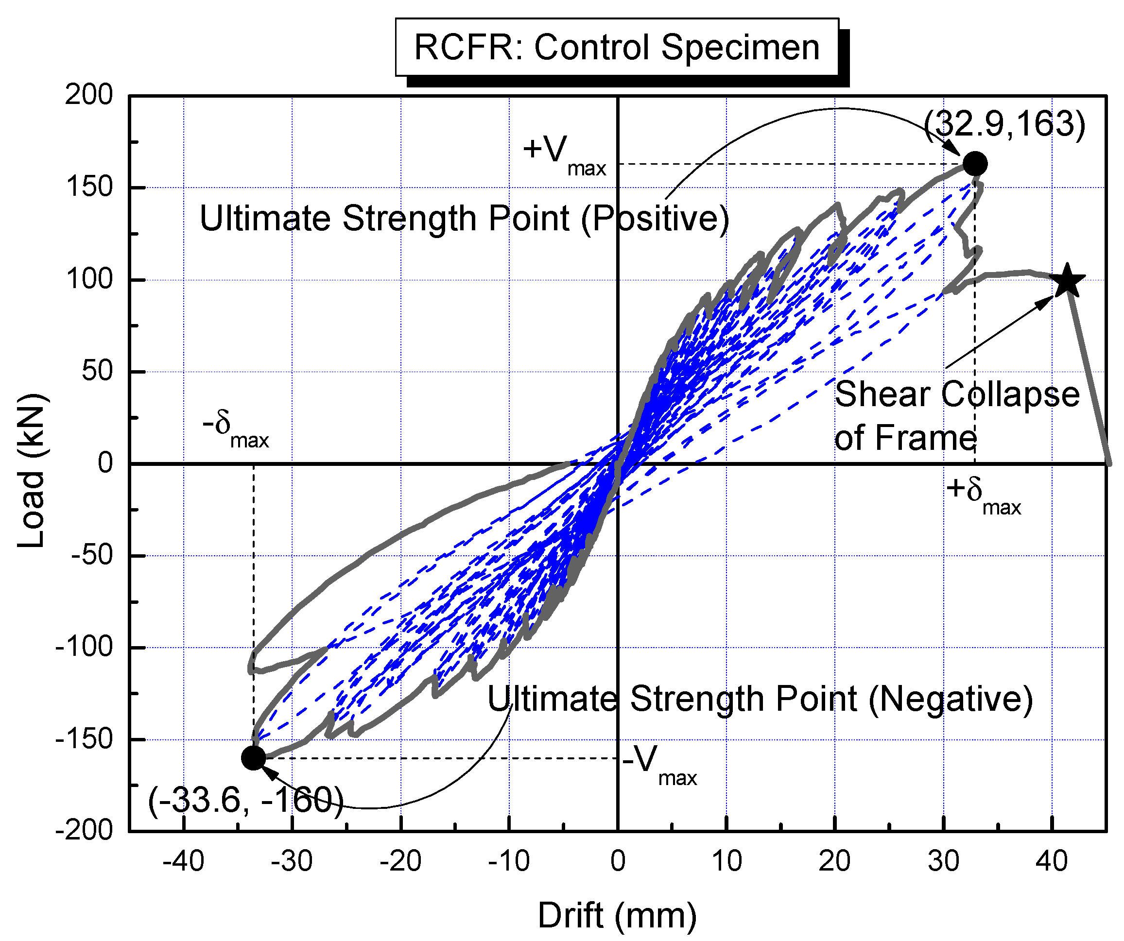
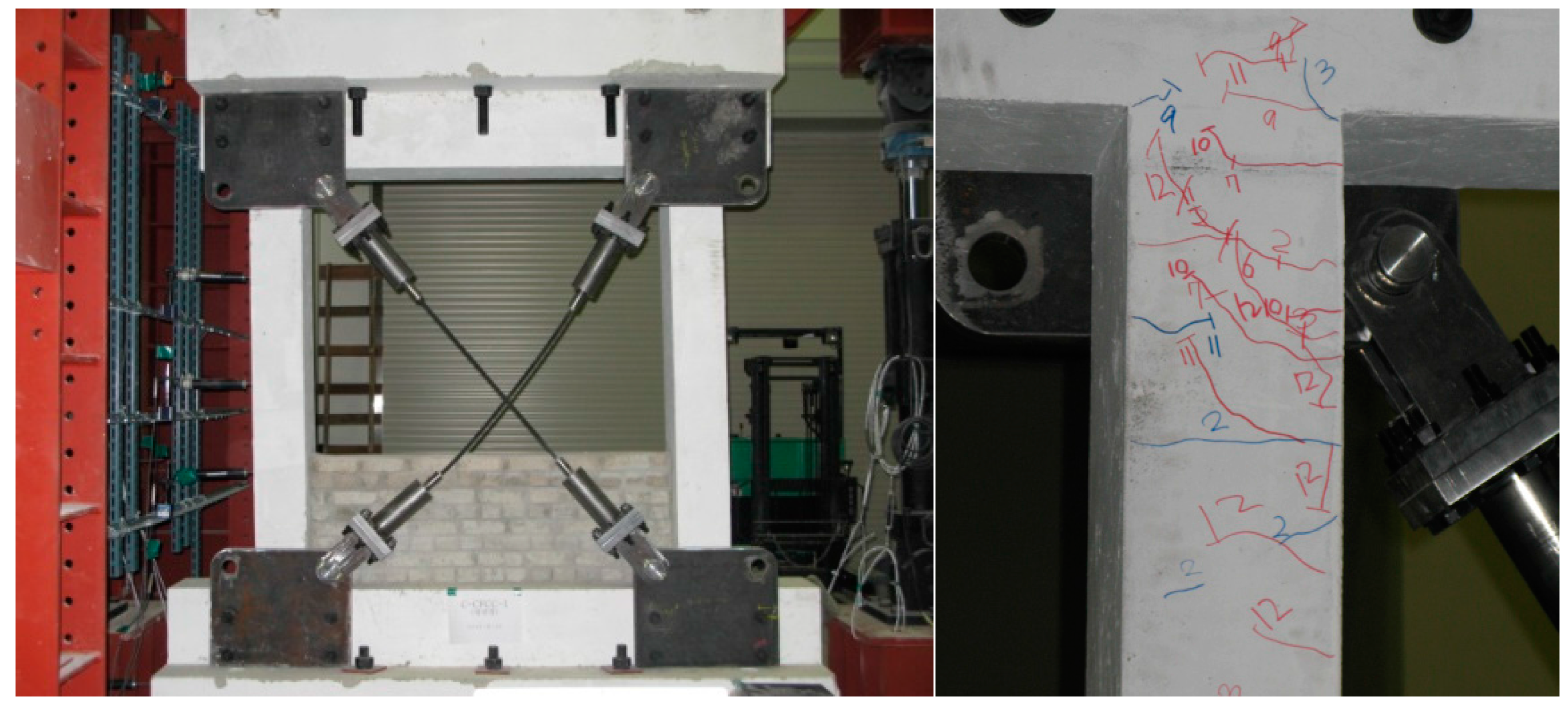
Figure 6 shows the RCFR specimen following the final cyclic load test, and
Figure 7 shows load–drift curves for the RCFR specimen. The first observed crack occurred at a positive load of 37 kN, and a small flexural crack appeared in the bottom column faces after three cycles at the fourth loading step (
R = 0.15%). Cracking was not observed in the center of the column. Flexural cracks extended into the middle of the column after step four. Following the seventh loading step (
R = 0.31%), with a load of both positive 68 kN and negative −65 kN, shear cracks were observed at the top faces of the columns, and a number of diagonal shear cracks appeared, some of which were more than 3 mm wide. When the applied load reached 148 kN, at the fourteenth positive loading step (
R = 1.54%), more large shear cracks were observed, with increased widths. We observed peeling failure due to shear forces from the concrete cover. This is likely to be the result of insufficient shear confinement.
Figure 6.
The RCFR specimen following the cyclic loading test.
Figure 6.
The RCFR specimen following the cyclic loading test.
Figure 7.
Load–drift relations for the RCFR sample.
Figure 7.
Load–drift relations for the RCFR sample.
Shear collapse occurred at the top of both columns following the application of a load of 99 kN, with a lateral drift of 44.0 mm (
R = 2.6%). The maximum load capacity of the frame of the RCFR specimen was a positive load of 163 kN, with a lateral drift of 32.9 mm (
R = 2.0%) (
Table 6). The maximum positive load capacity was similar to the maximum negative load capacity of 160 kN, with a lateral drift of 33.6 mm.
4.2. Flat-Plate Specimen (CFCC-1)
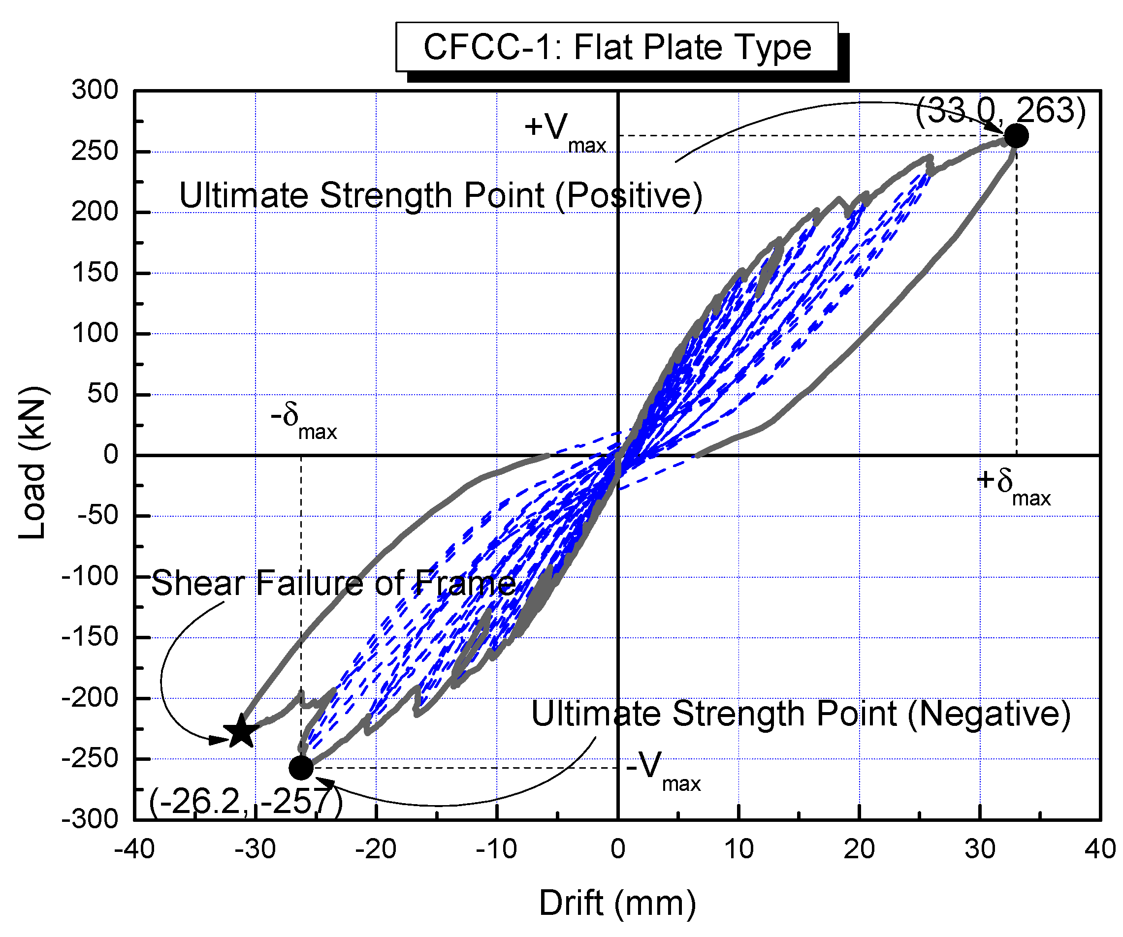
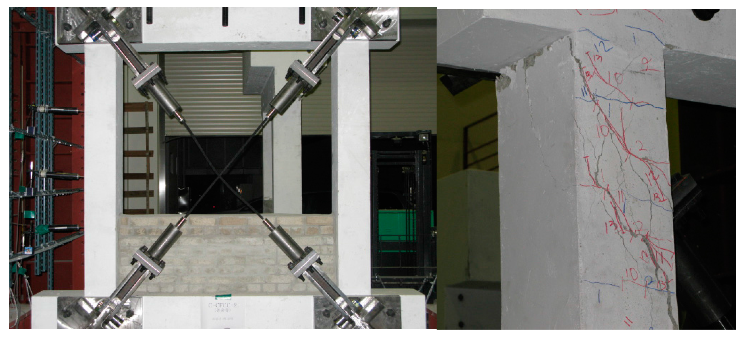
Figure 8 shows a photograph of the CFCC-1 specimen following the cyclic loading test, and
Figure 9 shows the load–drift curves. The CFCC-1 specimen had the flat-plate type X-bracing system (
Figure 3a). Cracks first appeared with a positive load of 29 kN, and a small flexural crack appeared in the top and bottom column faces following two cycles of the second loading step (
R = 0.1%). The flexural cracks increased in number and width, and shear cracks appeared following the fourth loading step (
R = 0.15%), with a positive load of 46 kN; these shear cracks extended into the middle of both columns. The maximum load capacity of the CFCC-1 specimen was a positive load of 263 kN, with a lateral drift of 33 mm (
R = 1.96%) (
Table 6 and
Figure 9). Shear failure occurred at the top and button of both columns under a negative load of 228 kN, with a lateral drift of 31.2 mm (
R = 1.8%), as shown in
Figure 9. It should be noted that buckling failure of the CFCC X-bracing was not observed. The CFCC X-bracing system for RC frames was therefore an effective reinforcement technique that can markedly increase the shear strength.
Figure 8.
The CFCC-1 specimen following the cyclic loading tests.
Figure 8.
The CFCC-1 specimen following the cyclic loading tests.
Figure 9.
Load–drift relations for sample CFCC-1.
Figure 9.
Load–drift relations for sample CFCC-1.
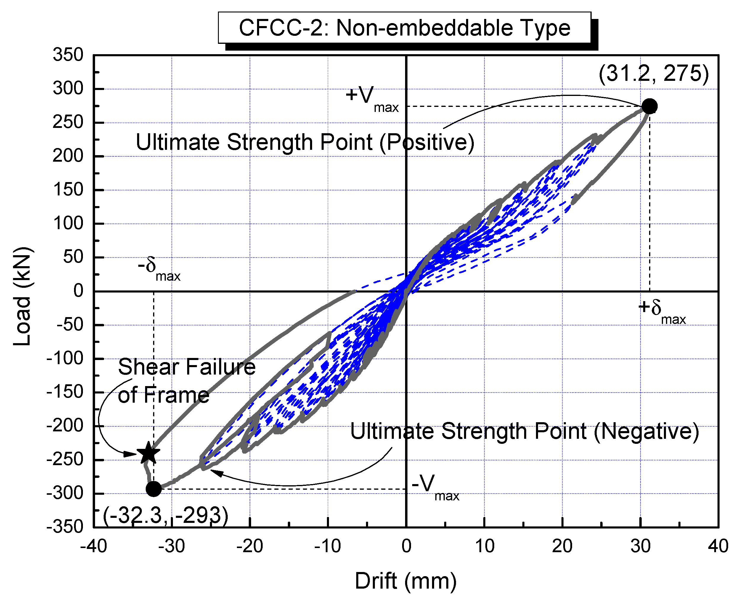
4.3. Protrusion-Type Specimen (CFCC-2)
Figure 10 shows a photograph of the CFCC-2 sample following the cyclic loading tests, and
Figure 11 shows load–drift curves. The CFCC-2 test specimen was reinforced using the protrusion-type X-bracing system, as shown in
Figure 3b. The first crack was observed with a negative load of −40 kN and with a lateral drift of 1.34 mm. This was a slight flexural crack, which appeared in the top and bottom of the column faces after three cycles of the first loading step (
R = 0.08%). Flexural cracks also appeared following the second and third loading steps, and shear cracks appeared following the fourth loading step (
R = 0.15%) with a positive load of 65 kN. The shear cracks increased in number and extended into the middle of both columns following the fourth loading step. Compared with the control specimen, however, there were a small number of cracks, which were less wide.
The maximum load capacity of specimen CFCC-2 was a negative load of −293 kN with a lateral drift of 32.3 mm (
R = 1.92%) (
Table 6 and
Figure 11), which is similar to specimen CFCC-1. Shear failure occurred at the top and bottom of both columns, and bucking failure was not observed.
Figure 10.
The CFCC-2 specimen following the cyclic load tests.
Figure 10.
The CFCC-2 specimen following the cyclic load tests.
Figure 11.
Load–drift relation for the CFCC-2 specimen.
Figure 11.
Load–drift relation for the CFCC-2 specimen.
5. Strength and Deformation
Figure 12 shows envelop curves of the lateral load–drift relations for the RCFR, CFCC-1 and CFCC-2 specimens. The larger of the maximum positive and negative load values were used here (see
Figure 7,
Figure 9 and
Figure 11).
Table 7 lists maximum strength and deformation capacities. The strength ratio (SR) is defined as the ratio of maximum load
Vmax of specimens with the CFCC X-bracing to that of the RCFR control specimen, and the drift ratio (DR) indicates the ratio of drift at the maximum point δ
max of the specimens with the CFCC X-bracing to that of the RCFR control specimen.
Figure 12.
The envelope of the load–drift relations of the three specimens.
Figure 12.
The envelope of the load–drift relations of the three specimens.
Table 7.
Summary of the strengths and deformation capacities.
Table 7.
Summary of the strengths and deformation capacities.
| Specimen | Maximum shear strength Vmax (kN) a | Drift at the maximum point δmax (mm) | Strength ratio (SR) b | Drift ratio (DR) c |
|---|
| RCFR | 163 | 32.9 | 1.00 (163/163) | 1.00 (32.9/32.9) |
| CFCC-1 | 263 (61.3%) | 33.0 | 1.61 (263/163) | 1.00 (33/32.9) |
| CFCC-2 | 293 (79.8%) | 32.3 | 1.80 (293/163) | 0.98 (32.3/32.9) |
The maximum shear strength of specimens CFCC-1 was 263 kN, and that of CFCC-2 was 293 kN; this represents an increase of a factor of approximately 1.6–1.8 (i.e., 60%–80%) larger than the RCFR control specimen (where the maximum shear strength was 163 kN). The drift ratio (DR) of the CFCC X-braced specimens was approximately 1.0, which means that the maximum drift was similar to that of the control RCFR specimen. This is because the failure modes of three specimens were similar; i.e., shear failure for the CFCC X-braced specimens and shear collapse of both columns for the RCFR control specimen.
The results of strength and deformation capacities mentioned above show that the CFCC X-bracing system for RC frames is an effective retrofitting technique to provide increased strength, which is the most promising approach for low- to medium-rise RC buildings. If the ductility is insufficient, an adequate strength can reduce the inelastic displacement [
27].
6. Conclusion
We have investigated the structural properties of CFCC X-bracing systems designed to improve the earthquake resistance of RC structures using cyclic loading tests. The CFCC X-bracing system proposed here has numerous advantages compared with conventional steel X-bracing systems, including an improved strength-to-weight ratio of the CFCC, compression-free bracing, and connection using bolt-nut joints, which can control the deflection of the X-bracing. These structural properties enable enhanced seismic resistance of RC frames. The results of this investigation can be summarized as follows.
The control RCFR specimen reached maximum load capacity at positive and negative loads of approximately 160 kN, with a lateral drift of 33 mm (R = 2.0%). Shear collapse occurred at the top of both columns under a load of 99 kN, with a lateral drift of 44.0 mm (R = 2.6%). The frame of a typical Korean RC school building was selected for designing the RCFR specimen, which represents a shear failure mode. The building was a three-story RC structure designed in the 1980s without seismic resistance features.
The maximum load capacity of specimen CFCC-1, which was reinforced with CFCC X-bracing with a flat plate-type configuration, was a positive load of 263 kN, with a lateral drift of 33 mm (R = 1.96%). The CFCC-2 specimen, with the protrusion-type X-bracing configuration exhibited a maximum strength with a negative load of −293 kN with a lateral drift of 32.3 mm (R = 1.92%), which is similar to that of specimen CFCC-1. Both of the CFCC X-braced system exhibited shear failure modes at the top and button of both columns, buckling failure of the bracing was not observed.
The strength capacity of both CFCC-1 and CFCC-2 specimens increased by a factor of approximately 1.7 compared with that of the RCFR control specimen. The deformation capacity of the CFCC X-braced specimens, however, was approximately equal to that of the RCFR control specimen. These strength and deformation capacities indicate that the CFCC X-bracing system is an effective retrofitting technique to provide increased strength. The reinforcement effect depends on the bracing material. It follows that the target strength capacity can be designed by choosing the appropriate CFCC X-bracing system.
This approach to seismic strengthening can eliminate the buckling failure modes of conventional steel X-bracing systems. However, further work is required to optimize the details of the connection between the CFCC bracing and the columns or beams, as well as to design the seismic retrofitting procedures for existing RC buildings.
This research was a preliminary approach regarding the use of new braces in carbon fibers and focused on an experimental investigation to study applicability of a new type of non-compression CFCC X-bracing system proposed in this study. As a recommendation for future work, however, additional theoretical and analytical studies are needed to justify the seismic behavior of the proposed CFCC X-bracing system.


