
Synthesis of Polyaniline (PANI) in Nano-Reaction Field of Cellulose Nanofiber (CNF), and Carbonization

Abstract
:
1. Introduction
2. Materials and Methods
2.1. Materials
2.2. Synthesis

| PANI/CNF | Aniline | Dried 1% CNF b | 1% CNF b suspension | 1% CNF b (EGUS) c | CNF/Aniline | Water | Product |
|---|---|---|---|---|---|---|---|
| (mg, mmol) a | (mg) | (mL) | (mg) | (Feed %) | (mL) | (mg) | |
| PA-NF1 | 99.7, 1.07 | 150.4 | – | – | 150.9 | 10 | 242.9 |
| PA-NF2 | 100.0, 1.07 | 99.8 | – | – | 99.8 | 10 | 194.7 |
| PA-NF3 | 100.1, 1.07 | 50.0 | – | – | 50.0 | 10 | 141.9 |
| PA-NF4 | 206.9, 2.22 | – | 20.0 | – | 96.7 | – | 302.0 |
| PA-NF5 | 209.3, 2.25 | – | 10.0 | – | 47.8 | 10 | 239.5 |
| PA-NF6 | 210.4, 2.26 | – | 50. | – | 23.7 | 15 | 249.9 |
| PA-NF7 | 200, 2.14 | – | 20 | – | 100 | – | 297.3 |
| PA-NF8 | 200, 2.14 | – | 20 | – | 100 | – | 314.7 |
| PA-NF9 | 200, 2.14 | – | – | 20 | 100 | 20 | 312.0 |
2.3. Techniques
3. Results and Discussion
3.1. IR


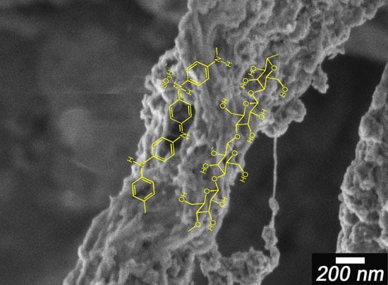
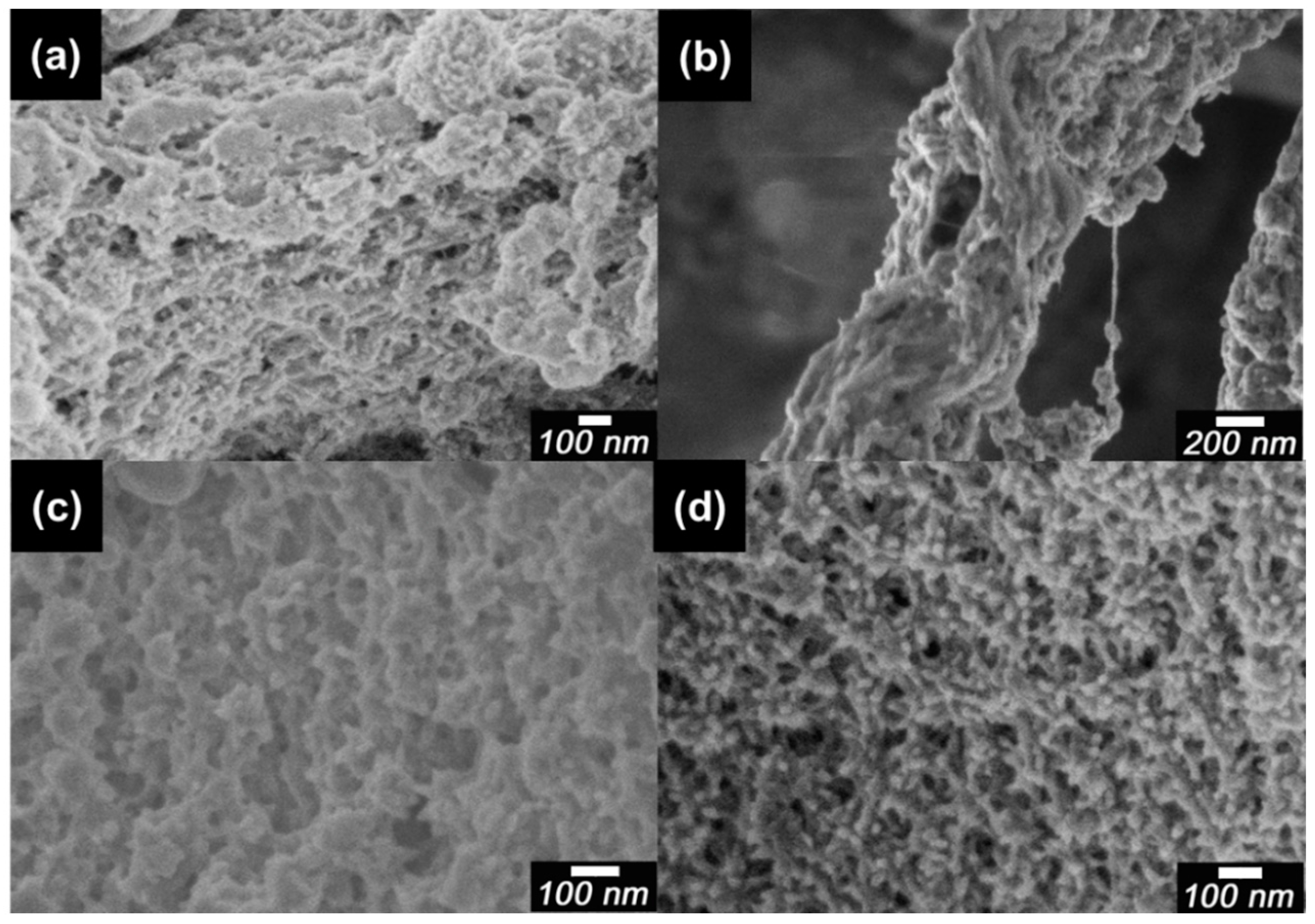
3.2. Morphology


3.3. ESR

| PANI/CNF | g-Value | ΔHpp (mT) | Ns (Spins/g) | I1/I2 a | σ (S/cm) |
|---|---|---|---|---|---|
| pure PANI | 2.00435 | 0.449 | 1.01×10²² | – | 1.26 × 10⁻¹ |
| PA-NF1 | 2.00375 | 0.410 | 5.39×10¹⁹ | – | 2.05 × 10⁻⁴ |
| PA-NF2 | 2.00355 | 0.410 | 6.90×10¹⁹ | – | 4.22 × 10⁻⁴ |
| PA-NF3 | 2.00354 | 0.410 | 7.83×10¹⁹ | – | 8.27 × 10⁻⁴ |
| PA-NF4 | 2.00357 | 0.410 | 5.38×10¹⁹ | – | 6.31 × 10⁻⁴ |
| PA-NF5 | 2.00346 | 0.410 | 7.31×10¹⁹ | – | 8.69 × 10⁻⁴ |
| PA-NF6 | 2.00351 | 0.410 | 7.01×10¹⁹ | – | 6.50 × 10⁻⁴ |
| PA-NF7 | 2.00412 | 0.620 | 7.32×10²¹ | 2.89 | 1.39 × 10⁻³ |
| PA-NF8 | 2.00429 | 0.620 | 7.36×10²¹ | 2.66 | 6.75 × 10⁻³ |
| PA-NF9 | 2.00422 | 0.567 | 7.83×10²¹ | 1.22 | 1.30 × 10⁻³ |

3.4. XRD


3.5. NMR
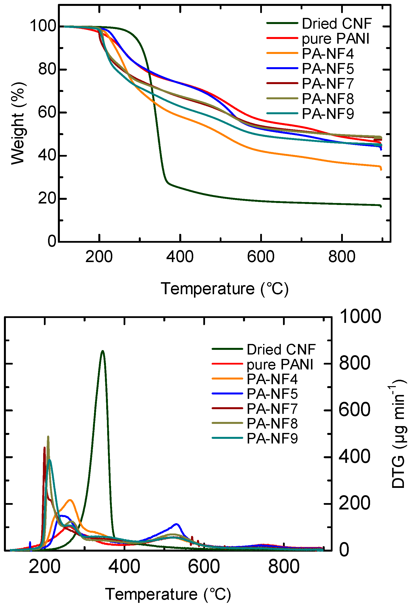
3.6. Thermal Property

| Entry | 5% Weight reduction temperature (°C) | Residue (%) |
|---|---|---|
| CNF | 289.0 | 20.0 |
| pure PANI | 223.5 | 48.0 |
| PA-NF4 | 224.2 | 36.6 |
| PA-NF5 | 235.9 | 44.8 |
| PA-NF7 | 201.2 | 48.4 |
| PA-NF8 | 208.9 | 48.8 |
| PA-NF9 | 206.8 | 45.7 |
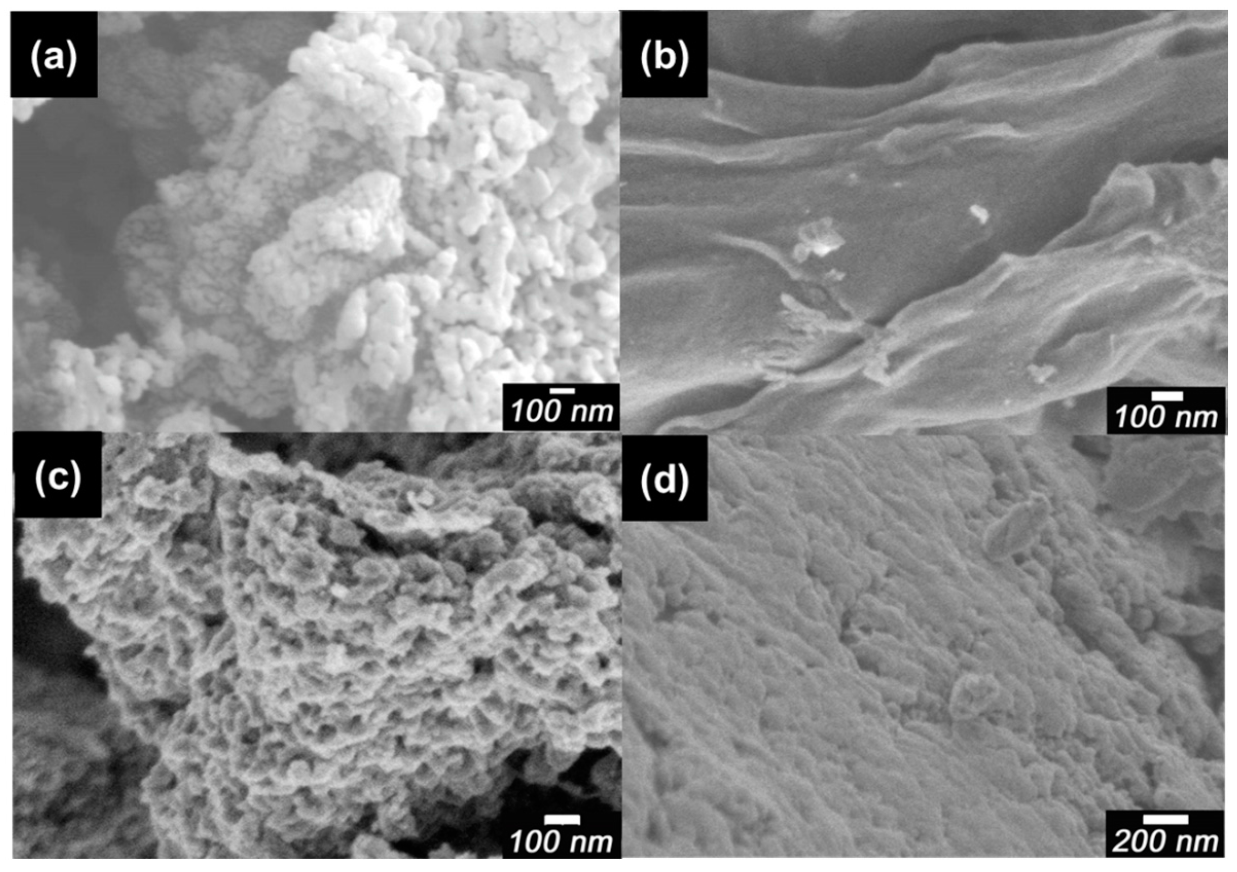
3.7. Shape Preserved Carbonization


4. Conclusions
Acknowledgments
Author Contributions
Conflicts of Interest
References
- Abe, K.; Iwamoto, S.; Yano, H. Obtaining cellulose nanofibers with a uniform width of 15 nm from wood. Biomacromolecules 2007, 8, 3276–3278. [Google Scholar] [CrossRef]
- Isogai, A.; Saito, T.; Fukuzumi, H. TEMPO-oxidized cellulose nanofibers. Nanoscale 2011, 3, 71–85. [Google Scholar] [CrossRef] [PubMed]
- Iwamoto, S.; Abe, K.; Yano, H. The effect of hemicelluloses on wood pulp nanofibrillation and nanofiber network characteristics. Biomacromolecules 2008, 9, 1022–1026. [Google Scholar] [CrossRef] [PubMed]
- Sossna, M.; Hollas, M.; Schaper, J.; Schaper, T. Structural development of asymmetric cellulose acetic microfiltration membranes prepared by a single-layer dry-casting method. J. Membr. Sci. 2007, 289, 7–14. [Google Scholar] [CrossRef]
- Nogi, M.; Iwamoto, S.; Nakagaito, A.N.; Yano, H. Optically transparent nanofiber paper. Adv. Mater. 2009, 21, 1595–1598. [Google Scholar] [CrossRef]
- Yano, H.; Sugiyama, J.; Nakagaito, A.N.; Nogi, M.; Matsuura, T.; Hikita, M.; Handa, K. Optically transparent composites reinforces with networks of bacterial nanofibers. Adv. Mater. 2005, 17, 153–155. [Google Scholar] [CrossRef]
- Iwamoto, S.; Nakagaito, A.N.; Yano, H.; Nogi, M. Optically transparent composites reinforced with plant fiber-based nanofibers. Appl. Phys. 2005, A81, 1109–1112. [Google Scholar] [CrossRef]
- Nogi, M.; Yano, H. Transparent nanocomposites based on cellulose produced by bacteria offer potential innovation in the electronics device industry. Adv. Mater. 2008, 20, 1849–1852. [Google Scholar] [CrossRef]
- Sehaqui, H.; Mushi, N.E.; Morimune, S.; Michaela Salajkova, M.; Nishino, T.; Berglund, L.A. Cellulose nanofiber orientation in nanopaper and nanocomposites by cold drawing. Appl. Mater. Interfaces 2012, 4, 1043–1049. [Google Scholar] [CrossRef]
- Jonoobi, M.; Harun, J.; Mathew, A.P.; Kristiina Oksman, K. Mechanical properties of cellulose nanofiber (CNF) reinforced polylactic acid (PLA) prepared by twin screw extrusion. Compos. Sci. Technol. 2010, 70, 1742–1747. [Google Scholar] [CrossRef]
- Siqueira, G.; Bras, J.; Dufresne, A. Cellulose whiskers versus microfibrils: Influence of the nature of the nanoparticle and its surface functionalization on the thermal and mechanical properties of nanocomposites. Biomacromolecules 2009, 10, 425–432. [Google Scholar] [CrossRef] [PubMed]
- Goto, H.; Yokoo, A. Polyaniline nanospheres synthesized in the presence of polyvinyl alcohol followed by preparation of carbon nanobeads structures. J. Dispers. Sci. Technol. 2013, 34, 406–410. [Google Scholar] [CrossRef]
- Oh, S.-Y.; Koh, H.C.; Choi, J.W.; Rhee, H.-W.; Kim, H.S. Preparation and properties of electrically conductive polyaniline-polystyrene composites by in-situ polymerization and blending. Polym. J. 1997, 29, 404–409. [Google Scholar] [CrossRef]
- Tahir, Z.M.; Alocilja, E.C.; Grooms, D.L. Polyaniline synthesis and its biosensor application. Biosens. Bioelectron. 2005, 20, 1690–1695. [Google Scholar] [CrossRef] [PubMed]
- Sadek, A.Z.; Wlodarski, W.; Shin, K.; Kaner, R.B.; Kalantar-zadeh, K. A polyaniline/WO3 nanofiber composite-based ZnO/64 YX LiNbO3SAW hydrogen gas sensor. Synth. Met. 2008, 158, 29–32. [Google Scholar] [CrossRef]
- Blanchet, G.B.; Loo, Y.-L.; Rogers, J.A.; Gao, F.; Fincher, C.R. Large area, high resolution, dry printing of conducting polymers for organic electronics. Appl. Phys. Lett. 2003, 82, 463–465. [Google Scholar] [CrossRef]
- Parthasarathy, R.V.; Martin, C.R. Template-synthesized polyaniline microtubules. Chem. Mater. 1994, 6, 1627–1632. [Google Scholar] [CrossRef]
- Pan, L.; Pu, L.; Shi, Y.; Song, S.; Xu, Z.; Zhang, R.; Youdou Zheng, Y. Synthesis of polyaniline nanotubes with a reactive template of manganese oxide. Adv. Mater. 2007, 19, 461–464. [Google Scholar] [CrossRef]
- Andreatta, A.; Cao, Y.; Chiang, J.C.; Heeger, A.J.; Smith, P. Electrically-conductive fibers of polyaniline spun from solutions in concentrated sulfuric acid. Synth. Met. 1988, 26, 383–389. [Google Scholar] [CrossRef]
- Hayashi, N. Production of cellulose nanofibers by using enzyme hydrolysis. Soc. Rubber Sci. Tech. Jpn. 2012, 85, 394. (In Japanese) [Google Scholar] [CrossRef]
- MacDiarmid, A.G.; Epstein, A.J. Secondary doping in polyaniline. Synth. Met. 1995, 69, 85–92. [Google Scholar] [CrossRef]
- Goto, H. Cholesteric liquid crystal inductive asymmetric polymerization: Synthesis of chiral polythiophene derivatives from achiral monomers in a cholesteric liquid crystal. Macromolecules 2007, 40, 1377–1385. [Google Scholar] [CrossRef]
- Goto, H. Doping-dedoping-driven optic effect of π-conjugated polymers prepared in cholesteric-liquid-crystal electrolytes. Phys. Rev. Letts. 2007, 98, 253901. [Google Scholar] [CrossRef] [PubMed]
- Goto, H. Asymmetric polymerisation in liquid crystals and resultant electro-chiroptical effect: Structure organizing polymerisation and chiral charge carrier “chiralion”. IOP Conf. Ser. Mater. Sci. Eng. 2014, 012013. [Google Scholar] [CrossRef]
- Wulff, G.; Gross, T.; Schönfeld, R. Enzyme models based on molecularly imprinted polymers with strong esterase activity. Angew. Chem. 1997, 36, 1961–1964. [Google Scholar] [CrossRef]
© 2016 by the authors. Licensee MDPI, Basel, Switzerland. This article is an open access article distributed under the terms and conditions of the Creative Commons by Attribution (CC-BY) license ( http://creativecommons.org/licenses/by/4.0/).
Share and Cite
Kaitsuka, Y.; Hayashi, N.; Shimokawa, T.; Togawa, E.; Goto, H. Synthesis of Polyaniline (PANI) in Nano-Reaction Field of Cellulose Nanofiber (CNF), and Carbonization. Polymers 2016, 8, 40. https://doi.org/10.3390/polym8020040
Kaitsuka Y, Hayashi N, Shimokawa T, Togawa E, Goto H. Synthesis of Polyaniline (PANI) in Nano-Reaction Field of Cellulose Nanofiber (CNF), and Carbonization. Polymers. 2016; 8(2):40. https://doi.org/10.3390/polym8020040
Chicago/Turabian StyleKaitsuka, Yuki, Noriko Hayashi, Tomoko Shimokawa, Eiji Togawa, and Hiromasa Goto. 2016. "Synthesis of Polyaniline (PANI) in Nano-Reaction Field of Cellulose Nanofiber (CNF), and Carbonization" Polymers 8, no. 2: 40. https://doi.org/10.3390/polym8020040