A New Technique for Improved Use of Thermal Energy from Waste Effluents


1
Escuela Politécnica Superior de Ingeniería, Universidad de Santiago de Compostela, Campus Universitario, 27002-Lugo, Spain
2
Facultad de Informática, Universidad de La Coruña, 15001 A Coruña, Spain
*
Authors to whom correspondence should be addressed.
Agronomy 2020, 10(1), 97; https://doi.org/10.3390/agronomy10010097
Submission received: 3 December 2019
/
Revised: 6 January 2020
/
Accepted: 7 January 2020
/
Published: 9 January 2020
(This article belongs to the Special Issue Selected Papers from 10th Iberian Agroengineering Congress)
Abstract
:Energy sustainability and environmental protection in general are at the heart of engineering and industry discussions. Countless efforts have been devoted to improving the energy efficiency of industrial processes and specifically to harnessing their waste energy sources. One such source is waste from agro-industrial processes, which is frequently characterized by increased temperatures and high polluting potential. There are multiple available choices for exploiting energy from such waste, but this paper proposes a new alternative technique that substantially improves the efficiency. Based on the technology of leveraging a hot liquid effluent for heating a process fluid, this system introduces a third liquid to be revalorized by drying that is placed in between the hot and cold liquids. By adding stirrers inside the heat exchanger, the thermal resistance of the third fluid is reduced to a negligible level. Thus, this system has almost the same advantages as the previous one, but with the added benefit that it allows drying of a third fluid. One of the specific applications of this proposed technology is using heat from waste effluents to obtain dried food products. In the present work, it was used to dry slaughterhouse blood to obtain so-called “blood meal”, a product with a high added value that is used as pet food or organic fertilizer, and also has many other industrial applications. As shown here, the new technique outperforms existing alternatives in terms of energy efficiency and economic profitability.
Keywords:
residual energy; valorization; drying; vacuum; multiple-effect evaporation; blood; blood meal; slaughterhouse1. Introduction
Energy efficiency of industrial processes is a major issue due to its economic and environmental implications. Energy efficiency can be achieved through the use of energy from residual effluents, such as those of agroindustry, which are often characterized by high temperatures. Energy contained in waste effluents can be extracted with a number of techniques of the chemical or thermal type. Chemical techniques use effluents to extract substances with a high value such as fuel gas (biogas, biosolids, syngas, and bio-oil), whereas thermal techniques involve heat transfer from effluents to a cold fluid. The former is more commonly used with highly dirty, sludge-type effluents, whereas the latter are preferentially applied to cleaner, more dilute effluents but can also be used with sludge [1].
Thermal techniques for energy extraction differ depending on the temperature of the effluent to be processed. We deemed temperatures below 80 °C to be low and temperatures above this level to be high. Temperatures around this value strongly influence the design of thermal recovery equipment [2]. Most recovery techniques, however, have been designed for operation at high temperatures.
Effluents at temperatures higher than 80 °C are very easy to valorize and easily have an industrial application [2]. One immediate use of effluents is as heating fluids for conditioning of dwellings and thermal comfort. An urban application is thermal recovery from hot household wastewater [3], using heat exchangers to deliver recovered heat in the form of heating to households. One other highly interesting use is for heating animal farms, such as pig farms, which can benefit from radiant floor heating provided by agrarian waste effluents [4].
One other use of effluents is for generating electricity by means of devices based on organic Rankine or Kalina cycles, in which the alternative evaporation and condensation of fluids result in the movement of a mechanical shaft connected to an electric generator. Rankine and Kalina cycles provide energy as electrical power without releasing toxic gases, albeit at the expense of very low yields and high operating temperatures [5]. These shortcomings make them useless in many cases.
One widespread choice for the efficient exploitation of thermal energy from waste effluents is heating cold fluids prior to entering an industrial process. Unlike the Rankine and Kalina cycles, this approach allows energy to be recovered from effluents at temperatures well below 70 °C [5]. Process fluids are usually fed at room temperature or slightly low (10–25 °C) [6] and require large amounts of energy to be heated. It can be obtained free from hot waste effluents. This is an advantageous alternative to the Rankine cycle, even when fluids are to be heated by a few degrees only.
Heat-pump technology allows effluents at temperatures as low as 15 °C to be highly efficiently used and has been deemed the best choice for processing cooled effluents [7]. A heat pump consists of a closed circuit where a cooling fluid continuously evaporates and condenses at a pair of heat exchangers [2]. It uses a compressor and operates like a refrigerator, albeit in the opposite direction. Heat pumps are the most efficient machines; a pump fed with wastewater at about 15 °C can easily provide a coefficient of performance (COP) exceeding 3.5 (i.e., the pump will provide 3.5 units of energy for each unit it receives). A heat pump uses energy mainly to operate the compressor. Thus, a compressor using 10 kW of electric power will allow a pump to deliver 35 kW in the form of heat. The temperature of household wastewater typically ranges from 10 to 25 °C, depending on the time of year [6]. Because this type of waste is produced massively and expected to increase in the future, it provides a major energy niche that could be highly efficiently exploited with heat pumps.
A need clearly exists for further development of techniques enabling the efficient extraction of energy from waste effluents—particularly low-temperature effluents, which account for 66% of all industrial effluents produced on a global scale [7]. The amount of thermal energy released in wastewater by a city of average size could meet about 7% of its energy demand in the form of heating and hot water [3]. A number of researchers have concluded that the typical improvement schemes for wastewater treatment plants are largely inefficient and should be supplemented with better exploitation of thermal energy [8]. In fact, a typical treatment plant can easily produce 35 m3 of biogas per inhabitant per day [9] but can only extract 10%–14% of the chemical energy contained in the effluents [8]. Unlike thermal recovery technology (particularly that of heat pumps), wastewater treatment plants hardly achieve energy surpluses.
In this work, a novel technique for improving the efficiency with which energy can be extracted from waste effluents was developed. Operationally, it involves transferring energy from waste effluents to process fluids to be preheated; however, one or more vacuum chambers are placed between the hot and cold spots, to boil a fluid to be revalorized by dehydration. This generates a twofold benefit, as it allows a process fluid to be preheated and a third fluid or raw material, such as milk, brine, juice, or blood, to be dried. This new technique can be of especial interest to agri-food industries, which usually handle liquid products to be revalorized by drying, either by removing most of the moisture they contain or only part of it, to reduce its fluidity and obtain a concentrate [10]. One potential use of great economic interest is drying slaughterhouse blood to obtain blood meal, a product with a moisture content of 8%–12% and a high market value. Blood meal has a number of industrial uses [11], including the production of pet food, organic fertilizers, gas-proof filters, asphaltic emulsions, cosmetics, vaccines, bakery products, chemicals, and pharmaceuticals.
2. Material and Methods
2.1. Layout of the Proposed Technique: Heating of a Processed Fluid by Means of a Waste Effluent and an Interposed Third Fluid
The proposed technique is based on existing systems for using energy extracted from waste effluents (such as cleaning wastewater or sewage water) to preheat industrial process fluids (as boiler feed water or supply water used for cleaning). As can be seen in Figure 1, the process fluid and the waste effluent are isolated by a metal plate (1), across which heat is transferred from the former to the latter. Heat travels through three thermal resistances, namely (3) the boundary layer of the hot fluid (3), the thickness of the metal plate (1), and the boundary layer of the cold fluid (6). The boundary layers are thin fluid films that stick virtually statically to the metal plate by effect of viscosity [12]. Heat transfer across the boundaries is much more difficult than in the remainder of the fluid, so the thicker a boundary layer is, the higher its resistance to heat transfer will be [13].
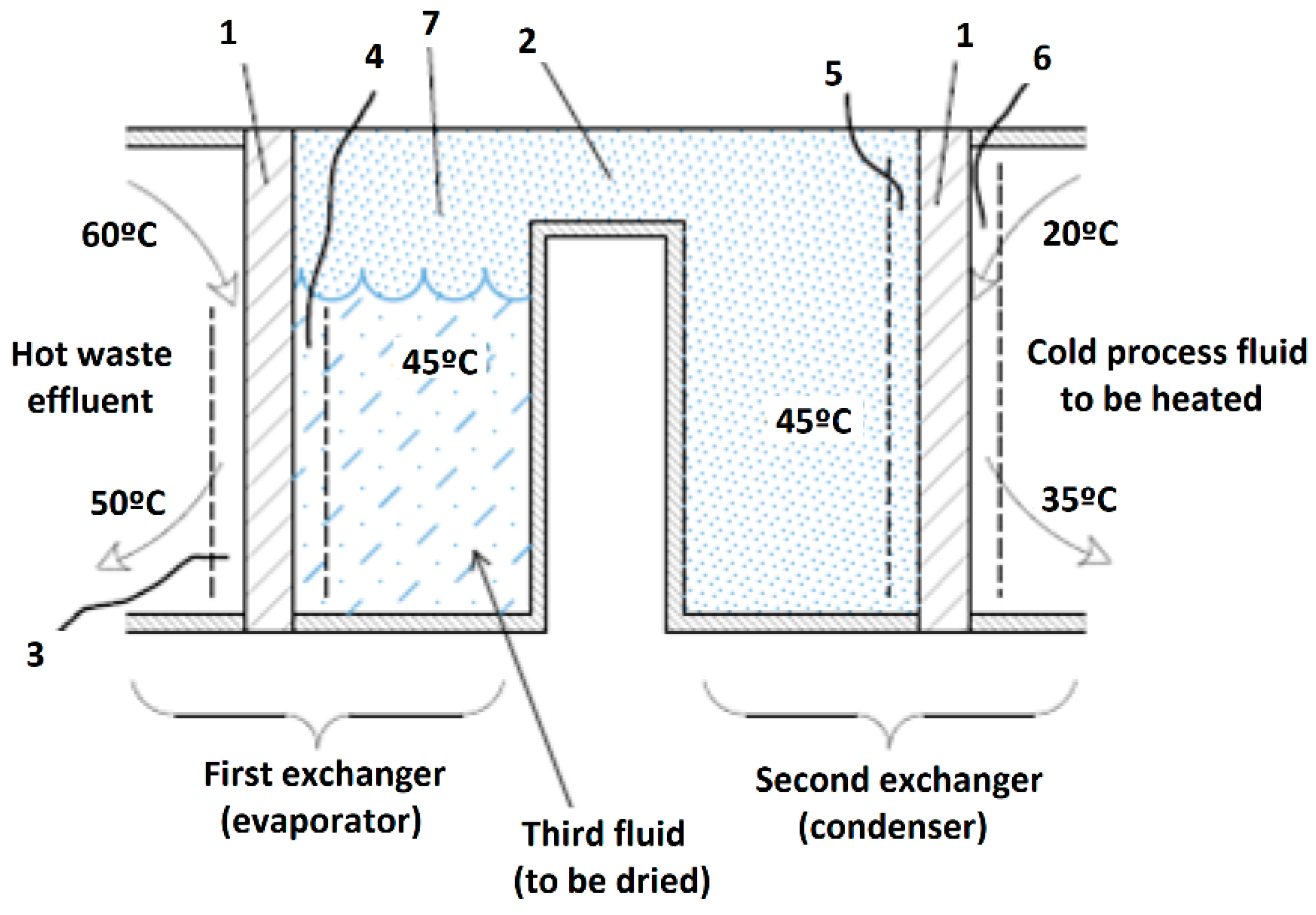
The main novelty is placing a liquid product (third fluid) to be dried in between the waste effluent (hot spot) and the fluid to be preheated (cold spot). The fluid is dried under vacuum-boiling, and two heat exchangers are used for this purpose (Figure 2). In this way, the third fluid is evaporated in a boiling chamber under vacuum (7) and condensed on the walls of the second exchanger, to obtain a condensate layer (5). This system presents 6 serially arranged thermal resistances rather than 3 of the previous one. Such resistances are as follows: the boundary layer of the waste effluent (3), the thickness of the metal plate (1) in the first exchanger, the boundary layer of the third fluid (4) in the first exchanger, the vapor condensate layer (5) in the second exchanger, the thickness of the metal plate (1) in the second exchanger, and the boundary layer of the cold fluid (6) passing through it.
The drawback of presenting so many resistances can be avoided by stirring in both exchangers. The stirrers to be used should scrub the metal plates (1) in order to mechanically break the boundary layers of the waste effluent in the first exchanger (4) and the condensate layer in the second (5). Heat transfer in the continuously broken boundary layers is governed by conduction in a no-steady state. This results in very high heat-transfer coefficients and hence in negligible thermal resistance. Figure 3 shows a three-dimensional view of a heat exchanger with stirrers. For operational reasons, stirrers are only placed in the bulk of the third fluid; however, they might also be placed in the waste effluent and process fluid.
Breaking the boundary layers allows the number of resistances to be reduced from 6 to 4, which is close to the 3 of the system with no intermediate fluid. Both systems include the resistances of the boundary layers of the hot (3) and cold fluid (6), and the metal plate or plates (1)—two for this system and a single one for the previous approach. However, the resistance of the fluid boundary layers in thermal-transfer processes is usually much higher than that of the metal plates [10]. Consequently, thermal resistance is similar in both systems (with or without a third fluid).
The vacuum in the boiling chamber (7) is maintained by effect of vapor condensation in the second exchanger and the aid of a vacuum pump. No pump is needed in the ideal situation because condensing the gas present in an airtight chamber reduces the inner pressure [13]. In industrial practice, however, all boiling substances release some noncondensing gas at the usual operating temperatures [12]. Therefore, the condenser must be supplemented with a vacuum pump, to withdraw uncondensed gases [10]. One disadvantage of using a vacuum pump is that it also withdraws some water vapor and results in a proportional loss of its condensation energy in the second exchanger [14]. By identifying where uncondensed products accumulate in the boiling chamber (7) and placing the pump suction there, we can typically reduce the energy loss to 10% [10].
The situation where the temperature of the hot fluid is below the threshold for effective application of the proposed technique poses special problems. However, fluids can still be exploited by using heat-pump technology. Thus, a cooling fluid is pumped through a closed circuit, where it undergoes successive evaporation and condensation in order to facilitate absorption of thermal energy from a cool fluid and release at a point where the temperature exceeds that of the fluid [12].
To improve its efficiency, the proposed system can be modified by splitting the evaporation chamber into a number of serially connected chambers to form a multiple-effect evaporator [10]. This substantially increases energy savings because the energy needed to evaporate a given amount of water is being reduced in proportion to the number of serial evaporators used [14]. Thus, using two multi-effect evaporators can reduce evaporation costs by one-half, and using three by two-thirds [10]. In order to enable thermal exchange between each evaporator and the next, their boiling temperatures must be made different by evacuating them to a different extent. The boiling temperature at each evaporator in a typical three-evaporator system could be 55, 45, and 35 °C, respectively, the respective pressures also being obviously different and decreasing with decreasing temperature [12].
Figure 4 shows a flowchart of the system, including two exchangers and three serially arranged evaporators. Each evaporator comprises an internal chamber for condensation and an external chamber for boiling the product to be dried or concentrated. Each circuit is depicted in a different color: red for the third fluid to be dried (slaughterhouse blood); dark blue for the water vapor released by boiling blood; light blue for the cold supply water to be heated (cold spot); brown for the hot waste effluent; green for the heat pump (which is required because the effluent can enter the system at as low a temperature as 45 °C); and black for drained condensates and withdrawn noncondensing gases. The pump recycles cooling fluid R-134a, which is evaporated at 10 °C by absorbing energy from the effluent in the first heat exchanger; then its pressure is raised by a compressor to facilitate condensation at 45 °C in the first evaporator.
2.2. Description of a Prototype Apparatus
To test and validate the proposed technology, a functional prototype was built whose main components were a proprietary design custom vertical plate heat exchanger (referred to as first exchanger), a gravimetric decanter, a condenser (referred to as second exchanger), and a vacuum pump. The gravimetric decanter is a device interposed between the first and second exchanger; its purpose is so separate gases from liquid particles. Inside the first exchanger, blood is boiling under vacuum conditions at a temperature not higher than 43 °C. This boiling constitutes a dewatering process that turns liquid blood into blood meal. The boiling generates water vapor, which leaves the first exchanger, goes through the gravimetric decanter, and finally reaches the second exchanger, where it condensates into liquid water. If the decanter were suppressed, the vapor would drag little blood particles upward and would lead them up to the condenser. That would have a devastating effect, since it means losing product. Blood must remain inside the first exchanger in order to be transformed into blood meal.
The vertical plate heat exchanger consists of three cylindrical chambers of nominal diameter DN500 (508 mm outer diameter and 495.2 mm inner diameter), hermetically separated. The plates between chambers (in other words, the heat-exchange surfaces), are 6 mm thick. The central chamber, which is 50 mm thick, is intended for the fluid to be dehydrated, which is manually fed. Both side chambers, each one 35 mm thick, receive the hot residual effluent through a pipe of nominal diameter DN15, which is pumped with a variable flow of 500–1600 L h−1, providing an internal pressure in the side chambers of +0.6 bar. Inside the central chamber, there is a 4-blade stirrer that reaches the full volume of the chamber to scrub the walls. It is moved by a central axle driven by a 0.75 kW external motor, which can rotate at variable speed between 0 and 240 rpm.
The one-step condenser is a shell-and-tube type, 2 m long, and vertically arranged. It consists of 9 tubes with internal baffles every 1/5 of diameter. In the gas outlet to the condenser, there is the gravimetric decanter.
The liquid ring vacuum pump is equipped with a 4-kW engine, and its nominal flow is 120 m3 h−1. It is connected to the central chamber of the heat exchanger, providing a vacuum ranging from −0.8 to −0.94 bars
2.3. Heat Exchanger Performance
The measurement of heat-recovery efficiency was made by calculating the overall heat-transfer coefficient in relation to the rotation speed of the heat-exchanger stirrer, as it is the most conditioning variable due to the breaking of the boundary layers. Twenty minutes of testing was conducted, varying the rotation speed between 0 and 100 rpm, with three repetitions per condition.
The two side chambers of the heat exchanger were fed a flow rate of 1500 L h−1 of hot water. The input temperature was 63–80 °C, and the output temperature was 74–58 °C. In the vacuum chamber, 9 L of water was introduced and subjected to a vacuum of −0.91 bar. At the end of each test, the evaporated amount was measured and the transferred heat (Q) was calculated, taking into account the latent heat of vaporization.
The overall heat-transfer coefficient was calculated with Equation (1):
where U is the overall heat-transfer coefficient (with units of W m−2 K−1), Q is the energy recovered per unit time, A is the heat-exchange surface (0.385 m2, taking into account the two exchange plates of the prototype), and ΔTml is the logarithmic mean temperature difference, according to Equation (2):
where ΔTb is the thermal gap between the hot waste effluent at the inlet and the boiling blood, and ΔTa is the thermal gap between the hot waste effluent at the outlet and the boiling blood.
Another expression (3) for the overall heat-transfer coefficient was also employed, the one that takes into account the local heat-transfer coefficients. They are named as h3, h1, and h2 and represent a local heat-transfer coefficient through the metallic wall (h3) and through the boundary layers on both its sides (h1 and h2). Units are the same as their overall counterpart. The expression based on the hi is as follows:
where the local coefficient h2 cannot be improved at all, unless the metallic wall is thinned, and the other two can be improved via higher flow rates of higher rotational speed. For the calculation of h2, since it is due to the thermal conduction in a metallic surface, the following expression (4) is used:
where k is the thermal conductivity (14 W m−1 K−1 for stainless steel), and t is the wall thickness (in this experiment 6 mm).
2.4. Drying Blood into Blood Meal
The prototype was tested for drying blood (third fluid), to obtain blood meal in real conditions in a slaughterhouse near Lugo city (NW Spain), where cows are slaughtered daily (about 25,000 heads a year). Gut-washing requires water over 80 °C, so supply water is heated in a boiler. The hot waste effluent resulting from this washing is discarded directly to a wastewater treatment plant. Blood is delivered to a waste manager who disposes of it, at a cost to the slaughterhouse.
The prototype was installed in the facility. For the experiments, blood was obtained manually from the slaughtered animals by using a vampire knife; the blood was collected in a drum and used immediately, to prevent clotting. It was manually fed into the heat exchanger, filling the total volume of 9 L of the boiling chamber. A vacuum of −0.91 bar was applied, corresponding to a blood boiling temperature of 43.4 °C.
The heat exchanger was fed with washing wastewater previously filtered (hot waste effluent). It was used 550–800 L h−1 of effluent at a variable temperature between 60 and 80 °C. Supply water for the washing (process fluid) was preheated, which entered at 10–15 °C, with a flow rate of 1500–2000 L h−1. The average thermal gap between the hot effluent and the boiling temperature of the blood was 31.6 °C.
The inner stirrer of the heat exchanger rotated at 60 revolutions per minute (rpm), for about 75% of the time, while the remaining 25% had to be lowered to 15 rpm, so as not to overload the engine when the liquid became sludge. The treatment was maintained until the blood meal was obtained, when the sludge was disaggregated. The time required was around 1 h, depending on the working conditions. Finally, the amount of blood meal obtained was weighed and later its moisture content was determined in laboratory by oven drying at 105 °C to a constant weight.
2.5. Economic Feasibility
One key factor that determines economic feasibility is how much heat can be extracted from the hot waste effluent. In other words, the maximum temperature drops attainable with some technology. If the waste effluent comes with 80 °C, and technology A is capable of cooling it down to 20 °C, is extracting more energy and being more profitable than technology B that only decreases temperature to 40 °C.
The 40 °C example is feasible when heating dwellings or preheating process fluids, but to achieve further cooling (for example, 20 °C), a heat pump is usually needed. This is because the pump, working with the R134a coolant, can sustain a constant boiling temperature of no more than 10 °C in its evaporator, which makes heat transfer from a source at 20 °C possible. On the other hand, a dwelling will heat up to temperatures much higher than 10 °C.
To calculate the energy savings, an effluent at 80 °C was considered to be cooled to the minimum usable by the technology (20 °C if it includes heat pump, 40 °C if not). It was assumed that, in all cases, 90% of the energy ceded by water is recovered, which is valued as the equivalent amount of diesel heating oil. For the calculations, the energy density of the diesel fuel was considered 32.93 MJ L−1, and its market price 0.7 € L−1. To know the amount of blood meal obtained per ton of waste effluent under some cooling range, the ratio of blood meal per ton of raw blood must be taken into consideration. From our experiments, that ratio is 15%. The first step is to assess the amount of raw blood that is possible to dry with the energy extracted from the heat waste effluent. For that purpose, the extracted energy is divided by the blood latent heat of vaporization at −0.9 bar, 2.39 MJ kg−1. The resulting weight is multiplied by 15/85 to obtain the mass of blood meal.
For the economic valorization, it was supposed blood meal under the assumption of a market price of 400 € t−1 and a production cost of 287 € t−1 with a single evaporator and 115 € t−1 with three.
3. Results
3.1. Heat Exchanger Performance
The most interesting property of the heat exchanger is the dependence of its performance with respect to the degree of stirrer movement, measured in rpm. The performance has the unit of W/(m2·K), meaning the amount of heat that enters the exchanger per second, square meter of exchange surface, and Kelvin degree of thermal difference.
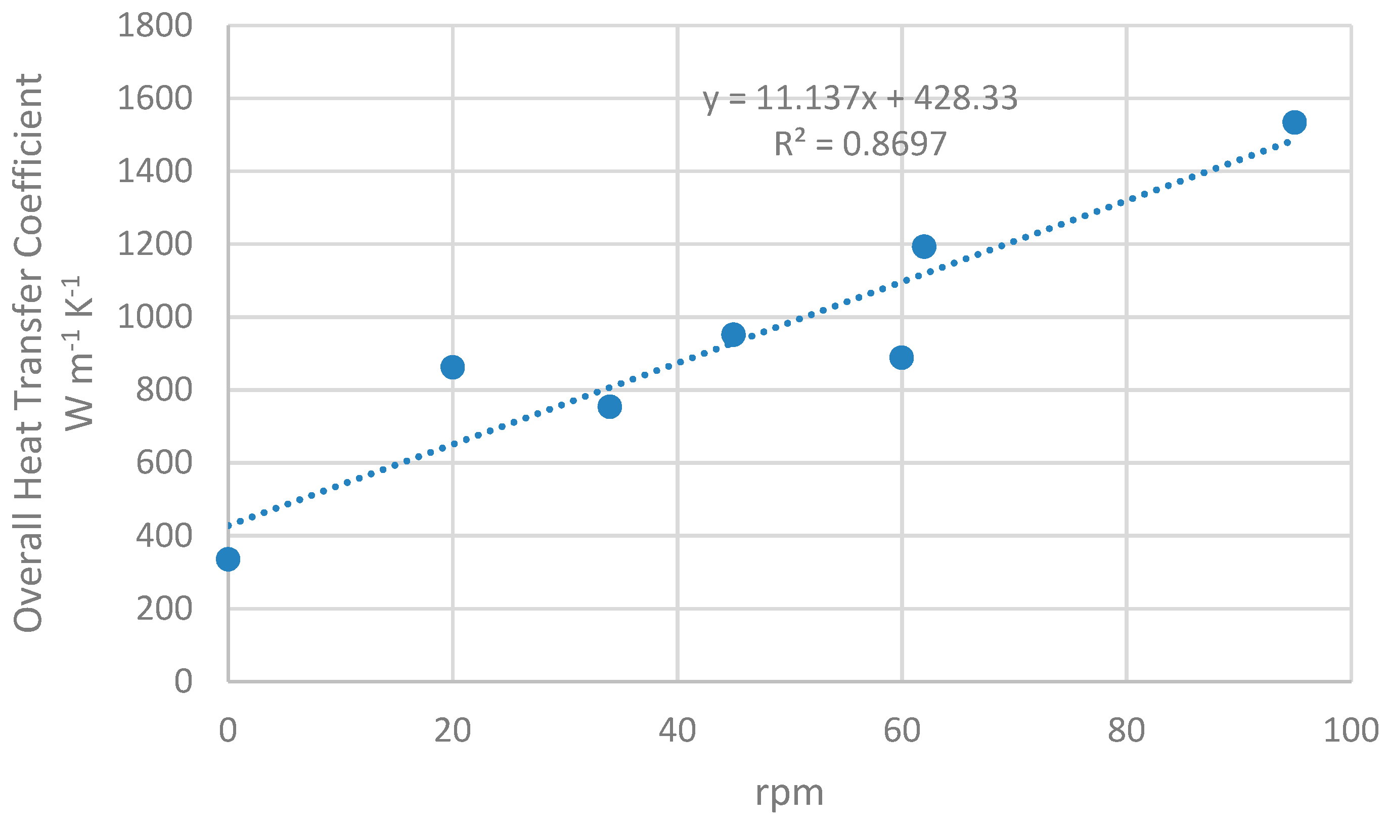
Figure 5 shows the experimental data. The relationship between both variables of interest looks linear, at least up to 100 rpm. The fact that raising the level of agitation from none to 38 rpm doubles the heat-exchange coefficient is remarkable.
3.2. Drying Blood into Blood Meal
The process of converting a fluid into a dried powder (blood meal in the case of blood) goes through four clearly identified stages: thin liquid, thick liquid, sludge, and finally powder, following that order, as heat goes through. One qualitative analysis of great importance is to determine if the drying process has come to the powder stage in a reasonable time. The experiments we conducted showed that raw blood was turned into a powder in no more than one hour. However, the final moisture content was diverse, depending upon operational conditions, but for our case experiment, it was 17% of humidity on a wet basis (one hour of drying).
On the other hand, the ratio of blood meal versus raw blood also varied with the operational conditions. The maximum amount of blood meal is limited to 19% of raw blood weight in the case of cows, as is our case. Under our experiment, we got 15% of raw blood weight transformed into blood meal.
3.3. Economic Feasibility
Table 1 shows the temperature ranges over which the waste effluent can be used with the energy-exploitation techniques described here. As can be seen, electrical power production systems are at a disadvantage, as they are impractical with effluents at temperatures below 70 °C—Their efficiency at those levels is too low and not shown in the table. Preheating and conditioning systems are substantially better, with heat pumps enabling operation at the lowest possible temperatures [6]. The device proposed in this paper comprises the use of a heat pump supplied with a condenser evaporating below 10 °C and can thus operate with effluents at temperatures above 20 °C. The fifth column displays economic performance per ton of waste effluent.
4. Discussion
4.1. Heat Exchanger Performance
The heat proposed exchanger seeks for solving a main problem in the agri-food industry: to transfer heat to sludge in an efficient and fast way, so that it can be dried in a small amount of time. Usually, sludge drying is very slow, despite the fact that it typically contains no more than 30% of the water that came with the raw liquid from which it is produced [15]. However, in usual conditions in industry, that 30% of water would take more than 60% of total drying time, which evidences that the drying of a liquid is much faster [16].
The heat exchanger presented in this paper has a geometry that allows high heat-transfer rates, even with sludge, due to its particular geometry. As previously stated, it consists of narrow vertical chambers with stirrers inside. Narrow means a width that allows heat to get to the bulk of the drying material in a short time by the mechanism of thermal conduction. This is a very important feature, since sludge tends to agglomerate and is difficult to unbundle and to be properly mixed, which means that heat transfer by convection is severely reduced, and thus conduction takes the main role [17]. This phenomenon occurs even with the stirrers, though to a lesser extent. In any case, narrow chambers guarantee good performance even in the worst scenario. For the exchanger here disclosed, a width of 50 mm means that heat should travel a maximum distance of 25 mm to reach the bulk by conduction. This distance is reduced enough to provide a reasonable heat-transfer speed [18].
The aforementioned geometry makes the exchanger fall into the plate-heat-exchanger category [19], though it has several differences. The main one is that the chambers from the typical plate heat exchangers from the current state of the art have a much shorter width, ranging from 1 to 10 mm. Another difference is that the two plates that conform every chamber make contact not only over their borders, but also on the inside [19]; this has several implications, the most important being that it would block any stirrer or agitator of any kind, making its presence impossible [19,20]. That is not the case for the here-presented technology. Since the stirring mechanisms make a big difference dealing with sludge, mainly because of their shear forces that break the boundary layer, and also allowing mixing of the drying material, it is obvious that the typical plate-heat-exchanger design does not allow for sludge handling [21]. On the other hand, the mixing of the drying material fosters heat transmission by convection [15,17], a fast heat transfer mechanism, rather than conduction, which usually is slow.
The stirrers are the feature which contributes the most to improving drying time, mostly because of boundary-layer braking [15,17]. This layer is present at every stage of the drying material (fluid, sludge, and powder) and adheres to the heat-exchange surfaces [15]. At least from a theoretical approach, if the boundary-layer thickness tends to zero, the heat-exchange rate through it tends to infinity [16]. That is what agitators do, narrow the boundary layer.
In order to test our exchanger with the best possible accuracy, we conducted an experiment comprising boiling clean water instead of a third fluid to be valorized, like blood, and also clean water as the heating fluid. In other words, two different sources of water where employed: one taking the role of the hot waste effluent, and the other the role of the third fluid to be dried. This test allows us to know the maximum achievable performance of the exchanger; it is obvious that any other fluid thicker than clean water will show poorer efficiency [15,22]. Once its maximum for water is known, it is easy to extrapolate figures for thicker fluids or sludge [15]. This experiment serves as a tool for validating the technology.
In the state of the art, there are several other devices which employ stirrers to improve the heat-transfer rate [15,18]. They are known for having very high rates, partly due to very high rotational speeds, with stirrers connected to a shaft that goes faster than 1000 rpm [10]. However, these exchangers get to the sludge stage in the best scenario, not reaching the final powder stage [15,18]. This is because powder has a tremendous stopping power that can easily block even highly powered stirrers if they are running at high speed [15]. The experiments concluded that the heat exchanger we propose should not go over 20 rpm when power has formed; otherwise, the mechanical shaft, seal, or engine could undergo major damage.
On the other hand, the experiment was limited to a maximum of 100 rpm. This is because we noticed that higher speeds generate centrifugal force strong enough to make blood escape the boiling chamber upward, reaching the vapor–liquid separator and the condenser, which would be a serious problem because that means losing blood (and hence losing blood meal) and fouling those components of the equipment that are meant to be clean, like the condenser [20]. Therefore, to sustain centrifugal force weak enough for a 500 mm diameter stirrer, rotation should not exceed 100 rpm.
From Figure 5, it is concluded that, from zero to 100 rpm, the heat exchanger shows linear dependence of the overall heat transfer coefficient with the stirrer rotational speed. For a speed higher than 100 rpm, the relation is expected not to be linear [15,16], but that is out of our scope for the aforementioned reasons.
Regarding the figures, overall heat-transfer coefficients higher than 1000 W m−2 K−1 are achieved, and close to 1600 W m−2 K−1 for 95 rpm. With higher rotational speed, coefficients would be greater [15,16]. Also, if the experiment is carried out with a higher flow rate, the overall coefficients will be higher [21,22], but it is limited here to 1500 L h−1 for practical reasons, as it is very common among slaughterhouses’ waste effluents, though it could be greater. At this point, it is important to check how they compare with up-to-date alternatives in industry. Comparable technologies are those that meet the following requirements: indirect-contact heat exchanger, 6 mm thick metallic wall, and heating medium being pumped with a flow rate of 1500 L h−1. Indirect contact implies that both the heating medium and the drying medium do not make contact but are separated by a metallic wall through which heat flow takes place [16,19]. This is compulsory when vacuum-drying at low temperatures, which is the present case. Typical direct-contact dryers in the industry work with high-temperature airflows [16], which allow fast drying, but, on the other side, would damage protein quality in the case of blood: protein denaturalization will always take place with temperatures over 70 °C [16]. The 6 mm thickness of the chamber walls could suppose a drawback with respect to the usual plate heat exchangers with walls ranging from 0.5 to 2 mm in width [19], but it is necessary to compensate for the lack of internal contact points between adjacent plates. Internal contact points would not allow stirrers, as remarked before. Their absence implies that plates with diameters larger than 0.5 m are subject to higher stress, which could potentially bend the plate and cause permanent damage [13].
The results shown in Figure 5 announce a level of performance close to the maximum achievable, given the 6 mm thick plate, that becomes the main thermal resistance. As stated before, the heat going from the heating fluid to the drying material has to go through three thermal resistances in series: boundary layer of the heating fluid, the metal plate itself, and the boundary layer of the drying material. The thicker the boundary layer, the higher its thermal resistance [12,13]. The first layer can be narrowed with higher flow rates (1500 L h−1 in our experiment), and the third with higher rotational speed. Nevertheless, the second one cannot be improved at all; hence, the overall heat-transfer coefficient will always be lower that the local one through the metal plate thickness (6 mm in this experiment) [22]. The calculations give a local heat-transfer coefficient of 2333 W m2 K−1, so this figure cannot be improved. If the three resistances were that exact same value, the overall heat-transfer coefficient would be reduced to a third of it, 777.6 W m2 K−1. This indicates very high performances for the first and third resistances. If we suppose both are equal, it would be around 10,000 W m2 K−1 for 95 rpm, which is very high.
Therefore, the metal plate is the main thermal resistance, and so in order to pursue better overall performance, the key action is to tighten it. From the experiments, it is concluded that the 6 mm thick wall could be reduced to 4 mm, as long as the plate diameter does not exceed 0.5 m. Bending of the 6 mm thick plates was measured less than 1.6 mm at their center; with the 4 mm version, it could attain up to 3 mm, but it is okay whenever that collapse is taken into account when designing the stirrers, so that they adjust well around it. In this last case, and following the same calculations as before, we arrive up to an overall heat-transfer coefficient of 2058 W m2 K−1, with 95 rpm, also for AISI316 stainless steel (thermal conductivity of 14 W m−1 K−1). If better-behaving metals could be allowed, especially those with higher conductivities, like aluminum, performance would consequently be increased [13].
The coefficients displayed so far are higher than those of the typical alternatives in the state of the art [23,24], like shell-and-tube, falling film, and plate heat exchangers [21,22,25], especially if we study their efficiency in the same conditions as stated before. To make the comparison even more reliable, clean water, as both heating fluid and boiling fluid, must be considered. This is so, in part, because the majority of heat exchangers are tested with the universal and easily repeatable conditions clean water brings; this makes comparisons more accurate [13,21,26]. The usual overall heat-transfer coefficients will range under 1000 W m2 K−1 [22,25]. In some cases, for specially designed higher performance units [27], like shell-and-tube exchanger with wirings inside the tubes and some falling film evaporators [28], the coefficient will approach 2000 W m2 K−1, but with several drawbacks. In the case of wired tubes, they are not compatible with a product to be dried up to the final stage of power, because of the retention force that the wire exerts on the sludge and falling film evaporators cannot dry products—they can just concentrate them [13,15]. Furthermore, some specific plate heat exchangers can yield coefficients over 5000 W m2 K−1, but they are absolutely incapable of dealing with sludge, so the comparison makes no sense [16].
4.2. Drying Blood into Blood Meal
The amount of blood meal recovered is under the theoretical maximum of 19%, since we got 15% [29]. This is owing to the fact that a fraction of the sludge remained attached to the stirrers [15]. These remains could be detached by devoting some time to cleaning the stirrers at the end of the process, but for practical reasons, we only considered that quantity easily extracted, with little effort in a time under five minutes, once the process stopped. This way arrived at 15%. Furthermore, this reduced the quantity extracted in the case of just one operation. If we make two or more consecutive operations, without interposing cleaning cycles in between, the recovered meal would be near the theoretical maximum [15].
Regarding moisture content, the heat exchanger was capable of rendering blood meal with 17% of water content in a wet basis. This was the result for process conditions comprising a thermal difference over 30 K, 60 rpm, and a drying time of an hour. For commercial purposes, and to comply with technical standards, moisture should not exceed 11% in a wet basis [29,30], so the result suggests a bit more time is needed, with 75 min being the preferred time.
From the qualitative point of view, the main analysis to be considered is to verify the process carried out by the exchanger goes correctly through the four stages: thin liquid, thick liquid, sludge, and finally powder (blood meal) [15]. This sequence is completed in about 45 min, which evidences the suitability of the exchanger design, being remarkable in its structure, which is based on narrow vertical cylindrical chambers with stirrers in its inside. The stirrers make contact with the heat-exchange surface, acting as scrapers, that have three main benefits: they increase heat-exchange coefficient, which allows those figures over 1.000 W m−2 K−1 [13], help remove attached particles and prevent fouling, and subject sludge to high shear forces that are responsible for the disaggregation process that transforms it into powder [15].
The blood meal was obtained at temperatures not higher than 43 °C, being achievable at a constant boiling temperature of 35 °C, by means of the liquid ring vacuum pump. These temperatures are very low in comparison with the technical alternatives currently available [29]. Among the preferred technologies are the ring dryer and spray dryer [13]. Both of them are direct-contact dryers; they dry blood by making a hot airflow pass through it, at temperatures well over 100 °C, commonly over 170 °C. Despite the fact that the contact lasts only a split second, protein denaturalization takes place. In order to fully prevent it, it is necessary to lower temperatures under 70 °C. This way, very high digestibility proteins are recovered, and this has a direct impact on market price [31].
4.3. Economic Feasibility
In view of the results presented in Table 1, it is clear that interposing a third fluid to be valorized by drying is the most profitable technique, overcoming even the preheating of process fluids, which is probably the most profitable technique of the previous state of the art. Its main problem is that it is subject to the market value of the dehydrated product obtained. For the case of blood meal, we are considering a conservative estimation of 400 € t−1 (it has attained 1800 € t−1 in the USA in recent years), but it depends on laws of supply and demand, so it could fluctuate, and there is a need to seek for a trade channel where it can be sold. Furthermore, in many industries, the fluid to be valorized through drying could be a much less profitable one, so figures could change, and one could also take into consideration some additional marketing costs related to the dried product. Nevertheless, the technical solution presented in this paper represents an important improvement for industries with interesting by-products that can be dehydrated [31].
The third row of Table 1 represents the technology of our current prototype, whose heat exchanger was depicted in Figure 3. The fourth row of Table 1 represents an improvement that consists of implementing a system of three multiple-effect evaporators in series. Each evaporator comprises one plate heat exchanger, like that of Figure 3. This improvement can rise valorization up to a 50% more, at the expense of a most costly equipment. More specifically, this would involve an increment in cost of about 80%, but at the same time, energy consumption lowers drastically from 287 to 115 € t−1. This last option is the most profitable one, but it requires higher initial inversion.
5. Patents
ES2601932B2 “Device and procedure for obtaining a dried product from blood or derivatives”.
ES2597584B2 “System for drying liquid blood”.
Author Contributions
Conceptualization, J.M.M.-A. and H.V.-R.; investigation, J.M.M.-A. and H.V.-R.; writing—original draft preparation, J.M.M.-A., H.V.-R. and A.L.-F.; writing—review and editing, H.V.-R. and A.L.-F.; project administration, J.M.M.-A. and A.L.-F.; funding acquisition, J.M.M.-A. and A.L.-F. All authors have read and agreed to the published version of the manuscript.
Funding
This research was partiality supported by the Strategic Researcher Cluster BioReDeS, funded by the Regional Government Xunta de Galicia, under the project ED431E 2018/09.
Acknowledgments
The authors acknowledge Lugo Carne S.L. for kindly allowing the assembly and testing of the system in its facilities. They also thank the award of the best applied research work 2017 of the Royal Academy of Sciences of Galicia, whose endowment allowed the first experimental assembly of the system.
Conflicts of Interest
The authors declare no conflicts of interest. The funders had no role in the design of the study; in the collection, analyses, or interpretation of data; in the writing of the manuscript; or in the decision to publish the results.
References
- Nazari, L.; Sarathy, S.; Santoro, D.; Ho, D.; Ray, M.B.; Xu, C. Recent advances in energy recovery from wastewater sludge. In Direct Thermochemical Liquefaction for Energy Applications, 1st ed.; Rosendahl, L., Ed.; Woodhead Publishing: Duxford, UK, 2018; pp. 67–100. [Google Scholar]
- Moran, M.; Shapiro, H. Fundamentals of Engineering Thermodynamics, 8th ed.; John Wiley & Sons Inc.: Hoboken, NJ, USA, 2014; pp. 357–512. [Google Scholar]
- Schmid, F. Sewage water: Interesting heat source for heat pumps and chillers. In Proceedings of the 9th International IEA Heat Pump Conference, Zürich, Switzerland, 20–22 May 2008. [Google Scholar]
- Blanco-Orús, R.; García-Ramos, F.J. Calefacción de instalaciones de porcino con suelo radiante de agua caliente. Mundo Ganad. 2013, 252, 48–52. [Google Scholar]
- Jouhara, H.; Khordehgah, N.; Almahmoud, S.; Delpech, B.; Chauhan, A.; Tassou, S.A. Waste heat recovery technologies and applications. Therm. Sci. Eng. Prog. 2018, 6, 268–289. [Google Scholar] [CrossRef]
- Cipolla, S.S.; Maglionico, M. Heat recovery from urban wastewater: Analysis of the variability of flow rate and temperature in the sewer of Bologna, Italy. Energy Procedia 2014, 45, 288–297. [Google Scholar] [CrossRef] [Green Version]
- Haddad, C.; Périlhon, C.; Danlos, A.; François, M.X.; Descombes, G. Some efficient solutions to recover low and medium waste heat: Competitiveness of the thermoacoustic technology. Energy Procedia 2014, 50, 1056–1069. [Google Scholar] [CrossRef]
- Hao, X.; Li, J.; van Loosdrecht, M.C.M.; Jiang, H.; Liu, R. Energy recovery from wastewater: Heat over organics. Water Res. 2019, 161, 74–77. [Google Scholar] [CrossRef] [PubMed]
- Stillwell, A.S.; Hoppock, D.C.; Webber, M.E. Energy Recovery from Wastewater Treatment Plants in the United States: A Case Study of the Energy-Water Nexus. Sustainability 2010, 2, 945–962. [Google Scholar] [CrossRef] [Green Version]
- McCabe, W.; Smith, J.; Harriot, P. Unit Operations of Chemical Engineering, 7th ed.; McGraw-Hill Education: New York, NY, USA, 2004; pp. 273–750. [Google Scholar]
- Yunta, F.; Di Foggia, M.; Bellido-Díaz, V.; Morales-Calderón, M.; Tessarin, P.; López-Rayo, S.; Tinti, A.; Kovács, K.; Klencsár, Z.; Fodor, F.; et al. Blood Meal-Based Compound. Good Choice as Iron Fertilizer for Organic Farming. J. Agric. Food Chem. 2013, 61, 3995–4003. [Google Scholar] [CrossRef]
- Perry, R.H.; Green, D.W. Perry’s Chemical Engineer’s Handbook, 9th ed.; McGraw-Hill Education: New York, NY, USA, 2009; pp. 150–1570. [Google Scholar]
- Coulson, J.M.; Richardson, J.F.; Sinnott, R.K. Coulson and Richardson’s Chemical Engineering: Chemical Engineering Design, 4th ed.; Butterworth-Heinemann: Oxford, UK, 2010; pp. 358–512. [Google Scholar]
- Khanam, S.; Mohanty, B. Energy Reduction Schemes for Multiple Effect Evaporator Systems. Appl. Energy 2010, 87, 1102–1111. [Google Scholar] [CrossRef]
- Mujumdar, A.S. Handbook of Industrial Drying, 3rd ed.; CRC Press: Boca Raton, FL, USA, 2006; pp. 915–1200. [Google Scholar]
- Kudra, T.; Mujumdar, A.S. Advanced Drying Technologies, 2nd ed.; CRC Press: Boca Raton, FL, USA, 2009; pp. 57–250. [Google Scholar]
- Afonso, I.M.; Cruz, P.; Maia, J.M.; Melo, L.F. Simplified numerical simulation to obtain heat transfer correlations for stirred yoghurt in a plater heat exchanger. Food Bioprod. Process. 2008, 87, 296–303. [Google Scholar] [CrossRef]
- Afonso, I.M.; Hes, L.; Maia, J.M.; Melo, L.F. Heat transfer and rheology of stirred yoghurt during cooling in plate heat exchangers. J. Food Eng. 2003, 57, 179–187. [Google Scholar] [CrossRef] [Green Version]
- Fernandes, C.S.; Dias, R.; Nóbrega, J.M.; Afonso, I.M.; Melo, L.F.; Maia, J.M. Simulation of stirred yoghurt processing in plate heat exchangers. J. Food Eng. 2005, 69, 281–290. [Google Scholar] [CrossRef] [Green Version]
- Kanaris, A.G.; Mouza, A.A.; Paras, S.V. Optimal design of a plate heat exchanger with undulated surfaces. Int. J. Therm. Sci. 2009, 48, 1184–1195. [Google Scholar] [CrossRef]
- Pinson, F.; Gregoire, O.; Quintard, M.; Prat, M.; Simonin, O. Modeling of turbulent heat transfer and thermal dispersion for flows in flat plate heat exchangers. Int. J. Heat Mass Transf. 2007, 50, 1500–1515. [Google Scholar] [CrossRef]
- Gut, J.A.W.; Fernandes, R.; Pinto, J.M.; Tadini, C.C. Thermal model validation of plate heat exchangers with generalized configurations. Chem. Eng. Sci. 2004, 59, 4591–4600. [Google Scholar] [CrossRef]
- Abd, A.A.; Kareem, M.Q.; Naji, S.Z. Performance analysis of shell and tube heat exchanger: Parametric study. Case Stud. Therm. Eng. 2018, 12, 563–568. [Google Scholar] [CrossRef]
- Deng, W.; Su, Y.; Yu, W. Theoretical calculation of heat transfer coefficient when sludge drying in a nara-type paddle dryer using different heat carriers. Procedia Environ. Sci. 2013, 18, 709–715. [Google Scholar] [CrossRef] [Green Version]
- Pathak, S.; Sahu, H.S. CFD Analysis of Heat Transfer Enhancement in Shell and Tube Type Heat Exchanger creating Triangular Fin on the Tubes. Int. J. Trend Sci. Res. Dev. 2018, 2, 1161–1170. [Google Scholar] [CrossRef] [Green Version]
- Gowthamam, P.S.; Satish, S. Analysis of Segmental and Helical Baffle in Shell and tube Heat Exchanger. Int. J. Curr. Eng. Technol. 2014, 2, 625–628. [Google Scholar] [CrossRef]
- Gupta, V.; Dewangan, R. Analytical Comparison of Different Geometrical Shapes of Tubes of Shell & Tube Heat Exchanger. Int. J. Sci. Res. Dev. 2017, 5, 508–511. [Google Scholar]
- Shendre, M.; Biradar, S. Experimental Study on Heat Transfer and Fluid Flow Characteristics of Shell and Tube Heat Exchanger using hiTRAN Wire Inserts. Int. J. Trend Sci. Res. Dev. 2018, 2, 572–579. [Google Scholar]
- Ockerman, H.W.; Hansen, C.L. Animal By-Product Processing & Utilization, 1st ed.; CRC Press: Boca Raton, FL, USA, 1999; pp. 210–253. [Google Scholar]
- Warris, P.D. Meat Science: An Introductory Text, 2nd ed.; CABI: Wallingford, UK, 2009; pp. 45–157. [Google Scholar]
- Babale, D.M.; Charity, A.M.; Shehu, J.F. Economic Evaluation of replacing Fishmeal meal with Blood Meal in broiler production in Mubi, Adamawa State, Nigeria. Int. J. Manag. Soc. Sci. Res. 2012, 1, 36–40. [Google Scholar]
Figure 1.
Heat exchange by use of 3 thermal resistances. (1) Metal plate. (3) Hot-fluid boundary layer. (6) Cold-fluid boundary layer. The boundary layers are depicted as dashed lines of exaggerated thickness for clarity.
Figure 1.
Heat exchange by use of 3 thermal resistances. (1) Metal plate. (3) Hot-fluid boundary layer. (6) Cold-fluid boundary layer. The boundary layers are depicted as dashed lines of exaggerated thickness for clarity.

Figure 2.
Heat exchange with six thermal resistances. (1) Metal plates in the exchangers. (2) Bridge. (3) Waste effluent boundary layer. (4) Third-fluid boundary layer in first exchanger. (5) Condensed vapor layer in second exchanger. (6) Cold-fluid boundary layer. (7) Evacuated boiling chamber. The boundary layers are depicted as dashed lines of exaggerated thickness for clarity.

Figure 3.
Partial cross-sectional view of a heat exchanger, including stirrers. (1) Metal plates for thermal exchange. (8) External motor. (9) Rotary axle actuating the stirrers. (10) Chassis. (11) Stirrers.
Figure 3.
Partial cross-sectional view of a heat exchanger, including stirrers. (1) Metal plates for thermal exchange. (8) External motor. (9) Rotary axle actuating the stirrers. (10) Chassis. (11) Stirrers.
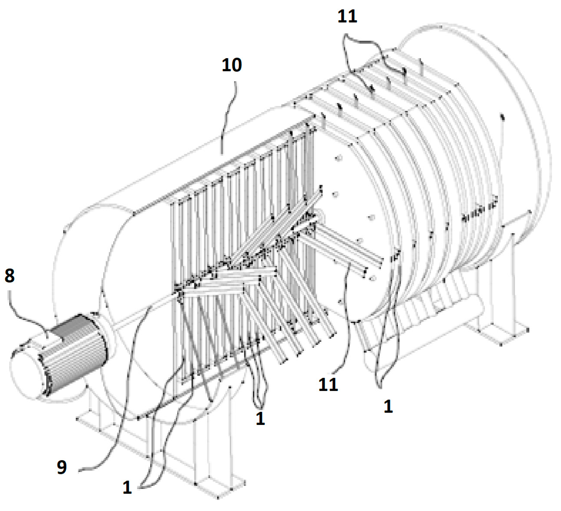
Figure 4.
Flowchart of a system for extracting energy from waste effluents including a heat pump and three evaporators.
Figure 4.
Flowchart of a system for extracting energy from waste effluents including a heat pump and three evaporators.
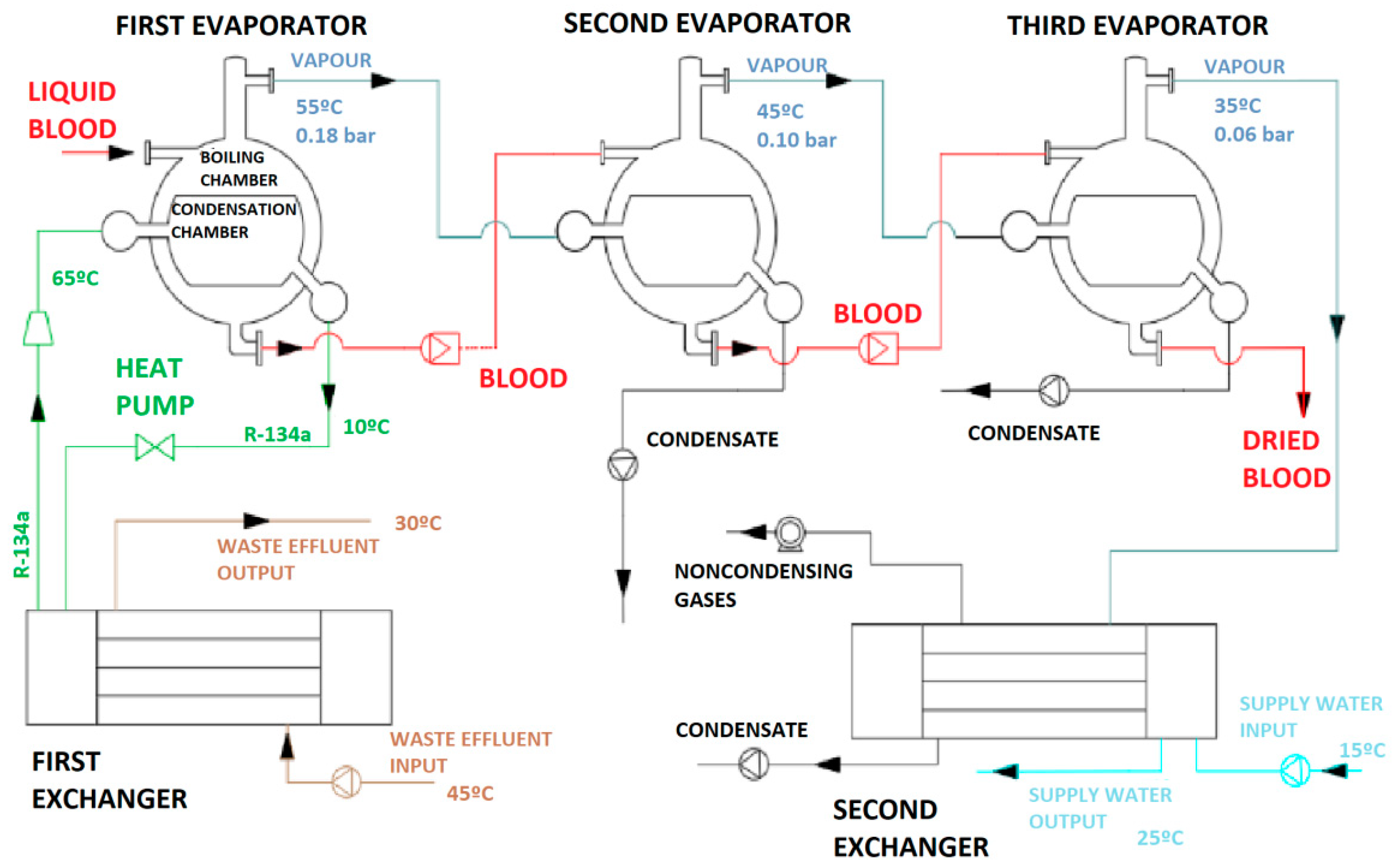
Figure 5.
Heat exchanger performance: heat-exchange coefficient in relation to rotation speed of the stirrer.
Figure 5.
Heat exchanger performance: heat-exchange coefficient in relation to rotation speed of the stirrer.

Table 1.
Comparison of economic feasibility among major techniques for exploiting energy from waste effluents and producing blood meal (refereed to a ton of waste effluent).
Table 1.
Comparison of economic feasibility among major techniques for exploiting energy from waste effluents and producing blood meal (refereed to a ton of waste effluent).
| Technique | Temperature (°C) | Recovered Energy (MJ t−1) | Blood Meal (kg t−1) | Valorization (€ t−1) |
|---|---|---|---|---|
| Conditioning of Dwellings | 40–80 | 167.47 | - | 3.20 |
| Preheating of Process Fluids | 40–80 | 167.47 | - | 3.20 |
| Drying with a Heat Pump | 20–80 | 251.21 | 16.69 | 6.70 |
| Drying with a Heat Pump and Three Evaporators | 20–80 | 251.21 | 16.69 | 9.57 |
© 2020 by the authors. Licensee MDPI, Basel, Switzerland. This article is an open access article distributed under the terms and conditions of the Creative Commons Attribution (CC BY) license (http://creativecommons.org/licenses/by/4.0/).
Share and Cite
MDPI and ACS Style
Magide-Ameijide, J.M.; Varela-Rodríguez, H.; López-Fabal, A. A New Technique for Improved Use of Thermal Energy from Waste Effluents. Agronomy 2020, 10, 97. https://doi.org/10.3390/agronomy10010097
AMA Style
Magide-Ameijide JM, Varela-Rodríguez H, López-Fabal A. A New Technique for Improved Use of Thermal Energy from Waste Effluents. Agronomy. 2020; 10(1):97. https://doi.org/10.3390/agronomy10010097
Chicago/Turabian StyleMagide-Ameijide, José Manuel, Hiram Varela-Rodríguez, and Adolfo López-Fabal. 2020. "A New Technique for Improved Use of Thermal Energy from Waste Effluents" Agronomy 10, no. 1: 97. https://doi.org/10.3390/agronomy10010097
Note that from the first issue of 2016, this journal uses article numbers instead of page numbers. See further details here.