Article

Assisted Tea Leaf Picking: The Design and Simulation of a 6-DOF Stewart Parallel Lifting Platform

College of Tea Science, Yunnan Agricultural University, Kunming 650201, China
*
Author to whom correspondence should be addressed.
Agronomy 2024, 14(4), 844; https://doi.org/10.3390/agronomy14040844
Submission received: 7 March 2024 / Revised: 14 April 2024 / Accepted: 16 April 2024 / Published: 18 April 2024
(This article belongs to the Special Issue AI, Sensors and Robotics for Smart Agriculture—2nd Edition)

Abstract

:
The 6-DOF Stewart parallel elevation platform serves as the platform for mounting the tea-picking robotic arm, significantly impacting the operational scope, velocity, and harvesting precision of the robotic arm. Utilizing the Stewart setup, a parallel elevation platform with automated lifting and leveling capabilities was devised, ensuring precise halts at designated elevations for seamless harvesting operations. The effectiveness of the platform parameter configuration and the reasonableness of the posture changes were verified. Firstly, the planting mode and growth characteristics of Yunnan large-leaf tea trees were analyzed to determine the preset path, posture changes, and mechanism stroke of the Stewart parallel lifting platform, thereby determining the basic design specifications of the platform. Secondly, a 3D model was established using SolidWorks, a robust adaptive PD control model was built using MATLAB for simulation, and dynamic calculations were carried out through data interaction in Simulink and ADAMS. Finally, the rationality of the lifting platform design requirements was determined based on simulation data, a 6-DOF Stewart parallel lifting platform was manufactured, and a motion control system was built for experimental verification according to the design specifications and simulation data. The results showed that the maximum deviation angle around the X, Y, and Z axes was 10°, the maximum lifting distance was 15 cm, the maximum load capacity was 60 kg, the platform response error was within ±0.1 mm, and the stable motion characteristics reached below the millimeter level, which can meet the requirements of automated operation of the auxiliary picking robotic arm.

1. Introduction

China is the country with the largest planting area and highest output of large-leaf Pu’er tea trees in the world. The planting of large-leaf Pu’er tea trees is mainly concentrated in four major production areas in the southwest of Yunnan Province, namely Pu’er City, Xishuangbanna, Lincang, and Baoshan. The total planted area of tea gardens is 11,700 hectares, with a total output of about 195,000 tons [1,2]. However, the cultivation of large-leaf Pu’er tea trees relies heavily on manual labor for tea picking, which is a labor-intensive and important agricultural occupation. Consequently, the low degree of mechanization, low picking efficiency, and difficulty in ensuring the picking quality have become increasingly prominent problems [3,4,5].
Currently, research on tea-picking robots mainly focuses on the optimization and design of the structure of tea leaf image recognition and positioning [6,7,8,9,10,11], picking manipulators [12,13,14,15], and end effectors [16,17]. Hualin Yang et al. used a particle swarm optimization-support vector machine algorithm and deep convolutional neural network model to recognize and locate fresh tea leaves. They employed a Delta parallel manipulator equipped with a cutting blade for tea-picking operations, but the success rate of picking was low and there was significant damage to the tender tea buds [18]. Kondo et al. used a Mitsubishi RH-6SH5520 four-degree-of-freedom manipulator arm to develop a tomato-picking robot. After locating the picking point, the robot utilized a microcontroller to control the blade for cutting. The picking time was 15 s, with a success rate of 50%. In practical agricultural environments, picking tea leaves is affected by factors such as the angle of the leaves, leaf density, and leaf obstruction [19,20,21,22,23]. Therefore, higher requirements are placed on the performance of the manipulator arm [24,25]. Additionally, due to the small and tender nature of tea leaves, different lengths and positions of the manipulator arm are required for picking at different spatial coordinates. However, the manipulator arm has a large volume, complex structure, high inertia, and high cost [26,27,28].
A 6-DOF Stewart parallel lifting platform is a highly flexible and precise mechanical device with unique application advantages in the field of agriculture [23]. This platform can achieve precise adjustment of height, direction, and posture through the control of multiple degrees of freedom, making it very suitable for assisted agricultural harvesting [29]. Firstly, the multi-axis motion system of the 6-DOF Stewart parallel lifting platform can quickly and accurately locate the target position, making the operation of the harvesting robotic arm more efficient [30]. Secondly, this platform has a large working range and stability, able to carry a certain weight of harvesting tools and collection containers, improving harvesting efficiency and quality [31]. Additionally, the 6-DOF Stewart parallel lifting platform has a high level of intelligence, enabling automated production management and operation planning through advanced control algorithms and human–machine interfaces [32]. Therefore, the 6-DOF Stewart parallel lifting platform has obvious advantages and application prospects in the field of agricultural assisted harvesting, providing agricultural practitioners and agricultural extension professionals with more efficient and convenient assisted harvesting solutions, and promoting the modernization and intelligence of agricultural production.
In summary, the Stewart parallel lifting platform can be used as a supplement to reduce the design difficulty and cost of the picking manipulator arm and end effectors, and to reduce the computational load of the neural network visual recognition model [33,34,35,36,37]. However, there is currently no stable and reliable lifting platform specifically designed for tea leaf picking in the tea machinery field. Such a platform should meet technical requirements such as lifting height, certain load capacity, and angle adjustment [38,39]. Therefore, developing a 6-DOF Stewart parallel lifting platform with automatic lifting, leveling and orientation adjustment, and high stability is of great value for achieving efficient and automated tea leaf picking.
Based on the Stewart configuration, this study designed a parallel lifting platform specifically for a harvesting manipulator. With this platform, the harvesting manipulator can complete tea picking at a certain height and can then continue operations at another height while maintaining stability during the lifting process [40]. The application of this technology not only enhances agricultural productivity but also reduces labor costs and minimizes mechanical equipment wear and tear, thereby promoting the advancement of smart agriculture. It provides an important solution for agricultural practitioners and extension professionals to adopt precision agriculture practices to improve sustainable auxiliary tea-harvesting mechanization [41,42].

2. Materials and Methods

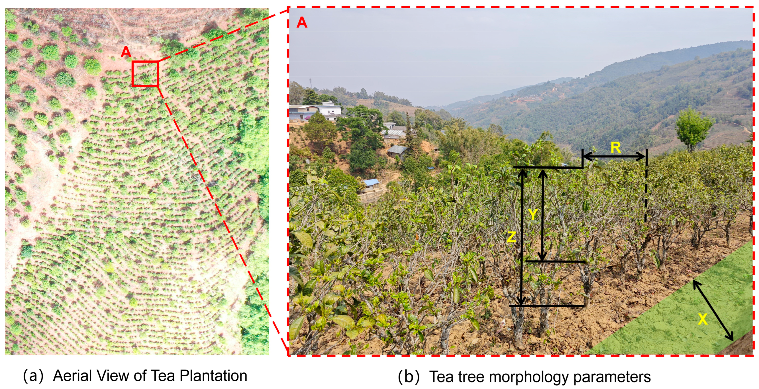
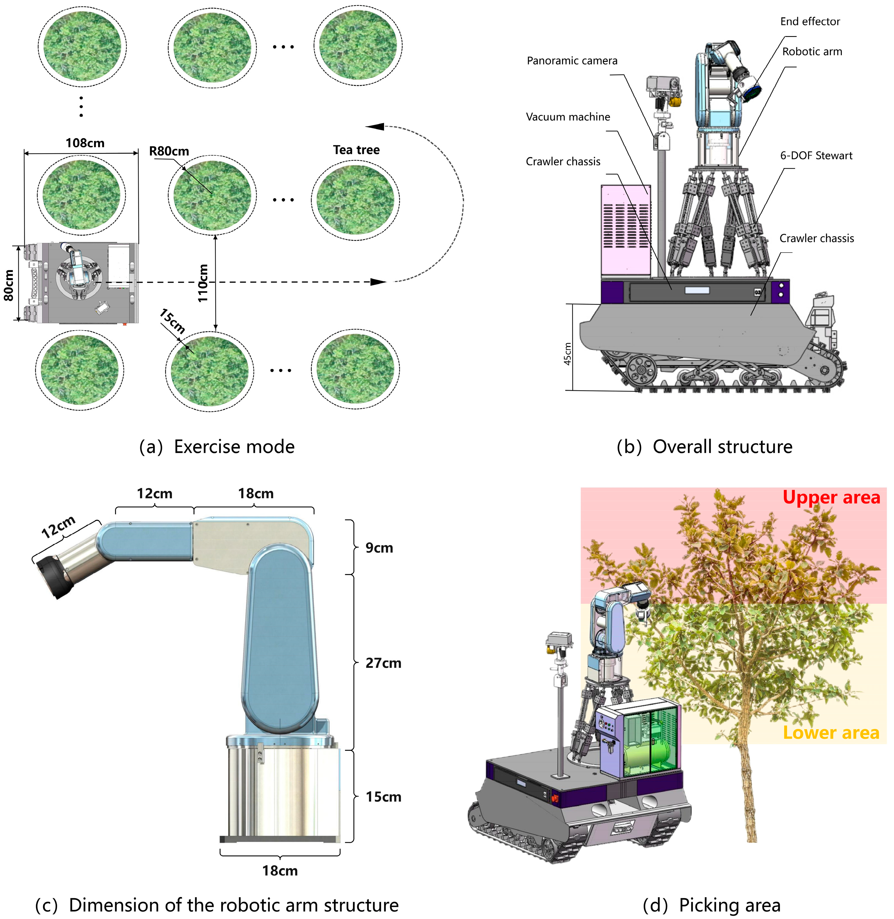
2.1. Analysis of Tea Planting Environment and Picking Process

The 6-DOF Stewart parallel lifting platform designed in this study is mainly aimed at assisting the harvesting of fresh leaves from Yunnan large-leaf tea trees, which are of the small arbor type, under the current single-cultivar intensive management system with spaced planting patterns [1,2] (Figure 1a). In this planting mode, the design of the 6-DOF Stewart parallel lifting platform first needs to adapt to the cultivation dimensions of tea trees under this planting mode, with the tea tree cultivation parameters shown in Figure 1b. The specific parameters are shown in Table 1, where R is the radial growth radius of the canopy, Z is the height of the tea tree, Y is the height of the tea tree crown, and X is the operating lane. The tea leaves are randomly scattered on the surface of the tea tree crown. When the robot harvests tea leaves at different heights, it requires mechanical arms of different lengths and positions. Therefore, the picking process can start from the bottom of the crown and can then be assisted by the Stewart parallel lifting platform to raise the height and facilitate the tea-picking operation of the manipulator arm.
The 6-DOF Stewart parallel lifting platform in this study needs to meet the design dimensions of the robot’s chassis and harvesting manipulator to adapt to auxiliary harvesting operations. Based on the physical parameters of Yunnan large-leaf type tea trees grown in a row/column spacing planting pattern, to ensure that the tea harvesting robot equipment does not collide with the trees, leaving a space of 15 cm on both sides of the operating lane is required to meet the walking requirements of the chassis. The length and width dimensions of the tea-harvesting robot chassis structure and its “S” motion mode are illustrated in Figure 2a. Figure 2b shows the schematic diagram of the installation structure between the 6-DOF Stewart parallel lifting platform and the mobile chassis, as well as the height of the mobile chassis. The specific structure and dimensions of the picking manipulator arm are shown in Figure 2c. As shown in Figure 2d, the picking area of the Yunnan large-leaf small arbor-type tea tree canopy in the planting mode with row-column spacing, where the yellow area is the lower part of the canopy, and the red area is the upper part of the canopy. The picking manipulator arm is set on a 6-DOF Stewart parallel lifting platform, which lifts the arm to achieve the auxiliary picking operation from the lower part of the canopy to the upper part during the picking process.
Based on the specified parameters and design requirements of the tea-picking robot, including the chassis height, picking range of the robotic arm, and effective height of large-leaved, small arbor-type tea trees, the fundamental parameters of the Stewart parallel lifting platform have been established. It is designed to have an initial height of 60 cm to meet the working requirements of a 15° pitch angle change, an 18 cm lift, and a 60 kg load. The design includes 6 driving linkages located below the moving platform, with the other ends of the linkages set on the fixed platform. The fixed platform’s ear seat hinge points form a Y-axis symmetric hexagon, and both the moving platform and the fixed platform adopt a layout with a 120° distribution angle between the linkages. When installing each linkage, the short side H1 of the moving platform corresponds to the long side H2 of the fixed platform. The spatial relationship and the structural diagram of the hinge points for the 6-DOF Stewart parallel lifting platform for tea leaf picking are shown in Figure 3 below.

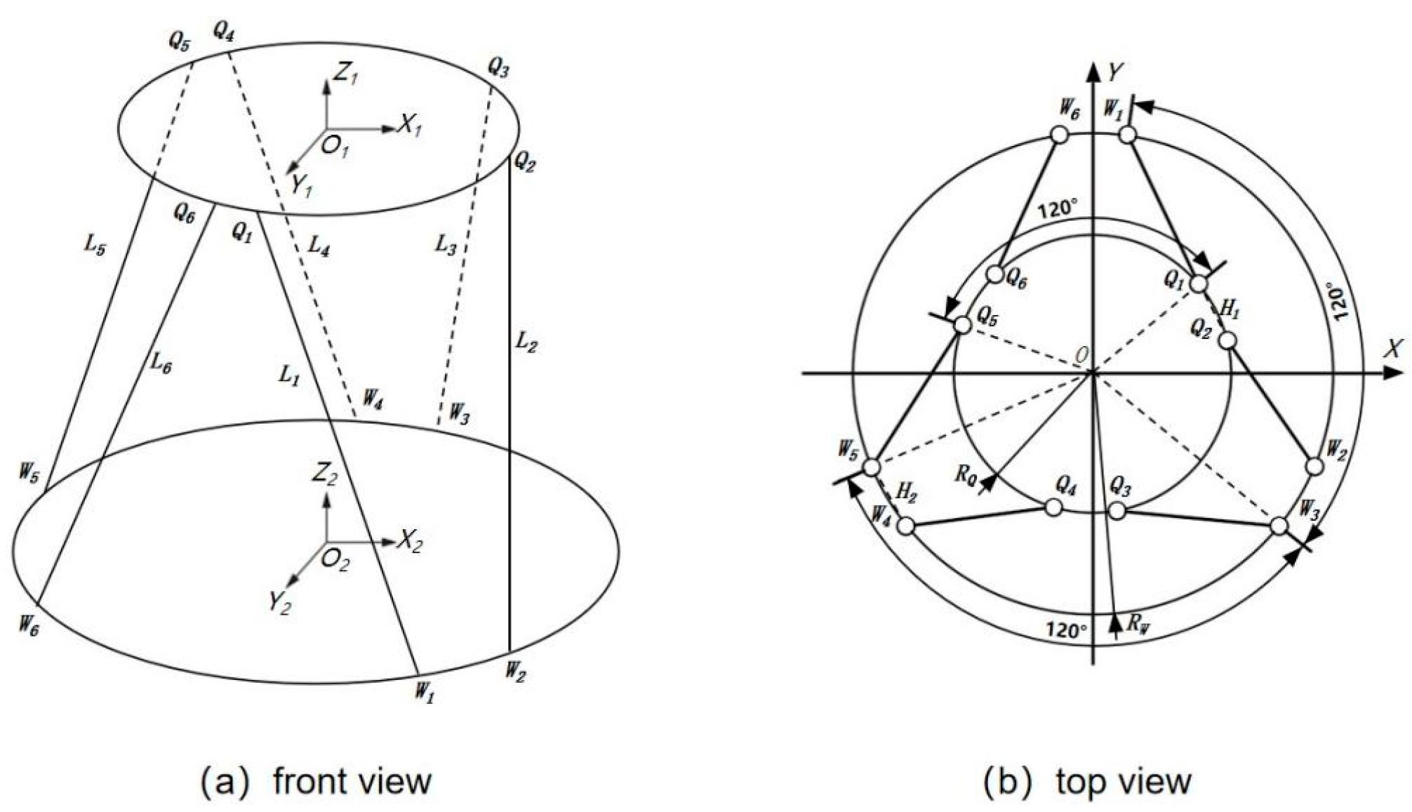
2.2. Modeling and Analysis of Stewart Parallel Lifting Platform

SolidWorks 2023 (Dassault Systèmes Co., Paris, France) is a professional 3D modeling software application widely used in engineering design and manufacturing fields. It features powerful modeling and simulation capabilities, enabling users to create complex 3D models and assemblies quickly and efficiently [43]. Based on SolidWorks, a three-dimensional model of the tea-harvesting robot was constructed, and the Stewart parallel lifting platform shown in Figure 4 was designed. This was carried out to verify whether the design dimensions are reasonable, whether there is any motion interference with other devices when the motion platform reaches its limit position, and whether there is any motion interference between the motion platform of the parallel lifting platform itself and the internal mechanism of the device when it reaches its limit position. This allows for a rational assessment of the mechanical structure design of the Stewart parallel lifting platform [44]. Additionally, the establishment of a three-dimensional model laid the foundation for subsequent simulations. These simulations serve as a basis for innovative optimization, strength verification, fatigue life assessment, and other aspects of the research in the subsequent stages. To ensure accurate subsequent simulations, during the component assembly process, the drive motor cylinder sleeve, orientation mechanism, and lifting mechanism were, respectively, secured with bolts and adjusted with appropriate clearances to replicate a real-life scenario. Furthermore, differential pressure displacement sensors, inertial sensors, and photoelectric limit switches were installed internally and externally on the drive motor cylinder sleeve.

2.3. Extreme Position Motion Interference Analysis

In order to avoid motion interference in the mechanical structure of the Stewart parallel lifting platform during lifting, rotating, and moving processes due to unreasonable design, it is necessary to analyze the possible motion interference of the six-degree-of-freedom parallel platform in various extreme postures, including the rotation and tilt interference of the ear cups, the driving range of each joint of the six support chains, whether the driving motor interferes with the moving platform when driving the lifting mechanism to extend and retract, and whether it interferes with the support of the stationary platform.
The 16 extreme positions and postures of the Stewart parallel lifting platform that meet the job requirements are shown in Figure 5, including the maximum and minimum rotation angles of roll, pitch, and yaw in the X, Y, and Z directions; the maximum and minimum displacement values in the lateral, longitudinal, and vertical directions in the X, Y, Z three-dimensional space; and 4 combination extreme positions and postures. The detailed analysis and explanation of the specific solution formula will be presented in Section 2.4. This study uses the kinematic tools in SolidWorks to set the kinematic parameters and motion paths of the three-dimensional mode, then simulates the motion of the Stewart platform using motion analysis tools, and finally performs interference detection analysis using the CVS (Collision Visualization System). The verification results show that there is no motion interference in the extreme postures and that the design parameters of the Stewart parallel lifting platform model meet the requirements.

2.4. Kinematic Solutions

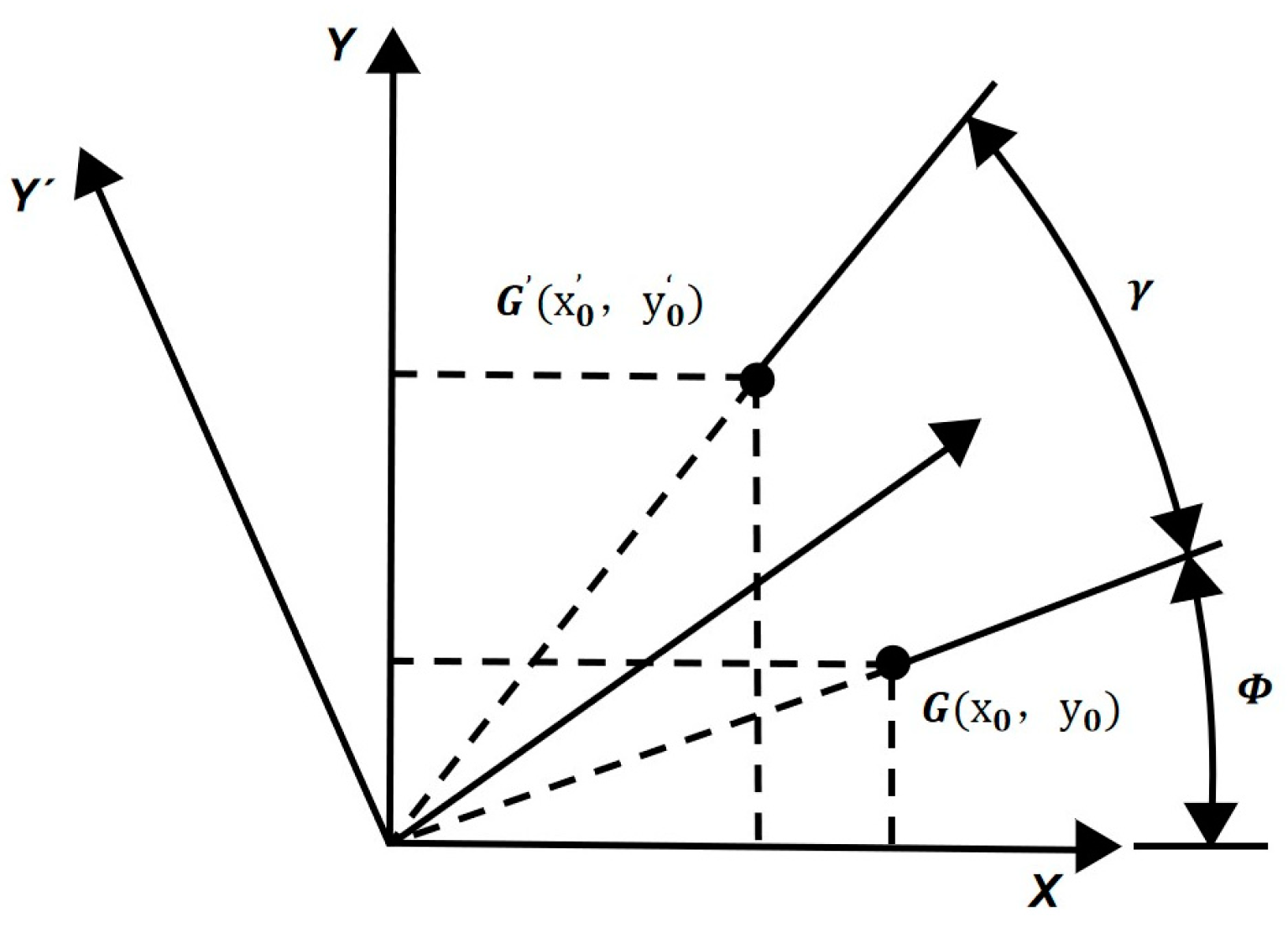
2.4.1. Analysis of Spatial Attitude Coordinate Transformation

In the initial configuration, the mobile platform preserves a parallel alignment with the stationary platform, and the primary centroid of the mobile platform remains constant while undergoing inclination at a specified angle in any direction. This situation gives rise to a spatial attitude coordinate transformation, wherein the alterations in the lengths of the six supporting chain lifting mechanisms correspond to changes in the tilt angle. Consequently, the coordinates within the identical coordinate system, both in their initial state and following inclined rotation, are depicted in Figure 6.
Rotation about the Z -axis: The initial coordinates are denoted as X O Y , and a rotation about the Z -axis by a yaw angle γ results in the coordinate system X O Y . Let G represent the point corresponding to the transformed coordinates after the coordinate transformation, denoted as G , i.e., G = R Z , γ G , which implies that
x 0 = G O ¯ cos   ( γ + ϕ ) = x 0 cos γ y 0 sin γ
In a similar manner, y 0 = G O ¯ sin   ( γ + ϕ ) = x 0 sin γ + y 0 cos γ , while z 0 = z 0 . The transformation matrix is as follows:
x 0 y 0 z 0 = cos γ sin γ 0 sin γ cos γ 0 0 0 1 x 0 y 0 z 0
which implies that
R Z , γ = cos γ sin γ 0 sin γ cos γ 0 0 0 1
Simultaneously, the transformation matrix representing the simultaneous rotation of the coordinate system around the Y-axis and X -axis by the yaw angle β and roll angle α , respectively, can be expressed as follows:
R Y , β = cos β 0 sin β 0 1 0 sin β 0 cos β
R X , α = 1 0 0 0 cos α sin α 0 sin α cos α
Therefore, it can be deduced that the rotation transformation matrix of the global coordinate system is represented by R = R X , α R Y , β R Z , γ , and the matrix form of the transformation is as follows:
R = sin β cos γ cos γ sin β sin β sin α sin β cos γ cos α sin γ sin α sin β sin γ + cos α cos γ sin α cos β cos α sin β cos γ + sin α sin γ cos α sin β sin γ sin α cos γ cos α cos β

2.4.2. Position Analysis

In the context, taking the lifting mechanism as the research object, the displacement values of the lifting mechanism are determined through the utilization of a spatial coordinate transformation and an inverse calculation, based on the known spatial pose of the platform. As depicted in Figure 3 above, it can be observed that, under the given conditions of the dynamic platform radius R q and the fixed platform radius R w , the hinge points Q i ,   W i   i = 1 ,   2 ,   ,   6   can be expressed in their respective coordinate systems, thereby determining the length vector L i that drives the lifting mechanism, as follows:
L i = R Q i + E i W i   ( i = 1 ,   2 ,   ,   6 )
The assumption is represented by Equation (8):
L i = l i x l i y l i z ,   R = r 11 r 12 r 13 r 21 r 22 r 23 r 31 r 32 r 33 ,   Q i = x i q y i q z i q ,   E i E i x E i y E i z , W i = x i w y i w z i w
Substituting Equation (7) yields the following expression:
L i = l i x l i y l i z = r 11 x i a + r 12 y i a + r 13 z i a + E i x x i b r 21 x i a + r 22 y i a + r 23 z i a + E i y y i b r 31 x i a + r 32 y i a + r 23 z i a + E i z z i b   ( i = 1 ,   2 ,   ,   6 )
where R represents the rotation transformation matrix obtained after three successive rotations. According to the definition of vector magnitude, we can deduce the inverse calculation of the dynamic platform position as follows:
l i = l i x 2 + l i y 2 + l i z 2   ( i = 1 ,   2 ,   ,   6 )
In the equation, I i represents the length of the i-th electric cylinder. The displacement values of the electric cylinders are given by
S i = l i l 0          ( i = 1 ,   2 ,   ,   6 )
In the equation, I 0 represents the initial length of the electric cylinder.

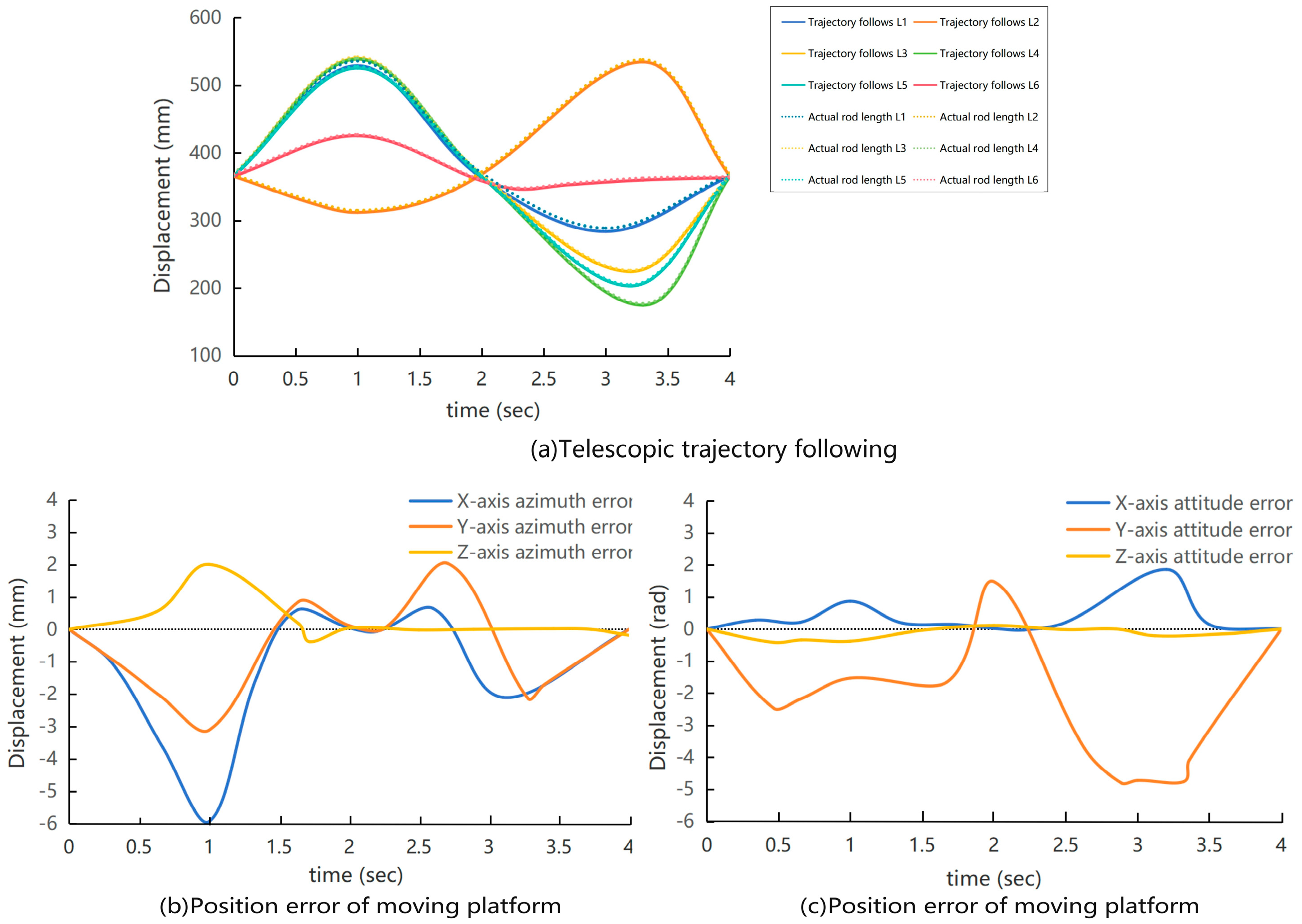
2.5. Kinematics Simulation

Firstly, based on the theoretical analysis results of kinematic spatial posture position coordinates and the parameters of the Stewart parallel lifting platform, a robust adaptive PD (Proportional-Derivative) algorithm is employed to compensate for the platform’s dynamic uncertainties for conducting simulation of tracking the extension trajectory of the lifting mechanism driven by the drive motor [45]. This study utilizes MATLAB R2021b-Simulink for a three-dimensional mechanical model motion simulation, which provides a rich library of functions and toolboxes to assist users in various tasks such as engineering simulation analysis, simulation training, seamless integration with other software for simulation and data analysis, etc. [46]. This research employs the SimMechanics submodule within MATLAB R2021b-Simulink for a kinematic simulation, achieving model motion by defining local coordinate systems and establishing complete motion constraints [47]. The SimMechanics model of a parallel platform consists of multiple rigid bodies connected by joints. Each rigid body represents a segment of the platform, and the joints allow for relative motion between the segments. The model uses actuators to control the motion of the platform and uses sensors to gather data on its position and orientation. The platform is designed to move in a coordinated manner, with each segment following a predetermined trajectory. The parallel platform visualization simulation model is built using SimMechanics, as shown in Figure 7, to display real-time parallel platform trajectory control.
Next, a 6-DOF Stewart parallel lifting platform mechanism and robust adaptive PD control model are constructed using MATLAB-Simulink for a simulation [48]. The extension–retraction curve of the lifting mechanism driven by the driving cylinder in the six support chains is shown in Figure 8a. From the graph, it can be observed that the maximum extension length of the driving cylinder for the lifting mechanism is 173 mm, and the maximum retraction length is 191 mm.
Finally, from the aforementioned Figure 8a depicting the extension–retraction trajectory tracking of the lifting mechanism, as well as Figure 8b showing the dynamic platform position error and Figure 8c illustrating the attitude error, it can be observed that during the initial motion stage of the Stewart parallel lifting platform, slight disturbances are present due to the acceleration process. However, the magnitude of these disturbances is minimal, typically within 0.01 mm, indicating that the initial acceleration stage has a minor impact on the motion of the parallel lifting platform during actual operation. Furthermore, from Figure 8b,c, it is evident that the position and attitude errors in various directions on the Stewart dynamic platform are small, fluctuating around zero. The position error ranges within ± 3.1 × 10 3   m m , while the attitude error is within ± 5.3 × 10 3   r a d , demonstrating that the Stewart parallel lifting platform can accurately output the desired trajectory. This indicates the feasibility of this platform mechanism model.

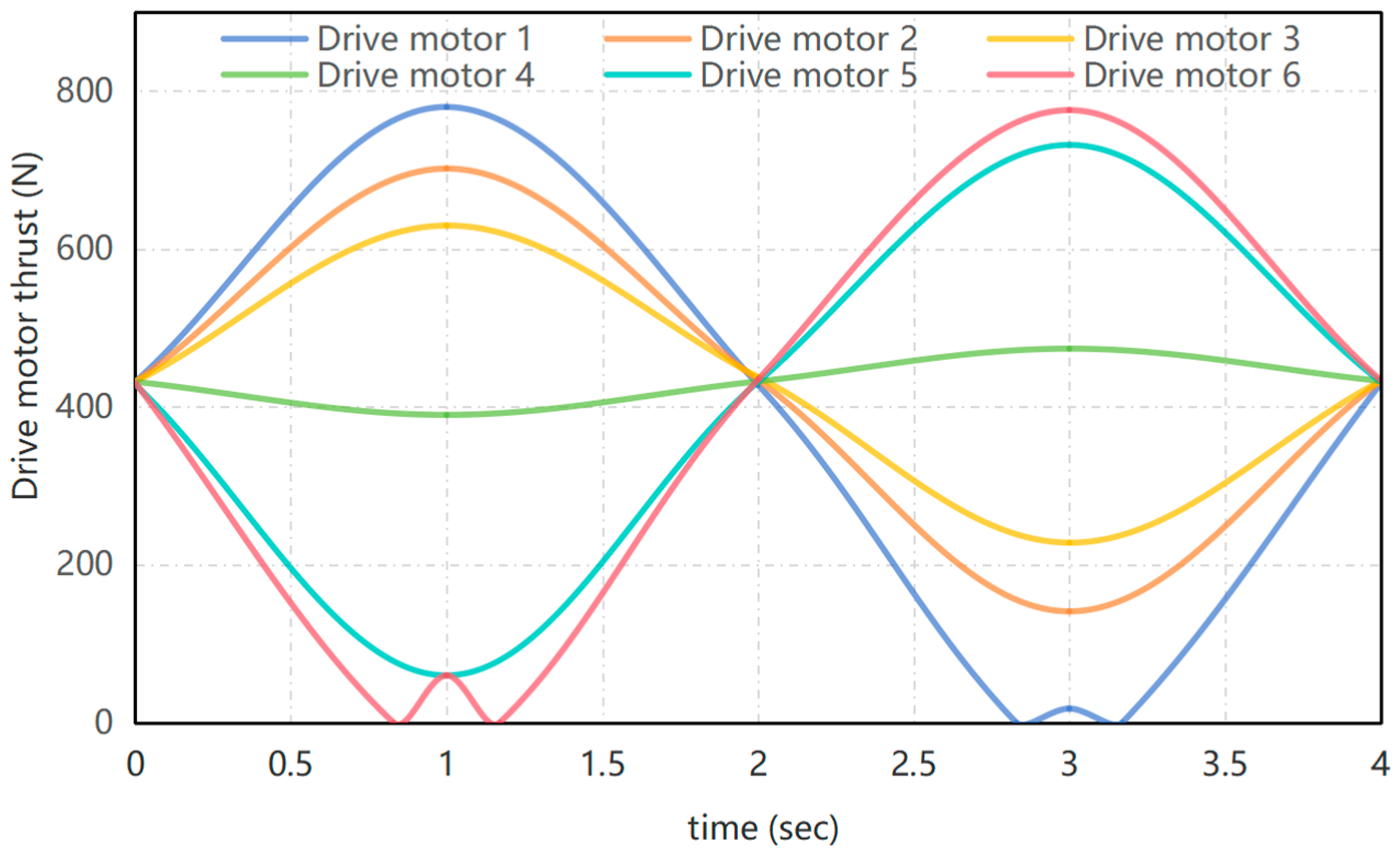
2.6. Dynamic Simulation

This study employs MATLAB-Simulink and ADAMS (Automatic Dynamic Analysis of Mechanical Systems) for joint simulation dynamics research on the thrust of the drive motors in the six-bar linkage. ADAMS 2019 (Ann Arbor, Michigan, United States) is a commercial multi-body dynamics simulation software developed and sold by the MSC Software Corporation [49]. The software simulates the motion and interactions of multi-body systems in a virtual environment, helping users to analyze the dynamic performance of mechanical systems, optimize designs, and solve engineering problems quickly and accurately [50]. Additionally, ADAMS supports various data import and export formats, seamlessly integrating with other engineering software [51]. Therefore, this study first connects MATLAB-Simulink and ADAMS for closed-loop data transmission, and then performs dynamic analysis in ADAMS. MATLAB-Simulink is used to build a model of a Stewart parallel lift platform and a robust adaptive PD control model for simulation. The dynamic model of the extension trajectory of the lifting device driven by the drive motor in the six supporting chains output can be tested in ADAMS without the need for closed-loop control [52,53]. The simulation calculation model has a period of 4 s, a calculation step of 0.005 s, and operates under compound motion conditions. As shown in Figure 9 below, the curve illustrates the variation of thrust for the six drive motors under a load of 60 kg. The results indicate that the trend aligns closely with the specified pose motion process of the dynamic platform, suggesting that the thrust of the six drive motors under a 60 kg load can meet the requirements for the normal operation of the Stewart parallel lifting platform.

3. Results

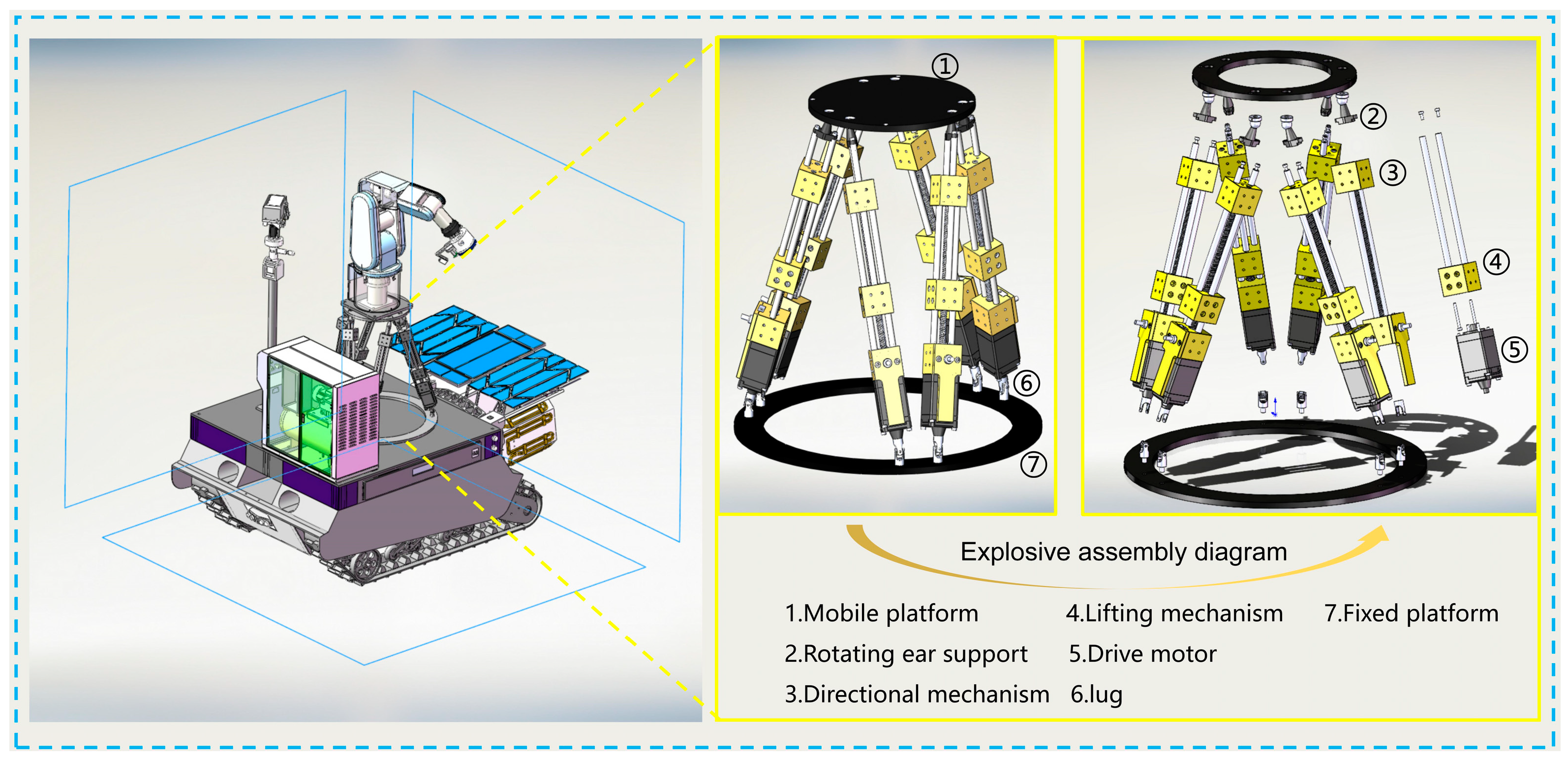
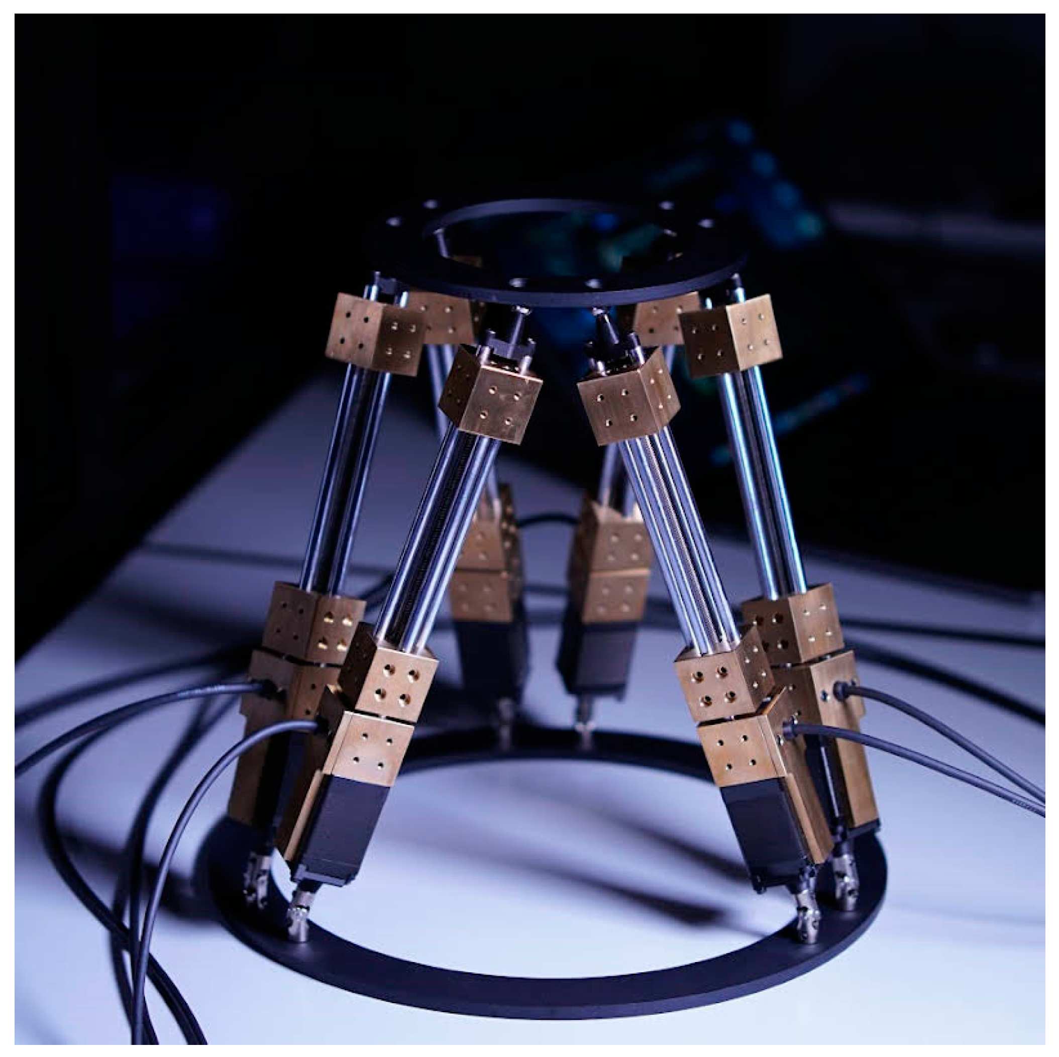
3.1. Mechanical Mechanism

To validate the feasibility of the simulated results mentioned above, the platform mechanism was manufactured according to the designed parameters. The upper platform is connected to the stable lower platform through six branch actuators, and the elevation of the upper platform is achieved by the real-time motion changes of these six actuators. The six branch rods are connected to the upper and lower platforms, respectively, through ball joints and Heim joints. The 6-DOF Stewart parallel lifting platform is shown in Figure 10.
The control system hardware structure connection schematic diagram of the Stewart parallel lifting platform device is shown in Figure 11. The six support chains of the parallel lifting platform use 110BYG350 stepper motors (Hongbaoda Electromechanical Co., Ltd., Shantou, China) and HB3722 three-phase hybrid drivers (Hongbaoda Electromechanical Co., Ltd., Shantou, China) based on DSP control. The rotational motion of the stepper motor is converted to linear motion through the double-line rail-ball screw slide table module composed of an orientation mechanism and lifting mechanism. At the same time, a control system is set up to control the directional extension and contraction movement of the lifting mechanism by controlling the motor torque of the six support chains through pulse control, thereby stabilizing the motion platform. In this study, the MCS53 microcontroller (Hongjing Technology Co., Ltd., Shenzhen, China) is chosen for the programming of relevant programs in the control system, and the AT89S52-24AU 8-bit flash microcontroller chip (Eda Electronics Co., Ltd., Shenzhen, China) is used to control the acceleration, deflection angle, and angular velocity parameters of the six support chains on the X, Y, and Z axes. Additionally, the position measuring components in this research use the FXB-V71 differential transformer-type displacement sensor (Milant Technology Co., Ltd., Shenzhen, China) and the U-shaped photoelectric switch PM-L24 as limit switches (Panasonic Electric Works (China Shanghai) Co., Ltd.) to achieve accurate analysis of linear displacements of each support chain, motion platform position, and the stable maintenance of the control system.

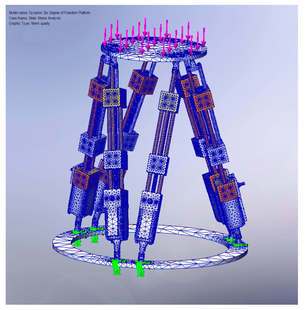
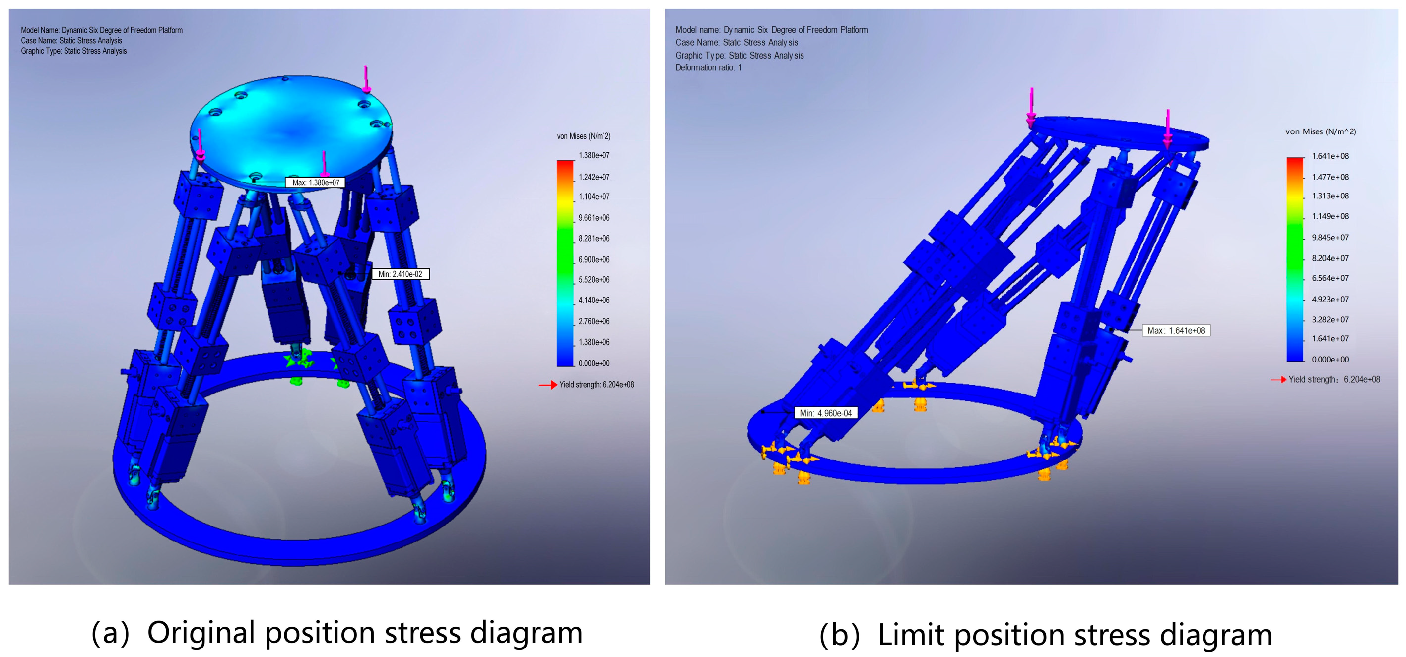
3.2. Finite Element Simulation of the Whole Machine after Loading

By simulating and analyzing the Stewart parallel lifting platform device from its original position to the extreme positions of the platform under a vertical load of 60 kg, the stress values of various components and structures of the entire equipment under the 60 kg load can be obtained. In this study, SolidWorks is chosen to conduct finite element analysis on the solid model using the simulation module. In finite element analysis applications, the type of elements and mesh division determine the computational accuracy of the problem being solved to a certain extent. As shown in Figure 12, the model is divided into a standard mesh for network partitioning, with a total of 5460 nodes and 3429 elements, ensuring high-quality meshing.
Running this mesh quality analysis yields stress plots at the original and extreme positions, as shown in Figure 13a. The yield strength of the Stewart parallel lifting platform is 6.204 × 10 8   M P a , which is significantly higher than the maximum stress values of 1.38 × 10 7   M P a at the original position and 1.641 × 10 8   M P a at the extreme position shown in Figure 13b. The simulation results indicate that the Stewart parallel lifting platform is capable of meeting actual loading requirements.

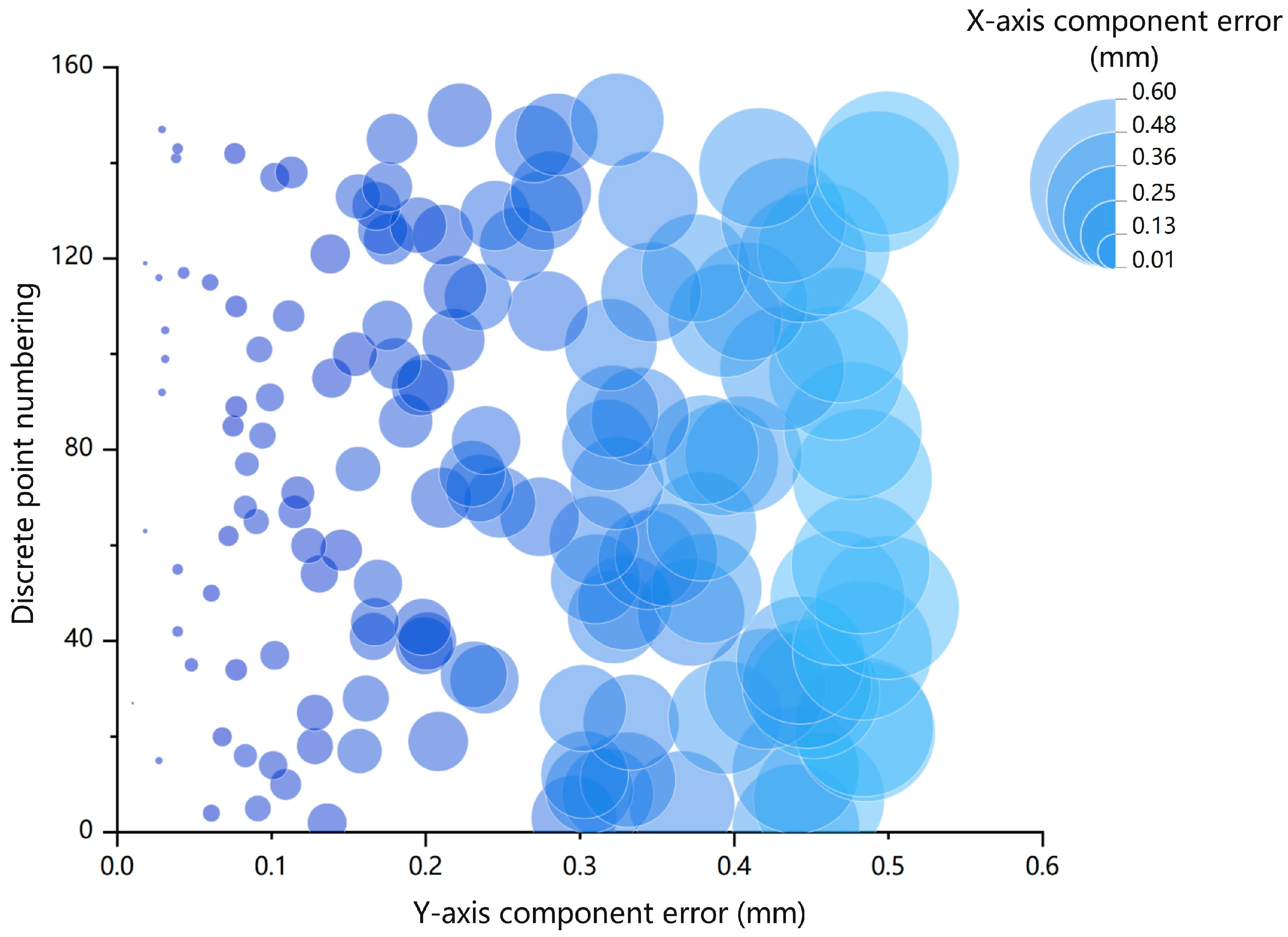
3.3. Experimental Verification

The above-mentioned content of this study has verified that the lifting height and load of the Stewart parallel lifting platform meet its design requirements. Therefore, the experimental validation mainly focused on the stability testing of the moving platform of the Stewart parallel lifting platform. Firstly, theoretical expected trajectories in the form of a “C” shape in JPEG format were generated using motion control functions provided by the motion controller. The theoretical trajectory image containing the “C” shape was then input into MATLAB R2021b software to extract the distribution of feature points, which were used as target positions inputted into the computer. The Stewart parallel lifting platform was connected to the motion control computer via a TCP/IP network interface. Subsequently, the API Tracker3TM laser tracking system was utilized to detect the actual trajectory of the moving platform of the Stewart parallel lifting platform. The experiment involved comparing the theoretical trajectory and real trajectory by calculating the X-axis component error and Y-axis component error for each of the 150 sets of discrete points obtained. The calculation formulas for the errors are as follows:
X = X A X B        ( A , B 1 , 150 )
Y = Y A Y B        ( A , B 1 , 150 )
In the formulas, X represents the X-axis component error, Y represents the Y-axis component error, X A and Y A denote the coordinate values of the discrete points in the theoretical trajectory ( X A , Y A ) , and Y A and Y B represent the coordinate values of the discrete points in the actual trajectory ( X B , Y B ) .
By utilizing MATLAB to read the discrete points of the theoretical trajectory ( X A , Y A ) of the “C” shape on the JPEG image and comparing them with the discrete points coordinates of the actual trajectory ( X B , Y B ) measured by the API Tracker3TM laser tracking system for the moving platform of the parallel lifting platform, the relationship between the expected and actual positions can be determined. As shown in Figure 14, the sizes of the X-axis component error and Y-axis component error are represented by bubble size and horizontal coordinate values, respectively. The X-axis component error and Y-axis component error are well aligned, indicating that the response error of the Stewart parallel lifting platform is within the standard range ± 0.4   m m . The experiment demonstrates the stable motion characteristics of the Stewart parallel lifting platform. As an intelligent agricultural equipment used for assisting in harvesting operations, it can maintain the stability of the harvesting robotic arm during lifting processes and equipment start/stop stages, reducing the risk of swinging during operation and lowering the probability of unexpected accidents.

4. Discussion

This study has designed a Stewart parallel lifting platform with automatic lifting and leveling functions, which is capable of stopping precisely at specified heights to assist in tea-picking operations. The purpose of this is to adapt to the tea-picking robot in order to assist the operation of the picking manipulator. Compared to traditional six-degree-of-freedom parallel platforms, this design also focuses on the stability and accuracy of the platform’s motion posture while meeting the requirements of lifting range and carrying capacity. In addition, the main purpose of the Stewart parallel lifting platform is to optimize the operation space of the picking manipulator on the moving platform, reducing the design complexity of the manipulator, reducing the volume and inertia of the tea-picking manipulator, and assisting the manipulator in quickly moving up and down to the optimal harvesting position. This is in contrast with the low success rate of picking, large damage to tender tea buds, and poor sensitivity and stability resulting from using the Delta parallel manipulator with a shear blade proposed by Hualin Yang and the Mitsubishi RH-6SH5520 four-degree-of-freedom manipulator proposed by Kondo for tea picking. Therefore, the 6-DOF Stewart platform intelligent agricultural device proposed in this study can complement them for auxiliary picking and lifting functions of the picking manipulator. It can meet the requirements of automated operation of the auxiliary tea-picking manipulator. This study provides important solutions for agricultural practitioners and agricultural extension professionals to adopt precision agriculture practices to improve sustainable tea-picking operations.
However, the 6-DOF Stewart parallel lifting platform designed in this study is mainly suitable for specific working conditions and needs to be used in conjunction with a walking base unit that meets specific size and load requirements. Additionally, the platform has not yet been systematically studied with harvesting robotic arms, end effectors, and sensors, which are limitations of this study. Developing an efficient 6-DOF Stewart parallel lift platform is just one of the foundations for future robotic tea harvesting. In future research, our team will delve into the tea harvesting system. In the study of the tea-picking robot’s tea harvesting system, research on the collaborative control of the harvesting robotic arm, end effector, lifting parallel platform, and walking base unit is required. It is necessary to study lightweight design solutions to further enhance the agility and harvesting efficiency of the tea-picking robot, which is the future direction of this team. In addition, our team will also focus on developing other 6-DOF Stewart platforms with broader adaptability and on promoting their applications in other agricultural automation operations, further promoting the development and applications of agricultural robot technology.

5. Conclusions

This study first analyzes the actual planting environment of tea trees and combines it with a kinematic analysis to determine the basic parameters of the parallel lifting platform. A three-dimensional model of the parallel lifting platform is established using SolidWorks, and MATLAB-Simulink is used to simulate the extension amount of the parallel lifting platform. MATLAB-Simulink and ADAMS are connected in a closed loop to perform dynamic simulations to determine the thrust values of the driving motors for each supporting chain. Details of all software abbreviations and terms can be found in Appendix A. The results show that the maximum deflection angle around the X, Y, and Z axes is 10°, the maximum lifting distance is 15 cm, the maximum load is 60 kg, the platform response error is within tolerance, and the stable motion characteristics reach a sub-millimeter level, meeting the requirements for automated assisting in the lifting and harvesting of tea tree mechanical arms.

Author Contributions

Z.W. conceived the overall idea and finalized the draft; C.Y. and R.C. completed the model’s establishment and simulation; the investigation was conducted by Y.C., L.C. and H.L.; experiments were performed by W.Y.; conceptualization was completed by F.Y. and J.T.; writing—review and editing were carried out by B.W.; funding acquisition was also completed by B.W. All authors have read and agreed to the published version of the manuscript.

Funding

This study received funding from various sources, such as the grants for the Development and Demonstration of Intelligent Agriculture Data Sensing Technology and Equipment in Plateau Mountainous Areas (202302AEO9002001), the Study of Yunnan Big Leaf Tea Tree Phenotypic Plasticity Characteristics Selection Mechanism Based on AI-driven Data Fusion (202301ASO70083), and the Smart Tea Industry Technology Task of Menghai County, Yunnan Province (202304B1090013).

Data Availability Statement

The data presented in this study are available upon request from the corresponding author.

Conflicts of Interest

The authors declare no conflicts of interest.

Appendix A

Table A1. Software abbreviation list and term introduction.
NameAbbreviationDescription
SolidWorks 2023SWSolidWorks is an advanced 3D CAD (Computer-Aided Design) software developed by Dassault Systèmes, widely used in the field of engineering design.
Collision Visualization SystemCVSIt is a system used to visualize collision events. It can help users visually observe and analyze the collision situations between different objects in order to carry out data analysis and decision making more effectively.
Proportional-DerivativePDA PD controller combines proportional (P) and derivative (D) control actions. It is a simplified form of a PID controller commonly used in industrial feedback control systems, which calculates the required control signal based on the current state of the control system, error, and rate of change of error.
MATLAB-SimulinkXMATLAB software is a tool developed by MathWorks for mathematical modeling, simulation, and control system design, while Simulink is a module in the MATLAB software.
SimMechanicsXUsers can easily build complex multi-body dynamics models, including mechanical systems, coupled mechanical and electrical systems, and more.
Automatic Dynamic Analysis of Mechanical SystemsADAMSThis software is a simulation software developed by the American company MSC (Ann Arbor, Michigan, United States) Software for conducting dynamic analysis of mechanical systems, capable of quickly and efficiently simulating and analyzing various complex mechanical systems.
SolidWorks-SimulationSW-SimulationSimulation is a module in SolidWorks 2023 software that allows for finite element analysis such as structural, fluid, and thermal analysis. It can validate the performance and durability of products and optimize designs to meet engineering requirements.
Note: The content in Table A1 is from the references in this article. “X” indicates no abbreviation.

References

  1. Wen, X.; Zhang, Z.; Huang, X. Heavy metals in karst tea garden soils under different ecological environments in southwestern China. Trop. Ecol. 2022, 63, 495–505. [Google Scholar] [CrossRef]
  2. Li, W.; Zhang, Q.; Fan, Y.; Cheng, Z.; Lu, X.; Luo, B.; Long, C. Traditional management of ancient Pu’er teagardens in Jingmai Mountains in Yunnan of China, a designated Globally Important Agricultural Heritage Systems site. J. Ethnobiol. Ethnomed. 2023, 19, 26. [Google Scholar] [CrossRef] [PubMed]
  3. Durighello, R.; Luengo, M.; Ono, W.; Han, F.; Zou, Y.; Chen, Y.; Wang, C.; Shimizu, S.; Uesugi, K.; Yamaguchi, K.; et al. Tea Landscapes of Asia: A Thematic Study; ICOMOS: Paris France, 2021. [Google Scholar]
  4. Yang, H.; Chen, L.; Ma, Z.; Chen, M.; Zhong, Y.; Deng, F.; Li, M. Computer vision-based high-quality tea automatic plucking robot using Delta parallel manipulator. Comput. Electron. Agric. 2021, 181, 105946. [Google Scholar] [CrossRef]
  5. Soper, R. How wage structure and crop size negatively impact farmworker livelihoods in monocrop organic production: Interviews with strawberry harvesters in California. Agric. Hum. Values 2020, 37, 325–336. [Google Scholar] [CrossRef]
  6. Hou, R.; Wen, C. Sustainable Tea Garden Ecotourism Based on the Multifunctionality of Organic Agriculture Based on Artificial Intelligence Technology. Mob. Inf. Syst. 2021, 2021, 8696490. [Google Scholar] [CrossRef]
  7. Chen, C.; Lu, J.; Zhou, M.; Yi, J.; Liao, M.; Gao, Z. A YOLOv3-based computer vision system for identification of tea buds and the picking point. Comput. Electron. Agric. 2022, 198, 107116. [Google Scholar] [CrossRef]
  8. Li, Y.; He, L.; Jia, J.; Lv, J.; Chen, J.; Qiao, X.; Wu, C. In-field tea shoot detection and 3D localization using an RGB-D camera. Comput. Electron. Agric. 2021, 185, 106149. [Google Scholar] [CrossRef]
  9. Qi, C.; Gao, J.; Pearson, S.; Harman, H.; Chen, K.; Shu, L. Tea chrysanthemum detection under unstructured environments using the TC-YOLO model. Expert Syst. Appl. 2022, 193, 116473. [Google Scholar] [CrossRef]
  10. Zhang, L.; Zou, L.; Wu, C.; Jia, J.; Chen, J. Method of famous tea sprout identification and segmentation based on improved watershed algorithm. Comput. Electron. Agric. 2021, 184, 106108. [Google Scholar] [CrossRef]
  11. Zhang, L.; Zou, L.; Wu, C.; Chen, J.; Chen, H. Locating Famous Tea’s Picking Point Based on Shi-Tomasi Algorithm. Comput. Mater. Contin. 2021, 69, 16495. [Google Scholar] [CrossRef]
  12. Chen, W.; Zhang, J.; Guo, B.; Wei, Q.; Zhu, Z. An apple detection method based on des-YOLO v4 algorithm for harvesting robots in complex environment. Math. Probl. Eng. 2021, 2021, 7351470. [Google Scholar] [CrossRef]
  13. Mishra, S.; Kumar, C. Compliance modeling of a full 6-DOF series–parallel flexure-based Stewart platform-like micromanipulator. Robotica 2022, 40, 3435–3462. [Google Scholar] [CrossRef]
  14. Luo, N.; Li, Y.; Yang, B.; Liu, B.; Dai, Q. Prediction Model for Tea Polyphenol Content with Deep Features Extracted Using 1D and 2D Convolutional Neural Network. Agriculture 2022, 12, 1299. [Google Scholar] [CrossRef]
  15. Hu, G.; Chen, C.; Chen, J.; Sun, L.; Sugirbay, A.; Chen, Y.; Jin, H.; Zhang, S.; Bu, L. Simplified 4-DOF manipulator for rapid robotic apple harvesting. Comput. Electron. Agric. 2022, 199, 107177. [Google Scholar] [CrossRef]
  16. Xiang, Q.; Cheng, L.; Zhang, R.; Liu, Y.; Wu, Z.; Zhang, X. Tea Polyphenols Prevent and Intervene in COVID-19 through Intestinal Microbiota. Foods 2022, 11, 506. [Google Scholar] [CrossRef]
  17. Nurahmi, L.; Putrayudanto, P.; Wei, G.; Agrawal, S.K. Geometric constraint-based reconfiguration and self-motions of a four-CRU parallel mechanism. J. Mech. Robot. 2021, 13, 021017. [Google Scholar] [CrossRef]
  18. Yang, H.; Chen, L.; Chen, M.; Ma, Z.; Deng, F.; Li, M.; Li, X. Tender tea shoots recognition and positioning for picking robot using improved YOLO-V3 model. IEEE Access 2019, 7, 180998–181011. [Google Scholar] [CrossRef]
  19. Kondo, N.; Nishitsuji, Y.; Ling, P.P.; Ting, K.C. Visual feedback guided robotic cherry tomato harvesting. Trans. ASAE 1996, 39, 2331–2338. [Google Scholar] [CrossRef]
  20. Kang, H.; Chen, C. Fruit detection and segmentation for apple harvesting using visual sensor in orchards. Sensors 2019, 19, 4599. [Google Scholar] [CrossRef]
  21. Xiong, Y.; Peng, C.; Grimstad, L.; From, P.J.; Isler, V. Development and field evaluation of a strawberry harvesting robot with a cable-driven gripper. Comput. Electron. Agric. 2019, 157, 392–402. [Google Scholar] [CrossRef]
  22. Gong, L.; Wang, W.; Wang, T.; Liu, C. Robotic harvesting of the occluded fruits with a precise shape and position reconstruction approach. J. Field Robot. 2022, 39, 69–84. [Google Scholar] [CrossRef]
  23. Cao, P.; Wang, T.; Zhai, L.; Niu, S.; Liu, L.; Shi, Y. Design of 6-DOF Tomato Picking Lifting Platform. Agriculture 2022, 12, 1945. [Google Scholar] [CrossRef]
  24. Yang, J.; Jin, L.; Han, Z.; Zhao, D.; Hu, M. Sensitivity analysis of factors affecting motion reliability of manipulator and fault diagnosis based on kernel principal component analysis. Robotica 2022, 40, 2547–2566. [Google Scholar] [CrossRef]
  25. Wu, L.; Li, X.; Zhong, K.; Li, Z.; Wang, C.; Shi, Y. HCCG: Efficient high compatibility correspondence grouping for 3D object recognition and 6D pose estimation in cluttered scenes. Measurement 2022, 197, 111296. [Google Scholar] [CrossRef]
  26. Lian, B.; Wang, L.; Wang, X. Elastodynamic modeling and parameter sensitivity analysis of a parallel manipulator with articulated traveling plate. Int. J. Adv. Manuf. Technol. 2019, 102, 1583–1599. [Google Scholar] [CrossRef]
  27. Wang, X.; Han, C.; Wu, W.; Xu, J.; Zhang, Q.; Chen, M.; Hu, Z.; Zheng, Z. Fundamental understanding of tea growth and modeling of precise tea shoot picking based on 3-D coordinate instrument. Processes 2021, 9, 1059. [Google Scholar] [CrossRef]
  28. Liu, D.; Arai, S.; Miao, J.; Kinugawa, J.; Wang, Z.; Kosuge, K. Point pair feature-based pose estimation with multiple edge appearance models (PPF-MEAM) for robotic bin picking. Sensors 2018, 18, 2719. [Google Scholar] [CrossRef] [PubMed]
  29. Kuruvilla, J.K.; Seth, A.; Duttagupta, J.; Sharma, S.; Jaiswal, A. Structural Design and Analysis of 6-DOF Cylindrical Robotic Manipulators for Automated Agriculture. In Precision Agriculture for Sustainability; Springer: Berlin/Heidelberg, Germany, 2024; pp. 147–168. [Google Scholar]
  30. Concepcion, R., II; Lauguico, S.; Valenzuela, I.; Bandala, A.; Dadios, E. Denavit-Hartenberg-based Analytic Kinematics and Modeling of 6R Degrees of Freedom Robotic Arm for Smart Farming. J. Comput. Innov. Eng. Appl. 2021, 5, 1–7. [Google Scholar]
  31. Iqbal, J.; Islam, R.U.; Khan, H. Modeling and analysis of a 6 DOF robotic arm manipulator. Can. J. Electr. Electron. Eng. 2012, 3, 300–306. [Google Scholar]
  32. Sundermeyer, M.; Mousavian, A.; Triebel, R.; Fox, D. Contact-graspnet: Efficient 6-dof grasp generation in cluttered scenes. In Proceedings of the 2021 IEEE International Conference on Robotics and Automation (ICRA), Xi’an, China, 5 June 2021; pp. 13438–13444. [Google Scholar]
  33. Taghizadeh, M.; Yarmohammadi, M. Development of a self-tuning PID controller on hydraulically actuated stewart platform stabilizer with base excitation. Int. J. Control. Autom. Syst. 2018, 16, 2990–2999. [Google Scholar] [CrossRef]
  34. Wang, C.; Wang, C.; Wang, L.; Wang, J.; Liao, J.; Li, Y.; Lan, Y. A Lightweight Cherry Tomato Maturity Real-Time Detection Algorithm Based on Improved YOLOV5n. Agronomy 2023, 13, 2106. [Google Scholar] [CrossRef]
  35. Tripodo, C.; Lorenzi, S.; Cammi, A.; Miccichè, G. Object-oriented modeling, simulation and control of a 6-DoF parallel kinematic manipulator for remote handling in DONES facility. Fusion Eng. Des. 2022, 184, 113304. [Google Scholar] [CrossRef]
  36. Jang, T.; Lim, B.; Kim, M. The canonical stewart platform as a six DOF pose sensor for automotive applications. J. Mech. Sci. Technol. 2018, 32, 5553–5561. [Google Scholar] [CrossRef]
  37. Xu, W.; Zhao, L.; Li, J.; Shang, S.; Ding, X.; Wang, T. Detection and classification of tea buds based on deep learning. Comput. Electron. Agric. 2022, 192, 106547. [Google Scholar] [CrossRef]
  38. Tanaka, Y. Active vibration compensator on moving vessel by hydraulic parallel mechanism. Int. J. Hydromechatron. 2018, 1, 350–359. [Google Scholar] [CrossRef]
  39. Zhang, L.; Zong, X.; Tang, Y.; Chen, X.; Feng, J.; Yuan, X. Modal and natural frequency sensitivity analysis of electrohydraulic stewart platform. Shock Vib. 2021, 2021, 5587282. [Google Scholar] [CrossRef]
  40. Xie, Z.; Li, G.; Liu, G.; Zhao, J. Optimal design of a Stewart platform using the global transmission index under determinate constraint of workspace. Adv. Mech. Eng. 2017, 9, 1687814017720880. [Google Scholar] [CrossRef]
  41. Kenfack Essougong, U.P.; Slingerland, M.; Mathé, S.; Giller, K.E.; Leeuwis, C. Farmers’ access, demand, and satisfaction with innovation support services and their determinants: The case of the cocoa sector in Central Cameroon. J. Agric. Educ. Ext. 2023, 1–31. [Google Scholar] [CrossRef]
  42. Lee, C.L.; Strong, R.; Briers, G.; Murphrey, T.; Rajan, N.; Rampold, S. A correlational study of two US state Extension professionals’ behavioral intentions to improve sustainable food chains through precision farming practices. Foods 2023, 12, 2208. [Google Scholar] [CrossRef]
  43. Seth, A.; Kuruvilla, J.K.; Sharma, S.; Duttagupta, J.; Jaiswal, A. Design and simulation of 6-DOF cylindrical robotic manipulator using finite element analysis. Mater. Today Proc. 2022, 62, 1521–1525. [Google Scholar] [CrossRef]
  44. Ariffin, M.A.K.; Kiong, S.C. Design and Development Small Scale Packaging Machine for Tea Bags. J. Des. Sustain. Environ. 2024, 6, 40–43. [Google Scholar]
  45. Wu, Y.; Yu, K.; Jiao, J.; Cao, D.; Chi, W.; Tang, J. Dynamic isotropy design and analysis of a six-DOF active micro-vibration isolation manipulator on satellites. Robot. Comput.-Integr. Manuf. 2018, 49, 408–425. [Google Scholar] [CrossRef]
  46. Wu, Y.; Yu, K.; Jiao, J.; Zhao, R. Dynamic modeling and robust nonlinear control of a six-DOF active micro-vibration isolation manipulator with parameter uncertainties. Mech. Mach. Theory 2015, 92, 407–435. [Google Scholar] [CrossRef]
  47. Patra, S.; Sarkhel, P.; Hui, N.B.; Banerjee, N. Modelling and Simulation of a Fishing Rod (Flexible Link) Using Simmechanics. J. Eur. Systèmes Autom. 2020, 53, 451–460. [Google Scholar] [CrossRef]
  48. Li, Y.; Ang, K.H.; Chong, G.C. PID control system analysis and design. IEEE Control. Syst. Mag. 2006, 26, 32–41. [Google Scholar]
  49. Afkar, A.; Mahmoodi-Kaleibar, M.; Paykani, A. Geometry optimization of double wishbone suspension system via genetic algorithm for handling improvement. J. Vibroeng. 2012, 14, 827–837. [Google Scholar]
  50. Xu, Y.; Liao, H.; Liu, L.; Wang, Y. Modeling and robust H-infinite control of a novel non-contact ultra-quiet Stewart spacecraft. Acta Astronaut. 2015, 107, 274–289. [Google Scholar] [CrossRef]
  51. Nair, A.S.; Ezhilarasi, D. Performance analysis of super twisting sliding mode controller by ADAMS–MATLAB co-simulation in lower extremity exoskeleton. Int. J. Precis. Eng. Manuf.-Green Technol. 2020, 7, 743–754. [Google Scholar] [CrossRef]
  52. Affi, Z.; Romdhane, L. ADAMS/Simulink interface for dynamic modeling and control of closed loop mechanisms. In Proceedings of the 7th WSEAS International Conference on Automatic Control, Modeling and Simulation, Prague, Czech Republic, 13–15 March 2005; pp. 13–15. [Google Scholar]
  53. Shi, P.; Zhao, Q.; Wang, K.; Zhang, R.; Xiao, P. Simulation and verification analysis of the ride comfort of an in-wheel motor-driven electric vehicle based on a combination of ADAMS and MATLAB. Int. J. Model. Simul. Sci. Comput. 2022, 13, 2250002. [Google Scholar] [CrossRef]
Figure 1. Illustration of the planting pattern of small arbor Yunnan large-leaf tea trees.
Agronomy 14 00844 g001
Figure 2. Schematic diagram of the movement mode and overall structure of the tea picking robot.
Agronomy 14 00844 g002
Figure 3. Schematic diagram of Stewart parallel lifting platform. In (a): L1~L6 represents the driving branched chain, O1-X1Y1Z1 is the mobile platform connected coordinate system, and O2-X2Y2Z2 is the fixed platform inertial coordinate system. In (b): Q1~Q6 represents the hinge point of the mobile platform, W1~W6 represents the hinge point of the fixed platform, and RQ and RW represent the radius of mobile platform and fixed platform, respectively.
Agronomy 14 00844 g003
Figure 4. Stewart parallel lifting platform three-dimensional model and explosive assembly diagram.
Agronomy 14 00844 g004
Figure 5. Sixteen extreme position postures.
Agronomy 14 00844 g005
Figure 6. Rotation of spatial coordinates.
Agronomy 14 00844 g006
Figure 7. Stewart parallel lift platform SimMechanics model.
Agronomy 14 00844 g007
Figure 8. Kinematics simulation results.
Agronomy 14 00844 g008
Figure 9. Thrust change curve of driving motor.
Agronomy 14 00844 g009
Figure 10. Stewart parallel lifting platform physical map.
Agronomy 14 00844 g010
Figure 11. Block diagram of hardware structure of control system.
Agronomy 14 00844 g011
Figure 12. Grid quality map. In the figure, the pink arrow represents a 60 kg force applied vertically downwards on the East platform; the blue represents the unit network division of the entire machine; and the green represents the entire machine fixed on the static platform.
Agronomy 14 00844 g012
Figure 13. Finite element analysis diagram.
Agronomy 14 00844 g013
Figure 14. Moving platform component error diagram.
Agronomy 14 00844 g014
Table 1. Tea tree physical parameters.
Tree SpeciesR/mZ/mY/mX/m
Yunnan large leaf variety small tree-type tea tree0.8–1.01.5–1.80.6–1.01.1–1.5
Disclaimer/Publisher’s Note: The statements, opinions and data contained in all publications are solely those of the individual author(s) and contributor(s) and not of MDPI and/or the editor(s). MDPI and/or the editor(s) disclaim responsibility for any injury to people or property resulting from any ideas, methods, instructions or products referred to in the content.

