
Optimization of Vibrating Mesh Nebulizer Air Inlet Structure for Pulmonary Drug Delivery

1
School of Energy and Mechanical Engineering, Nanjing Normal University, Nanjing 210042, China
2
Hefei Leecan Pharmaceutical Co., Ltd., Hefei 230000, China
3
Chongqing Tsingshan Industry Co., Ltd., Chongqing 402761, China
*
Author to whom correspondence should be addressed.
Atmosphere 2023, 14(10), 1509; https://doi.org/10.3390/atmos14101509
Submission received: 22 August 2023
/
Revised: 26 September 2023
/
Accepted: 28 September 2023
/
Published: 29 September 2023
(This article belongs to the Special Issue Numerical Simulation of Aerosol Microphysical Processes)
Abstract
:The vibrating mesh nebulizer (VMN) has gained popularity for its compactness and noiselessness. This study investigates the impact of different air inlet structures on the deposition fraction (DF) of droplets generated by VMNs in an idealized mouth–throat (MT) airway model. Three homemade VMNs with semi-circular inlet, symmetrical four-inlet, and multiple-orifice inlet structures were evaluated through simulations and experiments. The changes in droplet DF of 0.9% w/v concentration of nebulized sodium chloride (NaCl) droplets as a function of inertial parameters were acquired under different inhalation flow conditions. Additionally, flow field distributions in models with different inlet structures were analyzed at a steady inspiratory flow rate of 15 L/min. The results indicate that optimizing the VMN’s air inlet structure significantly enhances droplet delivery efficiency. The multiple–orifice inlet structure outperformed the other designs, directing the airflow from the inlet position to the center of the mouthpiece and then into the oral cavity, achieving a DF of up to 20% at an inhalation flow rate of 15 L/min. The region of high airflow velocity between the mouthpiece and oral cavity proved to be a favorable VMN inlet optimization, reducing direct droplet–wall collisions and improving delivery efficiency. These findings offer insights for VMN design and optimization to enhance pulmonary drug delivery effectiveness and therapeutic outcomes.
1. Introduction
Nebulization therapy is a treatment modality for respiratory diseases, wherein therapeutic aerosols for pulmonary application are generated by a nebulizer device [1,2]. With the continuous improvement of manufacturing technology, the vibrating mesh nebulizer (VMN) is considered to be an effective method for administering inhaled drugs and overcomes the main limitations of jet and ultrasonic nebulizers [1,3,4]. The vibrating mesh in the nebulizer contains a piezoelectric element that is fixed at the bottom of the nebulizer chamber and vibrates when an electric current is applied [5,6]. The respirable solution in the nebulizer chamber is converted into fine droplets that are directed towards the patient through the upward and downward movement of the vibrating plate [3]. Compared to the jet nebulizer, the VMN can result in a higher inhaled dose and lower residual dose during aerosol delivery, while also being lightweight and portable [7,8]. Pitance et al. [9] compared drug inhalation quality and urine drug concentration using three different nebulization delivery devices. The results showed that the mesh nebulizer delivered a higher drug dose and lung deposition than the compressed-air nebulizer. Moody et al. [10] discovered that the VMN was superior in treating pediatric asthma compared to traditional jet nebulizers, leading to a significant reduction in the incidence rate among children.
Thorough studies into the deposition mechanism of aerosols can offer improved design solutions for inhalation therapy. Cheng et al. [11] measured aerosol deposition in the oropharyngeal region at different diameters and flow velocities. They discovered that inertial impaction was the primary deposition mechanism, with both mean and minimum particle diameters being significant influencing factors. Lin et al. [12] studied the factors and patterns affecting particle deposition in the oropharyngeal region using Di-Ethyl-Hexyl-Sebacate (DEHS) droplets. The results showed that reducing the inlet diameter and increasing the inhalation flow rate correspondingly increased particle deposition for particles with diameters of 4 and 8 μm but had no effect on 2 μm particles. Chen et al. [13] simulated deposition due to gravitational sedimentation and inertial impaction in a triple bifurcation airway of 1~7 μm particles. The findings show that large particles with diameters of 5 μm and 7 μm exhibit minimal deposition efficiency due to gravity. Additionally, the deposition efficiency of small particles decreases with increasing Stokes number, indicating that sedimentation is the dominant deposition mechanism. The research by Kleinstreuer and Zhang suggests that micrometer-sized particle deposition in the oral airway primarily occurs in the tongue region of the mouth, the outer curvature of the pharynx, the glottis, and the upstream region of the trachea [14]. Feng et al. [15] proposed a comprehensive computational fluid droplet dynamics model to predict the transport, phase change, and deposition of multi-component droplet–vapor interaction in the human upper respiratory airway model. Golshahi et al. [16] quantified the deposition of micrometer-sized aerosols in realistic oropharyngeal airway replicas of children aged 6~14 years old.
Researchers have proposed various design solutions to enhance drug delivery with inhalation devices. Zhang et al. [17] developed an active and multi-dose dry powder inhaler, which could efficiently deliver a small quantity of fine drug particles into the lungs with high fine particle fraction. Kakada et al. [18] proposed a design solution for optimizing pressurized metered dose inhalers (pMDI) through combining a vortex nozzle with a dispersion nozzle to reduce the spray’s exit rate and thus optimize the deep lung deposition of drug particles. Gong and Fu proposed a novel spray nebulizer and studied the effects of structural parameters and liquid viscosity on its flow characteristics through experimental research [19]. Selvam et al. [20] studied the effects of different geometric structures and film properties on the aerosolization performance of dry powder inhaler (DPI) devices. The findings showed that reducing the device’s inlet diameter and increasing the thickness of the drug-coated film inside the device could optimize the DPI device’s design, leading to improved dispersion of the drug aerosol and better nebulization efficiency. Hu et al. [21] measured lung deposition of different drugs and nebulizer combinations under different breathing patterns and found that a “slow deep breathing” pattern resulted in more drugs delivered into the lung. Howe et al. [22] designed a jet platform for infant inhalation therapy, which is driven by a positive-pressure air source with different parameters. Multiple air-jet DPI designs were designed to be combined with the air sources, aiming to improve lung delivery efficiency. Zhang et al. [23] developed a design based on the modular modified Sympatec HELOS that integrates an inhaler device, artificial throat, and pre-separator with the device. The dispersion, fluidization, transport, separation, and deposition processes of the dry powder inhaler were studied at different inspiratory flows, monitoring the real-time pulmonary drug delivery process. This study provides guidance for the design and optimization of carrier-based dry powder inhalers. Talaat et al. [24] developed a mass-based dosimetry method for evaluating metered-dose inhaler (MDI) drug delivery, showing the important of appropriate deposition quantification methods for reliable MDI drug delivery predictions in the human respiratory tract.
Modifications to the structure of the inhalation device can affect the airflow patterns and the efficiency of drug delivery to the lungs. A series of studies have delved into the intricate details of pressurized metered-dose inhalers (pMDIs) with the aim of enhancing drug delivery efficiency. Kleinstreuer et al. [25] examined pMDIs, exploring the influence of device propellants, nozzle diameters, and spacers on drug delivery to the lungs. Si et al. [26] extended this exploration through investigating the effects of MDI canister-holder guiding vanes and orifice airflow on inhalation dosimetry, recognizing their potential long-lasting impact on aerosol penetration into smaller airways. A study by Leung et al. [27] has elucidated the different effects and the mechanism of the aerosolization of varied dry powder inhaler formulations due to the grid design, indicating that the increased retention of drugs on the mouthpiece due to increased powder–mouthpiece impaction is offset by an increase in drug detachment from carriers. Experimental and simulation studies have shown that optimizing the structure of inhalation devices is crucial for drug delivery. However, optimizing lung drug delivery remains a challenging and important research topic due to complex aerosol deposition mechanisms and the human lung airway’s intricate geometry. This study aims to provide more effective design methods for optimizing nebulizer structures.
Simulation studies of the nebulizer structure can help optimize the design, gain a deeper understanding of the mechanism, and optimize parameters. Fossat et al. [28] investigated the mechanical behavior of an ultrasonic mesh atomizer using four analytical models. The models considered modal analysis, kinematics of perforations, and the effects of a stepped plate and piezoelectric ring, and the models’ validity was confirmed through finite-element frequency domain computations. The study provided valuable insights into the design and operation of the atomizer. Xi et al. [29] developed a practical technique for visualizing nebulized aerosol deposition in a human airway model. They used a combination of 3D-printed airway replicas, Sar-Gel visualization, and computational simulations. Combining experiments and simulations in research can validate the accuracy of the model and provide more comprehensive results.
To investigate the impact of different air inlet structures on drug delivery efficiency, this study designed three structures. Through simulations and experiments conducted in an idealized MT model, the study analyzed the influence of inspiratory flow rate, droplet diameter, and air inlet structures on the deposition fraction (DF) of droplets generated by VMNs.
2. Methods
2.1. Experimental Setup
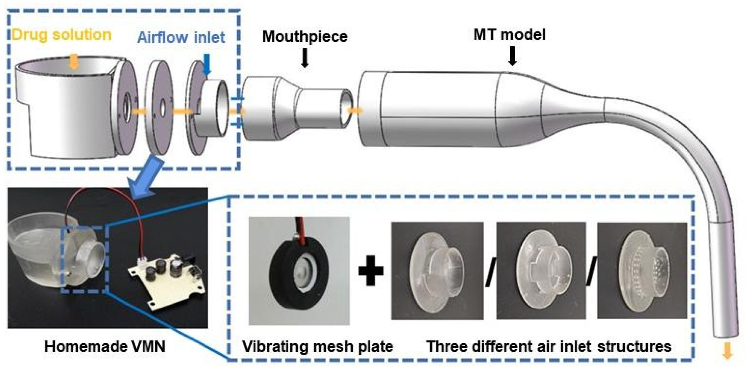
The study was conducted in an ISO 4 cleanroom within the laboratory, allowing precise control over environmental variables. The laboratory was maintained at a constant temperature of 26.5 °C ± 1 °C and a relative humidity of 50% ± 2%. The experimental setup used in this study is presented in Figure 1. The homemade VMN outlet was connected to an idealized MT model, positioned horizontally and accessed through a mouthpiece. An airflow carrying droplets entered the MT model, where some droplets were deposited on its surface, while others were captured with air through a bubble absorption tube, prefilter, and membrane filter. The bubble absorption tube, filled with deionized water (Nandye Co., Wenzhou, China), captured most of the droplets that leaked out of the MT model. The prefilter intercepted large droplets generated by bubbles bursting in the absorption tube, and the remaining droplets were collected using a membrane filter with a pore size of 0.1 μm. The airflow was regulated using a glass rotor flowmeter (10–100 L/min, ±4%, LZM-6T, Senlod Co., Ltd., Nanjing, China) to ensure stability during the experiments. The homemade VMN setup used in the experiment mainly consists of a reservoir, a vibrating mesh plate, an air inlet structure, a mouthpiece, and a driver circuit board, as illustrated in Figure 2.
Test droplets were generated from a 0.9% w/v sodium chloride (NaCl) solution, and three different homemade VMN inlet structures were evaluated: (1) a semi-circular structure modeled based on a commercial VMN (HL100A, Yuwell Co., Danyang, China); (2) a symmetrical four-inlet structure; and (3) a multiple-orifice structure. The three different air inlet structures were 3D-printed (Form3, Formlabs, Somerville, Medford, OR, USA) as shown in Figure 3a–c. The semi-circular structure consisted of a 3 mm wide opening on the upper half of the circular pipe wall at the nebulizer outlet. The symmetrical four-inlet structure had the same opening area as the semi-circular structure and consisted of four inlet structures evenly distributed in the four directions (up, down, left, and right) on the circular tube wall of the VMN. The multiple-orifice structure comprised two rings of small orifices uniformly distributed on the circular tube wall at the VMN outlet. The diameter of each orifice was 1 mm, and the total area equaled that of the previous two structures.
The droplet size distribution of a 0.9% w/v NaCl solution nebulized using the homemade VMNs was measured using the light scattering method (Spraylink, Zhuhai Optical Instrument Co., Ltd., Zhuhai, China). Since the nebulizer plate remains the same in all tested VMNs, the droplet size distribution is consistent across different inlet structures. After three measurements, the mass median aerodynamic diameter (MMAD) of the droplets generated by the VMN in this experiment was 5.019 micrometers, with a geometric standard deviation (GSD) of 1.495. The diameter measurement results were obtained through averaging 10 samples of data taken within 30 s.
The idealized MT model used in this experiment was proposed by Zhang et al. [30] and has been demonstrated to accurately replicate the deposition characteristics of a real human MT airway. The model, as shown in Figure 4, comprises a straight section of inlet, a constriction nozzle of appropriate length, and a 90° bend. The oral inlet diameter is 30 mm, and the throat outlet diameter is 8.5 mm. The mouth section is 50 mm in length, while the nozzle that connects it to the bend measures 45 mm. The bend has a curvature radius of 50 mm. The MT model was divided into two symmetrical halves to facilitate the cleaning of the inner surface following the deposition experiment.
2.2. In Vitro Droplet Deposition Test
During the experiment, the experimental system was assembled according to the structure shown in Figure 1. The vacuum pump was turned on to adjust the flow meter until the flow rate stabilized, and then the VMN was turned on. The droplets generated by the VMN passed through the experimental system with the airflow. Some droplets were deposited in the MT model, while others were captured by the filtration devices. Each droplet deposition experiment lasted approximately 5 min. After the deposition experiments, all components were disassembled and subjected to ultrasonic cleaning. The rinsing solution from each part was collected, and its chloride ion concentration was measured to determine the mass of deposited droplets in each component and subsequently calculate the DF. The measurement precision of the experiment was confirmed in the preliminary stage [31,32], where the error between the collected droplet mass and the total nebulization mass was less than 10%. The deposition experiments for the three inlet structures were conducted at inhalation flow rates of 15, 22.5, 30, 45, and 60 L/min. Each experimental condition was repeated three times to avoid errors.
2.3. Numerical Methods
Due to the complex geometric model of the air inlet structure of the nebulizer, diffusion was prone to occur at the mouthpiece outlet, and the contraction of the cross-sectional area at the throat could result in an increase in airflow velocity, leading to the transition from laminar to turbulent flow and boundary layer separation. Therefore, a turbulence model capable of accurately solving such transition and separation phenomena is crucial for subsequent simulation studies. Menter et al. proposed the Transition SST model, which has been proven to better solve transition and separation phenomena than traditional RANS models [33]. Zhang and Kleinstreuer also applied this turbulence model in a simulation study of the human respiratory tract [34]. Hence, this turbulence model was used to simulate the transition from laminar to turbulent flow and boundary layer separation that occurred in the air inlet structure model connected to the MT model. The equations for the Transition SST model are given below [35]:
where is the fluid density, is the distance in the direction, and is the mean velocity in the direction.
where p is the gas pressure, is the turbulent dynamic viscosity, is the Kronecker function ( when = ; otherwise), and is the turbulent velocity fluctuation in the direction.
where is the turbulent kinetic energy, is the modification term based on the standard SST model for turbulent kinetic energy production, is the modification term based on the standard SST model for turbulent kinetic energy dissipation, is the turbulent dynamic viscosity, and is the turbulent Prandtl number for turbulent kinetic energy.
where is the turbulent dissipation rate, is the production term for turbulent dissipation rate, and is the dissipation term for turbulent dissipation rate.
where and are the production terms for the intermittency factor, and and are the dissipation terms for the intermittency factor .
where is the production term for the transition momentum thickness Reynolds number.
2.4. Geometries for Simulations
According to the experimental design, three types of inlet structure models were constructed and connected to the mouthpiece and subsequently linked to the respiratory tract model, as shown in Figure 5a–c, where the blue regions represent the air inlets.
Firstly, the mesh independence test was conducted for the geometry of the semi-circular inlet. A monitoring line M-M′ (as shown in Figure 6) was selected in the MT model, and the non-dimensional velocity distribution along this line was compared under different mesh sizes with five boundary layers, as shown in Figure 7. The results with 14.8 million meshes were used as the baseline, and it was found that the results with 2.64 million meshes had an error of less than 5%. Therefore, the model with 2.64 million meshes was used for subsequent simulation analysis. The same mesh independence test was performed for the symmetrical four-inlet and multiple-orifice models, and finally, 2.7 million meshes and 2.68 million meshes were used for the subsequent simulations of the symmetrical four-inlet and multiple-orifice models, respectively.
2.5. Simulation Setup
To study the transport of inhaled drug particles within the MT model, simulations were conducted to observe the flow field distribution under a steady inspiratory flow rate of 15 L/min. The pressure-based solver was used during the simulation process, and the SIMPLE algorithm was employed. The second-order upwind scheme was used for discretization, and convergence of the airflow field calculation was considered to be achieved when the dimensionless residual was less than 10−3. At the inlet of the VMN, a pressure-inlet condition was applied, and at the outlet of the MT model, a pressure-outlet condition was applied to simulate the inspiratory flow caused by lung expansion.
2.6. DF
The DF is a quantitative measure of droplet deposition in the human airway, and it is defined as:
where is the mass of droplets deposited in the mouthpiece and MT model, and is the total mass of droplets deposited in the bubble absorption tube, prefilter, and membrane filter.
3. Results and Discussion
3.1. Numerical Simulation of Flow Field Distribution
Figure 8 shows the velocity distribution on the plane and eight cross-sections for different air inlet structure models at an inspiratory flow rate of 15 L/min. Thehe semi-circular inlet, symmetrical four-inlet, and multiple-orifice inlet structures were designated VMN1, VMN2, and VMN3, respectively. As shown in Figure 8a,b, for the semi-circular structure, due to the non-centrally symmetrical design of the inlet, the airflow enters the mouthpiece vertically from the top and forms two symmetric vortices after impacting the lower sidewall of the mouthpiece. These vortices then move along the left and right sidewalls of the mouthpiece, meet above the mouthpiece, and then move downward. As the airflow leaves the mouthpiece, due to the higher velocity at the edge of the mouthpiece, the airflow decelerates rapidly and diffuses at the rear of the oral cavity. However, it should be noted that the faster-velocity region at cross-section 5 is concentrated in the middle plane, not at the centerline of the flow. This indicates that the flow is not fully developed yet, and there is relatively strong secondary flow in the pharyngeal region compared to Figure 8d, f, making it more likely for droplets to deposit on the respiratory tract wall. For the pharyngeal section of the MT model under the three inlet structure models, the velocity distributions at cross-sections 6, 7, and 8 are similar, with the high-velocity region located on the outside of the bend.
In Figure 8c, the symmetrical four-inlet structure shows improved flow characteristics compared to the semi-circular structure, and there is no obvious downward flow. However, in Figure 8d, at cross-section 1, the airflow collision results in an X-shaped high-velocity region at cross-section 2, indicating that the airflow is concentrated in the center of the horizontal oral structure but with strong secondary flow toward the oblique upper and lower walls of the mouthpiece. This may also increase the DF of droplets. At cross-sections 3 and 4, the airflow inside the mouthpiece is relatively uniform with slightly higher velocities in the middle. At cross-section 5, the central velocity is also higher, and the diffusion of air at the rear of the oral cavity is not significant.
The multiple-orifice inlet structure exhibits the best flow characteristics. In Figure 8e, the velocity distribution on the middle plane shows that the airflow in the oral cavity is almost entirely concentrated in the central region with weak diffusion towards the upper and lower sides. In Figure 8f, at cross-section 1, the multiple orifices converge at the back of the nebulizer plate, and at cross-section 2, a nearly perfect circular high-velocity region is formed. At cross-section 3 in the mouthpiece area, there is a slight horizontal diffusion, but the extent of diffusion is lower than that of the symmetrical four-inlet structure in Figure 8d. Subsequent cross-sections 4 and 5 show more concentrated velocity centers compared to the symmetrical four-inlet structure.
It can be concluded that the multiple-orifice inlet structure directs the airflow from the inlet position to the center of the mouthpiece and then into the oral cavity, avoiding the direct impact on the walls as seen in the semi-circular structure. Compared to the symmetrical four-inlet structure, it reduces the diffusion of airflow towards the surrounding area, thus reducing the deposition of droplets in the oral cavity under the influence of secondary flow.
3.2. Experimental Study of DFs
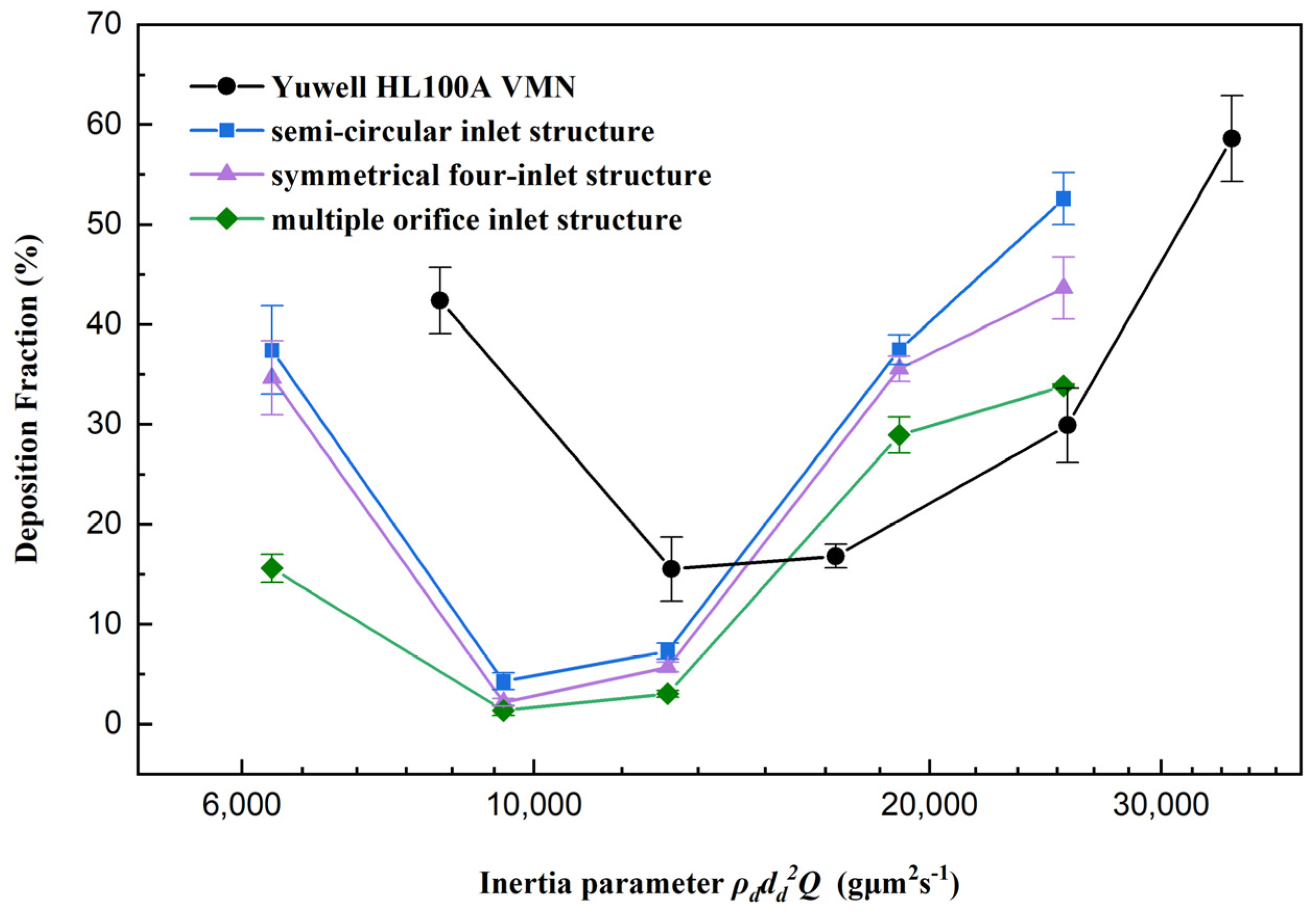
Figure 9 shows the DF of droplets generated by three different inlet structures of the VMN in the MT model as a function of the inertial parameter , along with the results from preliminary tests with a commercial VMN. The experimental results are represented by black circles for the Yuwell HL100A VMN, blue squares for nebulizers with a semi-circular air inlet structure, purple triangles for symmetrical four-inlet structures, and green diamonds for multiple-orifice air inlet structures.
As shown in Figure 9, the DF results of the homemade VMNs with three different inlet structures and the commercial VMN from the preliminary study [31] all exhibit a U-shaped trend. Specifically, when the inhalation flow rate is low, limited droplet evaporation and the influence of gravity settling lead to higher DFs. As the flow rate increases, droplet evaporation becomes more complete, reducing droplet size and enhancing alignment with airflow, resulting in lower DFs. At higher flow rates, almost complete droplet evaporation, combined with increased velocity and inertia, leads to elevated DFs. Further details on these mechanisms can be found in our previous work [36]. Among them, the VMN with the multiple-orifice inlet structure shows the lowest DF in the MT model, indicating the highest efficiency for pulmonary drug delivery.
At an inhalation flow rate of 15 L/min, the DFs of semi-circular inlet and symmetrical four-inlet VMNs are 37.4% and 34.7%, respectively, while the multiple-orifice inlet VMN exhibits only 15.6% deposition. As the inhalation flow rate increases to 22.5 and 30 L/min, the DFs for all VMNs significantly decrease, with values below 10%. When the inhalation flow rate is raised to 45 L/min, the DFs for the three VMNs rise again to 37.5%, 35.6%, and 29.0%, respectively. Further increasing the inhalation flow rate to 60 L/min results in the DFs continuing to increase to 52.6%, 43.6%, and 33.8% for the semi-circular inlet, symmetrical four-inlet, and multiple-orifice inlet structures, respectively. The variations in DFs with inhalation flow rate, initially decreasing and then increasing, have been previously explained in experiments conducted by Xia et al. [31] and Yang et al. [32]. At 15 L/min, the lower inhalation flow rate leads to a relatively larger amount of nebulized droplets, causing some droplets to reach equilibrium with the increased humidity of inhaled air, thereby preventing further evaporation. As the inhalation flow rate increases, the dilution of droplet flow allows for more efficient evaporation. When the airflow velocity increases moderately, the droplet inertia decreases, leading to reduced DFs. However, as the airflow velocity further increases, inertial collisions are intensified, resulting in a rapid increase in DFs at 45 and 60 L/min.
Changes in the VMN inlet structure affect the direction and velocity of airflow in the respiratory tract, thereby influencing the transport and deposition of droplets in the MT model. This suggests that inertial collisions are the primary factor affecting droplet deposition. Compared with the asymmetric semi-circular structure, the multiple-orifice structure makes the flow field distribution more uniform. As a result, the drug carried by the airflow enters the central position of the airway, significantly reducing droplet–wall collisions and improving droplet delivery efficiency.
4. Conclusions
In this study, we investigated the influence of different air inlet structures on the DF of droplets generated by VMNs in an idealized MT airway model, using both simulations and experiments. Three different homemade VMNs with semi-circular inlet, symmetrical four-inlet, and multiple-orifice inlet structures were evaluated. The main findings are as follows:
Optimization of the VMN’s air inlet structure significantly improves the efficiency of droplet delivery. Among the homemade VMNs with different inlet structures, the semi-circular inlet structure showed the lowest DF, with only marginal improvement observed for the symmetrical four-inlet structure. In contrast, the multiple-orifice inlet structure exhibited the best performance. Under the condition of a 15 L/min inhalation flow rate, the optimization of the multiple-orifice inlet structure resulted in a DF of up to 20%. Furthermore, the region of high airflow velocity located between the mouthpiece and oral cavity was found to be a favorable VMN inlet optimization design. The multiple-orifice inlet structure directs the airflow from the inlet position to the center of the mouthpiece and then into the oral cavity, reducing direct impacts and the diffusion of the airflow on the airway walls. This leads to decreased collision between droplets and the oral cavity walls, thereby enhancing droplet delivery efficiency.
In conclusion, the optimization of VMNs’ air inlet structures is of paramount importance in improving the efficiency of pulmonary drug delivery. The multiple-orifice inlet structure emerged as the most promising option for enhancing droplet delivery efficiency. These research findings have implications for the design and optimization of VMNs, aiming to enhance the effectiveness of pulmonary drug delivery and optimize therapeutic outcomes.
Author Contributions
Conceptualization, X.C. and H.Y.; methodology, Y.L., X.C., and Z.L.; software, J.W. and H.Y.; formal analysis, X.C. and J.W.; investigation, Y.L. and X.C.; resources, X.C. and Z.L.; data curation, H.Y. and J.W.; writing—original draft preparation, Y.L. and X.C.; writing—review and editing, X.C.; visualization, H.Y. and J.W.; supervision, X.C. and Z.L.; funding acquisition, X.C. All authors have read and agreed to the published version of the manuscript.
Funding
The authors gratefully acknowledge the financial support of the National Natural Science Foundation of China (grant No. 51976091) and Qinglan Project of Jiangsu Province.
Data Availability Statement
The data that support the findings of this study are available from the corresponding author upon reasonable request.
Conflicts of Interest
The authors declare no conflict of interest. Zhenqi Li is the employee of Hefei Leecan Pharmaceutical Co., Ltd. Jianwei Wang is the employee of Chongqing Tsingshan Industry Co., Ltd. The paper reflects the views of the scientists and not the companies.
References
- Le Brun, P.P.H.; de Boer, A.H.; Frijlink, H.W.; Heijerman, H.G.M. A review of the technical aspects of drug nebulization. Pharm. World Sci. 2000, 22, 75–81. [Google Scholar] [CrossRef] [PubMed]
- Dolovich, M.B.; Dhand, R. Aerosol drug delivery: Developments in device design and clinical use. Lancet 2011, 377, 1032–1045. [Google Scholar] [CrossRef] [PubMed]
- Watts, A.B.; McConville, J.T.; Williams, R.O. Current Therapies and Technological Advances in Aqueous Aerosol Drug Delivery. Drug Dev. Ind. Pharm. 2008, 34, 913–922. [Google Scholar] [CrossRef] [PubMed]
- Skaria, S.; Smaldone, G.C. Omron NE U22: Comparison Between Vibrating Mesh and Jet Nebulizer. J. Aerosol Med. Pulm. Drug Deliv. 2010, 23, 173–180. [Google Scholar] [CrossRef] [PubMed]
- Elhissi, A.M.A.; Karnam, K.K.; Danesh-Azari, M.-R.; Gill, H.S.; Taylor, K.M.G. Formulations generated from ethanol-based proliposomes for delivery via medical nebulizers. J. Pharm. Pharmacol. 2006, 58, 887–894. [Google Scholar] [CrossRef] [PubMed]
- Carvalho, T.C.; McConville, J.T. The function and performance of aqueous aerosol devices for inhalation therapy. J. Pharm. Pharmacol. 2016, 68, 556–578. [Google Scholar] [CrossRef] [PubMed]
- Abdelrahim, M.E.; Plant, P.K.; Chrystyn, H. The relative lung and systemic bioavailability of terbutaline following nebulisation in non-invasively ventilated patients. Int. J. Pharm. 2011, 420, 313–318. [Google Scholar] [CrossRef]
- ElHansy, M.H.E.; Boules, M.E.; Farid, H.; Chrystyn, H.; El-Maraghi, S.K.; Al-Kholy, M.B.; El-Essawy, A.F.M.; Abdelrahman, M.M.; Said, A.S.A.; Hussein, R.R.S.; et al. In vitro aerodynamic characteristics of aerosol delivered from different inhalation methods in mechanical ventilation. Pharm. Dev. Technol. 2017, 22, 844–849. [Google Scholar] [CrossRef]
- Pitance, L.; Vecellio, L.; Leal, T.; Reychler, G.; Reychler, H.; Liistro, G. Delivery efficacy of a vibrating mesh nebulizer and a jet nebulizer under different configurations. J. Aerosol Med. Pulm. Drug Deliv. 2010, 23, 389–396. [Google Scholar] [CrossRef]
- Moody, G.B.; Luckett, P.M.; Shockley, C.M.; Huang, R.; Ari, A. Clinical Efficacy of Vibrating Mesh and Jet Nebulizers With Different Interfaces in Pediatric Subjects With Asthma. Respir. Care 2020, 65, 1451–1463. [Google Scholar] [CrossRef]
- Cheng, K.-H.; Cheng, Y.-S.; Yeh, H.-C.; Swift, D.L. An Experimental Method for Measuring Aerosol Deposition Efficiency in the Human Oral Airway. Am. Ind. Hyg. Assoc. J. 1997, 58, 207–213. [Google Scholar] [CrossRef]
- Lin, J.; Fan, J.R.; Zheng, Y.Q.; Hu, G.L.; Pan, D. Numerical simulation of inhaled aerosol particle deposition within 3D realistic human upper respiratory tract. AIP Conf. Proc. 2010, 1207, 992–997. [Google Scholar]
- Chen, X.; Feng, Y.; Zhong, W.; Sun, B.; Tao, F. Numerical investigation of particle deposition in a triple bifurcation airway due to gravitational sedimentation and inertial impaction. Powder Technol. 2018, 323, 284–293. [Google Scholar] [CrossRef]
- Kleinstreuer, C.; Zhang, Z. Airflow and Particle Transport in the Human Respiratory System. Annu. Rev. Fluid Mech. 2010, 42, 301–334. [Google Scholar] [CrossRef]
- Feng, Y.; Kleinstreuer, C.; Castro, N.; Rostami, A. Computational transport, phase change and deposition analysis of inhaled multicomponent droplet–vapor mixtures in an idealized human upper lung model. J. Aerosol Sci. 2016, 96, 96–123. [Google Scholar] [CrossRef]
- Golshahi, L.; Noga, M.L.; Finlay, W.H. Deposition of inhaled micrometer-sized particles in oropharyngeal airway replicas of children at constant flow rates. J. Aerosol Sci. 2012, 49, 21–31. [Google Scholar] [CrossRef]
- Zhang, X.; Ma, Y.; Zhang, L.; Zhu, J.; Jin, F. The development of a novel dry powder inhaler. Int. J. Pharm. 2012, 431, 45–52. [Google Scholar] [CrossRef]
- Kakade, P.P.; Versteeg, H.K.; Hargrave, G.K.; Genova, P.; Williams Iii, R.C.; Deaton, D. Design optimization of a novel pMDI actuator for systemic drug delivery. J. Aerosol Med. 2007, 20, 460–474. [Google Scholar] [CrossRef]
- Gong, J.-S.; Fu, W.-B. The experimental study on the flow characteristics for a swirling gas–liquid spray atomizer. Appl. Therm. Eng. 2007, 27, 2886–2892. [Google Scholar] [CrossRef]
- Selvam, P.; McNair, D.; Truman, R.; Smyth, H.D.C. A novel dry powder inhaler: Effect of device design on dispersion performance. Int. J. Pharm. 2010, 401, 1–6. [Google Scholar] [CrossRef]
- Hu, J.; Chen, X.; Li, S.; Zheng, X.; Zhang, R.; Tan, W. Comparison of the performance of inhalation nebulizer solution and suspension delivered with active and passive vibrating-mesh device. J. Drug Deliv. Sci. Technol. 2020, 55, 101353. [Google Scholar] [CrossRef]
- Howe, C.; Momin, M.A.M.; Farkas, D.R.; Bonasera, S.; Hindle, M.; Longest, P.W. Advancement of the Infant Air-Jet Dry Powder Inhaler (DPI): Evaluation of Different Positive-Pressure Air Sources and Flow Rates. Pharm. Res. 2021, 38, 1615–1632. [Google Scholar] [CrossRef] [PubMed]
- Zhang, X.; Cui, Y.; Liang, R.; Wang, G.; Yue, X.; Zhao, Z.; Huang, Z.; Huang, Y.; Geng, J.; Pan, X.; et al. Novel approach for real-time monitoring of carrier-based DPIs delivery process via pulmonary route based on modular modified Sympatec HELOS. Acta Pharm. Sin. B 2020, 10, 1331–1346. [Google Scholar] [CrossRef]
- Talaat, M.; Si, X.; Liu, X.; Xi, J. Count- and mass-based dosimetry of MDI spray droplets with polydisperse and monodisperse size distributions. Int. J. Pharm. 2022, 623, 121920. [Google Scholar] [CrossRef]
- Kleinstreuer, C.; Shi, H.; Zhang, Z. Computational analyses of a pressurized metered dose inhaler and a new drug-aerosol targeting methodology. J. Aerosol Med. 2007, 20, 294–309. [Google Scholar] [CrossRef] [PubMed]
- Si, X.A.; Talaat, M.; Xi, J. Effects of guiding vanes and orifice jet flow of a metered-dose inhaler on drug dosimetry in human respiratory tract. Exp. Comput. Multiph. Flow 2023, 5, 247–261. [Google Scholar] [CrossRef]
- Leung, C.M.S.; Tong, Z.; Zhou, Q.; Chan, J.G.Y.; Tang, P.; Sun, S.; Yang, R.; Chan, H.-K. Understanding the Different Effects of Inhaler Design on the Aerosol Performance of Drug-Only and Carrier-Based DPI Formulations. Part 1: Grid Structure. AAPS J. 2016, 18, 1159–1167. [Google Scholar] [CrossRef]
- Fossat, P.; Ichchou, M.; Bareille, O. Analytical model of the dynamic behavior of a vibrating mesh nebulizer for optimal atomization efficiency. Sens. Actuators A Phys. 2022, 343, 113646. [Google Scholar] [CrossRef]
- Xi, J.; Yang, T.; Talaat, K.; Wen, T.; Zhang, Y.; Klozik, S.; Peters, S. Visualization of local deposition of nebulized aerosols in a human upper respiratory tract model. J. Vis. 2018, 21, 225–237. [Google Scholar] [CrossRef]
- Zhang, Y.; Finlay, W.H.; Matida, E.A. Particle deposition measurements and numerical simulation in a highly idealized mouth-throat. J. Aerosol Sci. 2004, 35, 789–803. [Google Scholar] [CrossRef]
- Xia, X.Y.; Ding, T.; Chen, X.L.; Tao, F.; Sun, B.B.; Lu, T.; Wang, J.W.; Huang, Y.; Xu, Y. Evaporation Affects the In Vitro Deposition of Nebulized Droplet in an Idealized Mouth-Throat Model. Atmosphere 2023, 14, 93. [Google Scholar] [CrossRef]
- Yang, H.Z.; Wang, Y.; Chen, X.L.; Sun, B.B.; Tao, F.; Xie, X.J.; Zhang, Y. The effects of temperature and humidity on the deposition of nebulized droplet in an idealized mouth-throat model. Flow Meas. Instrum. 2023, 91, 102359. [Google Scholar] [CrossRef]
- Menter, F.R.; Langtry, R.; Volker, S. Transition modelling for general purpose CFD codes. Flow Turbul. Combust. 2006, 77, 277–303. [Google Scholar] [CrossRef]
- Zhang, Z.; Kleinstreuer, C. Laminar-to-turbulent fluid-nanoparticle dynamics simulations: Model comparisons and nanoparticle-deposition applications. Int. J. Numer. Methods Biomed. Eng. 2011, 27, 1930–1950. [Google Scholar] [CrossRef]
- Menter, F.R.; Langtry, R.B.; Likki, S.R.; Suzen, Y.B.; Huang, P.G.; Volker, S. A correlation-based transition model using local variables—Part I: Model formulation. J. Turbomach.—Trans. Asme 2006, 128, 413–422. [Google Scholar] [CrossRef]
- Jin, Y.; Chen, X.; Feng, Y.; Jia, Z.; Zhang, J.; Xie, X.; Zhang, Y. A novel experimental approach to measure nebulized droplet deposition pattern and deposition fraction in an idealized mouth-to-throat model. Phys. Fluids 2023, 35, 083322. [Google Scholar] [CrossRef]
Figure 1.
Schematic of experimental setup: (1) vibrating mesh nebulizer (VMN), (2) idealized mouth–throat (MT) airway model, (3) bubble absorption tube, (4) prefilter, (5) membrane filter, (6) glass rotor flowmeter, and (7) vacuum pump.
Figure 1.
Schematic of experimental setup: (1) vibrating mesh nebulizer (VMN), (2) idealized mouth–throat (MT) airway model, (3) bubble absorption tube, (4) prefilter, (5) membrane filter, (6) glass rotor flowmeter, and (7) vacuum pump.

Figure 2.
Homemade VMN setup with different air inlet structures.

Figure 3.
3D schematic of the three different air inlet structures: (a) semi-circular inlet, (b) symmetrical four-inlet, and (c) multiple-orifice inlet.
Figure 3.
3D schematic of the three different air inlet structures: (a) semi-circular inlet, (b) symmetrical four-inlet, and (c) multiple-orifice inlet.
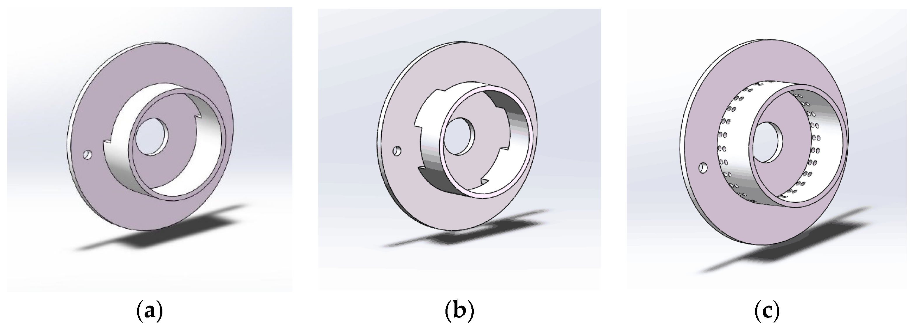
Figure 4.
Physical model of idealized MT airway.
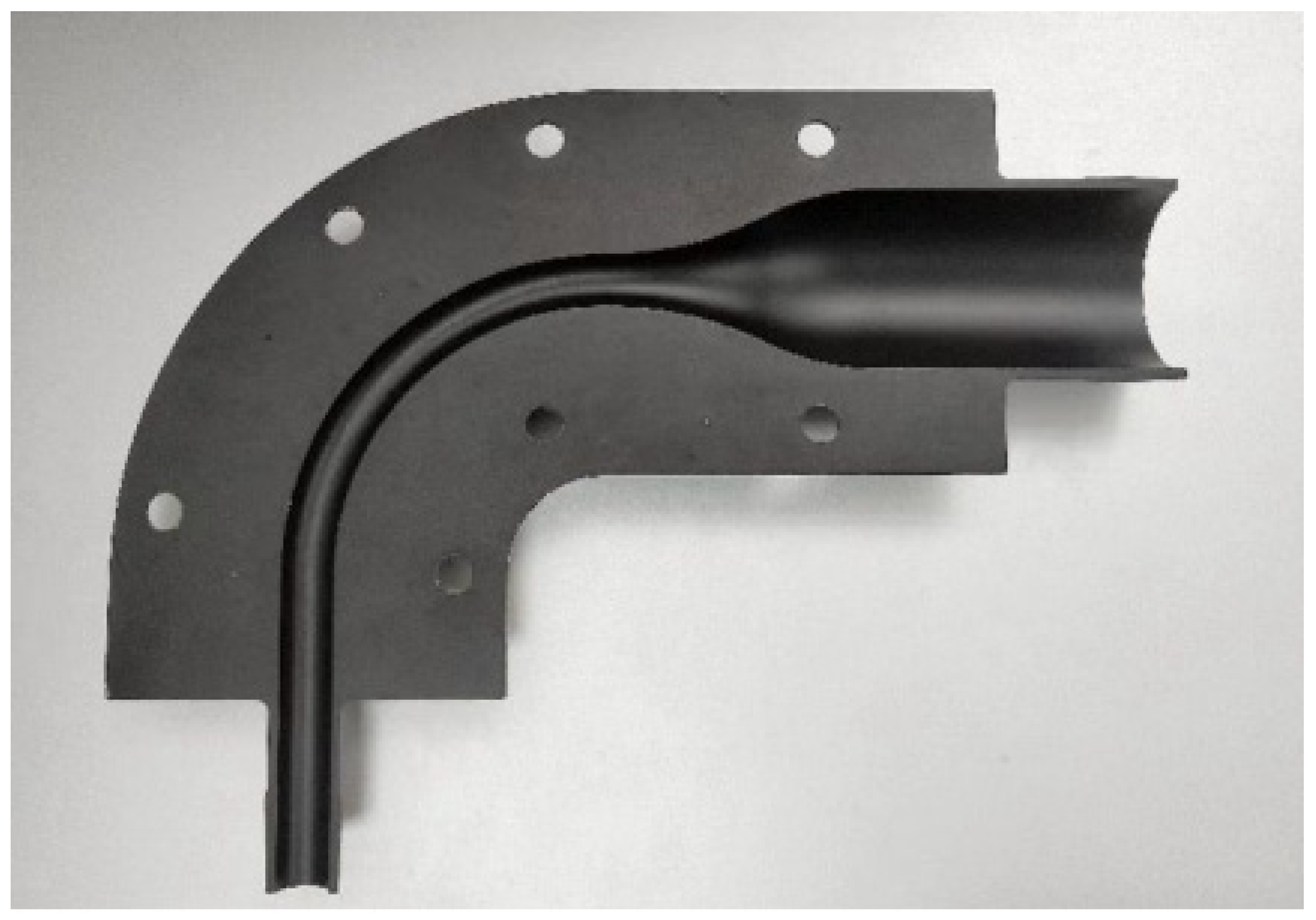
Figure 5.
Geometric structures of the VMNs with different air inlets connected to the idealized MT model: (a) semi-circular inlet; (b) symmetrical four-inlet; (c) multiple-orifice inlet.
Figure 5.
Geometric structures of the VMNs with different air inlets connected to the idealized MT model: (a) semi-circular inlet; (b) symmetrical four-inlet; (c) multiple-orifice inlet.
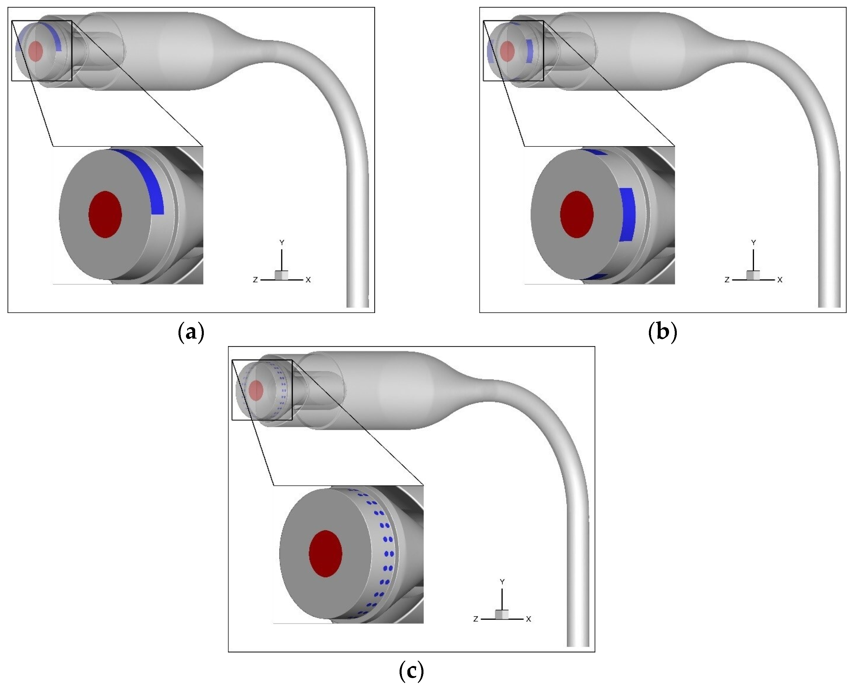
Figure 6.
Mesh of MT model with semi-circular inlet and velocity monitoring line.
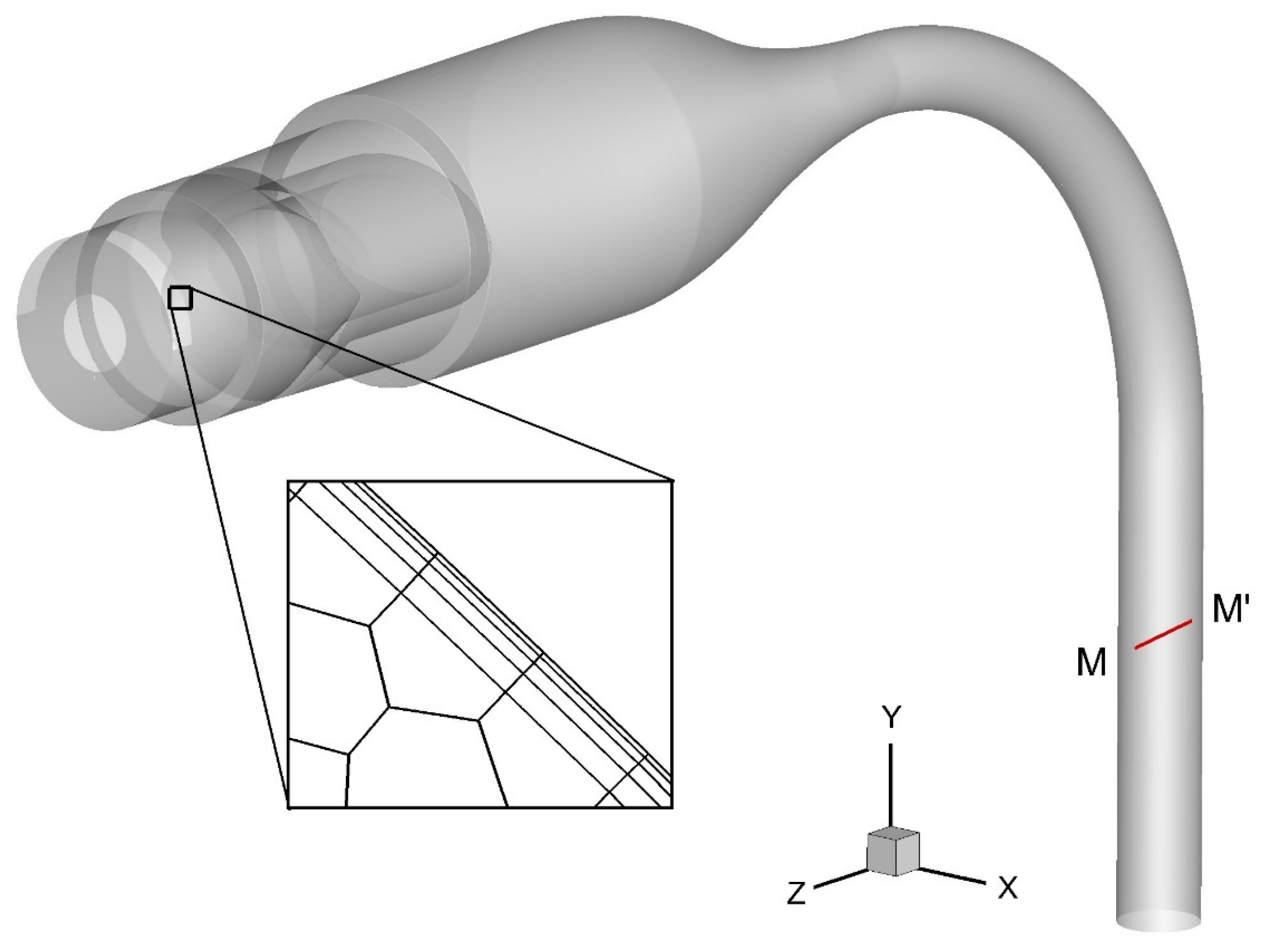
Figure 7.
Mesh independence test for the semi-circular inlet model.

Figure 8.
Airflow velocity distributions within models with different inlet structures: (a) on the mid-plane of VMN1; (b) on multiple cross-sections of VMN2; (c) on the mid-plane of VMN1; (d) on multiple cross-sections of VMN2; (e) on the mid-plane of VMN3; (f) on multiple cross-sections of VMN3.
Figure 8.
Airflow velocity distributions within models with different inlet structures: (a) on the mid-plane of VMN1; (b) on multiple cross-sections of VMN2; (c) on the mid-plane of VMN1; (d) on multiple cross-sections of VMN2; (e) on the mid-plane of VMN3; (f) on multiple cross-sections of VMN3.

Figure 9.
Deposition fraction (DF) of nebulized droplets in the idealized MT airway using different handheld nebulizer inlet structures and Yuwell HL100A VMN [31]. Each point represents the mean of three replicate experiments. Error bars represent standard deviations.
Figure 9.
Deposition fraction (DF) of nebulized droplets in the idealized MT airway using different handheld nebulizer inlet structures and Yuwell HL100A VMN [31]. Each point represents the mean of three replicate experiments. Error bars represent standard deviations.
Disclaimer/Publisher’s Note: The statements, opinions and data contained in all publications are solely those of the individual author(s) and contributor(s) and not of MDPI and/or the editor(s). MDPI and/or the editor(s) disclaim responsibility for any injury to people or property resulting from any ideas, methods, instructions or products referred to in the content. |
© 2023 by the authors. Licensee MDPI, Basel, Switzerland. This article is an open access article distributed under the terms and conditions of the Creative Commons Attribution (CC BY) license (https://creativecommons.org/licenses/by/4.0/).
Share and Cite
MDPI and ACS Style
Liu, Y.; Chen, X.; Li, Z.; Yang, H.; Wang, J. Optimization of Vibrating Mesh Nebulizer Air Inlet Structure for Pulmonary Drug Delivery. Atmosphere 2023, 14, 1509. https://doi.org/10.3390/atmos14101509
AMA Style
Liu Y, Chen X, Li Z, Yang H, Wang J. Optimization of Vibrating Mesh Nebulizer Air Inlet Structure for Pulmonary Drug Delivery. Atmosphere. 2023; 14(10):1509. https://doi.org/10.3390/atmos14101509
Chicago/Turabian StyleLiu, Yu, Xiaole Chen, Zhengqi Li, Huizhen Yang, and Jianwei Wang. 2023. "Optimization of Vibrating Mesh Nebulizer Air Inlet Structure for Pulmonary Drug Delivery" Atmosphere 14, no. 10: 1509. https://doi.org/10.3390/atmos14101509
Note that from the first issue of 2016, this journal uses article numbers instead of page numbers. See further details here.