

Particulate Matter Emission and Air Pollution Reduction by Applying Variable Systems in Tribologically Optimized Diesel Engines for Vehicles in Road Traffic

 , , ,
, , ,  and
and 
Abstract
:1. Introduction
2. Emission Regulations and the Proper Research Area
2.1. EU Emission Regulations for Heavy-Duty Bus and Truck Engines
2.2. Periodic Technical Inspection of Vehicles That Are Used on Public Roads
2.3. Occupational Health and Low-Emission Zones in the EU
2.4. Contribution to Research in the Area of Reducing PM Emissions from Diesel Engines in City Traffic
3. Materials and Methods
3.1. Single-Cylinder Experimental Engine Tests
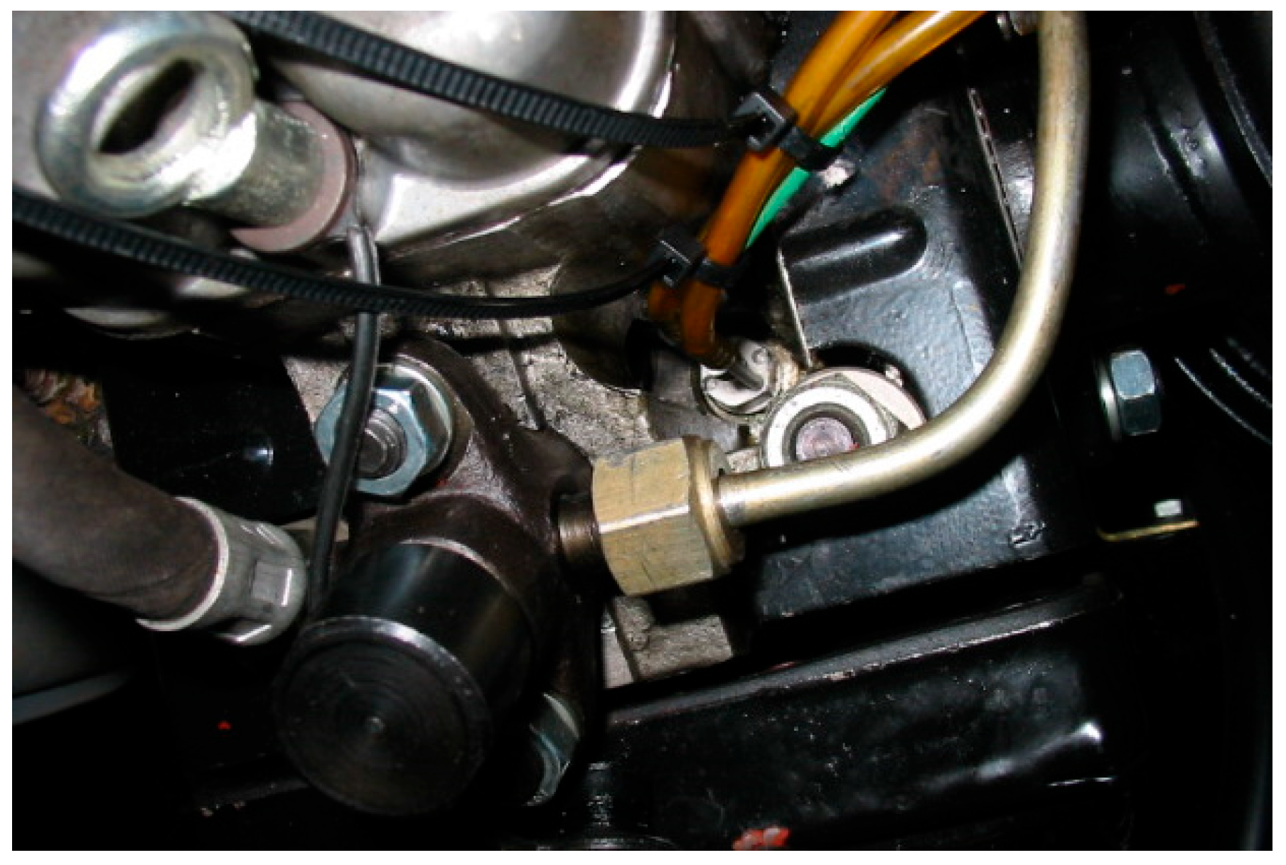
3.1.1. Test Bench with Measuring and Data Acquisition System Description
3.1.2. Operating Points and PM Emission Calculation
3.2. Tribological Tests of the Aluminum Cylinder Sliding Surface with Steel Reinforcement
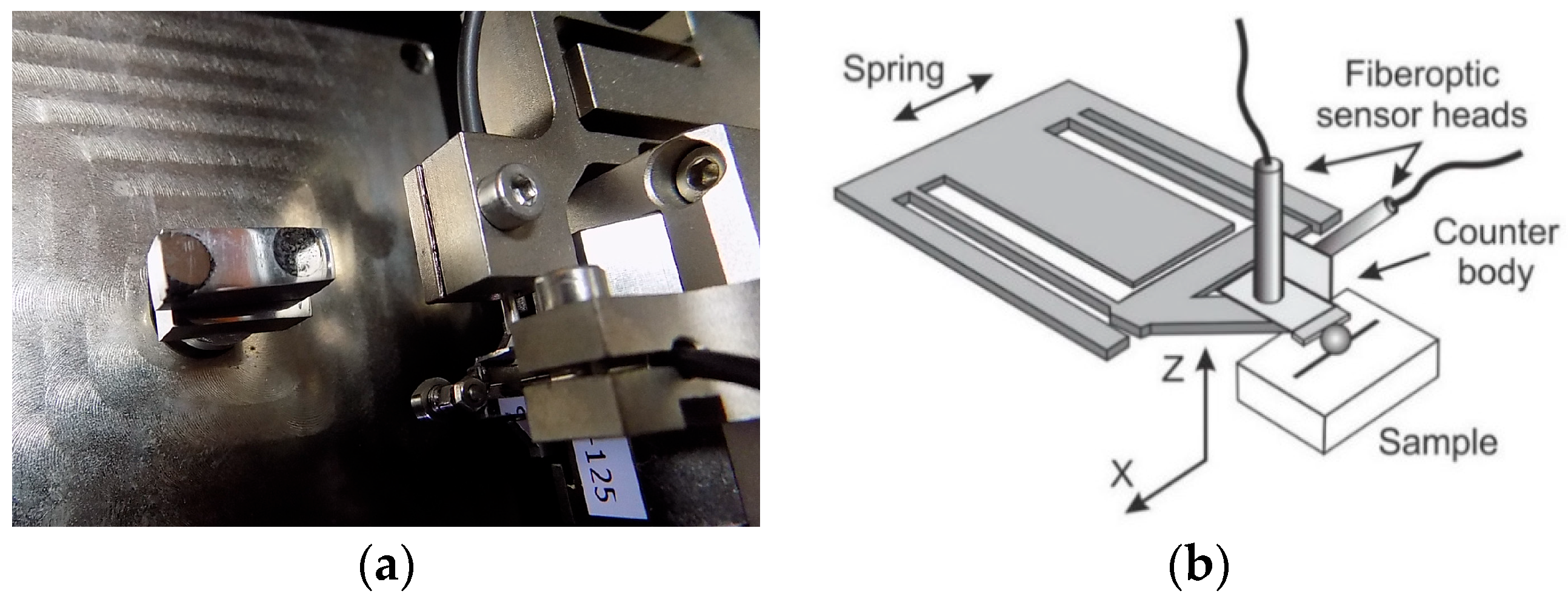
3.2.1. Applied Materials and Tribometer: Tests under Sliding Conditions
3.2.2. Applied Load and Speed Parameters during Tribological Tests
- Ww—degre of wear (mm3∙m−1);
- Vw—volume of worn cylinder material (mm3);
- Sw—sliding distance (m).
4. Results
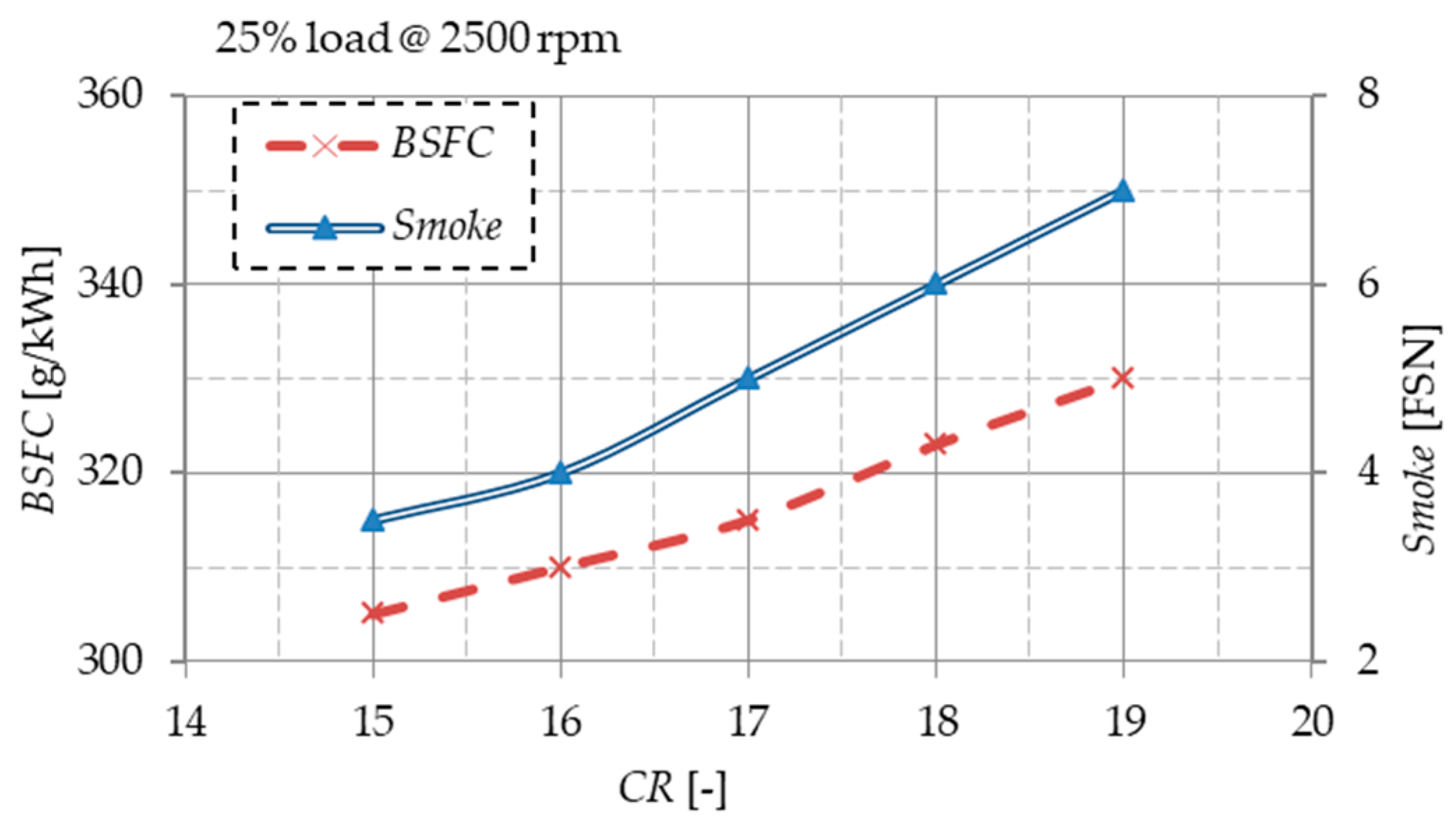
4.1. Particulate Matter Emissions from the Diesel Engine on the Test Bench
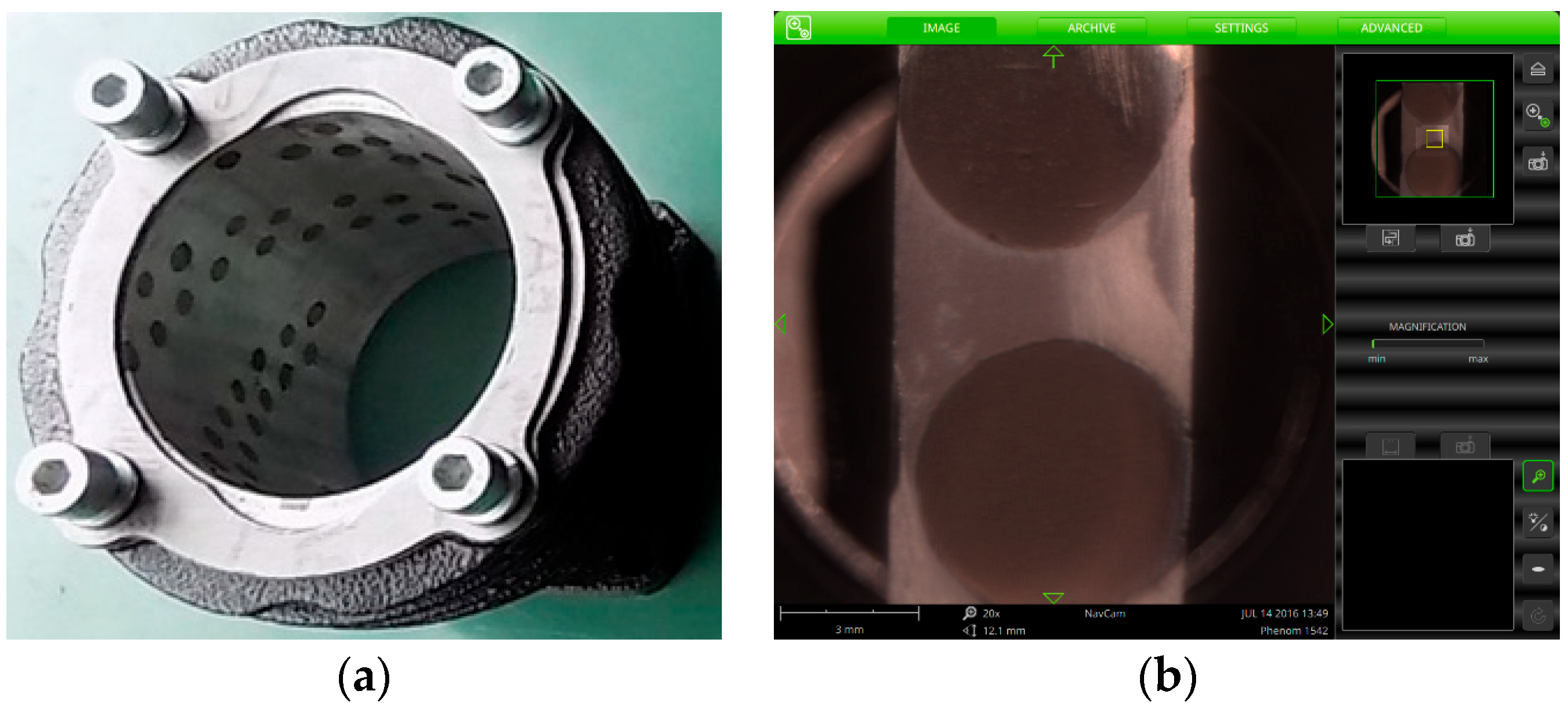
4.2. Results of a Tribological Investigation of a Cylinder Liner Sample with Reinforcements
Friction Coefficient and Penetration Depth of a Worn Sample of the Aluminum Cylinder with Reinforcements at Maximum Load and Sliding Speed
5. Discussion
- Changes in Tmax and Pmax under a higher engine speed of 2325 rpm and a full load of 0.55 MPa depending on CR values for SOI = 14 cad BTDC and SOI = 18.5 cad BTDC;
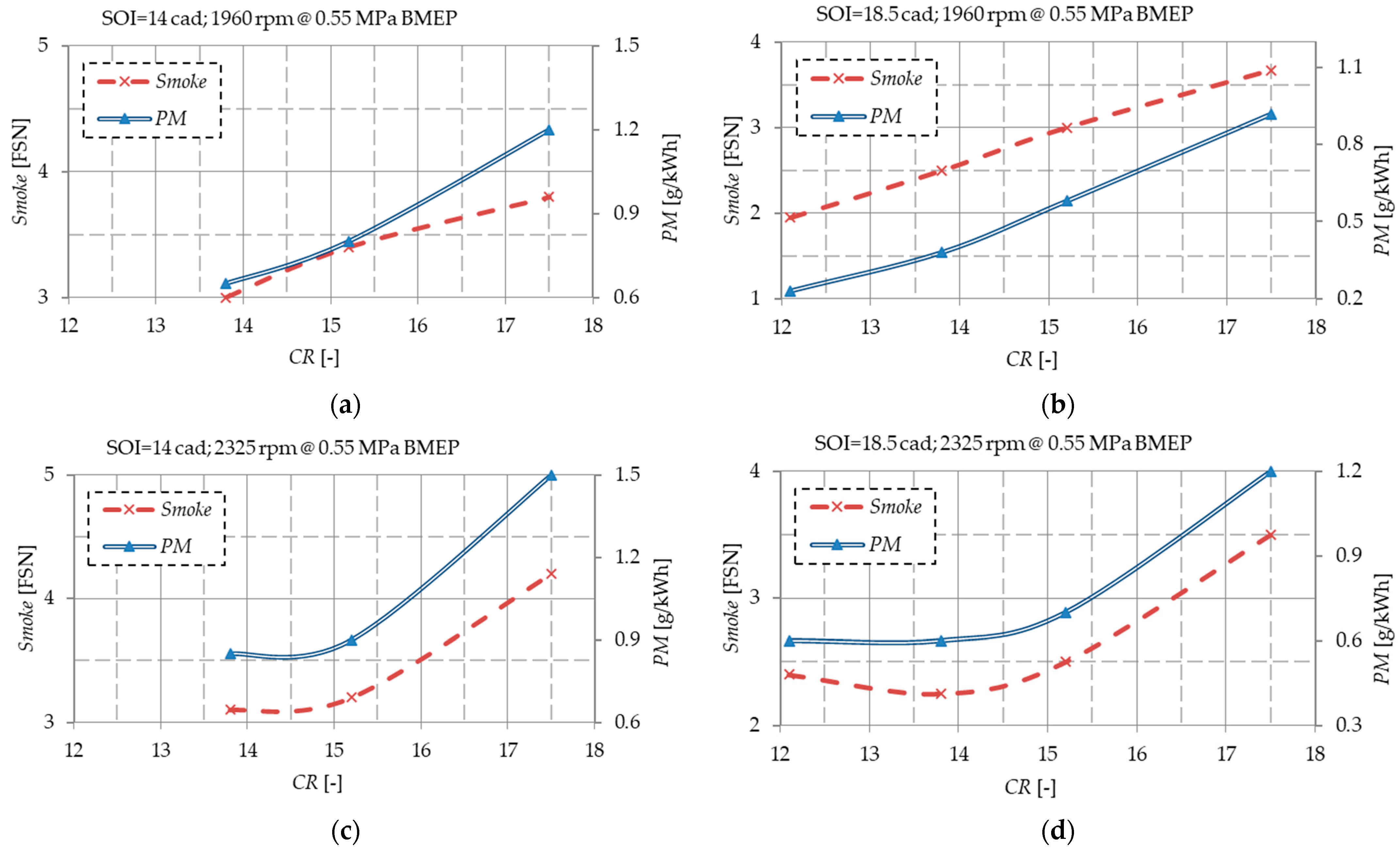
- Changes in smoke and PM emissions under a full load of 0.55 MPa and a middle engine speed of 1960 rpm depending on CR values for SOI = 14 cad BTDC and SOI = 18.5 cad BTDC and under a higher engine speed of 2325 rpm for SOI = 14 cad BTDC and SOI = 18.5 cad BTDC;
- Influence of CR and load under a higher engine speed of 2325 rpm and optimal SOI on PM emission and relations between PM emission and BSFC vs. NOx emission for optimal SOI and CR values under a higher engine speed of 2325 rpm;
- Relations between PM and NOx emissions depending on the CR value according to ESC emission cycle conditions under SOI = 14 cad BTDC and SOI = 18.5 cad BTDC.
- Friction coefficient and penetration depth change depending on the sliding time, distance, and cycles at constant maximum load and sliding speed, 0.9 N and 0.015 m/s, for the base material and for the reinforcement;
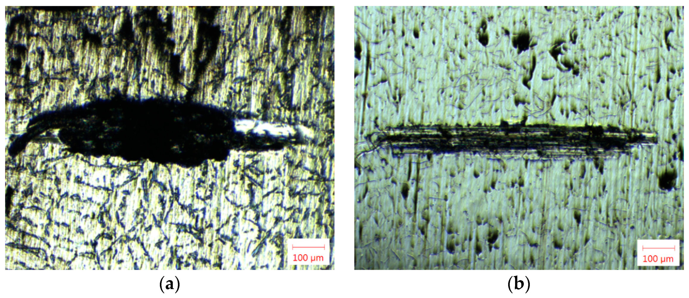
- Optical micrographs of damaged material surfaces after the sliding test at constant load of 0.9 N and speed of 0.015 m/s conditions for the base material and the reinforcement;
- Optical micrographs of the tribometer counter body ball surface after testing the material at a constant load of 0.9 N and speed of 0.015 m/s for the cylinder base and for reinforcement.
6. Conclusions
- (i)
- Due to their good fuel economy, diesel engines have potential as power units for hybrid vehicles. At the same time, it is necessary to reduce the emissions of NOx and PM, i.e., the smoke from diesel engines, due to their extremely negative impact on human health and the pollution of the environment with harmful exhaust gases;
- (ii)
- The emission of exhaust gases from diesel engines is increasingly limited over time by strict emission regulations. Therefore, modern technologies were developed and applied over time, such as direct fuel injection under high pressure, supercharging, exhaust gas recirculation, a variable valve train, homogenous charge compression ignition, lowering engine displacement, catalytic treatment of raw combustion products, particle filters, etc.;
- (iii)
- This paper proposes the application of an automatically variable compression ratio. The research results can be used when constructing such IC engines, which should contribute to lower emissions and fuel consumption;
- (iv)
- At a maximum engine speed of 2325 rpm and a full load of 0.55 MPa, a decrease in Tmax and Pmax in the cylinder can be observed with a decrease in the values of CR and SOI;
- (v)
- The consequence of the reduction in Tmax in the cylinder when reducing the CR and SOI values at the maximum experimental engine speed and full load is the increased emission of PM and smoke, which, on the other hand, contributes to the reduction in NOx emissions. A similar dependence was recorded at an average engine speed of 1960 rpm and a full load of 0.55 MPa;
- (vi)
- At the maximum engine speed of 2325 rpm under the optimum SOI value, the minimum PM emission was achieved at low engine loads;
- (vii)
- With later SOI timing, it is possible to achieve engine operation at the smoke limit with minimal BSFC and NOx emissions;
- (viii)
- The combustion of engine oil that blows into the cylinder due to the wear of the cylinder liner sliding surface is one of the important sources of PM and smoke emissions inside IC engines.
- (ix)
- At the maximum load of 0.9 N and maximum sliding speed of 0.015 m/s according to the experimental conditions, the mean value of the friction coefficient of the reinforcement 0.176 is lower compared to the comparative value for the cylinder base material 0.202;
- (x)
- At maximum load and sliding speed, the material of the reinforcement wears evenly and less intensively, so the wear curve does not have pronounced oscillations, which is not the case with the material of the cylinder base, which is made of a softer aluminum alloy;
- (xi)
- Analyzing the optical micrographs of the worn cylinder surface material sample, it was observed that during the investigation of the base material, there was a recorded sticking of the material, which intensified the process of adhesive wear. This is not the case with the reinforcement material, which is harder and whose surface shows traces of abrasive wear, and no material transfer, i.e., adhesive wear, was recorded;
- (xii)
- The tribological optimization of the cylinder indicates the further verification of the construction with reinforcements from the aspect of reducing mechanical losses, i.e., fuel consumption and emissions.
Author Contributions
Funding
Informed Consent Statement
Data Availability Statement
Acknowledgments
Conflicts of Interest
References
- Ravi, S.S.; Osipov, S.; Turner, J.W.G. Impact of Modern Vehicular Technologies and Emission Regulations on Improving Global Air Quality. Atmosphere 2023, 14, 1164. [Google Scholar] [CrossRef]
- Vouitsis, I.; Portugal, J.; Kontses, A.; Karlsson, H.L.; Faria, M.; Elihn, K.; Juárez-Facio, A.T.; Amato, F.; Piña, B.; Samaras, Z. Transport-related airborne nanoparticles: Sources, different aerosol modes, and their toxicity. Atmos. Environ. 2023, 301, 119698. [Google Scholar] [CrossRef]
- Hao, Y.; Gao, C.; Deng, S.; Yuan, M.; Song, W.; Lu, Z.; Qiu, Z. Chemical characterization of PM2.5 emitted from motor vehicles powered by diesel, gasoline, natural gas and methanol fuel. Sci. Total Environ. 2019, 674, 128–139. [Google Scholar] [CrossRef]
- Liu, Y.; Zhang, W.; Yang, W.; Bai, Z.; Zhao, X. Chemical Compositions of PM2.5 Emitted from Diesel Trucks and Construction Equipment. Aerosol. Sci. Eng. 2018, 2, 51–60. [Google Scholar] [CrossRef]
- Xing, Y.; Xu, Y.; Shi, M.; Lian, Y. The impact of PM2.5 on the human respiratory system. J. Thorac. Dis. 2016, 8, E69–E74. [Google Scholar] [CrossRef] [PubMed]
- Garcia, A.; Santa-Helena, E.; De Falco, A.; De Paula Ribeiro, J.; Gioda, A.; Gioda, C.R. Toxicological Effects of Fine Particulate Matter (PM2.5): Health Risks and Associated Systemic Injuries—Systematic Review. Water Air Soil Pollut. 2023, 234, 346. [Google Scholar] [CrossRef] [PubMed]
- Gürbüz, H.; Şöhret, Y.; Ekici, S. Evaluating effects of the COVID-19 pandemic period on energy consumption and enviro-economic indicators of Turkish road transportation. Energy Sources Part A Recovery Util. Environ. Eff. 2021. [Google Scholar] [CrossRef]
- Reitz, R.D.; Ogawa, H.; Payri, R.; Fansler, T.; Kokjohn, S.; Moriyoshi, Y.; Agarwal, A.K.; Arcoumanis, D.; Assanis, D.; Bae, C.; et al. IJER editorial: The future of the internal combustion engine. Int. J. Engine Res. 2020, 21, 3–10. [Google Scholar] [CrossRef]
- Mustafi, N.N. An Overview of Hybrid Electric Vehicle Technology. In Engines and Fuels for Future Transport. Energy, Environment, and Sustainability; Kalghatgi, G., Agarwal, A.K., Leach, F., Senecal, K., Eds.; Springer: Singapore, 2022; pp. 73–102. [Google Scholar] [CrossRef]
- Correa, G.; Muñoz, P.M.; Rodriguez, C.R. A comparative energy and environmental analysis of a diesel, hybrid, hydrogen and electric urban bus. Energy 2019, 187, 115906. [Google Scholar] [CrossRef]
- Skrúcaný, T.; Kendra, M.; Stopka, O.; Milojević, S.; Figlus, T.; Csiszár, C. Impact of the Electric Mobility Implementation on the Greenhouse Gases Production in Central European Countries. Sustainability 2019, 11, 4948. [Google Scholar] [CrossRef]
- Eichinger, T.; Silberhorn, G.; Hofmann, S. MAN Smart Hybrid Experience. In Heavy-Duty-, On-und Off-Highway-Motoren 2021; Liebl, J., Ed.; Springer: Wiesbaden, Germany, 2022; pp. 202–218. [Google Scholar] [CrossRef]
- Fiebig, M.; Wiartalla, A.; Holderbaum, B.; Kiesow, S. Particulate emissions from diesel engines: Correlation between engine technology and emissions. J. Occup. Med. Toxicol. 2014, 9, 6. [Google Scholar] [CrossRef] [PubMed]
- Balaji, R.; Yeditha, V.S.; Premkumar, B.C.; Talari, S.; Madaka, R.M.R.; Edara, G. Controlling NOx in modified high pressure split injection single cylinder diesel engine with EGR-A mathematical approach. Int. J. Heat. Technol. 2023, 41, 679–686. [Google Scholar] [CrossRef]
- Zhai, C.; Chang, F.; Jin, Y.; Luo, H. Investigations on the Diesel Spray Characteristic and Tip Penetration Model of Multi-Hole Injector with Micro-Hole under Ultra-High Injection Pressure. Sustainability 2023, 15, 11114. [Google Scholar] [CrossRef]
- Zhang, Z.; Liu, H.; Yue, Z.; Wu, Y.; Kong, X.; Zheng, Z.; Yao, M. Effects of Multiple Injection Strategies on Heavy-Duty Diesel Energy Distributions and Emissions under High Peak Combustion Pressures. Front. Energy Res. 2022, 10, 857077. [Google Scholar] [CrossRef]
- Agarwal, A.; Solanki, V.; Krishnamoorthi, M. Experimental Evaluation of Pilot and Main Injection Strategies on Gasoline Compression Ignition Engine—Part 2: Performance and Emissions Characteristics. SAE Int. J. Engines 2023, 16, 833–852. [Google Scholar] [CrossRef]
- Chen, Y.; Li, X.; Shi, S.; Zhao, Q.; Liu, D.; Chang, J.; Liu, F. Effects of intake swirl on the fuel/air mixing and combustion performance in a lateral swirl combustion system for direct injection diesel engines. Fuel 2021, 286, 119376. [Google Scholar] [CrossRef]
- Sarangi, A.K.; McTaggart-Cowan, G.P.; Garner, C.P. The Impact of Fuel Injection Timing and Charge Dilution Rate on Low Temperature Combustion in a Compression Ignition Engine. Energies 2023, 16, 139. [Google Scholar] [CrossRef]
- Akolaş, H.İ.; Kaleli, A.; Bakirci, K. Design and implementation of an autonomous EGR cooling system using deep neural network prediction to reduce NOx emission and fuel consumption of diesel engine. Neural Comput. Appl. 2021, 33, 1655–1670. [Google Scholar] [CrossRef]
- Milojević, S.; Savić, S.; Marić, D.; Stopka, O.; Krstić, B.; Stojanović, B. Correlation between Emission and Combustion Characteristics with the Compression Ratio and Fuel Injection Timing in Tribologically Optimized Diesel Engine. Teh. Vjesn. 2022, 29, 1210–1219. [Google Scholar] [CrossRef]
- Martins, J.; Brito, F.P. Alternative Fuels for Internal Combustion Engines. Energies 2020, 13, 4086. [Google Scholar] [CrossRef]
- Kashyap, D.; Das, S.; Kalita, P. Influence of Oxygenated Fuel and Additives in Biofuel Run Compression Ignition Engine. In Potential and Challenges of Low Carbon Fuels for Sustainable Transport. Energy, Environment, and Sustainability; Agarwal, A.K., Valera, H., Eds.; Springer: Singapore, 2022; pp. 183–243. [Google Scholar] [CrossRef]
- Gürbüz, H.; Demirtürk, S.; Akçay, İ.H.; Akçay, H. Effect of port injection of ethanol on engine performance, exhaust emissions and environmental factors in a dual-fuel diesel engine. Energy Environ. 2020, 32, 784–802. [Google Scholar] [CrossRef]
- Milojević, S. Sustainable application of natural gas as engine fuel in city buses: Benefit and restrictions. J. Appl. Eng. Sci. 2017, 15, 81–88. [Google Scholar] [CrossRef]
- Yuan, X.; Liu, H.; Gao, Y. Diesel Engine SCR Control: Current Development and Future Challenges. Emiss. Control Sci. Technol. 2015, 1, 121–133. [Google Scholar] [CrossRef]
- Zannis, T.C.; Katsanis, J.S.; Christopoulos, G.P.; Yfantis, E.A.; Papagiannakis, R.G.; Pariotis, E.G.; Rakopoulos, D.C.; Rakopoulos, C.D.; Vallis, A.G. Marine Exhaust Gas Treatment Systems for Compliance with the IMO 2020 Global Sulfur Cap and Tier III NOx Limits: A Review. Energies 2022, 15, 3638. [Google Scholar] [CrossRef]
- Choi, B.; Lee, K.; Son, G. Review of Recent After-Treatment Technologies for De-NOx Process in Diesel Engines. Int. J. Automot. Technol. 2020, 21, 1597–1618. [Google Scholar] [CrossRef]
- Shilov, V.; Potemkin, D.; Rogozhnikov, V.; Snytnikov, P. Recent Advances in Structured Catalytic Materials Development for Conversion of Liquid Hydrocarbons into Synthesis Gas for Fuel Cell Power Generators. Materials 2023, 16, 599. [Google Scholar] [CrossRef] [PubMed]
- Lott, P.; Deutschmann, O. Lean-Burn Natural Gas Engines: Challenges and Concepts for an Efficient Exhaust Gas Aftertreatment System. Emiss. Control Sci. Technol. 2021, 7, 1–6. [Google Scholar] [CrossRef]
- Cesur, I.; Akgündüz, M.; Çelik, H.A.; Çay, Y.; Ergen, G. Tribological Analysis and Optimization of Ring-Cylinder Couple Coated with Different Materials. Arab. J. Sci. Eng. 2023, 1–12. [Google Scholar] [CrossRef]
- Mishra, P.C.; Roychoudhury, A.; Banerjee, A.; Saha, N.; Das, S.R.; Das, A. Coated Piston Ring Pack and Cylinder Liner Elastodynamics in Correlation to Piston Subsystem Elastohydrodynamic: Through FEA Modelling. Lubricants 2023, 11, 192. [Google Scholar] [CrossRef]
- Dolata, A.J.; Wieczorek, J.; Dyzia, M.; Starczewski, M. Assessment of the Tribological Properties of Aluminum Matrix Composites Intended for Cooperation with Piston Rings in Combustion Engines. Materials 2022, 15, 3806. [Google Scholar] [CrossRef]
- Li, C.; Chen, X.; Liu, H.; Dong, L.; Jian, H.; Wang, J.; Du, F. Tribological Performance and Scuffing Resistance of Cast-Iron Cylinder Liners and Al-Si Alloy Cylinder Liners. Coatings 2023, 13, 1951. [Google Scholar] [CrossRef]
- Alshwawra, A.; Abo Swerih, A.; Sakhrieh, A.; Dinkelacker, F. Structural Performance of Additively Manufactured Cylinder Liner—A Numerical Study. Energies 2022, 15, 8926. [Google Scholar] [CrossRef]
- Stojanović, B.Ž.; Milojević, S.T. Characterization, manufacturing and application of metal matrix composites. In Advances in Materials Science Research; Wythers, M.C., Ed.; Nova Science Publishers: New York, NY, USA, 2017; Volume 30, pp. 83–113. [Google Scholar]
- Pawlus, P.; Koszela, W.; Reizer, R. Surface Texturing of Cylinder Liners: A Review. Materials 2022, 15, 8629. [Google Scholar] [CrossRef]
- Sandra, V.; Stojanović, B.; Ivanović, L.; Miladinović, S.; Milojević, S. Application of nanocomposites in the automotive industry. Mobil. Veh. Mech. MVM 2019, 45, 51–64. [Google Scholar] [CrossRef]
- Milojević, S.; Džunić, D.; Marić, D.; Skrúcaný, T.; Mitrović, S.; Pešić, R. Tribological Assessment of Aluminum Cylinder Material for Piston Compressors in Trucks and Buses Brake Systems. Teh. Vjesn. 2021, 28, 1268–1276. [Google Scholar] [CrossRef]
- Milojević, S.; Savić, S.; Mitrović, S.; Marić, D.; Krstić, B.; Stojanović, B.; Popović, V. Solving the Problem of Friction and Wear in Auxiliary Devices of Internal Combustion Engines on the Example of Reciprocating Air Compressor for Vehicles. Teh. Vjesn. 2023, 30, 122–130. [Google Scholar] [CrossRef]
- Holmberg, K.; Andersson, P.; Erdemir, A. Global energy consumption due to friction in passenger cars. Tribol. Int. 2012, 47, 221–234. [Google Scholar] [CrossRef]
- Holmberg, K.; Andersson, P.; Nylund, N.O.; Mäkelä, K.; Erdemir, A. Global energy consumption due to friction in trucks and buses. Tribol. Int. 2014, 78, 94–114. [Google Scholar] [CrossRef]
- Li, Y.; Huang, S.; Liu, Y.; Ju, Y. Recycling Potential of Plastic Resources from End-of-Life Passenger Vehicles in China. Int. J. Environ. Res. Public Health 2021, 18, 10285. [Google Scholar] [CrossRef] [PubMed]
- Skrúcaný, T.; Semanová, S.; Milojević, S.; Asonja, A. New Technologies Improving Aerodynamic Properties of Freight Vehicles. Appl. Eng. Lett. J. Eng. Appl. Sci. 2019, 4, 48–54. [Google Scholar] [CrossRef]
- Elwert, T.; Goldmann, D.; Römer, F.; Buchert, M.; Merz, C.; Schueler, D.; Sutter, J. Current Developments and Challenges in the Recycling of Key Components of (Hybrid) Electric Vehicles. Recycling 2016, 1, 25–60. [Google Scholar] [CrossRef]
- Almeida Streitwieser, D.; Arteaga, A.; Gallo-Cordova, A.; Hidrobo, A.; Ponce, S. Chemical Recycling of Used Motor Oil by Catalytic Cracking with Metal-Doped Aluminum Silicate Catalysts. Sustainability 2023, 15, 10522. [Google Scholar] [CrossRef]
- Milojević, S.; Pešić, R.; Lukić, J.; Taranović, D.; Skrucany, T.; Stojanović, B. Vehicles optimization regarding to requirements of recycling Example: Bus dashboard. In Proceedings of the IOP Conference Series: Materials Science and Engineering, Kragujevac, Serbia, 5–7 September 2019. [Google Scholar] [CrossRef]
- Milojević, S.; Miletić, I.; Stojanović, B.; Milojević, I.; Miletić, M. Logistics of electric drive motor vehicles recycling. Mobil. Veh. Mech. MVM 2020, 46, 33–43. [Google Scholar] [CrossRef]
- EU: Heavy-Duty Truck and Bus Engines. Available online: https://dieselnet.com/standards/eu/hd.php (accessed on 8 November 2023).
- Bielaczyc, P.; Woodburn, J. Trends in Automotive Emission Legislation: Impact on LD Engine Development, Fuels, Lubricants and Test Methods: A Global View, with a Focus on WLTP and RDE Regulations. Emiss. Control Sci. Technol. 2019, 5, 86–98. [Google Scholar] [CrossRef]
- Tapak, P.; Kocur, M.; Rabek, M.; Matej, J. Periodical Vehicle Inspections with Smart Technology. Appl. Sci. 2023, 13, 7241. [Google Scholar] [CrossRef]
- Botero, M.L.; Londoño, J.; Agudelo, A.F.; Agudelo, J.R. Particle Number Emission for Periodic Technical Inspection in a Bus Rapid Transit System. Emiss. Control Sci. Technol. 2023, 9, 128–139. [Google Scholar] [CrossRef]
- Melas, A.; Selleri, T.; Suarez-Bertoa, R.; Giechaskiel, B. Evaluation of Solid Particle Number Sensors for Periodic Technical Inspection of Passenger Cars. Sensors 2021, 21, 8325. [Google Scholar] [CrossRef]
- Dziedziak, P.; Szczepański, T.; Niewczas, A.; Ślęzak, M. Car reliability analysis based on periodic technical tests. Open Eng. 2021, 11, 630–638. [Google Scholar] [CrossRef]
- Giechaskiel, B.; Lahde, T.; Suarez-Bertoa, R.; Clairotte, M.; Grigoratos, T.; Zardini, A.; Perujo, A.; Martini, G. Particle number measurements in the European legislation and future JRC activities. Combust. Engines 2018, 174, 3–16. [Google Scholar] [CrossRef]
- Shin, J.; Kim, B.; Kim, H.-R. Characteristics of Occupational Exposure to Diesel Engine Exhaust for Shipyard Transporter Signal Workers. Int. J. Environ. Res. Public Health 2020, 17, 4398. [Google Scholar] [CrossRef]
- Biró, N.; Kiss, P. Euro VI-d Compliant Diesel Engine’s Sub-23 nm Particle Emission. Sensors 2023, 23, 590. [Google Scholar] [CrossRef]
- Krais, A.M.; Essig, J.Y.; Gren, L.; Vogs, C.; Assarsson, E.; Dierschke, K.; Nielsen, J.; Strandberg, B.; Pagels, J.; Broberg, K.; et al. Biomarkers after Controlled Inhalation Exposure to Exhaust from Hydrogenated Vegetable Oil (HVO). Int. J. Environ. Res. Public Health 2021, 18, 6492. [Google Scholar] [CrossRef]
- Landwehr, K.R.; Larcombe, A.N.; Reid, A.; Mullins, B.J. Critical Review of Diesel Exhaust Exposure Health Impact Research Relevant to Occupational Settings: Are We Controlling the Wrong Pollutants? Exp. Health 2021, 13, 141–171. [Google Scholar] [CrossRef]
- EU: Urban Vehicle Access Regulations. Available online: https://transport.ec.europa.eu/transport-themes/urban-transport/urban-vehicle-access-regulations_en (accessed on 9 November 2023).
- EU: Urban Access Regulations in Europe. Available online: https://urbanaccessregulations.eu/ (accessed on 8 December 2023).
- Milojević, S.; Pešić, R. Determination of Combustion Process Model Parameters in Diesel Engine with Variable Compression Ratio. J. Combust. 2018, 2018, 5292837. [Google Scholar] [CrossRef]
- Narayan, S.; Milojevic, S.; Gupta, V. Combustion Monitoring in Engines Using Accelerometer Signals. J. Vibroeng. 2019, 21, 1552–1563. [Google Scholar] [CrossRef]
- Milojević, S.; Dragojlović, D.; Gročić, D. CNG propulsion system for reducing noise of existing city buses. J. Appl. Eng. Sci. 2016, 14, 377–382. [Google Scholar] [CrossRef]
- Milojević, S.; Skrucany, T.; Milošević, H.; Stanojević, D.; Pantić, M.; Stojanović, B. Alternative Drive Systems and Environmentaly Friendly Public Passengers Transport. Appl. Eng. Lett. 2018, 3, 105–113. [Google Scholar] [CrossRef]
- Skrúcaný, T.; Milojević, S.; Semanová, Š.; Čechovič, T.; Figlus, T.; Synák, F. The Energy Efficiency of Electric Energy as a Traction Used in Transport. Transp. Tech. Technol. 2018, 14, 9–14. [Google Scholar] [CrossRef]
- Stark, M.; Härtl, M.; Jaensch, M.; Preuss, A.C.; Pryymak, K.; Matz, G.; Gohl, M. Clarification of Fuel and Oil Flow Behavior around the Piston Rings of Internal Combustion Engines—Simultaneous Analysis of Oil Flow Behavior and Oil Emissions during Transient Operation; SAE Technical Paper; No. 2023-32-0045; Society of Automotive Engineers of Japan: Tokyo, Japan, 2023. [Google Scholar] [CrossRef]
- Pardo-García, C.; Orjuela-Abril, S.; Pabón-León, J. Investigation of Emission Characteristics and Lubrication Oil Properties in a Dual Diesel–Hydrogen Internal Combustion Engine. Lubricants 2022, 10, 59. [Google Scholar] [CrossRef]
- Tomanik, E.; Christinelli, W.; Souza, R.M.; Oliveira, V.L.; Ferreira, F.; Zhmud, B. Review of Graphene-Based Materials for Tribological Engineering Applications. Eng 2023, 4, 2764–2811. [Google Scholar] [CrossRef]
- Milojević, S.; Stojanović, B. Determination of tribological properties of aluminum cylinder by application of Taguchi method and ANN-based model. J. Braz. Soc. Mech. Sci. Eng. 2018, 40, 571. [Google Scholar] [CrossRef]
- Samoilenko, D.; Cho, H.M. Improvement of combustion efficiency and emission characteristics of IC diesel engine operating on ESC cycle applying Variable Geometry Turbocharger (VGT) with vaneless turbine volute. Int. J. Automot. Technol. 2013, 14, 521–528. [Google Scholar] [CrossRef]
- Soto, F.; Marques, G.; Izquierdo, L.S.; Torres-Jiménez, E.; Quaglia, S.; Guerrero-Villar, F.; Dorado-Vicente, R.; Abdalla, J. Performance and regulated emissions of a medium-duty diesel engine fueled with biofuels from sugarcane over the European steady cycle (ESC). Fuel 2021, 292, 120326. [Google Scholar] [CrossRef]
- Milojević, S. Analyzing the Impact of Variable Compression Ratio on Combustion Process in Diesel Engines. Ph.D. Thesis, University of Kragujevac, Faculty of Mechanical Engineering, Kragujevac, Serbia, 2004. [Google Scholar]
- Taranović, D.; Ninković, D.; Davinić, A.; Pešić, R.; Glišović, J.; Milojević, S. Valve dynamics in reciprocating compressors for motor vehicles. Teh. Vjesn. 2017, 24, 313–319. [Google Scholar] [CrossRef]
- Xiao, S.; Nie, A.; Zhang, Z.; Liu, S.; Song, M.; Zhang, H. Fault Diagnosis of a Reciprocating Compressor Air Valve Based on Deep Learning. Appl. Sci. 2020, 10, 6596. [Google Scholar] [CrossRef]
- Ouyang, J.-H.; Li, Y.-F.; Zhang, Y.-Z.; Wang, Y.-M.; Wang, Y.-J. High-Temperature Solid Lubricants and Self-Lubricating Composites: A Critical Review. Lubricants 2022, 10, 177. [Google Scholar] [CrossRef]
- Zhang, J.; Wang, Y.; Li, X.; Jiang, Z.; Xie, Y.; Zhu, Q. A Simulation Study on the Transient Motion of a Reciprocating Compressor Suction Valve Under Complicated Conditions. J. Fail. Anal. Prev. 2016, 16, 790–802. [Google Scholar] [CrossRef]
- Du, C.; Sheng, C.; Liang, X.; Rao, X.; Guo, Z. Effects of Temperature on the Tribological Properties of Cylinder-Liner Piston Ring Lubricated with Different Oils. Lubricants 2023, 11, 115. [Google Scholar] [CrossRef]
- Sun, J.; Li, J.; Liu, Y.; Huang, Z.; Cai, J. A Novel Oil-free Dual Piston Compressor Driven by a Moving Coil Linear Motor with Capacity Regulation Using R134a. Sustainability 2021, 13, 5029. [Google Scholar] [CrossRef]
- Sobotowski, R.; Porter, B.; Pilley, A. The Development of a Novel Variable Compression Ratio, Direct Injection Diesel Engine. SAE Trans. 1991, 100, 776–792. [Google Scholar]


| Stage/(Date) | Emission Test Cycle | CO | NMHC | CH4 a | NOx | PM | PN |
|---|---|---|---|---|---|---|---|
| [gkW−1h−1] | [kW−1h−1] | ||||||
| Euro V/(2008.10) | European Transient Cycle (ETC) | 4.0 | 0.55 | 1.1 | 2.0 | 0.03 | |
| Euro VI/(2013.01) | World Harmonized Transient Cycle (WHTC) | 4.0 | 0.16 b | 0.5 | 0.46 | 0.01 | 6.0 × 10¹¹ |
| Country | Effective Date Comments | PN TLV (cm−3) | Applicability |
|---|---|---|---|
| Netherlands | 2023.01 Regulation IENW/BSK-2021/125046 | 1,000,000 | All diesel LD vehicles with wall-flow filters (Euro 3-6) and HD vehicles: Euro VI |
| Belgium | 2022.07 Agreement of the Flemish, Walloon, and Brussels regions, announced in 2021.04 | 1,000,000 | Diesel LD vehicles: Euro 5B-6 |
| Germany | 2023.01 AU-Richtlinie, Verkehrsblatt nr. 8 of 2021.04. PN counter specification PTB-A 12.16 | 250,000 | Diesel vehicles: LD Euro 6 and HD Euro VI |
| Switzerland | 2023.01 Amendments to SR 741.437, announced in 2022.02 | 250,000 a | All diesel vehicles with wall-flow filters |
| Country of Region | LEZ Scope |
|---|---|
| Belgium | All vehicles with four or more wheels (planned); retrofit options 1 |
| Denmark | All diesel-powered vehicles above 3500 kg; stickers required; retrofit options 1 |
| Germany | All vehicles with four wheels; stickers required; retrofit options 1 |
| Greece | All vehicles; vehicles over or under 2200 kg |
| Italy | All vehicles, including mopeds and motorcycles |
| Italy/France, Mont Blanc tunnel | Lorries only; control at tunnel entry |
| Netherlands | Lorries over 3500 kg-camera-enforced |
| Sweden | All heavy, diesel-powered trucks and buses; stickers required |
| UK, London | Vans and similar vehicles over 1205 kg unladen and vehicles over 3500 kg-camera-enforced; foreign vehicles need to register |
| UK outside London | Public service buses only; retrofit options 1 |
| Czech Republic | Lorries over 3500 kg or 6000 kg; stickers required |
| Austrian LEZs | Lorries over 3500 kg; stickers required; some retrofit options 1 |
| Description | Values/Characteristics |
|---|---|
| Manufacturer/type | DMB Lombardini/3LD450 |
| Engine configuration | Diesel, four-stroke with air cooling and direct fuel injection |
| Valve train | Two valves per cylinder, overhead camshaft (OHC) |
| Bore/stroke | 85/80 mm/mm |
| Cylinder volume | 454 cm3 |
| Start of fuel injection | 18.5 cad BTDC 1 |
| Compression ratio (-) | 17.5:1 |
| Maximum power/engine speed 2 | 7.3 kW/3000 rpm |
| Maximum torque 3 | 28 Nm |
| Brake specific fuel consumption 3 | 262 |
| Design 1 | Design 2 | Design 3 | Design 4 | |
|---|---|---|---|---|
| CR (-) | 12.1:1 | 13.8:1 | 15.2:1 | 17.5:1 |
| Piston chamber volume (L) | 0.033 | 0.028 | 0.024 | 0.020 |
| Piston chamber diameter (mm) | 55 | 50 | 47 | 43 |
| Image of pistons with combustion chamber |  | |||
| Measure | Reference |
|---|---|
| Cylinder pressure | AVL QC32D (piezoelectric, water-cooled transducer) |
| Crank angle rotation | AVL 365 CC (angle encoder) |
| Indicating pressure signal amplification | Kistler 5007 (charge amplifier) |
| Exhaust emission | AVL Dicom 4000 |
| Smoke | AVL 409 (Bosch method) |
| Cylinder pressure processing | AVL IndiCom Indicating Software version 1.2 (AVL List GmbH, Graz, Austria) |
| Data transferring | AVL Indimeter 619 |
| Load conditions | Schenk U1-16/2 (engine dynamometer) |
| Load (%) | BMEP (MPa) | Fuel Mass per Cycle (mg∙Cycle−1) |
|---|---|---|
| 15 | 0.015 | 5 |
| 25 | 0.14 | 9 |
| 50 | 0.28 | 12 |
| 75 | 0.42 | 16 |
| 100 | 0.55 | 20 |
Disclaimer/Publisher’s Note: The statements, opinions and data contained in all publications are solely those of the individual author(s) and contributor(s) and not of MDPI and/or the editor(s). MDPI and/or the editor(s) disclaim responsibility for any injury to people or property resulting from any ideas, methods, instructions or products referred to in the content. |
© 2024 by the authors. Licensee MDPI, Basel, Switzerland. This article is an open access article distributed under the terms and conditions of the Creative Commons Attribution (CC BY) license (https://creativecommons.org/licenses/by/4.0/).
Share and Cite
Milojević, S.; Glišović, J.; Savić, S.; Bošković, G.; Bukvić, M.; Stojanović, B. Particulate Matter Emission and Air Pollution Reduction by Applying Variable Systems in Tribologically Optimized Diesel Engines for Vehicles in Road Traffic. Atmosphere 2024, 15, 184. https://doi.org/10.3390/atmos15020184
Milojević S, Glišović J, Savić S, Bošković G, Bukvić M, Stojanović B. Particulate Matter Emission and Air Pollution Reduction by Applying Variable Systems in Tribologically Optimized Diesel Engines for Vehicles in Road Traffic. Atmosphere. 2024; 15(2):184. https://doi.org/10.3390/atmos15020184
Chicago/Turabian StyleMilojević, Saša, Jasna Glišović, Slobodan Savić, Goran Bošković, Milan Bukvić, and Blaža Stojanović. 2024. "Particulate Matter Emission and Air Pollution Reduction by Applying Variable Systems in Tribologically Optimized Diesel Engines for Vehicles in Road Traffic" Atmosphere 15, no. 2: 184. https://doi.org/10.3390/atmos15020184