Abstract
In the lightning rods categorized as Early Streamer Emission (ESE) types, an intermittent voltage impulse is applied to the lightning rod to modulate the electric field at its tip in an attempt to speed up the initiation of a connecting leader from the lightning rod when it is under the influence of a stepped leader moving down from the cloud. In this paper, it is shown that, due to the stepping nature of the stepped leader, there is a natural modulation of the electric field at the tip of any lightning rod exposed to the lightning stepped leaders and this modulation is much more intense than any artificial modulation that is possible under practical conditions. Based on the results, it is concluded that artificial modulation of the electric field at the tip of lightning rods by applying voltage pulses is an unnecessary endeavor because the nature itself has endowed the tip of the lightning rod with a modulating electric field. Therefore, as far as the effectiveness of artificial modulation of the tip electric field is concerned, there could be no difference in the lightning attachment efficiency between ESE and Franklin lightning rods.
1. Introduction
The Early Streamer Emission (ESE) lightning rods used in practice are equipped with a triggering device that applies voltage pulses to the tip of the rod. These voltage pulses increase the electric field at the tip of the rod. The reasoning behind the ESE concept is that these rapid electric field changes will lead to the initiation of streamers and they in turn increase the probability of inception of a connecting leader from the lightning rod during the approach of a lightning leader [1].
According to the ESE concept, the time advantage realized by the early inception of a connecting leader from an ESE lightning rod in comparison to a normal Franklin lightning rod would provide a possibility for the connecting leader generated by an ESE lightning rod to travel a longer distance in comparison to the distance travelled by a connecting leader generated from a Franklin lightning rod. Consequently, it is claimed that, under similar circumstances, an ESE lightning rod will have a larger protection area than a Franklin lightning rod of similar dimensions.
The main goal of this paper is to show that, due to the stepping process of the stepped leader, any lightning rod exposed to the stepped leader field will experience a modulation of the electric field at its tip with an intensity much higher than any such artificial field intensification that could be achieved in practice and for this reason the physical process that takes place at the tip of the ESE and Franklin lightning rods when exposed to the stepped leaders would be the same. This, in turn, suggests that there should be no difference in the striking distance between ESE and Franklin lightning rods.
It is important to mention that the goal of this paper is not to discuss or analyze the validity of the ESE concept. Such analysis can be found elsewhere [2,3,4,5].
2. ESE and Franklin Lightning Rods under Natural Field Conditions
According to the ESE technology, the only difference between a Franklin lightning rod and an ESE lightning rod is that, in the latter, a circuitry built into the conductor renders the application of voltage pulses to the tip of the rod. Based on laboratory experiments, it is assumed that this artificial pulsation of the ESE lightning rod leads to an increase in the attractive distance of the ESE lightning rod in comparison to a Franklin lightning rod [1]. In several ESE devices, the voltage pulses that are being applied to the tip of the rod are created by utilizing the background electric field of the stepped leader to generate sparks in a gap or in a series of gaps connected between the upper part of the ESE lightning rod and the ground. Others may utilize a different mechanism to generate voltage pulses. The end result of the application of these voltage pulses to the tip of the ESE lightning rod is to make the electric field at the tip of the ESE lightning rod to pulsate. In other words, the basis of ESE technology is the creation of a pulsating electric field at the tip of the lightning rod. However, we will show below that, under natural conditions, the electric field at the tip of any lightning rod pulsates naturally due to the physical mechanism of the stepped leader.
It is an established fact that the leaders of negative first return strokes of lightning ground flashes (i.e., stepped leaders) transport negative charge towards ground in a stepped manner [6]. Research work conducted by Krider et al. [7] and Cooray and Lundquist [8] show that the bulk of the leader charge is transported by the current associated with the rapid elongations of the stepped leader during the formation of steps (i.e., step current). In the calculation to follow, it is assumed that all the charge deposited on a leader channel section of one step length is transported by the step current associated with the rapid channel elongation that takes place during the stepping process. This assumption disregards any charge that is being transported ahead of the leader channel tip by the negative streamers [9].
In a recent study, Cooray et al. [10] estimated how the spatial distribution of the charge deposited on the stepped leader channel varies as the stepped leader extends towards the ground. In the present study, this charge distribution is utilized to calculate the electric field at ground level as the leader approaches the ground.
The electric field calculated at ground level assuming that the charge on the stepped leader is transported towards ground in steps of 20 m of length is shown in Figure 1a by a dashed line. For comparison, the electric field at ground level calculated for a smooth downward propagating leader is shown by a solid line (drawn in red) in the same figure. As one can see, the magnitude of the total field is so large that it is difficult to observe the rapid changes in the electric field produced by the individual steps. However, Figure 1b shows a section of Figure 1a where the solid line (red) shows the electric field produced by a continuously moving leader and the data points show the increment of the electric field during each step. Note that the electric field jumps from one data point to the other as the leader extends discontinuously (i.e., in steps). These rapid field jumps if sufficiently large may help the formation of streamers from a lightning rod because rapid field changes cannot easily be screened by corona space charges.
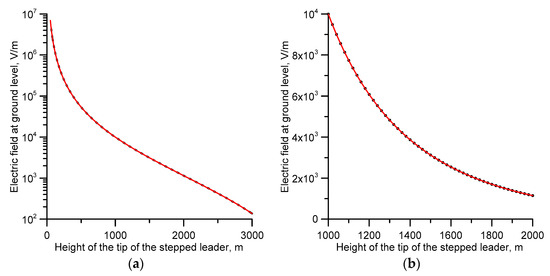
Figure 1.
(a) Electric field at ground level produced by a stepped leader as it moves towards the ground. The solid line (red) depicts the electric field corresponding to a uniformly moving leader and the dashed line (black) corresponding to a leader moving down in 20 m long steps. (b) Section of the expanded electric field change where the solid line (red) shows the electric field due to a continuously moving leader and the data points show the individual jumps in the electric field as the leader extends in steps of 20 m. The prospective return stroke current associated with the stepped leader is 30 kA.
Since the lightning rods are exposed to this background electric field of the stepped leader, the geometry enhanced electric field at the tip of the lightning rods will also follow the temporal variation of the stepped leader field. Therefore, the electric field at the tip of a lightning conductor exposed to the electric field of a down coming stepped leader will also increase in miniature steps in synchronization with the background electric field. Essentially, the behavior of the electric field at the tip of a lightning rod exposed to the stepped leader field is identical to that of a lightning conductor whose tip potential is changed intermittently by applying voltage pulses. The time interval between these pulses is given by the time interval between the leader steps, which lie in the range of 10 μs to about 50 μs. This is exactly what the ESE manufacturers attempt to create artificially. Let us convert the pulsing nature of the electric field at the tip of the lightning rod exposed to the back ground electric field of a stepped leader into an equivalent voltage impulse. This can be done by isolating the lightning rod from the ground by placing it a few millimeters above the ground and calculating the amplitude of the voltage pulses necessary to create electric field steps identical to those produced at the tip of the lightning rod by the stepped leader. The results obtained for a 10 m tall lightning rod with a 5 mm gap to ground are depicted in Figure 2 for a stepped leader associated with a 30 kA prospective return stroke current. The vertical axis gives the amplitude of the equivalent voltage pulse and the horizontal axis depicts the height of the stepped leader tip above the ground. Results are shown for step lengths of 50 m (curve a) and 20 m (curve b).
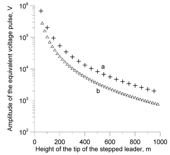
Figure 2.
Amplitude of the voltage pulses that are needed to be applied to the tip of a lightning rod to simulate the electric field changes caused by the stepping process of the stepped leader. (a) 50 m step length. (b) 20 m step length. The prospective return stroke current associated with the stepped leader is 30 kA. The length of the lightning rod is 10 m.
Note that the amplitude of the equivalent voltage pulses increases as the stepped leader nears the ground. The equivalent voltage pulses have amplitudes in the range of kilovolts when the stepped leader is about 1 km above ground and it increases to more than 10 kV when the stepped leader is about 200 m above ground. Observe that leader tip heights below about 500 m are the ones to be considered in connection with lightning attachment because it is at these heights that continuously moving connecting leaders (i.e., stable) are usually issued from lightning conductors located on low structures [11]. Moreover, note that one cannot create a continuously propagating upward connecting leader from lightning rods (either ESE or Franklin) when the stepped leader tip is far away because, in this case, the electric field of the stepped leader is not strong enough to sustain a continuously moving upward connecting leader.
As mentioned earlier, in many ESE lightning rods, the voltage pulses are generated passively by isolating the tip of the rod from the ground. When the lightning rod is exposed to the background electric field created by the stepped leader, the gap (or gaps) fire intermittently generating the voltage pulses. The voltage pulses generated by such a process may have amplitudes in the kV range.
The above analysis indicates that the electric field at the tip of a lightning rod exposed to a stepped leader field pulsates naturally. Any lightning rod in the field will behave as if it has an in-built mechanism to generate voltage pulses that regulate the electric field at its tip. Thanks to the pulsating nature of the stepped leader fields, both the Franklin lightning rods and ESE lightning rods will function in an identical manner when exposed to the electric fields of down coming stepped leaders. There is no need to artificially inject voltage pulses into the tip of a lightning rod because the nature itself generates such pulses, thanks to the stepping mechanism of the stepped leader, without human intervention.
The main claim of ESE technology is that the application of voltage pulses to the tip of the lightning rod will increase its attractive radius. The above analysis shows that, irrespective of the validity of this claim, one still has to treat both ESE lightning rods and Franklin lightning rods as having the same lightning interception efficiency.
3. Discussion on the Assumptions Made in the Study
The charge deposited on a stepped leader channel is transported both by the streamers propagating ahead of the leader tip and by the step current associated with the rapid elongation of the leader channel when the space leader connects with the existing leader channel [6,12]. In the analysis, a simplifying assumption that the bulk of the charge deposited on the stepped leader channel is transported by the step current is made. Let us consider the validity of this assumption. The amplitude of the radiation fields of stepped leaders is about one tenth of the amplitude of return stroke radiation fields [7,8]. Assuming that the speed of development of the leader step and the return stroke is similar, one can estimate using the transmission line model [13] that the current peak associated with the step current of a leader pertinent to a 30 kA return stroke is about 3 kA. If the speed of development of the leader step is smaller than that of the return stroke, the peak current would be higher than the above estimate. Based on such analysis, Cooray and Lundquist [8] came to the conclusion that the charge transported by the step currents can account for the total charge transported by the stepped leader. Using similar considerations, Krider et al. [7] estimated the peak amplitude of step currents to be about 2 kA to 8 kA and the charge transported by the step current to be about 1–4 × 10⁻³ C/m. These charge estimates are close to the charge per unit length transported by steps of dart stepped leaders in rocket triggered lightning [14]. Furthermore, the charge per unit length estimated by Krider et al. [7] is similar to the charge per unit length of stepped leaders obtained by Schonland [15]. These considerations show that the assumption that the bulk of the leader charge is transported by the step current associated with the rapid elongation of the leader channel during the stepping process is not unreasonable.
In order to estimate how much charge is transported during the elongation of the step, it is necessary to know the total distribution of stepped leader charge along its length. In the analysis, this information is obtained from the stepped leader charge distribution as estimated by Cooray et al. [10]. These authors measured the charge brought to ground in return stroke currents recorded by Berger [16] on Mount San Salvatore and combined the results obtained with the bi-directional leader model to evaluate how the charge distribution of stepped and dart leaders vary as these leaders travel towards the ground. The results obtained are validated for subsequent return strokes by comparing the predicted electric fields at a given distance generated by dart leaders as a function of the peak current of the prospective subsequent return strokes and comparing the results with the experimental data obtained for dart leaders in triggered subsequent return strokes. A satisfactory agreement was found between the predictions and the experiments giving credence to the validity of the procedure and the obtained charge distributions. Moreover, the charge distribution obtained in the study were successfully applied in various lightning attachment models and a good agreement is again found between the predictions based on the charge distributions and the experimental observations [17]. For these reasons, we assume that the leader charge distribution used in the present study is reasonable and the results obtained are not far from the ones that would have been obtained if the experiment was carried out in the field.
4. Conclusions
The hallmark of ESE technology is the application of voltage pulses to the tip of the lightning rod assuming that their effects will enhance the attractive radius of the lightning conductor. Analysis presented in this paper shows that any lightning rod when exposed to the electric field produced by a stepped leader will act exactly like an ESE lightning rod because the pulsating electric field of the stepped leader simulates the action of voltage pulses that are being used in ESE lightning rods. It is estimated that the effect of the step-like electric field changes caused by the stepping process of the stepped leader on a lightning rod is equivalent to a voltage source injecting voltage pulses of tens of kV or more at intervals of 10 to 50 μs to the lightning rod. It demonstrates that any possible change in the lightning attachment process caused by the modulation of the electric field at the tip of the rod is common both to ESE and Franklin lightning rods and, therefore, the attachment efficiency of a Franklin lightning rod cannot be different to that of an ESE lightning rod of similar length and geometry.
Funding
The research presented in this paper is supported by the fund from B. John F. and Svea Andersson donation at Uppsala University.
Conflicts of Interest
The authors declare no conflicts of interest.
References
- Berger, G. The early streamer emission lightning rod conductor. In Proceedings of the 15th International Aerospace and Ground Conference on Lightning and Static Electricity, ICOLSE, Atlantic City, NJ, USA, 6–8 October 1992. [Google Scholar]
- Uman, M.A.; Rakov, V. A critical review of non-conventional approaches to lightning protection. Bull. Am. Meteorol. Soc. 2002, 1809–1820. [Google Scholar] [CrossRef]
- Eybert-Berard, A.; Lefort, A.; Thirion, B. Onsite tests. In Proceedings of the 24th International Conference on Lightning Protection, Staffordshire University, Birmingham, UK, 14–18 September 1998; pp. 425–435. [Google Scholar]
- Cooray, V. Non-conventional lightning protection systems (a paper prepared on behalf of the CIGRE working group 405 of study committee C4). Electra 2011, 285, 36–41. [Google Scholar]
- Van Brunt, R.J.; Nelson, T.L.; Stricklett, K.L. Early streamer emission lightning protection systems: An overview. IEEE Electr. Insul. Mag. 2000, 16, 5–24. [Google Scholar] [CrossRef]
- Hill, J.D.; Uman, M.A.; Jordan, D.M. High-speed video observations of a lightning stepped leader. J. Geophys. Res. Atmos. 2011, 116, D16117. [Google Scholar] [CrossRef]
- Krider, E.P.; Weidman, C.D.; Noggle, R.C. The electric fields produced by lightning stepped leaders. J. Geophys. Res. 1977, 82, 951–959. [Google Scholar] [CrossRef]
- Cooray, V.; Lundquist, S. Characteristics of the Radiation Fields from Lightning in Sri Lanka in the Tropics. J. Geophys. Res. 1985, 90, 6099–6109. [Google Scholar] [CrossRef]
- Gallimberti, I. The mechanism of the long spark formation. J. Phys. Colloq. 1979, 40, 193–250. [Google Scholar] [CrossRef]
- Cooray, V.; Rakov, V.; Theethayi, N. The lightning striking distance—Revisited. J. Electrost. 2007, 65, 296–306. [Google Scholar] [CrossRef]
- Cooray, V.; Kumar, U.; Rachidi, F.; Nucci, C.A. On the possible variation of the lightning striking distance as assumed in the IEC lightning protection standard as a function of structure height. Electr. Power Syst. Res. 2014, 113, 79–87. [Google Scholar] [CrossRef]
- Cooray, V.; Arevalo, L. Modeling the Stepping Process of Negative Lightning Stepped Leaders. Atmosphere 2017, 8, 245. [Google Scholar] [CrossRef]
- Uman, M.A.; McLain, D.K. Magnetic field of lightning return stroke. J. Geophys. Res. 1969, 74, 6899–6910. [Google Scholar] [CrossRef]
- Rakov, V.A.; Uman, M.A.; Rambo, K.J.; Fernandez, M.I.; Fisher, R.J.; Schnetzer, G.H.; Thottappillil, R.; Eybert-Berard, A.; Berlandis, J.P.; Lalande, P.; et al. New insights into lightning processes gained from triggered-lightning experiments in Florida and Alabama. J. Geophys. Res. 1998, 103, 14117–14130. [Google Scholar] [CrossRef]
- Schonland, B.F.J. The Lightning Discharge. Handb. Phys. 1956, 22, 576–628. [Google Scholar]
- Berger, K. Methods and results of lightning records at Monte San Salvatore from 1963–1971. Bull. Schweiz. Elektrotech. 1972, 63, 21403–21422. (In German) [Google Scholar]
- Becerra, G.M.; Long, M.; Schulz, W.; Thottappillil, R. On the estimation of the lightning incidence to offshore wind farms. Electr. Power Syst. Res. 2018, 157, 211–226. [Google Scholar] [CrossRef]
© 2018 by the author. Licensee MDPI, Basel, Switzerland. This article is an open access article distributed under the terms and conditions of the Creative Commons Attribution (CC BY) license (http://creativecommons.org/licenses/by/4.0/).