Article

Numerical Simulation of 2-D Solitary Wave Run-Up over Various Slopes Using a Particle-Based Method

1
Department of Naval Architecture and Ocean Engineering, Chosun University, Gwangju 61452, Korea
2
Ship & Ocean R&D Institute, Daewoo Shipbuilding & Marine Engineering Co., Ltd., Siheung 15011, Korea
3
Department of Naval Architecture and Ocean Engineering, Pusan National University, Busan 46241, Korea
*
Author to whom correspondence should be addressed.
Water 2019, 11(3), 462; https://doi.org/10.3390/w11030462
Submission received: 15 January 2019 / Revised: 24 February 2019 / Accepted: 28 February 2019 / Published: 5 March 2019

Abstract

:
The present paper covers the numerical prediction of the propagation and run-up of a solitary wave over non-flat seabed with various slope angles using a refined MPS (moving particle simulation) method. In the refined method, the corrected gradient model, new staggered divergence-free model, moving-particle wall boundary treatment, and the sub-particle scale turbulence model are applied to obtain more stable and precise results. The simulation results by the developed method are compared with experimental results, and both results were in good agreement. Especially, it can be seen that the complicated and fully-nonlinear behavior of the free-surface motion during the turbulent processes of build-up, break-down, and overturning of the waves are well reproduced by the developed method.

1. Introduction

A tsunami, also known as a seismic sea wave, is a series of waves in a water body. These waves are caused by the displacement of a large volume of water, generally in an ocean. As is well known, large events, such as earthquakes, landslides, volcanic eruptions, and other mechanisms, can generate a tsunami. By far, the most destructive tsunamis are generated from large shallow earthquakes with an epicenter or a fault line near or on the ocean floor. When a tsunami occurs and approaches land, waves tens of meters high can be generated. Such waves can have enormous destructive power as seen during the 2011 earthquake off the Pacific coast of Tohoku, Japan [1].
Most of the damage, such as inland flooding and destruction of structures, caused by tsunami are closely related to wave run-up, which is the maximum elevation of the wave above the mean sea level, near the shoreline and its impact on coastal structures. Owing to the hydrodynamic similarities between tsunamis and solitary waves, researchers often use the latter as the initial conditions to investigate the tsunami run-up characteristics [2,3]. For decades, the run-up and inland flooding by solitary waves have been studied through hydraulic experiments. However, it is difficult to obtain experimental data when the wave breaks, and air bubbles and spray are generated. Therefore, various numerical methods have been developed to predict the wave run-up by tsunami. Wave run-up is, however, a complex process involving nonlinear build-up of the wave front, intensive wave breaking, and strong turbulent flow, making numerical simulation challenging.
Several techniques can be used to simulate nonlinear free surface behavior. These techniques include SOLA-VOF (volume-of-fluid) [4], Level-Set [5], and marker-density function [6]. Most of these techniques capture the free surface on the grid system and have been widely used. For both accuracy and stability, various higher-order up-winding schemes are generally employed for the convection terms when using the conventional Eulerian grid-based methods. However, the conventional up-winding schemes, including the addition of artificial diffusion to the central differencing scheme, can often have a decisive influence on the simulation results owing to the smearing of the free surface and nonconservation of the water mass. To overcome these problems, the authors developed a new grid-based multi-phase flow solver, applied this solver for 2-D and 3-D sloshing problems, and showed that the developed solver and particle-based solver, the latter is described in the next paragraph, effectively simulated violent flow behavior [7]. Recently, viscous waves have been simulated numerically by means of FVM (finite volume method) and VOF with good results [8].
On the other hand, meshless methods, also often called particle methods, have become popular, particularly for simulating nonlinear free-surface flows. Representative methods of this approach are smoothed particle hydrodynamics (SPH) [9] and moving particle semi-implicit (MPS) simulation [10]. Because the convection term of the governing equation is directly calculated using the moving particles in the fully Lagrangian approach, numerical diffusion does not occur, and the condition of conservation of mass is perfectly satisfied. However, the particle method suffers from the problem of generation of an unstable fluid flow field because of the temporal and spatial pressure oscillation. Lee, Park, and Kim [11] improved the original moving particle simulation (MPS) and succeeded in reducing this oscillation problem. The effectiveness of the improved method, which is called Pusan-National-University-modified MPS (PNU-MPS), for violent free-surface flows was shown in [7]. There are many other schemes and algorithms developed to stabilize the pressure filed for MPS [12,13,14,15,16,17], and some of them are adopted in the present study.
Solitary waves were numerically reproduced and studied based on SPH [18] and MPS [19]. Dao et al. [20] numerically simulated solitary wave propagation and run-up by using SPH and the Eulerian nonlinear shallow water (Tsunami-N2) numerical models [21]. Comparisons of the simulated wave height time series with the experimental ones showed that Tunami-N2 is suitable only for nonbreaking waves, whereas the SPH method showed full capability to simulate the whole process of wave run-up, including complex wave breaking and tremendous impact pressure. In addition, from the recent numerical studies on solitary wave problems with complicated boundary shapes or the interaction between fluid and a structure [22,23,24], it can be said that the particle method may be more feasible and effective than the conventional grid method.
In the present study, the wave run-ups of solitary waves were numerically studied to investigate the characteristics of tsunami run-up associated with a series of turbulent process of wave breaking and sequential impinging by using the refined PNU-MPS method. In this method, a staggered divergence-free model to stabilize the pressure field and moving-particle wall treatment to satisfy the inclined wall boundary condition was employed for more accurate particle simulation.

2. Numerical Methods

2.1. Governing Equations

For incompressible turbulent flows, the governing equations are the continuity and particle-size averaged Navier–Stokes (N–S) equations as shown in Equations (1) and (2), respectively.
D ρ D t = 0
D u ¯ i D t = 1 ρ p ¯ x i + ν 2 u ¯ i x j 2 ( u i u j ¯ ) x j + F i
where ρ is the density; t , the time; u , the velocity vector; p , the pressure; ν , the kinematic viscosity; and F , the external force vector for unit mass. Subscript i indicates the i -direction component in the Cartesian coordination system x i , and u i u j ¯ is the SPS (Sub-Particle Scale) Reynolds stress term for turbulent flows modelled as [25].
The left-hand side of the N–S equation is directly calculated by the Lagrangian approach. For the MPS simulation, all terms with differential operators should be replaced by the particle interaction models.

2.2. Kernel Function

In the MPS method, the particle interactions are based on a kernel function. In this study, the following kernel function, which is more robust and gives more reasonable results [11] than that used in the original MPS [10], is employed:
w ( | r | ) = { ( 1 | r | r e ) 3 ( 1 + | r | r e ) 3 ( 0 | r | < r e ) 0 ( r e < | r | )
where r is the position vector between two particles and r e represents the effective range of particle interactions. The kernel becomes zero where | r | > r e .

2.3. Gradient Model

A gradient vector between two particles l and m , of which position vectors and scalar quantities are r l , r m and ϕ l , ϕ m , is defined as ( ϕ m ϕ l ) ( r m r l ) / | r m r l | 2 . The gradient vector at particle l is given by the weighted average of these gradient vectors. In this study, the corrected gradient model (4) suggested by [16] and validated in [26] is adopted:
ϕ l = d n 0 m l [ ϕ m ϕ l | r m r l | 2 ( r m r ) C l m w ( | r m r l | ) ] C l m = ( V l m w l m x l m 2 r l m 2 V l m w l m x l m y l m r l m 2 V l m w l m x l m y l m r l m 2 V l m w l m y l m 2 r l m 2 ) 1 , V l m = d l m w l m
where C l m is a corrective matrix to ensure the first-order completeness of the gradient model. V l m and w l m are a statistical volume of particle l and a kernel function where the distance between two particles l and m is r l m ( = ( x l m 2 + y l m 2 ) 1 / 2 = | r m r l | ) . Further, d is the number of space dimensions, and n 0 is the fixed particle number density for the incompressibility of the initial particle arrangement condition. The particle number density is calculated using the following equation.
n l = m l w ( | r m r l | )

2.4. Laplacian Model

Owing to its simplicity, the original Laplacian model [10] is adopted in the present study, even though improved Laplacian models for the MPS method were recently proposed [12,13,15]. The diffusion of ϕ at particle l is described as follows:
2 ϕ l = 2 d λ n m l ( ϕ m ϕ l ) w ( | r m r l | )
λ = m l w ( | r m r l | ) | r m r l | 2 m l w ( | r m r l | ) V w ( r ) r 2 d v V w ( r ) d v
where λ is the parameter that makes the increase in variance equal to that of the analytical solution.

2.5. Incompressibility Model with a Staggered Divergence-Free Model

Fluid density is represented by the particle number density. Thus, the continuity equation shown in Equation (1) is fulfilled by maintaining the particle number density through the simulation. This means that the particle number density n 0 should be constant.
The algorithm of incompressibility for the PNU-MPS method [11] is similar to that of the SMAC (simplified marker-and-cell) method in the grid system. Each time step involves two stages: in the first stage, the temporary velocity components u l * of particle l are obtained using the viscous terms, external forces, and convection terms, which are explicitly calculated using the values u l n and r l n in the n -th time step.
In the second stage, the Poisson equation for pressure is calculated implicitly as suggested by Tanaka and Masunaga [14].
2 p l n + 1 = ρ Δ t u l * + γ ρ Δ t 2 n 0 n l n n 0
The blending parameter γ of the right-hand side of Equation (8) is less than 1.0, and the range 0.01 < γ < 0.05 is recommended in [11], while an alternative Poisson equation with dynamic coefficients for error-compensating terms was proposed by [16].
The left-hand side of Equation (8) is discretized by the Laplacian model shown in Equation (6). The first source term in Equation (8) is the divergence-free condition and is calculated by the following equation in the original MPS method [10]:
u l = d n 0 m l ( u m u l ) ( r m r l ) | r m r l | 2 w ( | r m r l | )
To calculate divergence of flow-fields more accurately, a new divergence model, in which velocity components are arranged on a staggered-mesh in a grid-based sense, was introduced in the present study. As shown in Figure 1, a virtual control volume is generated around each particle, and the divergence at particle l can be calculated by Equation (10) using the staggered velocity components estimated by Equation (11) at each control surface.
u l = u 1 E u 1 W 2 l 0 + u 2 N u 2 S 2 l 0
u 1 E = ( u 1 ) w ( | r E r j | ) / w ( | r E r j | ) , u 1 W = ( u 1 ) w ( | r W r j | ) / w ( | r W r j | ) u 2 N = ( u 2 ) w ( | r N r j | ) / w ( | r N r j | ) , u 2 S = ( u 2 ) w ( | r S r j | ) / w ( | r S r j | )
where l 0 is the particle size, and subscripts E , W , N , and S indicate the centers of the east, west, north, and south control surfaces, respectively, around particle l .
The second source term in Equation (8) is represented by the deviation of the particle number density from the constant, and it implies that the particle number densities should be maintained during the simulation.
Here, Equation (8) presents simultaneous equations expressed by a linear symmetric matrix; they are solved by the iteration method. In the present study, the conjugate gradient method is employed as the iterative solver.
After updating the pressure field, the velocity correction u l is calculated by the following equation:
u l = Δ t ρ p l n + 1
Finally, the velocity components and coordinates of particles in the ( n + 1 )-th time step are calculated from the following equations:
u l n + 1 = u l * + u l
r l n + 1 = r l n + Δ t u l n + 1

2.6. Boundary Conditions

2.6.1. Free-Surface Boundary Condition

Kinematic and dynamic boundary conditions are imposed on the free-surface particles. The kinematic boundary condition can be directly satisfied by moving particles on the free surface. In the present method, it is straightforward to track the free-surface particles because the location of the free surface is easily obtained through a fully Lagrangian treatment of particles.
In the vicinity of the free surface, the particle number densities decrease because of the air region, where no particles exist in case of a single-phase problem. Thus, on the free surface, the particles satisfying the following simple conditions are considered:
n l < β 1 n 0
N l < β 2 N 0
where β 1 and β 2 are parameters less than 1.0; N l , the number of neighboring particles within the effective range of particle interaction r e , and N 0 , the maximum number of neighboring particles for fully submerged particles in the initial distribution, i.e., 12 particles for 2D computation when r e is set to 2.1. In particular, the free-surface parameters β are used to judge whether the particles are on the free surface, and β 1 and β 2 are set at 0.91 and 0.86, respectively, in this study; these values are different from those used in [11]. By using this free-surface boundary condition, the fragmentation and coalescence of free-surface flow was simulated.
Assuming that there is no viscosity at the free surface, the dynamic free-surface boundary condition is satisfied by taking the atmosphere pressure ( p = p a t m = 0 ) on the free-surface particles. This condition is fulfilled in the procedure of solving Poisson equation (Equation (8)).

2.6.2. Wall Boundary Condition

For the wall boundary condition, the fixed wall particles are set along the solid boundary in both the original MPS [10] and PNU-MPS methods. Dummy particles are placed inside the solid wall instead of being identified as free-surface particles. The wall particles are in direct contact with both the fluid particles and dummy particles. They are employed in the pressure calculation to avoid concentration of particles near the wall. To satisfy the no-slip condition, the velocity of wall particles is set as zero. The velocity of the dummy particles is considered in the same manner as that of the dummy cells in the grid method, and the pressure of those is set as zero.
However, if the wall boundary slopes, it is represented as stepped shape, which may decrease the accuracy of the simulation, as shown in Figure 2a. To impose a more accurate wall boundary condition and to reduce computational time, a moving-particle wall boundary condition was adopted in the present research. In the method, ghost particles are placed symmetrically on the virtual wall boundary to calculate the velocity and pressure of the fluid particles near the boundary as shown in Figure 2b. The velocity of the ghost particle is considered in the same manner as that of the dummy cells in the grid method, i.e., the ghost particle’s velocity components normal and tangential to the wall are opposite values of corresponding fluid particle for the no-slip condition on the wall. The hydrostatic pressure of the ghost particles is adjusted when a free surface exists.

2.7. Turbulence Model

In the sub-grid scale (SGS) turbulence model for large eddy simulation (LES), eddies that can be resolved by the computational grid are allowed to evolve according to the N–S equations and a model is employed to represent the turbulence at the SGS by a particle-based method. The unresolved third term in the right-hand side of Equation (2) is considered the SPS Reynolds stress and is modeled as shown in Equation (15) [25].
u i u j ¯ = 2 ν t S i j 2 3 k δ i j
where δ i j , S i j = 1 / 2 ( u ¯ j / x i + u ¯ i / x j ) , and k are the Kronecker’s delta, strain rate, and turbulent kinetic energy, respectively.
The widely used Smagorinsky model [27] is employed here to formulate the turbulence eddy viscosity as follows:
ν t = ( C s Δ ) 2 | S i j ¯ |
where C s is the Smagorinsky constant (taken as 0.1 in the computations), Δ is the particle-to-particle spacing (the equivalent of mixing length in a grid method), and | S i j ¯ | is the local strain rate which can be calculated from the resolved variables.

3. Numerical Simulations and Discussion

3.1. Hydrostatic Pressure Test

First, the numerical models explained in the previous section are applied to the static pressure problem inside a rectangular tank (Figure 3). The width and water depth of the tank are 0.4 m and 0.4 m, respectively, and 1700 particles, of which 1600 are water particles, are used for the simulation. The total computational time is 3 s. The gravitational acceleration g is 9.81 m/s2, and water density is 1000 kg/m3. Viscous effects are included.
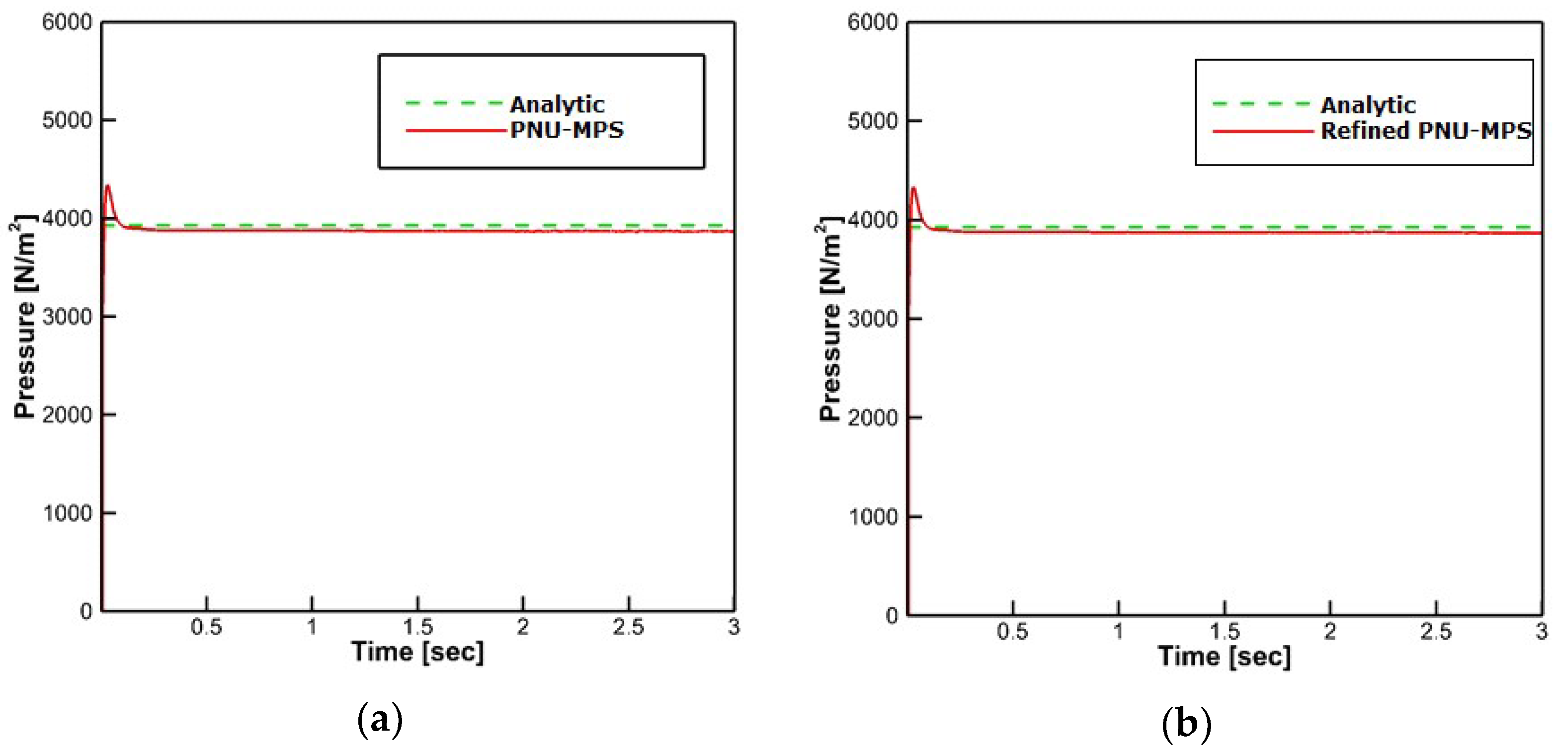
Figure 4 shows the pressure fields simulated by the PNU-MPS method and the refined MPS method adopting the staggered divergence-free model and the moving-particle wall boundary treatment. As shown in the figure, no unnatural pressure oscillation was observed at least for the hydrostatic pressure test by the refined PNU-MPS method (Figure 4b), even though there was no big discrepancy in the time-histories of hydrostatic pressure probed at P1, i.e., bottom center position, by the two methods as shown in Figure 5.

3.2. Solitary Wave Run-Up (Constant Slope Angles)

As a preliminary test, solitary wave run-ups in a tank with a bottom of constant slope angle were simulated under the same experimental conditions as those of Hall and Watts [28]. As shown in Figure 6, a piston-type wavemaker is located on the left side of the numerical wave tank. Here, L is the distance from the wavemaker, and then a flat bottom is followed by a constant slope angle θ . In the figure, H and h are the maximum wave height and water depth, respectively. Simulation conditions are listed in Table 1.
To generate the target wave, the wave-maker moves in the horizontal direction, following Equation (19).
X ( t ) = H k 0 h tanh ( C t X 0 )
where k 0 ( = 3 H / 4 h 3 ) and C ( = g ( h + H ) ) are wave-number and wave-velocity, respectively.
By applying Newton’s law [29], Equation (19) can be discretized as Equation (20), and the stroke of wavemaker S is expressed as shown in Equation (21).
X n + 1 = X n F ( X n ) d F ( X n ) / d X
S = 16 H h / 3
To investigate the influence of particle size on the results, numerical simulations were carried out with varying particle size for the case of a slope angle of 90°. Figure 7 shows the maximum run-up R , which is nondimensionalized by water depth h , measured on the vertical wall with respect to the change in particle size. As the wave height ratio H / h increases, the results are affected to a greater extent by particle size. The simulated solitary wave profile for H / h = 0.3 was compared with the analytic solution in Figure 8 where good agreement is shown. Furthermore, no severe oscillation is observed in the dynamic pressure fields which are more sensitive than total pressure fields. Based on the results and the computation time, a particle size of 0.0025 mm was chosen for further simulations.
The maximum run-up estimated by the present method showed good agreement with the experimentally measured values [28] as shown in Figure 9.
The estimated run-ups for a slope angle of 45° are compared with those obtained by experiments [28], run-up law (Equation (22)) [30] and numerical simulations using boundary integral equation method (BIEM) [31], as shown in Figure 10. The tendency and the value of the estimated run-up obtained by the BIEM are different from those determined experimentally; even the simple theoretical law shows tendency similar to the experimental results. On the contrary, the present method can estimate the run-ups very well.
R / h = 2.831 cot θ 1 / 2 ( H / h ) 5 / 4
As shown in Figure 11, the estimated run-ups by the present method and the run-up law show tendencies similar to the experimental ones [3] for a slope angle of 26°.
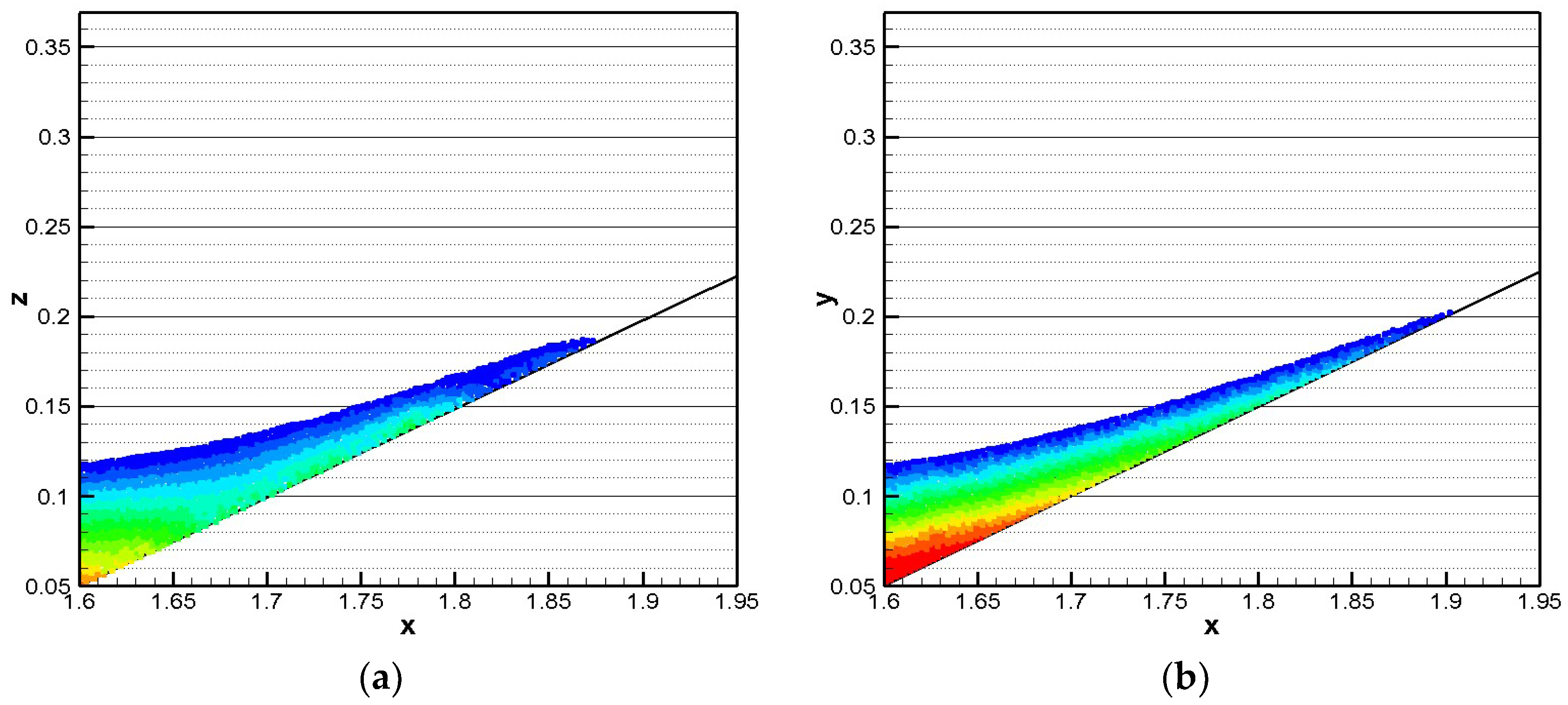
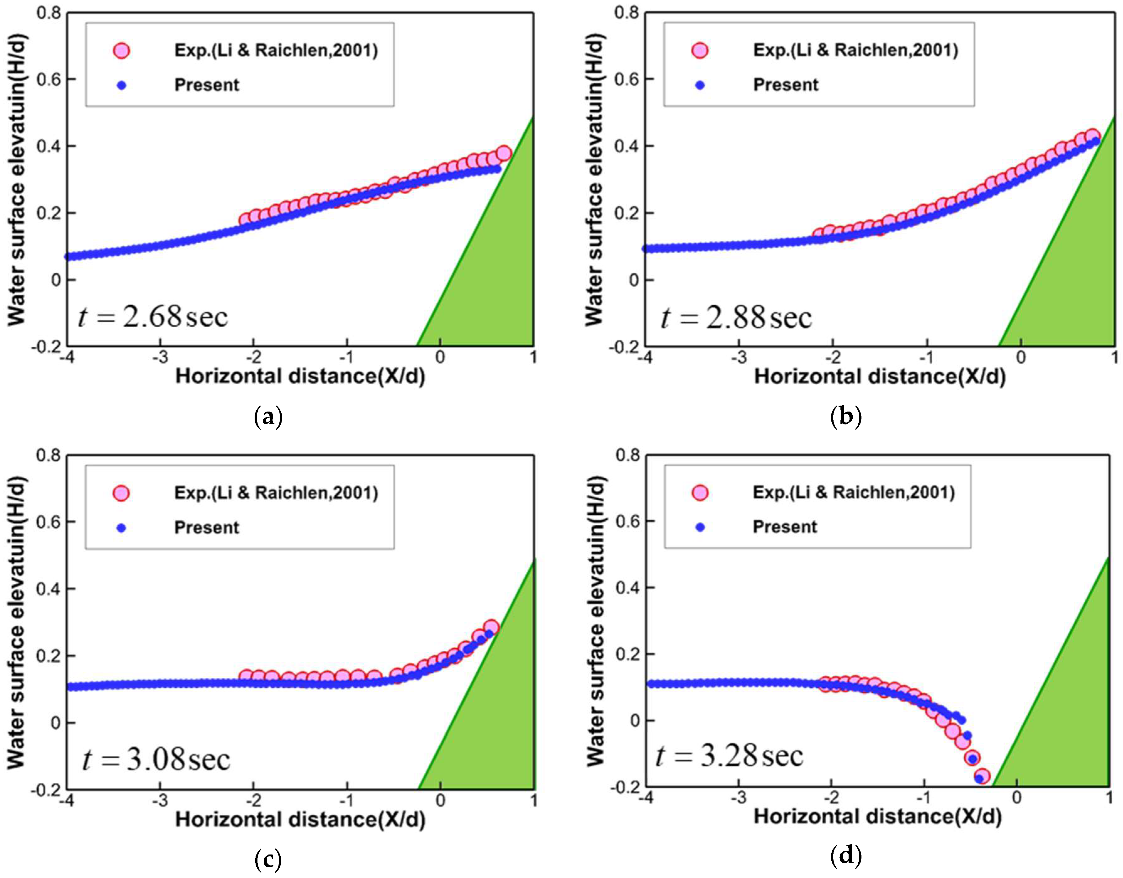
To investigate the influence of moving-wall boundary treatment, which was newly developed and adopted in the present study, on the computational results, numerical simulations with adopting fixed-particle wall boundary conditions were also carried out. Figure 12 shows the comparison of wave run-up profile over a slope angle of 26° in case of H / h = 0.35, simulated by (a) fixed- and (b) moving-particle wall treatments previously explained in the chapter 2.6.2. As clearly seen in the figure, the estimated maximum run up by adopting moving-particle wall treatment, which shows good agreement with those of experiment and run-up law, is approximately 10% higher than that by fixed-particle wall treatment. In Figure 13, the time-sequential wave profiles of present computational results adopting moving-wall boundary treatment are compared with experimental ones [3] over a slope of 26° in case of H / h = 0.163. Two results are in good agreement.

3.3. Solitary Wave Run-Up (Varying Slope Angle)

Considering a more realistic case, numerical experiments were conducted under the same experimental conditions [32] as those shown in Figure 14. The numerical wave tank consisted of a wave-maker located at the left side of the tank, a flat bottom followed by three slopes (1:53, 1:150, and 1:13) and a vertical wall located at the right side. Still water depth in the flat section was d = 0.218 m. Four wave gauges were distributed in the flume to measure surface elevation.
In the simulations, two different solitary waves were generated by the movement of the piston-type wave-maker. The target wave height h w a v e / h were 0.3 (case 1) and 0.7 (case 2). The horizontal displacement and velocities of the paddle were expressed by Equations (23) and (24), respectively. Further, the used coefficients for the cases are listed in Table 2.
S p = A 1 tanh [ A 2 ( t ) A 3 ] A 4
U p = A 1 A 2 sec h 2 [ A 2 ( t ) A 3 ]
First, the solitary wave in case 1 was numerically reproduced with varying particle size to check its effect on the simulation results. The sizes of the simulations were 0.005 m and 0.0025 m; the corresponding total numbers of the particles were 84,941 and 339,795, respectively.
Comparisons of time histories of wave height at gauges as obtained from numerical simulations and experiment are shown in Figure 15. The incident and reflecting waves from the simulations with two sizes of particles agree well with the experimental results for all gauges, except gauge 4 where the wave height measured in the experiment decreases while that obtained in the simulation does not decrease. Further, smaller particles showed slightly better results after reflection.
The snapshots of free-surface shapes with the distribution of turbulent kinetic energy are shown in Figure 16. The solitary wave propagates and steepens (Figure 16a) and starts to break (Figure 16b) at gauge 2 where the slope of the bottom is 1:55. From Figure 16c, it is found that wave-breaking already occurred between gauges 2 and 3 and continued to propagate forward to the wall on the right. In addition, the wave-breaking repeatedly occurs at gauges 3 and 4 where the slope of the bottom is 1:150 and 1:13, respectively. The wave front is composed by water sprays splashing forward instead of a sharp interface (Figure 16c,d). On the whole, the breaking wave hits the wall, water splashes upward, and the water elevation at the wall increases quickly; the main part of the reformed wave impacts on the wall and creates an upward water jet (Figure 16e). Unlike case1, the wave height of reflecting wave near gauge 4 (Figure 16f) is higher than that of incoming wave (Figure 16d). This is probably resulted from that the splashed water overturned after hitting the wall (Figure 16e) and impinged to the free-surface near gauge 4.
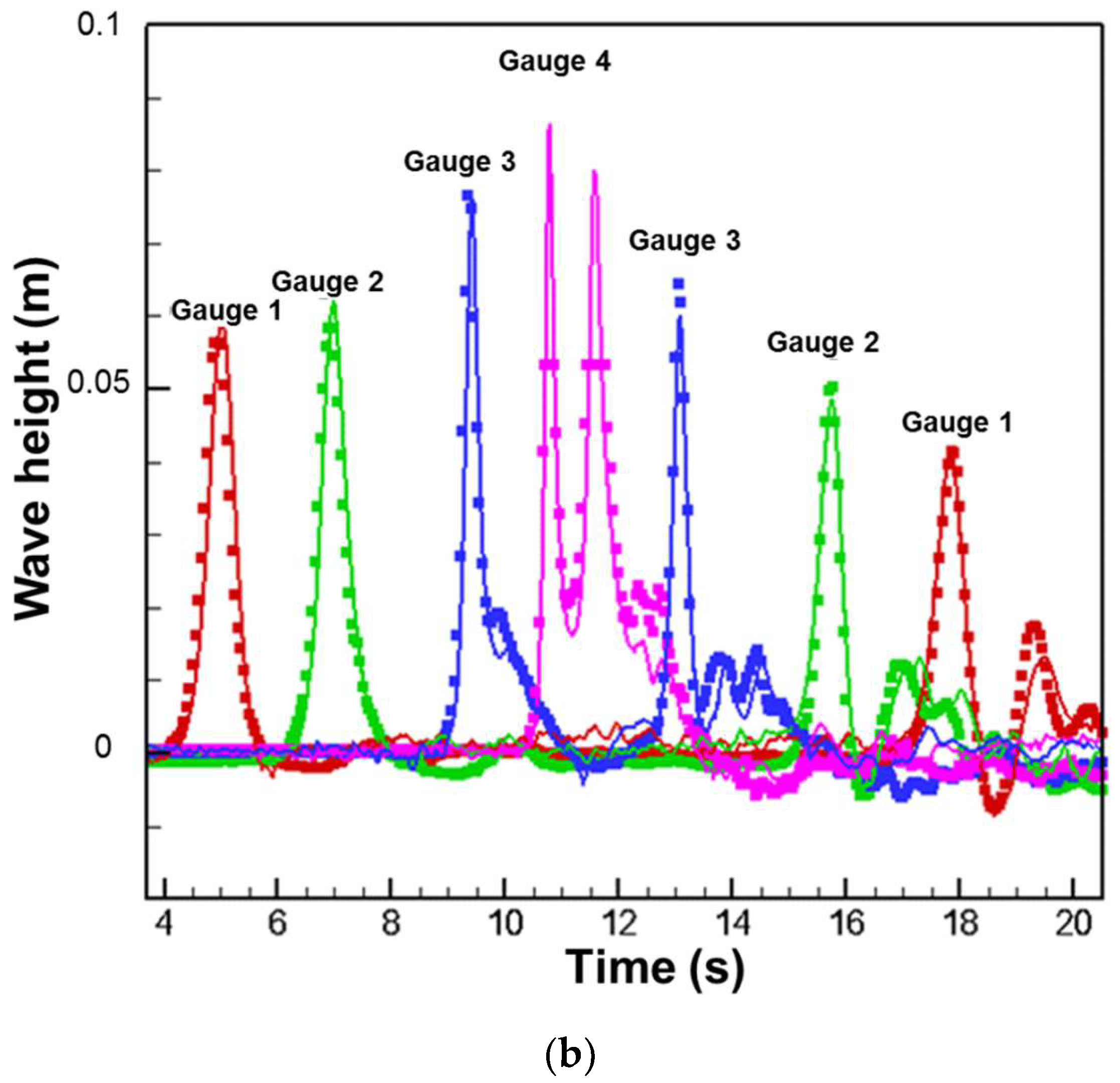
Comparisons of time histories of wave height measured at gauges obtained from the simulations and experiment are shown in Figure 17. The wave steepens when passing by gauge 2, as the wave height ratio H / h increases because of the decrease in the water depth. The incident wave heights measured at these gauges from the present simulation match the experimental data well. Wave breaking is confirmed to occur somewhere between gauges 2 and 3 as sharp drops in wave heights are observed in both numerical and experimental results. Although the incident wave is almost twice that of case 1, the ratio of the maximum run-up height over the still water depth is lower. This can be attributed to the large amount of the wave momentum that was dissipated through the breaking before the wave hits the wall. Despite some discrepancies, good agreements are also observed between the numerical and experimental data of the reflected waves except at gauge 4 where the interactions among the incoming waves, reflecting waves, and returning fluids after hitting the vertical wall are very complicated. Numerical investigations on the wave-breaking modeling involving free surface turbulence model are needed to be introduced in near future.

4. Conclusions

In the present study, numerical studies on the propagation and run-up of the solitary wave were carried out to investigate the characteristics of run-up by tsunamis using the refined PNU-MPS method by applying the corrected gradient model, new staggered divergence-free model, moving-particle wall boundary treatment, and SPS turbulence model. By adopting the newly-developed divergence model with moving-wall boundary treatment, very smooth pressure fields were obtained both for hydro-static test and run-up simulations. The simulation results for wave run-ups were compared with those obtained by experiment and analytic solution, which were in good agreement. It can be said that the present method showed full capability to simulate the whole process of wave run-up, including complex wave breaking with high accuracy.

Author Contributions

Conceptualization, J.-I.P. and J.-C.P.; Methodology, S.-M.J., J.-I.P. and J.-C.P.; Software, S.-M.J. and J.-I.P.; Validation, J.-I.P.; Formal Analysis, J.-I.P.; Investigation, J.-I.P.; Resources, J.-C.P.; Data Curation, J.-I.P.; Writing—Original Draft Preparation, S.-M.J. and J.-C.P.; Writing—Review and Editing, S.-M.J. and J.-C.P.; Visualization, J.-I.P.; Supervision, S.-M.J. and J.-C.P.; Project Administration, J.-C.P.; Funding Acquisition, J.-C.P.

Funding

This research was supported by Basic Science Research Program through the National Research Foundation of Korea (NRF) funded by the Ministry of education [No. 2015R1D1A1A01].

Conflicts of Interest

The authors declare no conflict of interest.

Nomenclature

A 1 , A 2 , A 3 , A 4 coefficients for making target wave (-)
C wave-velocity (ms−1)
C l m corrective matrix for gradient model (-)
C s Smagorinsky constant (-)
d number of space dimensions (-)
F external force for unit mass (ms−2)
E , W , N , S centers of the east, west, north, and south control surfaces of particle l (-)
g gravitational acceleration (ms−2)
h water depth (m)
H maximum wave height (m)
i i -direction component in the Cartesian coordination system x i (-)
k turbulent kinetic energy (m2s−2)
k 0 wave-number (m−1)
l or m particle index (-)
l 0 particle size (m)
n time step index (-)
n 0 fixed particle number density for the incompressibility (-)
n l particle number density of particle l (-)
N 0 maximum number of neighboring particles in the initial distribution (-)
N l number of neighboring particles of particle l (-)
p pressure (Pa)
r position vector between two particles (m)
r e effective radius for particle interactions (m)
r l , r m position vector of particle l and m (m)
r l m relative position vector between particle l and m (m)
r l m distance between particle l and m [ = ( x l m 2 + y l m 2 ) 1 / 2 = | r m r l | ] (m)
R wave run-up (m)
S i j strain rate (-)
S p stroke of wavemaker’s paddle (cm)
t time (s)
u velocity vector (ms−1)
u l * temporary velocity components of particle l (ms−1)
u l velocity correction of particle l (ms−1)
u i u j ¯ Reynolds stress term for turbulent flows (m2s−2)
V l m statistical volume of particle l (-)
U p speed of wavemaker’s paddle (cms−1)
w ( ) kernel function (-)
w l m kernel function between particle l and m [ = w ( | r m r l | ) ] (-)
x l m distance between particle l and m in the x-direction (m)
X ( t ) position of wave-maker at time t (m)
y l m distance between particle l and m in the y-direction (m)
Z height of wavemaker’s paddle (m)
β 1 , β 2 parameters for detecting free surface (-)
δ i j Kronecker’s delta (-)
Δ particle-to-particle spacing (m)
ϕ l m difference of scalar quantities ϕ between particle l and m (m)
ϕ l , ϕ m scalar quantities ϕ at particles l and m (-)
γ blending parameter for incompressibility model (-)
λ parameter that makes the increase in variance equal to that of the analytical solution (-)
θ slope angle of bottom (°)
ρ density (kgm−3)
ν kinematic viscosity (m2s−1)
ν t eddy viscosity (m2/s−1)

References

  1. Mimura, N.; Yasuhara, K.; Kawagoe, S.; Yokoki, H.; Kazama, S. Damage from the Great East Japan Earthquake and Tsunami—A quick report. Mitig. Adapt. Strateg. Glob. Chang. 2011, 16, 809–818. [Google Scholar]
  2. Camfield, F.E.; Street, R.L. Shoaling of solitary waves on small slopes. J. Waterw. Harb. Div. 1969, 95, 1–22. [Google Scholar]
  3. Li, Y.; Raichlen, F. Solitary wave runup on plane slopes. J. Waterw. Portcoastaland Ocean Eng. 2001, 127, 33–44. [Google Scholar] [CrossRef]
  4. Hirt, C.W.; Nichols, B.D. Volume of fluid (VOF) method for the dynamics of free boundaries. JCP 1981, 39, 201–225. [Google Scholar] [CrossRef]
  5. Sussman, M.; Smereka, P.; Osher, S. A level set approach for computation solutions to incompressible two-phase flow. JCP 1981, 114, 272–280. [Google Scholar]
  6. Miyata, H.; Park, J.C. Chapter 5 wave breaking simulation. In Potential Flow of Fluids; M. Rahman Computational Mechanics Publications; WIT Press/Computational Mechanics: Southampton, UK, 1995; pp. 149–176. [Google Scholar]
  7. Jeong, S.M.; Hwang, S.C.; Park, J.C. Numerical Simulation of Impact Loads Caused by Sloshing in a Rectangular Tank Using Eulerian and Lagrangian Approaches. Int. J. Offshore Polar Eng. 2014, 24, 174–180. [Google Scholar]
  8. Alfonsi, G.; Lauria, A.; Primavera, L. Recent results from analysis of flow structures and energy modes induced by viscous wave around a surface-piercing cylinder. Math. Probl. Eng. 2017, 2017, 5875948. [Google Scholar] [CrossRef]
  9. Monaghan, J.J. An introduction to SPH. Comput. Phys. Commun. 1988, 48, 89–96. [Google Scholar] [CrossRef]
  10. Koshizuka, S.; Oka, Y. Moving-particle semi-implicit method for fragmentation of incompressible fluid. Nucl. Sci. Eng. 1996, 123, 421–434. [Google Scholar] [CrossRef]
  11. Lee, B.H.; Park, J.C.; Kim, M.H.; Hwang, S.C. Step-by-step improvement of MPS method in simulating violent free-surface motions and impact-loads. J. Comput. Methods Appl. Mech. Eng. 2011, 200, 1113–1125. [Google Scholar] [CrossRef]
  12. Zhang, S.; Morita, K.; Fukuda, K.; Shirakawa, N. An improved MPS method for numerical simulations of convective heat transfer problems. Int. J. Numer. Methods Fluids 2006, 51, 31–47. [Google Scholar] [CrossRef]
  13. Khayyer, A.; Gotoh, H. A higher order Laplacian model for enhancement and stabilization of pressure calculation by the MPS method. Appl. Ocean Res. 2010, 32, 124–131. [Google Scholar] [CrossRef]
  14. Tanaka, M.; Masunaga, T. Stabilization and smoothing of pressure in MPS method by Quasi-Compressibility. J. Comput. Phys. 2010, 229, 4279–4290. [Google Scholar] [CrossRef]
  15. Khayyer, A.; Gotoh, H. A 3D higher order Laplacian model for enhancement and stabilization of pressure calculation in 3D MPS-based simulations. Appl. Ocean Res. 2012, 37, 120–126. [Google Scholar] [CrossRef]
  16. Khayyer, A.; Gotoh, H. Enhancement of stability and accuracy of the moving particle semi-implicit method. J. Comput. Phys. 2011, 23, 3093–3118. [Google Scholar] [CrossRef]
  17. Koh, C.; Luo, M.; Gao, M.; Bai, W. Modelling of liquid sloshing with constrained floating baffle. Comput. Struct. 2013, 122, 270–279. [Google Scholar] [CrossRef]
  18. Lo, E.Y.; Shao, S. Simulation of near-shore solitary wave mechanics by an incompressible SPH method. Appl. Ocean Res. 2002, 24, 275–286. [Google Scholar]
  19. Imanian, H.; Kolahdoozan, M.; Zarrati, A.R. Waves simulation in viscous waters using MPS. In Proceedings of the 2011 IEEE 3rd International Conference on Communication Software and Networks (ICCSN), Xi’an, China, 27–29 May 2011; pp. 264–268. [Google Scholar]
  20. Dao, M.H.; Xu, H.; Chan, E.S.; Tkalich, P. Modelling of tsunami-like wave run-up, breaking and impact on a vertical wall by SPH method. Nat. Hazards Earth Syst. Sci. 2013, 13, 3457–3467. [Google Scholar] [CrossRef]
  21. Goto, C.; Ogawa, Y.; Shuto, N.; Imamura, F. Numerical Method of Tsunami Simulation with the Leap-Frog Scheme (IUGG/IOC Time Project); IOC Manual No. 35; UNESCO: Paris, France, 1997. [Google Scholar]
  22. Wei, Z.; Dalrymple, R.A.; Rustico, E.; Hérault, A.; Bilotta, G. Simulation of Nearshore Tsunami Breaking by Smoothed Particle Hydrodynamics Method. J. Waterw. Port Coast. Ocean Eng. 2016, 142, 05016001. [Google Scholar] [CrossRef]
  23. Aristodemo, F.; Tripepi, G.; Meringolo, D.D.; Veltri, P. Solitary wave-induced forces on horizontal circular cylinders: Laboratory experiments and SPH simulations. Coast. Eng. 2017, 129, 17–35. [Google Scholar] [CrossRef]
  24. Ren, Y.; Luo, M.; Lin, P. Consistent Particle Method Simulation of Solitary Wave Interaction with a Submerged Breakwater. Water 2019, 11, 261. [Google Scholar] [CrossRef]
  25. Gotoh, H.; Shibahara, T.; Sakai, T. Sub-particle-scale turbulence model for the MPS method—Lagrangian flow model for hydraulic engineering. Adv. Methods Comput. Fluid Dyn. 2001, 9, 339–347. [Google Scholar]
  26. Jeong, S.M.; Nam, J.W.; Hwang, S.C.; Park, J.C.; Kim, M.H. Numerical prediction of oil amount leaked from a damaged tank using two-dimensional moving particle simulation method. Ocean Eng. 2013, 69, 70–78. [Google Scholar] [CrossRef]
  27. Smagorinsky, J. General circulation experiments with the primitive equations: I. the basic experiment. Mon. Weather Rev. 1963, 91, 99–164. [Google Scholar] [CrossRef]
  28. Hall, J.V.; Watts, G.M. Laboratory Investigation of the Vertical Rise of Solitary Waves on Impermeable Slopes; Beach Erosion Board; US Army Corps of Engineers: Washington, DC, USA, 1953; Technical Memorandum 33. [Google Scholar]
  29. Hughes, S.A. Physical Models and Laboratory Techniques in Coastal Engineering; World Scientific: Singapore, 1993; p. 7. [Google Scholar]
  30. Synolakis, C.E. The runup of solitary waves. J. Fluid Mech. 1987, 185, 523–545. [Google Scholar] [CrossRef]
  31. Kim, S.K.; Liu, P.L.F.; Liggett, J.A. Boundary integral equation solutions for solitary wave generation, propagation and run-up. Coast. Eng. 1983, 7, 299–317. [Google Scholar] [CrossRef]
  32. Briggs, M.J.; Synolakis, C.E.; Kanoglu, U.; Creen, D.R. Runup of solitary waves on a vertical wall. In Long-Wave Runup Models, Proceedings of the International Workshop, Friday Harbor, USA; World Scientific Pub Co. Inc.: Hackensack, NJ, USA, 1995. [Google Scholar]
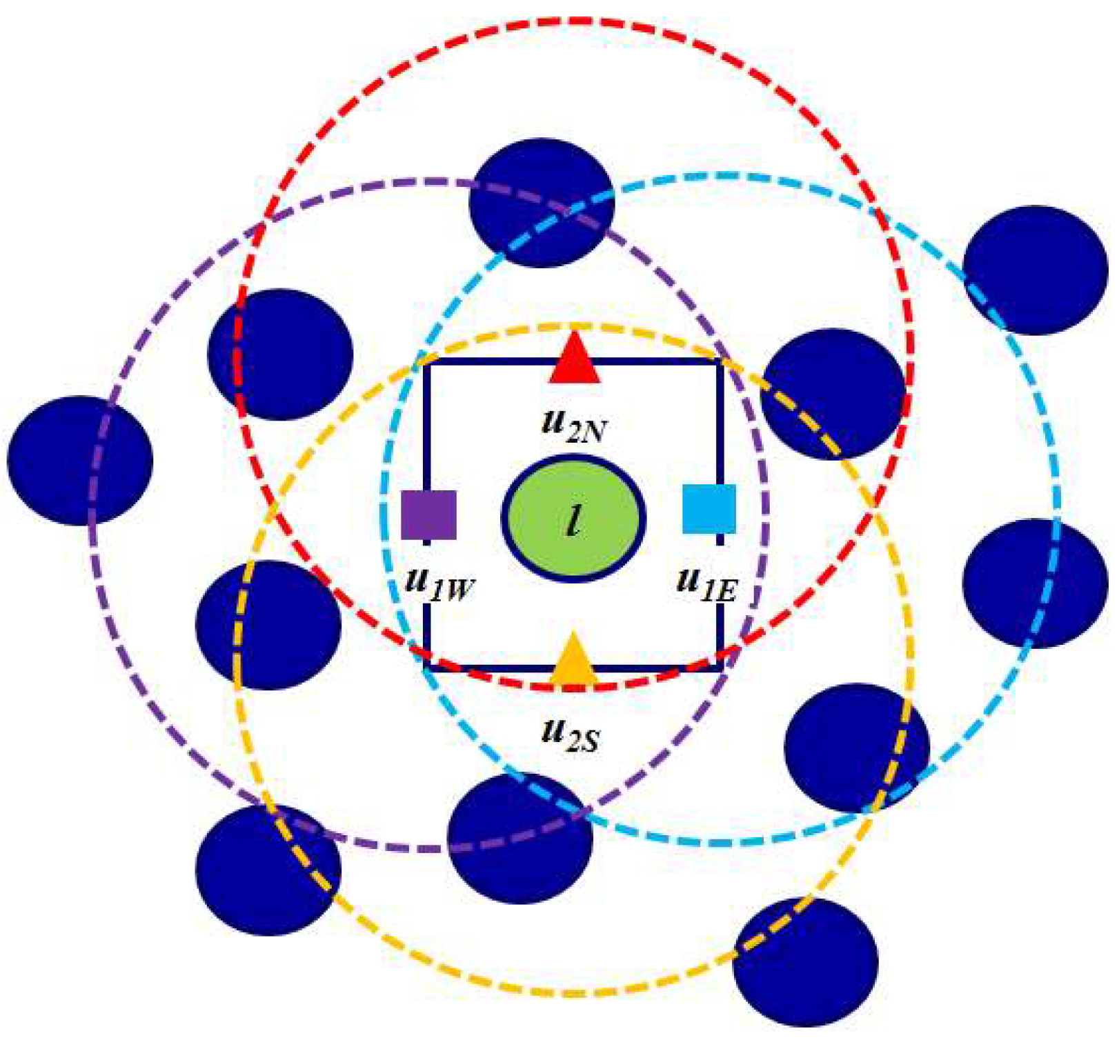
Figure 1. Schematic view of the staggered divergence-free model.
Water 11 00462 g001
Figure 2. Schematic view of (a) fixed- and (b) moving-particle wall boundary treatment.
Water 11 00462 g002
Figure 3. Set-up for a hydraulic pressure test simulation.
Water 11 00462 g003
Figure 4. Comparison of the pressure field simulated by the (a) Pusan-National-University-modified moving particle simulation (PNU-MPS) and (b) present refined PNU-MPS adopting the staggered divergence-free model and the moving-particle wall boundary treatment after 3 s of simulations.
Water 11 00462 g004
Figure 5. Time-histories of hydrostatic pressure proved at P1, which are simulated by the (a) PNU-MPS and (b) present refined PNU-MPS adopting the staggered divergence-free model and the moving-particle wall boundary treatment
Water 11 00462 g005
Figure 6. Set-up for solitary wave run-up on the bottom with constant slope angle.
Water 11 00462 g006
Figure 7. Convergence tests of particle size for the maximum run-up (constant slope angle = 90°).
Water 11 00462 g007
Figure 8. Simulated solitary wave profile compared with analytic solution and distribution of dynamic pressure for wave height ratio H/h = 0.3 (constant slope angle = 90°).
Water 11 00462 g008
Figure 9. Comparison of the maximum run-up (constant slope angle = 90°).
Water 11 00462 g009
Figure 10. Comparison of the maximum run-up (constant slope angle = 45°).
Water 11 00462 g010
Figure 11. Comparison of the maximum run-up (constant slope angle = 26°).
Water 11 00462 g011
Figure 12. Comparison of wave run-up profile over a slope of 26° in case of H/h = 0.35, simulated by (a) fixed- and (b) moving-particle wall treatments.
Water 11 00462 g012
Figure 13. Comparison of time-sequential wave profiles estimated by present simulation and measured by experiment over a slope of 26° in case of H/h = 0.163 at (a) t = 2.68 s, (b) t = 2.88 s, (c) t = 3.28 s, and (d) t = 3.08 s.
Water 11 00462 g013
Figure 14. Set-up for solitary wave run-up on the bottom with varying slope angle.
Water 11 00462 g014
Figure 15. Time history of wave height for case 1 with particle sizes of (a) 0.005 m and (b) 0.0025 m (solid lines: numerical simulated results, symbols: hydraulic experiments).
Water 11 00462 g015aWater 11 00462 g015b
Figure 16. Time-sequence of turbulent intensity field during wave run-up process including wave breaking and impinging over a vertical slope for case 2.
Water 11 00462 g016aWater 11 00462 g016b
Figure 17. Time history of wave height for case 2 with particle sizes of 0.005 m (solid lines: numerical simulated results, symbols: hydraulic experiments).
Water 11 00462 g017
Table 1. Simulation conditions.
L (m)Z (m)h (m)θ (°)l0 (m)H/h (-)
1.50.30.1900.00125, 0.0025, 0.005, 0.0100.1, 0.2, 0.3, 0.4, 0.5,0.6
450.00250.05, 0.1, 0.2, 0.3, 0.4, 0.5
260.15, 0.163, 0.2, 0.25, 0.3, 0.35
Table 2. Parameters for generating solitary waves.
CaseBreakingTarget Wave Height (-)A1 (-)A2 (-)A3 (-)A4 (-)
10.312.852.939.42−12.85
2O0.719.634.36812.25−19.63