1. Introduction
The rapid development of swath acoustic techniques has enabled seabed mapping at high spatial resolutions and accuracies. The results of the high-resolution acoustic technologies, such as multibeam echosounder (MBES) bathymetry, MBES backscattering, sub-bottom profiling (SBP), side-scan sonar (SSS), and their derivatives, represent an excellent platform for geomorphological and geological classifications of the seabed [
1,
2,
3]. Despite the problems regarding the acquisition of the data in shallow water or problems related to the incident angle due to steep slopes [
4], MBES bathymetry data and quantitative terrain indices, such as the slope, curvature, and roughness, prove to be very useful as a tool for seabed characterization (best summarized by [
5,
6]). Backscatter data of the acoustic intensity scattered by the seabed collected during MBES surveys [
7] gives us valuable information about bottom-type sediment characteristics [
1,
8]. GIS-based classification techniques and packages for MBES bathymetry and MBES backscattering data have become numerous and available, and have undergone significant development and improvements in the past decade [
7,
9,
10,
11,
12]. Sub-bottom profiles, in conjunction with SSS and bathymetry data and its derivatives, can give insight into depositional dynamics, therefore enabling geomorphological reconstructions [
3,
13].
This study investigated a unique karst geomorphological setting that was recognized along the Croatian karst on the eastern Adriatic coast; it consists of two canyon-type outlets (Novsko Ždrilo and Karinsko Ždrilo) connecting two semi-isolated basins (Novigrad and Karin Seas) to each other and the open sea. We used the above-mentioned acoustic techniques and the ArcGIS tools available in its Spatial Analyst extension (slope, curvature, maximum likelihood classification (ML), interactive unsupervised classification (uISO), and segment mean shift classification (SMS)), as well as the ArcGIS package Benthic Terrain Modeller (BTM) [
12] in order to estimate the timing of the Holocene marine flooding of the semi-isolated sedimentary basins and to make paleoenvironmental reconstructions. During the last glacial maximum (LGM) lowstand, the Novigrad and Karin Seas acted as karst poljes, i.e., interior valleys [
14]. After the post-LGM transgression [
15,
16,
17], the present-day landscape was formed by creating a submerged karst landscape with drowned canyons (including Zrmanja River) and karst poljes [
14]. Geomorphological conditions that could prevent marine flooding of the area in the form of submerged barriers within the narrow channels (called ždrila) had to be determined before the reconstruction was possible. Prior to the present study, the existence of submerged tufa barriers was described by scientist divers [
18]. The calcareous tufa barriers are unique karst geomorphological features that are common in the karstic region of Croatia [
19,
20,
21,
22]. They are formed as rheophilic algae and mosses are encrusted by carbonate in waters with a high concentration of dissolved CaCO
3, forming porous sediment that grows laterally and vertically, creating a series of obstacles, lakes, and waterfalls [
22,
23]. Here, we estimated the timing of the flooding of the Novigrad and Karin Seas based on the available relative sea-level curves [
15,
16,
17] and multibeam-derived elevations of barriers within the drowned Novsko Ždrilo and Karinsko Ždrilo. The submerged canyon, Novigrad Sea, and the Zrmanja River are the three major elements that influenced the formation of the Holocene Zrmanja estuary and its geomorphology during the sea-level rise. An extensive literature review has shown very few examples of similar semi-enclosed marine environments or lakes, with most studies focusing on biota and habitat mapping [
23,
24,
25,
26]. Furthermore, these studies were performed in non-karstic environments.
We hypothesized that the geomorphological features present in this area had a predominant influence on the Holocene sea flooding. Furthermore, MBES bathymetry, MBES backscattering, SBP, and SSS data and their derivatives proved to be complementary, enabling both surface and subsurface characterizations of the sediments. Therefore, the present study benefited from the use of various remote sensing techniques combined with GIS classification tools in order to obtain a comprehensive overview of the seafloor’s physical and geomorphological properties. This type of study can be applicable to other estuarine environments, as well as other coastal environments.
2. General Geological and Geomorphological Features
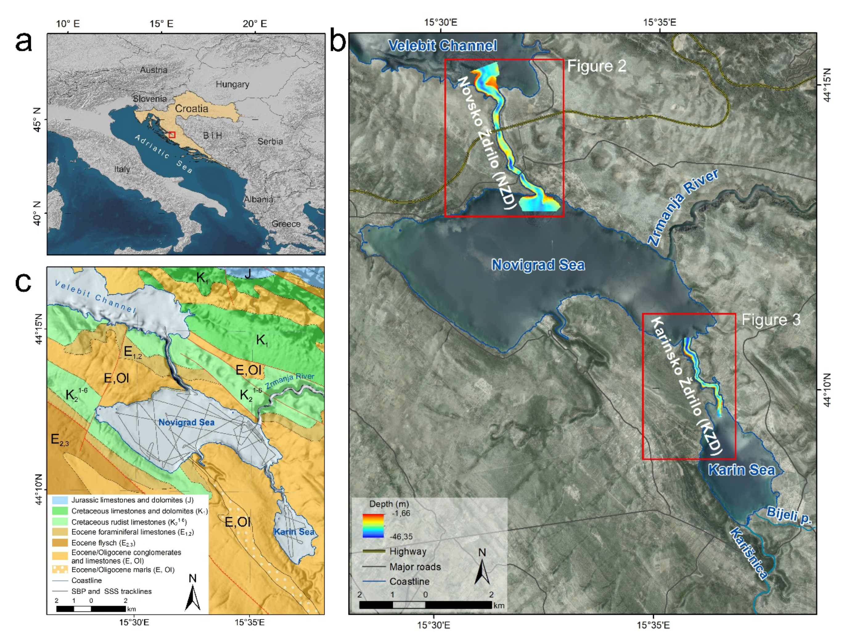
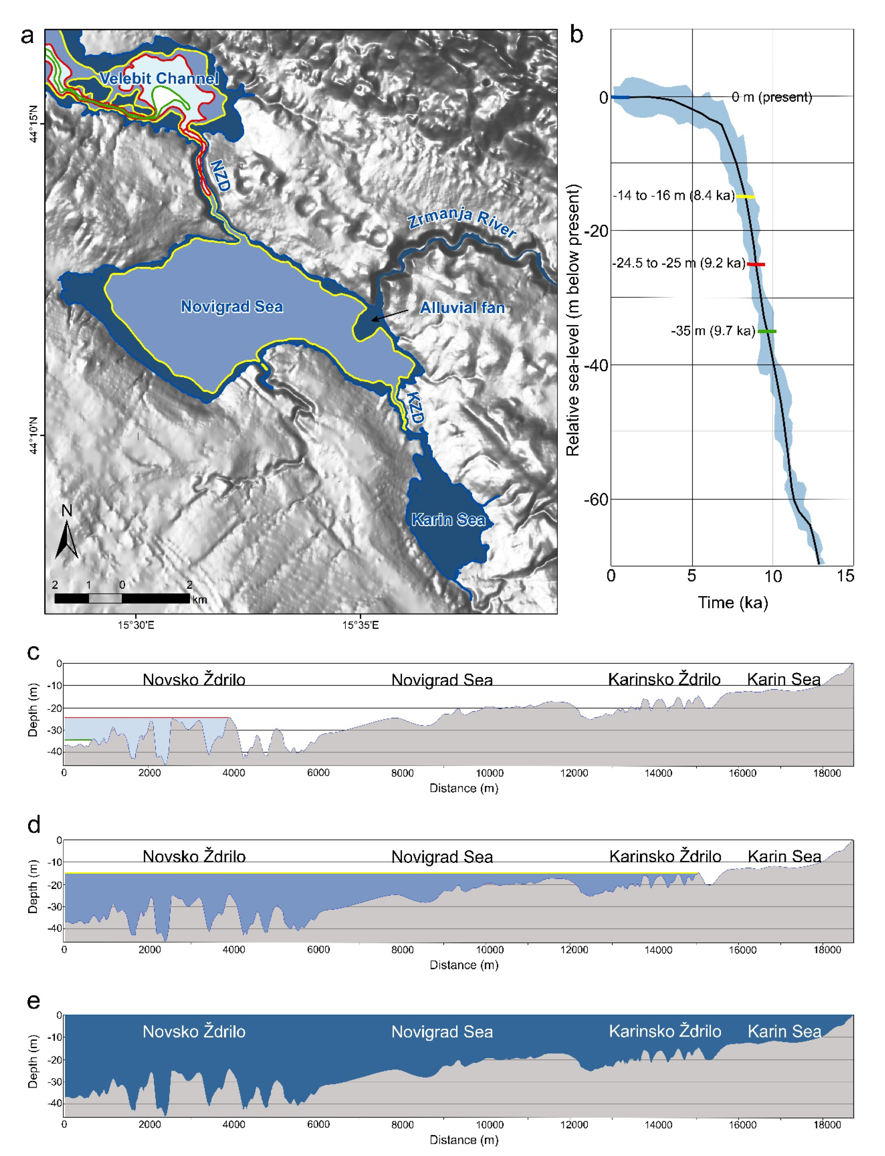
The Novigrad and Karin Seas are two small semi-enclosed marine bays located in northern Dalmatia on the eastern Adriatic coast, Croatia (
Figure 1a). The bays are interconnected via a submerged river canyon called Karinsko Ždrilo (KZD) (
Figure 1b). The Novigrad Sea is on the northern side, connected to Velebit Channel and open sea via another canyon-like passage called Novsko Ždrilo (NZD). The bays have a flat bottom with average depths of 26 to 30 m in the Novigrad Sea and 12 to 13 m in the Karin Sea [
27]. Both canyons are oriented in the NNW–SSE direction (
Figure 1b). Novsko Ždrilo is 3750 m long and 150 m to 250 m wide at sea level. Its steep slopes rise to 150 m above sea level (a.s.l.). The water depth within the NZD channel is 25 to 46 m. Karinsko Ždrilo has a less dramatic morphology with slopes rising 20 to 40 m a.s.l., whereas the canyon width is 115 m to 250 m at sea level. The water depth in KZD ranges from 15 to 25 m. Due to the region’s geographic importance in the connection of the interior with northern Dalmatia, two bridges cross NZD. The larger highway bridge is located at the central part of NZD, while the smaller local Maslenica Bridge is at the southern end of the channel (
Figure 1b).
Freshwater enters the Karin Sea via several periodical torrential rivers, but mainly through Karišnica and Bijeli Potok. The karst river Zrmanja, with a total length of 69 km, feeds the Novigrad Sea through a river canyon. It forms an estuary, which extends from Novsko Ždrilo up to 14 km inland until it reaches the tufa waterfall Jankovića Buk [
28]. The estuary is highly stratified most of the year [
29,
30]. The river is characterized by many tufa barriers that were formed as autogenous calcite deposits on macrophytes and microphytes [
31]. Tufa barriers across the Zrmanja River were previously studied from biological, geochemical, fossil evolution, and chronological points of view [
21,
31,
32,
33]. Tufa growth forms barriers, barrages, or waterfalls across the river valley. When carbonate-rich water falls vertically, vertical cascade tufas result. If water flows over steep slopes, the tufa occurs in the shape of fans, cones, or mounds [
19,
23,
32]. Often, tufa barrier growth forms dams and lakes. Some barriers in the Zrmanja River are still active and some are fossilized. Available studies from the Dinaric karst and the Zrmanja River show that the majority of them are of the Holocene age, with the most intensive growth in the last 7000 years [
31,
33,
34]. The existence of tufa barriers within Novsko Ždrilo has already been confirmed by scientist divers [
18], who claimed barrier heights of 10–20 m. The river’s complex karst hydrological characteristics are well described by Bonacci [
35]. Despite the numerous monitoring measurements, it was not possible to determine the exact karst aquifer (catchment) extent, but it is suggested that the Zrmanja River is connected with the neighboring Krka River through complex karst underground flows [
35]. There are also several periodical rivers feeding the Novigrad Sea from the west and south. The composition of sedimentary records has been analyzed from a geochemical perspective on short cores from the Novigrad Sea and Zrmanja River in order to determine the distribution of trace elements and differentiate the anthropogenic impacts from the natural background values [
36,
37,
38].
As a result of their isolated geomorphological location, sea currents and waves have a slight influence on the bays [
39]. Conversely, the Zrmanja River brings 2–3 times more freshwater annually than the total volume of the Novigrad Sea [
36]. Together with the freshwater flowing into the Karin Sea by Karišnica and Bijeli Potok, this amount of water can cause strong outflow currents in narrow channels, such as NZD and KZD.
The study area is a part of the Croatian karst Dinarides and consists of a thick carbonate succession deposited from the Late Palaeozoic to the Eocene. During the period from the Mesozoic to the Cenozoic, the area was a part of the large Adriatic–Dinaric Carbonate Platform (ADCP, [
40,
41]). The disintegration of the ADCP started in the Late Cretaceous and is characterized by the development of flysch basins and carbonate deposition on the margins. The transition from the Cretaceous to the Paleogene was marked by the regional emergence of the entire platform, followed by dynamic tectonics in the Paleogene. The final uplift of the entire Dinaric area culminated in the Oligocene and the Miocene as a result of the collision of Adriatic and Dinaric segments of the Platform [
40,
41]. The geological background of the studied area consists mainly of Mesozoic, Paleogene, and Neogene carbonates and clastic deposits [
42,
43,
44,
45,
46] (
Figure 1c), with
terra rossa soils and cambisols on limestone as the dominant soil types. The Mesozoic comprises Jurassic limestones and dolomites at the base, with a succession of Cretaceous limestones, dolomites, and carbonate breccias. Eocene limestones; dolomites and flysch; Oligocene limestones, conglomerates, and marls transgressively overlie Mesozoic rocks [
42,
43,
44,
45,
46] (
Figure 1c). Occurrences and deposits of bauxites can be found in the study area and the wider region, as well as a disused bauxite processing factory in the city of Obrovac [
42,
47,
48]. Prior to the rapid Pleistocene−Holocene transgression, the present-day Novigrad and Karin Seas acted as karst poljes. They were subsequently submerged, creating a typical drowned karst landscape together with the drowned canyon of the Zrmanja River [
14].
3. Materials and Methods
To study the morphology of the submarine canyons, we used pinger profiles and shipborne multibeam bathymetric data collected during the two surveys conducted in 2015 and 2019. A 2015 campaign comprised SBP and SSS surveys. We used a 3.5 kHz pinger (ORE), GeoAcoustics Ltd. (Great Yarmouth, UK) GeoPulse Transmitter model 5430A, and a GeoAcoustics Ltd. (Great Yarmouth, UK) GeoPulse Reciever model 5210A. SBP data was logged using a Triton SB-Logger (v 7.3, Triton Imaging Inc., Capitola, CA, USA). The signal penetration was limited by the water depth and shallow limestone bedrock and never exceeded 23 ms. Assuming a sound velocity of 1500 m/s, the vertical signal penetration was up to 17 m. A towfish EG&G 272 TD TVG (EG&G Inc., Gaithersburg, MD, USA) was towed 3 m below the sea surface and SSS data were recorded with an EdgeTech 4100P Topside Processor unit (EdgeTech Inc., Escondido, CA, USA). The positioning was obtained usinga Hemisphere DGPS (Hemisphere GNSS, Inc., Scottsdale, AZ, USA). The equipment was mounted on a 6 m long vessel moving at an average speed of 3.5 knots. Afterward, the SBP data were exported in a SEG-Y format (Society of Exploration Geophysicists Exchange Tape Format) and further interpreted in the Geosuite Allworks software (version 2.6.7., Geo Marine Survey System, Rotterdam, Netherlands).
The second campaign dataset was taken in 2019 comprised MBES mapping of the canyons. For this purpose, we used a WASSP S3 MBES (Furuno ENL, Auckland, New Zealand), which is capable of recording multibeam and backscatter data. It was side-mounted on a vessel moving at an average speed of 3.5 knots. The used MBES system works at a typical frequency of 160 kHz with an effective beam width (angular coverage) of 120 degrees using 224 beams. The beam width is 4.4 × 3.2 (PS/FA) with a transmitting voltage response of 155 dB and a receiving voltage response of -194 dB. The vessel motion was corrected for with a WASSP Sensorbox (Furuno ENL, Auckland, New Zealand) inertial measuring unit (IMU), which makes corrections for the pitch, roll, and heave. The IMU worked in conjunction with the Hemisphere Vector V103 DGPS compass antenna (Hemisphere GNSS, Inc., Scottsdale, AZ, USA) used for positioning. The data were acquired with WASSP CDX software (version 3.9, Furuno ENL, Auckland, New Zealand). Cleaning, processing, and validation of the MBES data were performed with the hydrographic software BeamworX Autoclean (version 2020.1.1.0., BeamworX BV, Utrecht, Netherlands).
Morphometric Analyses
The final MBES bathymetry and MBES backscatter grids were exported from BeamworX as a 1 m pixel ASCII grid for further analysis in ArcGIS (version 10.2.1, ESRI inc., Redlands, CA, USA). To create a more meaningful base for the GIS analyses, we gridded together the MBES bathymetry data with the available onshore and bathymetry data digitized from topographic maps 1:25,000 [
27] as line and point data into a georeferenced digital terrain model (DTM) with a 1 m pixel size.
Following an extensive literature review [
1,
3,
5,
6,
12,
49], we calculated a range of secondary features to classify and interpret the collected MBES bathymetry, MBES backscatter, and SSS data. ArcGIS with the Spatial Analyst extension to do the DTM, shaded relief, and slope analyses. We used the joined DTM to do the shaded relief and slope analysis, while other morphometric analyses were applied only for the MBES bathymetry/MBES backscatter data. A multidirectional hillshade was created to highlight the morphological features of the terrain, including channels and the bottom morphology. A slope analysis, which is relevant in a geomorphological context linked to the acceleration of currents, the stability of sediments, and erosion [
6], was calculated using the standard ArcGIS algorithm proposed by [
50]. To describe the heterogeneity of the studied canyons, we used a vector ruggedness measure (VRM). It was calculated using a Benthic Terrain Modeler ArcGIS tool package (version 3.0) [
12]. The calculated values are dimensionless and range from 0 (no variation) to 1 (complete variation). Typical values are small (up to 0.4) in natural data [
12]. Variations in the range were better observed when calculated for the MBES bathymetry data resampled to a 10 m cell size.
Curvature (the second derivative of the bathymetric surface, or the first derivative of the slope) was calculated using the standard ArcGIS tools according to the method proposed by [
51]. The curvature can be calculated parallel to the slope (profile curvature), where it describes the acceleration or deceleration of the flow, or perpendicular to the slope (plan or planiform curvature), which describes the convergence or divergence of the flow. The planiform curvature can be useful when defining ridges, valleys, and slopes along the side of the features [
5]. While values close to 0 indicate that the surface is flat, moderate relief values vary from −0.5 to 0.5 and extreme relief values vary between −4 and 4 or more. Physically, the calculated attributes can affect the marine flow, internal waves, and current channeling [
12]. Variations in the curvature were also better observed when calculated for the MBES bathymetry data that was resampled to a 10 m cell size.
The morphometric analyses included a combination of the fill DTM, flow direction, and flow accumulation needed to determine the flowline in the channels. The flowline presents the lowest possible pathway for water flowing out of the poljes during the sea-level lowstand, and a pathway for the sea to enter the poljes during the sea-level rise. By applying this methodology, it is possible to determine a correct relative sea level, and consequently, the timing of the Novigrad and Karin Sea drownings.
We made several attempts to classify the backscatter data using ArcGIS tools Spatial analyst tools (version 10.2.1, ESRI inc., Redlands, CA, USA). The best results of the unsupervised backscatter acoustic classifications were achieved using the ML uISO, and SMS. In ML, the mean vector and the covariance matrix characterize each class. A statistical probability can be calculated for each class based on these two cell values. This leads to the determination of the membership of the cell to a specific class [
49]. The procedure is based on Bayes’ theory of joint probabilities, which accounts for marginal distributions of datasets and their respective internal correlations under the assumption of multivariate normality in N-dimensional Euclidean space [
52]. uISO provides a quantitative unsupervised clustering using the functionalities of the Iso Cluster and Maximum Likelihood Classification tools. SMS determines clusters in the MBES backscatter raster by grouping adjacent pixels with similar spectral characteristics. The mean shift algorithm is a non-parametric clustering method for image segmentation. After applying the function, all convergence points are found and clusters are built from them. All convergence points closer than the range defined in the spatial domain are grouped. The number of significant clusters present in the feature space is automatically determined by the number of significant modes detected [
53].
4. Results
The use of available high-resolution bathymetry data (bathymetry, seismic, and side-scan sonar data) incorporated with the already available topographic data enabled us to undertake spatial and morphometric analyses of the Novsko Ždrilo and Karinsko Ždrilo channels.
4.1. Bathymetry and Morphometric Analyses
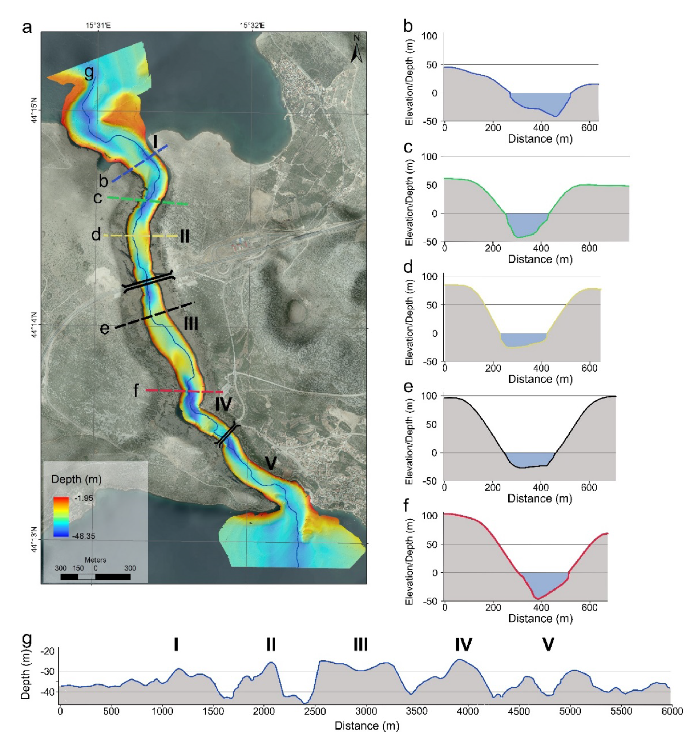
Both studied channels were characterized by elongated geometries and steep slopes (
Figure 1). The MBES bathymetry results showed a very distinct seabed within the channels, with multiple barriers, which is typical for a karst morphology (
Figure 2 and
Figure 3). This is well depicted in the profile lines (
Figure 2d and
Figure 3d), where multiple pronounced barriers are visible. The water depth at the northern entrance to Novsko Ždrilo was 39 m, whereas, on the SSE end of the channel, the water depth was 37 m. There was an S-shaped bend at the northern entrance to NZD, where the first barrier in NZD could be observed (marked as I in
Figure 2). After the bend toward the south, there was a deep part of the canyon with depths of over 40 m below sea level (b.s.l.) extending to the next barrier, which rose to 24.5 m b.s.l. in the lowest part (marked as II in
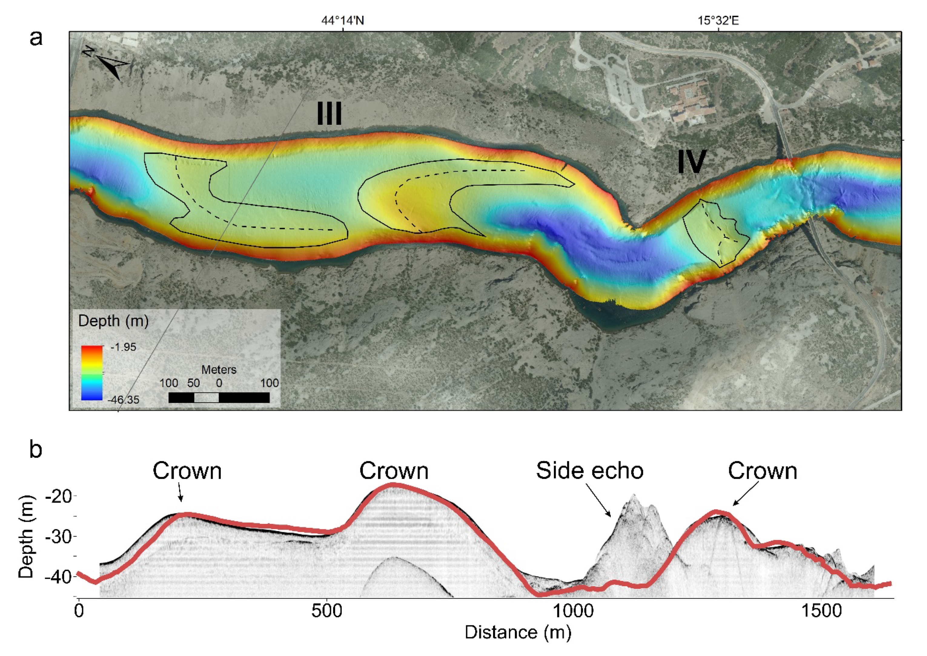
Figure 2a,d). The central part of the canyon was shallower, with two joining barriers at depths of 25–30 m b.s.l. in the lowest part of the crown (marked as III in
Figure 2a,d). To the south, this shallow part deepened steeply to the deepest part of the canyon below 45 m b.s.l., then rose steeply again to 26 m b.s.l. (marked as IV in
Figure 2). This was the most pronounced barrier as the channel deepened beyond this barrier toward the south, below 40 m b.s.l. The bottom elevated to form two minor barriers near the exit (marked as V in
Figure 2), then flattened toward the southern end.
The northern part of KZD was the deepest, with the depth at the northern end reaching 24 m b.s.l. (
Figure 3a,d). The bottom gradually elevated in the middle part of the KZD canyon, where the first barrier could be observed (marked as I in
Figure 3a,d). Altogether, there were four barriers at the southern part of the canyon (marked as I-IV in
Figure 2a,d), all with similar heights (14–16 m b.s.l.) and declining to similar depths (21–22 m b.s.l.). The depth at the southern end of the channel was also the deepest part of the Karin Sea, with a depth of 20.6 m b.s.l.
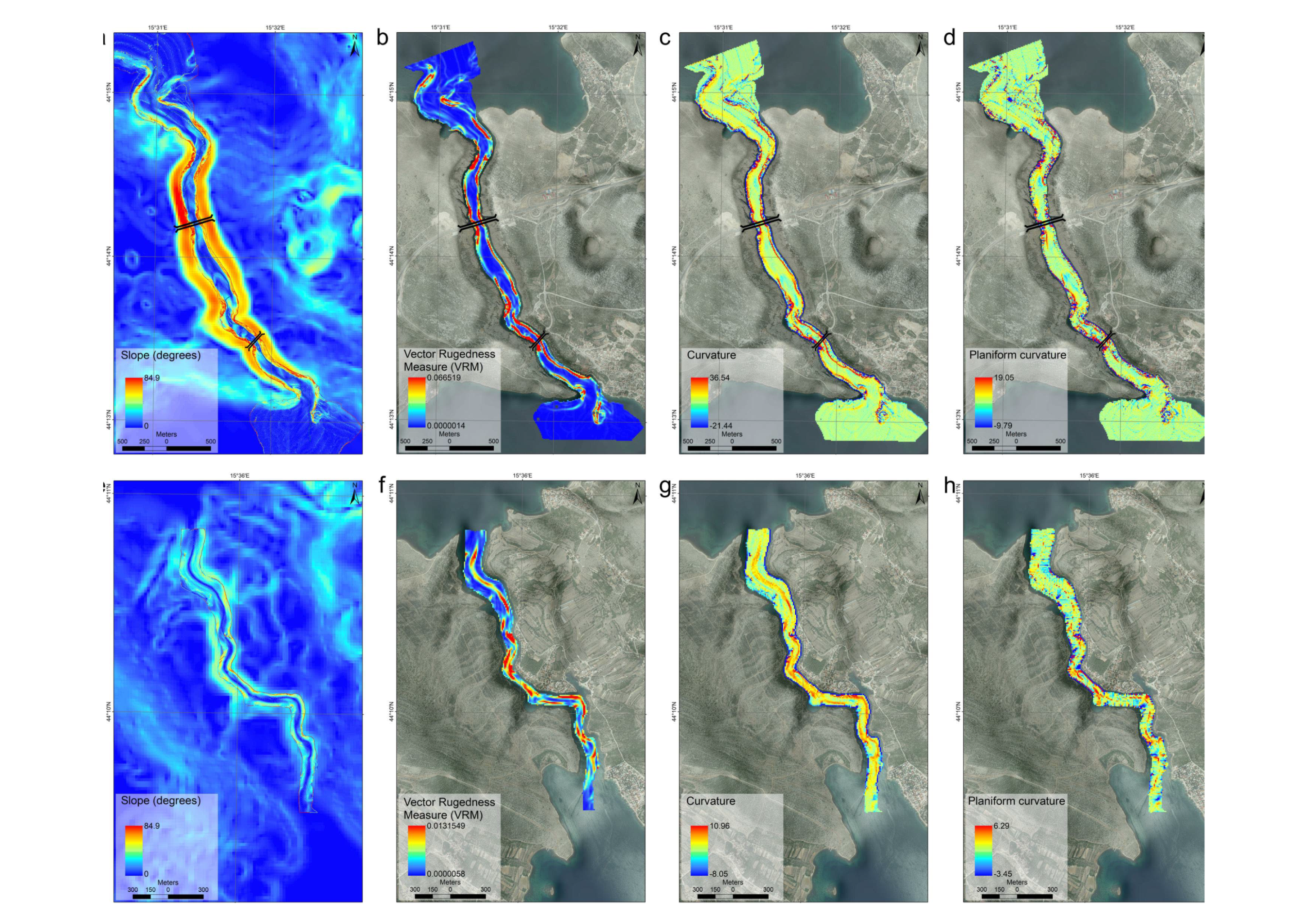
The slope analysis of the broader area surrounding the channels revealed what was already described: steep slopes rose to 150 m a.s.l. and the continuation of these slopes underwater, which reached almost to the bottom of the channels, where they flattened. The sidewalls in NZD had a maximum inclination of up to 44 degrees on the western side of the canyon close to barrier II (
Figure 2a and
Figure 4a). In the rest of the canyon, the slopes were still steep and inclined at 28–35°, flattening further at both channel ends.
The steepest slopes in KZD barely reached the inclinations observed with the NZD sidewalls, with a maximum inclination of 27 degrees, while the average inclinations were 15 to 20°. The steepest parts of the KZD were canyon slopes on both sides of the central-to-southern part of this channel (
Figure 4e).
We used the BTM VRM to present the surface roughness, where higher values should represent rockier surfaces (
Figure 4b,f). In the analysis of the generalized MBES bathymetry data with a 10 m cell size, the higher surface roughness was clearly visible on the sides in most of the NZD channel. In some areas in the southern and northern parts of the channel (red colours in
Figure 4b), high roughness areas extend throughout almost the whole width of the channel. The northern part of KZD, as well as the farthest southern flat-bottom parts of the KZD channel, exhibited low roughness values (
Figure 4f). The central part of the channel had high roughness values through its whole width (
Figure 4f).
Curvature analysis of the NZD 10 m MBES bathymetry data produced high values (blue and red colors,
Figure 4c) near the Maslenica bridge and 500 m to NW, under the highway bridge, and N toward the canyon exit. The curvature of the rest of the channel was low. The planiform curvature (which is meant to emphasize convex or concave forms in the relief) especially emphasized the area around the Maslenica bridge. The curvature analysis of the KZD exhibited elevated positive or negative values in the central and southern parts of the channel (
Figure 4g). The values in the central part were somewhat higher. The planiform curvature highlighted the central part of the channel as a part that had elevated values (
Figure 4h).
4.2. Acoustic Backscatter Characteristics and Its Derivatives
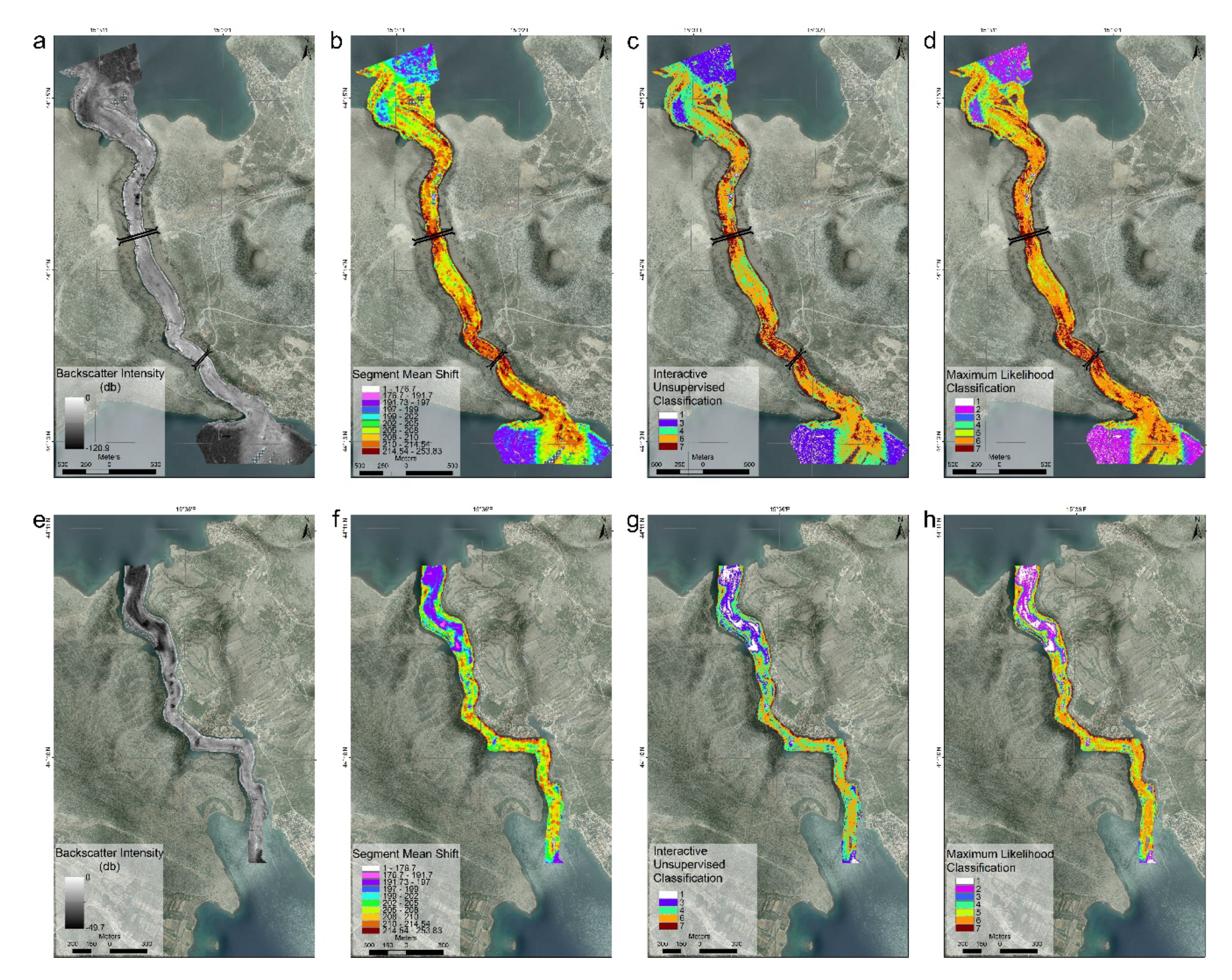
The backscatter intensity ranged from −10 db to −45 dB for 99.9% of the data in NZD, and from −16 dB to −38 dB in KZD (
Figure 5a,e). The backscatter physiography of the channels consisted of low acoustic backscatter surfaces at the canyon ends. Within the channels, the backscatter intensity increased, especially from the steep canyon sides.
A segmentation classification was created with 10 classes, out of which, 5 classes with values higher than 202 were relevant to NZD (
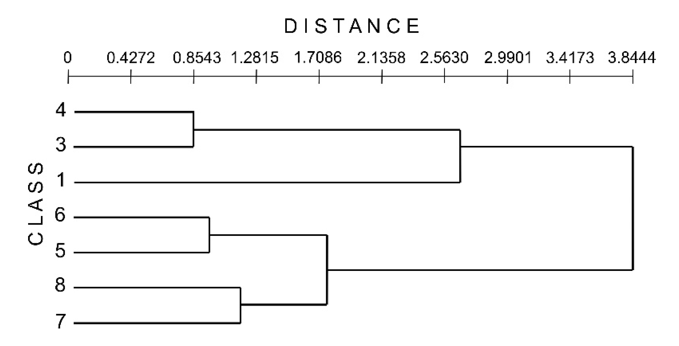
Figure 5b). The classification that was derived from the backscatter intensity in NZD resulted in diversification of the central part of the channel, while the NW and SE channel ends had lower values. Areas under the bridges had the highest values. Elevated values extended toward the north and south of the Maslenica bridge and north of the highway bridge. uISO created seven classes, where based on the created dendrogram, it was possible to further reduce the number of classes (
Figure 5c and
Figure 6). Classes with distances lower than 1 were merged, namely, classes 3 and 4 and classes 5 and 6, creating a classification with five classes (
Figure 5c and
Figure 6). The derived layer showed three classes within the channel, with a majority of the channel covered by class 6, while class 7 covered the areas near the bridges and north of them. Classes 3 and 4 were limited to the entrance/exit areas of the channel. A raster classification using ML derived seven classes. The classification showed that three classes were dominant within the channel. A majority of the channel was covered with class 7, while class 8 covered the areas near both bridges and north of them. Classes 3, 4, and 5 were limited to the entrance/exit areas of the channel. ML composed very similar visual results to uISO.
The segmentation classification for KZD created 10 classes. Classes with lower values (176–199) were dominant at both channel ends. At the NW end of KZD, classes with values 176–199 reached well within the channel, approximately 800 m from the NW end (
Figure 5). Going southward, classes with green and light-yellow colors dominated (values 199–210), while the highest values could be detected in the central part and on the eastern channel sides along most of the channel length. The uISO for KZD consisted of seven classes. A reduction to five classes based on the dendrogram (
Figure 6) produced a similar result. Classes 1, 2, and 3 were dominant at the channel ends, and were more pronounced in the NW area. Classes 6 and 7 dominated the rest of the channel. Class 8 appeared on the eastern steep sides of most of KZD and on the western sides of the central part of the channel. ML derived seven classes. The classification showed that classes 1 and 3 were dominant at the channel ends. At the NW end of KZD, classes 1 and 3 reached 800 m within the channel from the NW end. Classes 6 and 7 covered the rest of the channel, and class 8 covered the channel sides.
4.3. Side-Scan Sonar
A visual analysis of the SSS mosaic revealed several morphological characteristics that helped to interpret the MBES bathymetry, MBES backscatter, and SBP data.
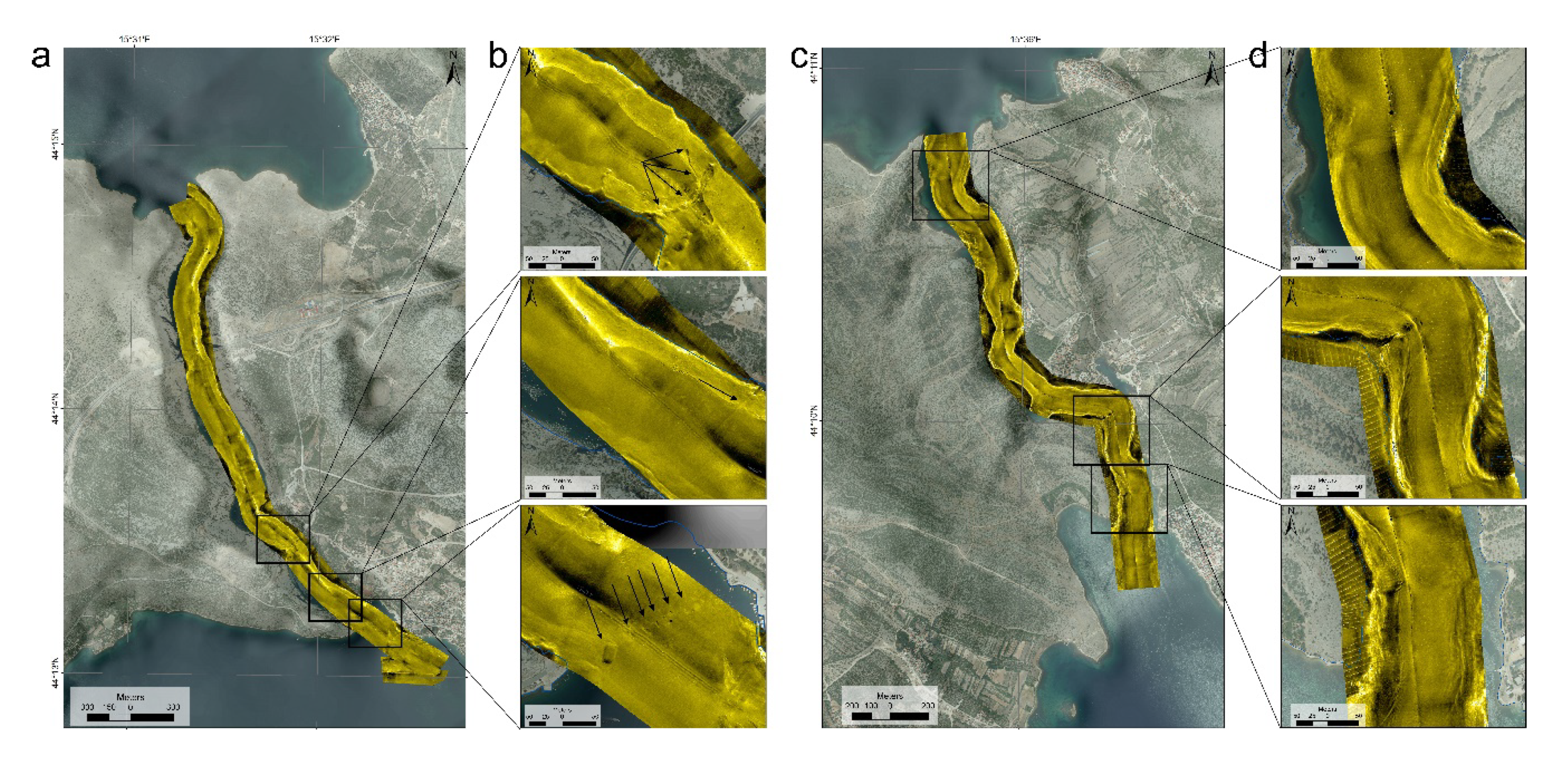
The central-bottom part of the NZD canyon entrance and the deeper central parts of the channel exhibited low reflectivity of the planar surface in the SSS mosaic. The sides of the channel showed high reflectivity throughout the whole length of the channel. The eastern steep sides appeared to have more exposed boulders and rocky outcrops on the slopes (
Figure 7). This was especially highlighted on the sharp bends within the canyon. There was a collapsed steel structure visible in the southern part of the canyon, spreading across the whole width of the channel (
Figure 7). This underwater construction was the remains of a bridge demolished during the War of Independence in 1991 [
54]. It is located below the present steel bridge that was constructed in 2005 [
54]. After the bridge demolition, a floating bridge was constructed at the southern entrance to the canyon. Its concrete supports were still well visible on the SSS mosaic image (
Figure 7b). The shallows at the southern end of the SSS mosaic had rocky outcrops and were partially covered with sediments with visible waveforms (
Figure 7b).
Similar to NZD, KZD had a flat bottom-central part of the channel with a lower reflectivity on the SSS mosaic, while steep sides exhibited a higher reflectivity (
Figure 7). A low reflectivity was the most pronounced at the northern part of the canyon entrance (for approximately 800 m southward). Rocky outcrops and solitary boulders were exposed, especially on the steep sides of the sharp bends (
Figure 7d).
The effort to classify the SSS mosaic using ArcGIS tools failed to provide useful results, creating only a small number of classes.
4.4. Sub-Bottom Profiler
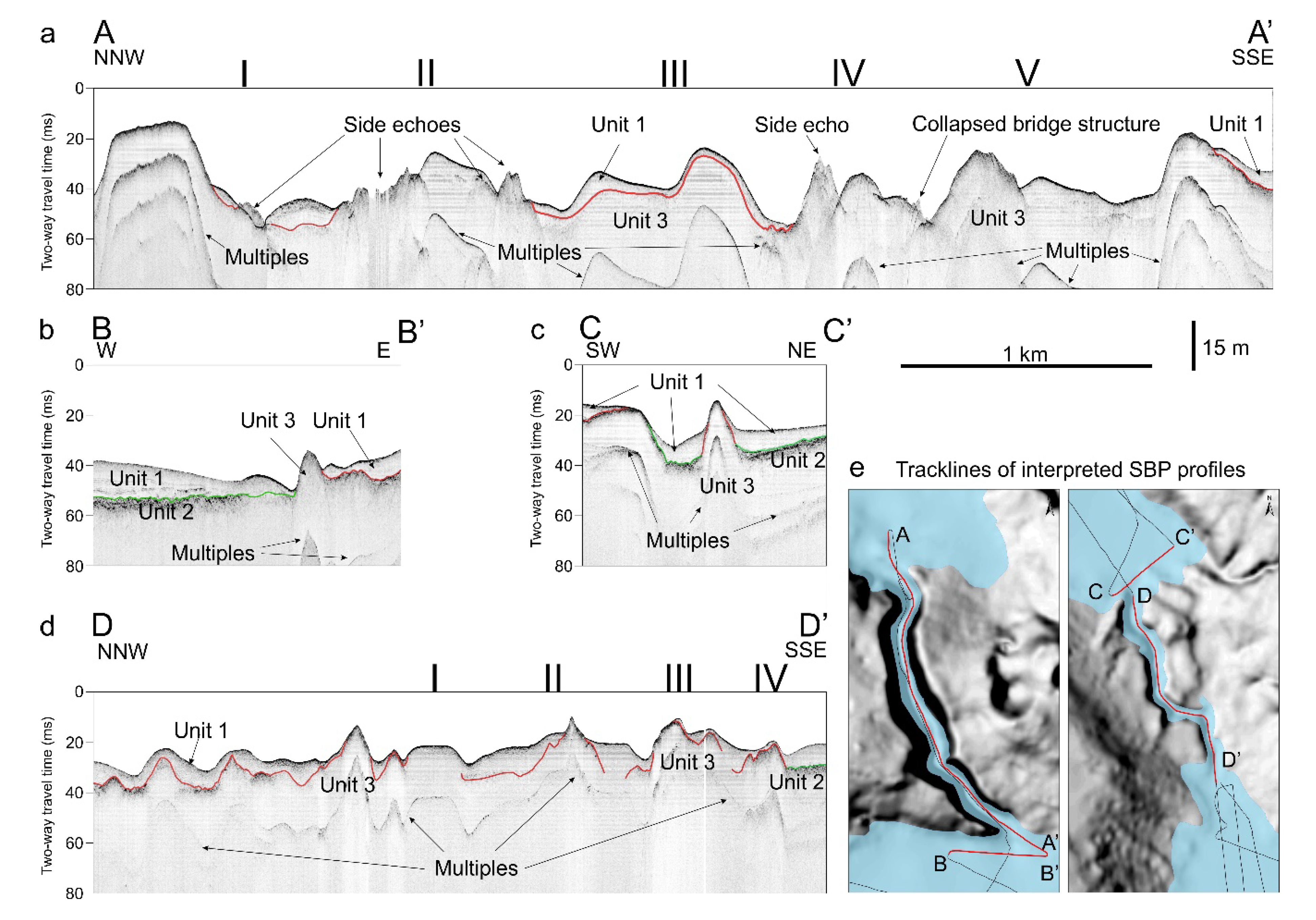
The penetration of the SBP seismic signal was limited due to a very thin sediment cover over the limestone bedrock and shallow water depth causing the occurrence of multiples. Three acoustic units could be determined at the SE end of NZD on the profile perpendicular to the channel (
Figure 8b). The uppermost seismic unit (unit 1,
Figure 8) was acoustically semi-transparent. Some internal parallel reflectors with weak amplitudes were visible at the base of this unit. The lower sediment unit (unit 2) was characterized by high acoustic amplitudes. The acoustic signal penetrated for less than 10 ms through this unit, indicating coarse sediments. Units 1 and 2 were separated by a high amplitude unconformity with an irregular surface. The acoustic basement (unit 3) was interpreted as bedrock. Due to its relative position in the stratigraphic succession and surrounding surface geology, it is safe to presume that it was bedrock constituted of karstified limestones. The acoustic profile through NZD showed a very dynamic morphology of the upper surface with many barriers in the form of ridges, where some were covered with sediment. Side-echo refractions, caused by the steep adjacent barriers, were observed throughout the profile. A thin overlay of acoustically semi-transparent sediments was visible in the central to northern part of the profile (
Figure 8a). It was separated from the bedrock by a very weak amplitude reflector. Due to the water depth, multiples could also be observed throughout the whole SBP profile.
The same three acoustic units could be determined at the SE end of KZD on the profile perpendicular to the KZD channel (
Figure 8c). The uppermost unit was acoustically semi-transparent (unit 1) with some weak reflectors on the bottom of the unit. The underlying unit 2 had high acoustic amplitudes and attenuated the signal penetration. Unit 3 exhibited sharp and steep ridges in the middle of the profile and along the base of the western side of the profile, which were draped by units 1 and 2.
An SBP profile along KZD indicated a very dynamic bathymetry. Several steep carbonate ridges (unit 3) penetrated through the sediment cover to the seabed surface (
Figure 8d). Most of the bedrock was covered with the acoustically semi-transparent sediments of unit 1. On the NW third of the profile, the bedrock was draped with the thicker sediment succession of unit 2. Southward, several carbonate ridges pointed out to the surface, while the space in between was partially filled with acoustically semi-transparent sediments. A thicker unit 2 succession was determined at the SE end of KZD.
5. Discussion
Integration of the acoustic and morpho-bathymetric surveys enabled us to reconstruct a detailed bottom morphology of the two narrow karst canyons that connect two semi-enclosed bays, the Novigrad and Karin Seas. Merging the available high-resolution hydroacoustic data-bathymetric, high-resolution seismic, and side-scan sonar data with the already available topographic data enabled us to make spatial and morphometric analyses and create maps to describe the unique environment that acted as a river discharge passage during the sea lowstand, as well as an inlet of the sea into the basins and estuary. Steep slopes and a pronounced bottom morphology characterized the canyons.
5.1. Morphology of the Canyons
Analysis of the MBES bathymetry measurements in NZD revealed six barriers extending along the channels to their steep sides. The steepness of the channel sides was highlighted in the slope and curvature analyses that provided typical values for extreme relief [
55]. Three barriers rose to a depth of 25 m b.s.l., with a height difference of 15–20 m, extending to a maximum depth of 45 m b.s.l. The bottom morphology of NZD was very irregular, as depicted on the bathymetric profile and as highlighted by many side-echo refractions visible on the SBP profile (
Figure 8a). Adjacent steep rocky outcrops or steep sidewalls cause side-echo refractions [
13]. The sediment thickness was higher in the bays, as evidenced by the SBP profile perpendicular to the NZD channel. Within the channel, the sediment overlay was thin or non-existent on the most barriers, and a significant sediment build-up was only noticed on barriers 2 and 3 in the central part of the channel. Thin sediment cover was emphasized by the increased surface roughness of the steep channel sides, depressions, and some barriers (
Figure 4). This lack of sediment cover was most likely caused by strong present-day currents in the narrow channels. Strong sea-bottom currents can be caused by a significant input of freshwater into two bays, as the Zrmanja River alone brings 2–3 times more water annually than the total volume of the Novigrad Sea [
37]. To this volume, we must add the contribution of the rivers Karišnica and Bijeli Potok flowing into the Karin Sea, as well as karst underground flows ending as submarine springs in the Novigrad Sea [
35]. Tidal currents have a negligible effect on the estuary, as tides are rather weak, with M2 amplitudes below 10 cm [
28]. As the MBES backscatter signal differs due to the bottom type and its physical characteristics, namely, its hardness or softness [
1,
8]. Thus, it was possible to classify the MBES backscatter data. A thicker sediment succession at the ends of the NZD channel, which was visible on the SBP profiles, was well delineated in the MBES backscatter derivatives (
Figure 5) due to different characteristics compared to sediments within the channel. Within the NZD channel, the MBES backscatter intensity increased, pointing to a rockier surface with a high acoustic backscatter. Sediments in the deepest areas or depressions were also well defined as a class with different sediment characteristics.
The bathymetry data for KZD showed the deeper and more even bottom of the northern part, while the southern half of the channel revealed five barriers. The barriers were equally deep and had similar heights rising to a depth of 14–16 m b.s.l. The SBP data pointed to the fact that most of the channel was covered with at least several meters of sediment, with only peaks of the barriers in the southern part of the KZD comprising a thin sediment overlay (
Figure 8). The northern part of the channel bedrock was covered with a thicker sediment succession that increased toward the Novigrad Sea. Higher surface roughness in the central part of KZD, as well as toward the southern part, highlighted the more uneven morphology of the southern part of the channel. The diversification in the MBES backscatter signal derivatives due to the difference in the physical characteristics of the sediment [
1,
8] was most pronounced in the northern part of KZD, where a thicker sediment succession was visible on the seismic profiles. Similar characteristics could be observed on the southern end of the channel.
Despite the similarity in their appearance, it seems as if the KZD was a “reduced” version of NZD in many ways. The steep sides of NZD rose 150 m a.s.l., with depths below 40 m, while the KZD slopes rose to 40 m a.s.l. and the channel was only up to 20 m deep. The pattern was similar in the case of the bottom morphology, which was more prominent in NZD. One of the reasons for the milder morphology was the thicker sediment cover in KZD. There were several reasons for the preservation of the thicker succession of sediments within KZD: the currents were not as strong as in NZD due to the reduced freshwater influx that only came from the short periodical rivers Karišnica and Bijeli Potok, which is in contrast to NZD, where the volume of the freshwater influx was significantly higher as a result of rivers flowing into the Karin and Novigrad Seas, including the Zrmanja River [
37]. Another reason can be found in the easily erodible flysch sediments abundant in the Karišnica and Bijeli Potok watersheds [
45] (
Figure 1c).
It is clear that the majority of submerged barriers within the canyons were karstic limestone forms. What is still unclear is whether all the submerged barriers in the canyons are made of tufa. The reason for the assumption of tufa barriers in the canyon is the existence of many relicts and recent tufa barriers in the Zrmanja River [
21,
31,
32,
33]. Therefore, favorable conditions for tufa growth in the studied canyons also existed during the lowstand. Ultimately, the morphology of tufa deposits is controlled by the topography and water flow regime [
32]. The growth and calcification of rheophilic algae and mosses produce porous hardened substrates and results in a lateral displacement that extends across the river, forming dams with lakes behind them [
22]. The tufas in Zrmanja River are described as waterfall and barrage tufas, with some waterfalls being more than 8 m high [
21,
32]. Tufa barriers higher than 10 m have been detected in the NZD by scientist divers, with one barrier reaching 20 m high with a crest at a depth of 26 m b.s.l. [
18]. Five barriers could be detected in the presented data with crests at the highest depths of 16–30 m b.s.l. in NZD, and four barriers with crowns at the highest depths of 14–16 m b.s.l. in KZD (
Figure 9; see also
Figure 2,
Figure 3 and
Figure 8).
The SSS mosaic proved to be very useful for determining rocky areas, as well as single boulders collapsed from the steep canyon sides. The anthropogenic effect on the NZD bottom was best recorded on the SSS mosaic, documenting the remains of a collapsed metal bridge construction, which comes from past war efforts during the 1990s War of Independence [
54]. The anthropogenic effect was also visible in the form of concrete blocks delineating the path of a temporary floating bridge that was constructed at the southern entrance of the NZD due to the collapse of the pre-1990 bridge [
54].
5.2. The Role of the Channels and the Barriers in the Holocene Flooding of the Novigrad and Karin Seas
There are many definitions of an estuary, where many include not only its present state under the influence of the river and the sea but also its morphogenetic origin [
56,
57]. In this way, Dalrymple et al. [
58] define an estuary as “the seaward portion of a drowned river valley system which receives sediment from both fluvial and marine sources and which contains facies influenced by tide, wave and fluvial processes.” Evans and Prego [
56] conclude that estuaries were produced by a relative rise in sea level and drowning of a previous erosional depression produced via fluvial erosion. Due to the rapid late Pleistocene–Holocene transgression, the river canyons and the poljes in the present-day Novigrad and Karin Seas were submerged [
14]. Based on the data gathered in this study and the available data on the relative sea-level rise, we can make hypotheses regarding the evolution of the lower part of the Zrmanja River estuary during the Holocene sea-level rise (
Figure 10). During that period the sea level rose 65 m [
15,
16,
59], and eventually formed today’s Zrmanja River estuary along with the Novigrad and Karin Seas. The tufa barriers presented a significant factor for the flooding of poljes, as they created 10-20 m high barrages that prevented water from flowing directly (
Figure 10). The similarity with the present Zrmanja River is evident, whose present estuary ends at Jankovića Buk, a tufa waterfall that creates a border between an estuary and a river [
30,
35]. The present river flow is intermittent with plenty of active and fossil tufa barriers [
1,
31]. The created flowline, as the lowest possible water path in NZD and KZD, allowed us to determine the pathway through the canyon and the relative sea level during the flooding of the Novigrad and Karin Seas. The sea level reached the lowest part of the crest of the barriers in NZD at the present depth of −24.5 to −25 m, and afterward, flooded the Novigrad Sea (
Figure 10a–c). Flooding of the polje in the Novigrad Sea area enabled the formation of the Zrmanja River underwater fan, as the sea-level rise caused the deposition of river sediment at the exit of the canyon (
Figure 10a). When the sea level rose to the depths of −14 m to −16 m, it reached the crest of the barriers in KZD (
Figure 10a,b,d). As the sea level continued to rise, it flooded the Karin Sea until it reached the present level (
Figure 10a,b,d). Based on the relative sea-level curve [
16] and the heights of the barriers, the estimated time of the flooding of NZD, and consequently Novigrad Sea, was after 9200 BP, while the time of the flooding of KZD, and consequently Karin Sea, can be estimated as having occurred after 8400 BP (
Figure 10b).
Further investigations of the sediments deposited in these basins (including sediment cores and high-resolution acoustic methods) will provide more conclusive answers about the timing of the Holocene sea-level rise.
6. Conclusions
High−resolution MBES bathymetry, MBES backscatter, SBP, and SSS measurements were carried out in two canyons to provide the first insights into the contemporary physiography of this unique environment consisting of two semi-isolated basins (the Novigrad and Karin Seas) connected with narrow steep channels Novsko Ždrilo and Karinsko Ždrilo.
NZD connects the Novigrad Sea with the open sea. It is also a part of the 15-km-long estuary of the Zrmanja River flowing into the Novigrad Sea and brings large volumes of freshwater. NZD canyon comprised steep and high side slopes extending up to 150 m a.s.l. Six barriers were detected within NZD, extending from the top of the barriers at −25 m b.s.l. to the bottom at −45 m b.s.l. The barriers were most probably all made of tufa, as detected by divers and as an analog with past and present tufa growth in the Zrmanja River. Those barriers prevented marine flooding during the Holocene sea−level rise since during the lowstand, the semi−isolated Novigrad and Karin Seas acted as karst poljes. Strong outflow currents prevented significant sediment build-up. A thicker sediment succession was detected at the ends of the channel extending to the open sea and bay. This was well depicted in SBP profiles and delineated in the MBES backscatter intensity and its derivatives. KZD connects the Karin Sea with the Novigrad Sea. The KZD canyon characteristics were less prominent compared to NZD, with lower and less steep sides. The five barriers detected in KZD were mainly covered in sediment and extended from 14 to 16 m b.s.l.
The post-LGM sea-level rise drowned the coastal karstic landscapes in the Eastern Adriatic Coast, including the Zrmanja River canyon and two poljes, the present-day Novigrad and Karin Seas. Determination of the lowest possible water path in NZD and KZD allowed us to determine the elevation of the relative sea-level rise. The sea level reached the top of the barriers in NZD at a present depth of −24.5 m to −25 m, and in KZD from −14 m to −16 m. The timing of the flooding of the channels and the bays was estimated based on the relative sea−level curve for the Adriatic Sea after 9200 BP in NZD and after 8400 BP in KZD.
SSS proved useful for determining the anthropogenic effect on the NZD bottom, where the remains of metal construction of the collapsed bridge, as well as concrete supports of the floating bridge, were detected.
Knowledge of the geomorphology of the aforementioned karst features is the most important for the relative sea-level reconstruction. When merged with additional investigations of the sediments deposited in the studied basins, which include sediment cores and high-resolution acoustic methods, these results will provide new insights into the timing of the rapid Holocene relative sea-level rise in the eastern Adriatic coast, as well as in other Mediterranean coastal areas [
60].
Author Contributions
Conceptualization, O.H. and S.M.; methodology, O.H., S.M. and D.B.; software, O.H.; validation, O.H., S.M. and D.B.; formal analysis, O.H.; investigation, O.H., S.M., G.P., D.C., M.G., D.B. and N.I.; resources, S.M.; writing—original draft preparation, O.H., S.M. and D.B.; writing—review and editing, O.H., D.B., S.M., N.I., G.P., D.C. and M.G.; visualization, O.H., S.M. and D.B.; supervision, S.M.; project administration, S.M. and N.I.; funding acquisition, S.M., O.H. and N.I. All authors have read and agreed to the published version of the manuscript.
Funding
This research was funded by the Croatian Science Foundation (HRZZ) under the project “Lost Lake Landscapes of the Eastern Adriatic Shelf” (LoLADRIA), grant number HRZZ-IP-2013- 11-9419, and the EMODNet Geology project, grant number EASME/EMFF/2018/1.3.1.8/Lot1/SI2.811048.
Acknowledgments
The authors would like to thank Nikos Georgiou, Xenophon Dimas, George Ferentinos, and Margarita Iatrou from the University of Patras for their support during the seismic survey and during the interpretation of the seismic data. The authors would like to acknowledge the anonymous reviewers and editors for their valuable comments, which helped to improve the quality of this manuscript.
Conflicts of Interest
The authors declare no conflict of interest. The funders had no role in the design of the study; in the collection, analyses, or interpretation of data; in the writing of the manuscript, or in the decision to publish the results.
References
- Bellec, V.K.; Bøe, R.; Rise, L.; Lepland, A.; Thorsnes, T.; Rún Bjarnadóttir, L. Seabed sediments (grain size) of Nordland VI, offshore north Norway. J. Maps 2017, 13, 608–620. [Google Scholar] [CrossRef] [Green Version]
- Buhl-Mortensen, L.; Buhl-Mortensen, P.; Dolan, M.F.J.; Holte, B. The MAREANO programme—A full coverage mapping of the Norwegian off-shore benthic environment and fauna. J. Mar. Res. 2015, 1, 4–17. [Google Scholar] [CrossRef]
- Deiana, G.; Holon, F.; Meleddu, A.; Navone, A.; Orrù, P.E.; Paliaga, E.M. Geomorphology of the continental shelf of Tavolara Island (Marine Protected Area ‘Tavolara-Punta Coda Cavallo’—Sardinia NE). J. Maps 2019, 15, 19–27. [Google Scholar] [CrossRef] [Green Version]
- Amiri-Simkooei, A.R.; Snellen, M.; Simons, D.G. Riverbed sediment classification using multi-beam echo-sounder backscatter data. J. Acoust. Soc. Am. 2009, 126, 1724–1738. [Google Scholar] [CrossRef]
- Wilson, F.J.; O’Connell, B.; Brown, C.; Guinan, J.C.; Grehan, A.J. Multiscale Terrain Analysis of Multibeam Bathymetry Data for Habitat Mapping on the Continental Slope. Mar. Geod. 2007, 30, 3–35. [Google Scholar] [CrossRef] [Green Version]
- Dolan, M.F.J. Calculation of Slope Angle from Bathymetry Data Using GIS—Effects of Computation Algorithms, Data Resolution and Analysis Scale; NGU-Report 2012.041; Geological Survey of Norway: Trondheim, Norway, 2012; p. 44. [Google Scholar]
- Che Hasan, R.; Ierodiaconou, D.; Laurenson, L.; Schimel, A. Integrating Multibeam Backscatter Angular Response, Mosaic and Bathymetry Data for Benthic Habitat Mapping. PLoS ONE 2014, 9, e97339. [Google Scholar] [CrossRef] [Green Version]
- Lurton, X.; Lamarche, G. (Eds.) Backscatter Measurements by Seafloor-Mapping Sonars; Guidelines and Recommendations; GeoHab Group: Venice, Italy, 2015; p. 192. [Google Scholar]
- Dartnell, P.; Gardner, J.V. Predicting seafloor facies from multibeam bathymetry and backscatter data. Photogramm. Eng. Remote Sens. 2004, 9, 1081–1091. [Google Scholar] [CrossRef] [Green Version]
- Erdey-Heydorn, M.D. An ArcGIS Seabed Characterization Toolbox Developed for Investigating Benthic Habitats. Mar. Geod. 2008, 31, 318–358. [Google Scholar] [CrossRef]
- Le Bas, T. RSOBIA—A new OBIA Toolbar and Toolbox in ArcMap 10.x for Segmentation and Classification. Photogramm. Eng. Remote Sens. 2016, 70, 1081–1091. [Google Scholar] [CrossRef]
- Walbridge, S.; Slocum, N.; Pobuda, M.; Wright, D.J. Unified Geomorphological Analysis Workflows with Benthic Terrain Modeler. Geosciences 2018, 8, 94. [Google Scholar] [CrossRef] [Green Version]
- Trottier, A.-P.; Lajeunesse, P.; Gagnon-Poiré, A.; Francus, P. Morphological signatures of deglaciation and postglacial sedimentary processes in a deep fjord lake (Grand Lake, Labrador). Earth Surf. Process. Landf. 2020, 45, 928–947. [Google Scholar] [CrossRef]
- Pikelj, K.; Juračić, M. Eastern Adriatic Coast (EAC): Geomorphology and Coastal Vulnerability of a Karstic Coast. J. Coast. Res. 2013, 29, 4. [Google Scholar] [CrossRef]
- Correggiari, A.; Roveri, M.; Trincardi, F. Late Pleistocene and Holocene Evolution of the North Adriatic Sea. II Quat. 1996, 9, 697–704. [Google Scholar]
- Lambeck, K.; Antonioli, F.; Anzidei, M.; Ferranti, L.; Leoni, G.; Scicchitano, G.; Silenzi, S. Sea level change along the Italian coast during the Holocene and projections for the future. Quat. Int. 2011, 232, 250–257. [Google Scholar] [CrossRef]
- Benjamin, J.; Rovere, A.; Fontana, A.; Furlani, S.; Vacchi, M.; Inglis, R.H.; Galili, E.; Antonioli, F.; Sivan, D.; Miko, S.; et al. Late Quaternary sea-level changes and early human societies in the central and eastern Mediterranean Basin: An interdisciplinary review. Quat. Int. 2017, 449, 29–57. [Google Scholar] [CrossRef] [Green Version]
- Bakran-Petricioli, T.; Petricioli, D. Habitats in Submerged Karst of Eastern Adriatic Coast—Croatian Natural Heritage. Croat. Med. J. 2008, 49, 455–458. [Google Scholar] [CrossRef] [PubMed] [Green Version]
- Viles, H.A.; Goudie, A.S. Tufas, travertines and allied carbonate deposits. Prog. Phys. Geogr. Earth Environ. 1990, 14, 19–41. [Google Scholar] [CrossRef]
- Primc-Habdija, B.; Habdija, I.; Plenković-Moraj, A. Tufa deposition and periphyton overgrowth as factors affecting the ciliate community on travertine barriers in different current velocity conditions. Hydrobiologia 2001, 457, 87–96. [Google Scholar] [CrossRef]
- Pavlović, G.; Prohić, E.; Miko, S.; Tibljaš, D. Geochemical and Petrographic Evidence of Meteoric Diagenesis in Tufa Deposits in Northern Dalmatia (Zrmanja and Krupa Rivers, Croatia). Facies 2002, 46, 27–34. [Google Scholar] [CrossRef]
- Golubić, S.; Violante, V.; Plenković-Moraj, A.; Grgasović, T. Travertines and calcareous tufa deposits: An insight into diagenesis. Geol. Croat. 2008, 61, 363–378. [Google Scholar] [CrossRef]
- Peña, J.L.; Sancho, C.; Lozano, M.V. Climatic and tectonic significance of late Pleistocene and Holocene tufa deposits in the Mijares river canyon, eastern Iberian Range, northeast Spain. Earth Surfa. Proc. Land. 2000, 25, 1403–1417. [Google Scholar] [CrossRef]
- Ferentinos, G.; Papatheodorou, G.; Geraga, M.; Iatrou, M.; Fakiris, E.; Christodoulou, D.; Dimitriou, E.; Koutsikopoulos, C. Fjord water circulation patterns and dysoxic/anoxic conditions in a Mediterranean semi-enclosed embayment in the Amvrakikos Gulf, Greece. Estuar. Coast. Shelf Sci. 2010, 88, 473–481. [Google Scholar] [CrossRef]
- Cukur, D.; Krastel, S.; Çağatay, M.N.; Damcı, E.; Meydan, A.F.; Kim, S.P. Evidence of extensive carbonate mounds and sublacustrine channels in shallow waters of Lake Van, eastern Turkey, based on high-resolution chirp subbottom profiler and multibeam echosounder data. Geo-Mar. Lett. 2015, 35, 329–340. [Google Scholar] [CrossRef]
- Manoutsoglou, E.; Hasiotis, T.; Kyriakoudi, D.; Velegrakis, A.; Lowag, J. Puzzling micro-relief (mounds) of a soft-bottomed, semi-enclosed shallow marine environment. Geo-Mar. Lett. 2018, 38, 359–370. [Google Scholar] [CrossRef]
- Topographic Map scale 1:25000 (TK25); Državna Geodetska Uprava: Zagreb, Croatia, 2010.
- Viličić, D.; Terzić, S.; Ahel, M.; Burić, Z.; Jasprica, N.; Carić, M.; Caput Mihalić, K.; Olujić, G. Phytoplankton abundance and pigment biomarkers in the oligotrophic, eastern Adriatic estuary. Environ. Monit. Assess 2008, 142, 199–218. [Google Scholar] [CrossRef] [PubMed]
- Burić, Z.; Cetinić, I.; Viličić, D.; Caput Mihalić, K.; Carić, M.; Olujić, G. Spatial and temporal distribution of phytoplankton in a highly stratified estuary (Zrmanja, Adriatic Sea). Mar. Ecol. 2007, 28, 169–177. [Google Scholar] [CrossRef]
- Viličić, D. Ecological characteristics of the Zrmanja estuary. Hrvat. Vode 2011, 19, 201–214. [Google Scholar]
- Horvatinčić, N.; Krajcar Bronić, I.; Obelić, B. Differences in the 14C age, δ13C and δ18O of Holocene tufa and speleothem in the Dinaric Karst. Palaeogeogr. Palaeocimatol. Palaeoecol. 2003, 193, 139–157. [Google Scholar] [CrossRef]
- Pedley, M. Tufas and travertines of the Mediterranean region: A testing ground for freshwater carbonate concepts and developments. Sedimentology 2009, 56, 221–246. [Google Scholar] [CrossRef]
- Veverec, I.; Faivre, S.; Barešić, J.; Buzjak, N.; Horvatinčić, N. Evolucija fosilne sedrene barijere Gazin kuk u rijeci Zrmanji (Hrvatska). In Zbornik Sažetaka Završne Radionice; projekt HRZZ-IP-2013-11-1623 Reconstruction of the Quaternary environment in Croatia using isotope methods—REQUENCRIM, 2014–2018; Institut Ruđer Bošković: Zagreb, Croatia, 2018; p. 33. (In Croatian) [Google Scholar]
- Horvatinčić, N.; Geyh, M.A. Interglacial growth of tufa in Croatia. Quat. Res. 2000, 53, 185–195. [Google Scholar] [CrossRef]
- Bonacci, O. Water circulation in karst and determination of catchment areas: Example of the River Zrmanja. Hydrol. Sci. J. 2009, 44, 373–386. [Google Scholar] [CrossRef]
- Fiket, Ž.; Mikac, N.; Kniewald, G. Sedimentary records of the Zrmanja River estuary, eastern Adriatic coast—Natural vs. anthropogenic impacts. J. Soils Sediments 2017, 17, 1905–1916. [Google Scholar] [CrossRef]
- Fiket, Ž.; Pikelj, K.; Ivanić, M.; Barišić, D.; Vdović, N.; Dautović, J.; Žigovečki Gobac, Ž.; Mikac, N.; Bermanec, V.; Sondi, I.; et al. Origin and composition of sediments in a highly stratified karstic estuary: An example of the Zrmanja River estuary (eastern Adriatic). Reg. Stud. Mar. Sci. 2017, 16, 67–78. [Google Scholar] [CrossRef]
- Fiket, Ž.; Ivanić, M.; Furdek Turk, M.; Mikac, N.; Kniewald, G. Distribution of Trace Elements in Waters of the Zrmanja River Estuary (Eastern Adriatic Coast, Croatia). Croat. Chem. Acta 2018, 91, 29–41. [Google Scholar] [CrossRef]
- Juračić, M.; Crmarić, R. Holocene sediments and sedimentation in estuaries eastern Adriatic coast. In Proceedings of the 3rd Croatian Conference on Water, Osijek, Croatia, 28–31 May 2003; pp. 227–233. [Google Scholar]
- Vlahović, I.; Tišljar, J.; Velić, I.; Matičec, D. Evolution of the Adriatic Carbonate Platform: Palaeogeography, main events and depositional dynamics. Palaeogeogr. Palaeoclimatol. Palaeoecol. 2005, 220, 333–360. [Google Scholar] [CrossRef]
- Korbar, T. Orogenic evolution of the External Dinarides in the NE Adriatic region: A model constrained by tectonostratigraphy of Upper Cretaceous to Paleogene carbonates. Earth-Sci. Rev. 2009, 96, 296–312. [Google Scholar] [CrossRef]
- Ivanović, A.; Sakač, K.; Marković, B.; Sokač, B.; Šušnjar, M.; Nikler, L.; Šušnjara, A. Basic Geologcal Map SFRY 1:100 000. Sheet Obrovac L33-140; Institute of Geology: Zagreb, Croatia, 1967. (In Croatian) [Google Scholar]
- Ivanović, A.; Sakač, K.; Sokač, B.; Vrsalović-Carević, I.; Zupanić, J. Basic Geological Map SFRY 1:100 000. Geology of Sheet Obrovac; Institute of Geology: Zagreb, Croatia, 1967. (In Croatian) [Google Scholar]
- Majcen, Ž.; Korolija, B. Basic Geologcal Map SFRY 1:100 000. Geology of Sheet Zadar; Institute of Geology: Zagreb, Croatia, 1973. (In Croatian) [Google Scholar]
- Majcen, Ž.; Korolija, B.; Sokač, B.; Nikler, L. Basic Geologcal Map SFRY 1:100 000. Sheet Zadar L33-139; Institute of Geology: Zagreb, Croatia, 1973. [Google Scholar]
- Geological Map of the Republic of Croatia scale 1:300,000; Croatian Geological Survey: Zagreb, Croatia, 2009; 1 sheet.
- Kovačević Galović, E.; Ilijanić, N.; Peh, Z.; Miko, S.; Hasan, O. Geochemical discrimination of Early Palaeogene bauxites in Croatia. Geol. Croat. 2012, 65, 53–65. [Google Scholar] [CrossRef]
- Hasan, O.; Miko, S.; Ilijanić, N.; Brunović, D.; Dedić, Ž.; Šparica, M.M.; Peh, Z. Discrimination of topsoil environments in a karst landscape: An outcome of a geochemical mapping campaign. Geochem. Trans. 2020, 21, 22. [Google Scholar] [CrossRef]
- Montereale Gavazzi, G.; Madricardo, F.; Janowski, L.; Kruss, A.; Blondel, P.; Sigovini, P.; Foglini, F. Evaluation of seabed mapping methods for fine-scale classification of extremely shallow benthic habitats—Application to the Venice Lagoon, Italy. Estuar. Coast. Shelf Sci. 2016, 170, 45–60. [Google Scholar] [CrossRef] [Green Version]
- Horn, B.K.P. Hill shading and the reflectance map. Proc. IEEE 1981, 69, 14. [Google Scholar] [CrossRef] [Green Version]
- Zevenbergen, L.W.; Thorne, C.R. Quantitative analysis of land surface topography. Earth Surf. Process. Landf. 1987, 12, 47–56. [Google Scholar] [CrossRef]
- Conese, C.; Maselli, F. Use of error matrices to improve area estimates with maximum likelihood classification procedures. Remote Sens. Environ. 1992, 40, 113–124. [Google Scholar] [CrossRef]
- Demirović, D. An Implementation of the Mean Shift Algorithm. Image Process. Line 2019, 9, 251–268. [Google Scholar] [CrossRef] [Green Version]
- Nadilo, B. Reconstruction of the old Maslenica bridge. Građevinar 2004, 56, 755–762. [Google Scholar]
- Zahra, T.; Paudel, U.; Hayakawa, Y.S.; Oguchi, T. Knickzone Extraction Tool (KET)—A new ArcGIS toolset for automatic extraction of knickzones from a DEM based on multi-scale stream gradients. Open Geosci. 2017, 9, 73–88. [Google Scholar] [CrossRef] [Green Version]
- Evans, G.G.; Prego, R. Rias, estuaries and incised valleys: Is a ria an estuary? Mar. Geol. 2003, 196, 171–175. [Google Scholar] [CrossRef]
- Perillo, G.M.E. Definitions and geomorphologic classifications of estuaries. In Geomorphology and Sedimentology of Estuaries. Developments in Sedimentology; Elsevier: Amsterdam, The Netherlands, 1995; Volume 53, pp. 17–47. [Google Scholar]
- Dalrymple, R.W.; Zaitlin, B.A.; Boyd, R. A conceptual model of estuarine sedimentation. J. Sediment. Petrol. 1992, 62, 1130–1146. [Google Scholar] [CrossRef]
- Lambeck, K.; Rouby, H.; Purcell, A.; Sun, Y.; Sambridge, M. Sea level and ice volume since the glacial maximum. Proc. Natl. Acad. Sci. 2014, 111, 15296–15303. [Google Scholar] [CrossRef] [Green Version]
- Prampolini, M.; Savini, A.; Foglini, F.; Soldati, M. Seven Good Reasons for Integrating Terrestrial and Marine Spatial Datasets in Changing Environments. Water 2020, 12, 2221. [Google Scholar] [CrossRef]
© 2020 by the authors. Licensee MDPI, Basel, Switzerland. This article is an open access article distributed under the terms and conditions of the Creative Commons Attribution (CC BY) license (http://creativecommons.org/licenses/by/4.0/).

 ,
, 


