
Optimized Design of a Multistage Centrifugal Pump Based on Volumetric Loss Reduction by Auxiliary Blades

National Research Center for Pumps and Systems, Jiangsu University, Zhenjiang 212013, China
*
Author to whom correspondence should be addressed.
Water 2023, 15(13), 2350; https://doi.org/10.3390/w15132350
Submission received: 24 May 2023
/
Revised: 10 June 2023
/
Accepted: 19 June 2023
/
Published: 25 June 2023
(This article belongs to the Special Issue Design and Optimization of Fluid Machinery)
Abstract
:Throat ring leakage is a major factor deteriorating the performance of multistage centrifugal pumps. This paper focuses on the optimization of multistage centrifugal pumps by incorporating the principle of the Tesla valve and adding an auxiliary set of blades to the impeller body. By changing the direction and magnitude of the leaking fluid’s flow, the leakage volume of the impeller throat ring is reduced. The study results demonstrate that the experimental error in head calculation with numerical simulation at the optimal working condition was 0.65%, verifying the accuracy of the numerical simulation method. The leakage volume of the throat ring decreased by up to approximately 28.99% compared to the original structure, which significantly increased the pump’s head and overall efficiency. Near the optimal operating point, the pump’s head and overall efficiency increased by approximately 8.1% and 8.7%, respectively. The larger the flow rate, the greater the improvement in the pump’s head and total efficiency. Near high-flow operating conditions, the pump’s head and overall efficiency increased by approximately 116.45% and 110.84%, respectively. The auxiliary blade structure introduces a non-contact seal which, compared to traditional seal structures, improves seal life and reduces seal costs. Additionally, the auxiliary blades can shift the optimal operating point of the multistage centrifugal pump towards a higher flow rate, improving the pump’s delivery capability.
1. Introduction
Flow within clearances in fluid machinery has been a research hotspot among scholars both domestically and internationally [1,2,3]. Throat ring leakage in pumps forms a significant component of clearance flow. After years of study by scholars, effective calculation methods and suppression means have been established. Zhao Cunsheng et al. [4] analyzed the impact of throat ring clearance on the performance, velocity, and pressure distribution of centrifugal pumps based on numerical simulations, and the analysis was validated by comparison with experimental data. Based on numerical simulations, Zheng Xu et al. [5] studied the effect of thermodynamic factors under different flow conditions on the external characteristics of liquid oxygen pumps, throat ring leakage, and cavitation characteristics. The results show that: near the rated operating point, the Ovsyanikov’ formula predicts the characteristics of throat ring leakage relatively accurately; but the prediction accuracy of various empirical formulas decreases under off-design flow conditions. Again based on numerical simulations, Daquiq Shirazi et al. [6] found that when the throat ring clearance decreases, disc losses increase and volumetric losses decrease, concluding that establishing an accurate correlation between pump efficiency and throat ring clearance is challenging. Through theoretical and experimental research, Zhan et al. [7] established a mathematical model to describe the radial pressure distribution within the pump cavity, the pressure drop across the throat ring clearance, and the leakage characteristics of the impeller balance holes. The model is recommended for low-specific-speed centrifugal pumps with double throat rings. Other researchers have also studied the throat ring clearance issue in centrifugal pumps [8,9]. The aforementioned studies primarily focus on the size and shape of the throat ring of single-stage centrifugal pumps and do not involve altering structures outside the throat ring in multistage centrifugal pumps to optimize the flow field in the throat ring area.
This study used a five-stage centrifugal pump as the research object. Based on the principle of the Tesla valve, the impeller structure was altered. As the impeller rotates, it generates water flow impacts similar to the Tesla valve principle, increasing flow resistance and reducing throat ring leakage, thus achieving optimization and reduction of volumetric loss in multistage centrifugal pumps.
2. Research Model
2.1. Computational Modeling
The structure of the multistage centrifugal pump studied in this paper is shown in Figure 1. The pump has the following properties: flow rate Q = 3.6 m3/h; head H = 38 m; rated speed n = 2800 rpm; rated power p = 1350 W; shaft diameter at the impeller Dz = Ø14 mm; impeller inlet diameter Dj = 33.5 mm; impeller outlet diameter D2 = 103 mm; outlet blade width b2 = 3 mm; guide vane base circle diameter D4 = 104 mm; a throat ring clearance on each side of 0.5 mm; and five impeller stages.
Given that the pump in question is a multistage centrifugal pump: PPO-GF30 material was used for the impeller and guide vanes to facilitate production efficiency and lightweight design; and it was manufactured using high-temperature injection molding. Compared with machining processes, injection molding results in larger tolerances, leading to a significant tolerance band between the guide vanes and the impeller. The pump rotor system is a cantilever structure with a considerable length. Due to uneven circumferential mass distribution and inherent structural properties, the cantilever structure experiences a degree of vibration deformation during impeller rotation. Given the tolerances and motion characteristics of the rotor system, a larger throat ring clearance is necessary to avoid interference or collision between the rotor system and the stator system during rotation. Based on calculation and assembly verification, the minimum single-sided throat ring clearance is 0.5 mm. Because the throat ring clearance is relatively large, it has a significant impact on head and efficiency. After pressurization by the impeller, the water body connects the impeller’s outer diameter with the throat ring. The connection area between the throat ring and the impeller’s outer diameter is a high-pressure zone, while the throat ring closer to the inlet end is a low-pressure zone. There is a degree of head difference at both ends of the throat ring, resulting in some leakage.
CATIA P3 V56R2018 software was used to create the geometric model of the water body within the flow components and assemble them. The water body model of the pump is shown in Figure 2. To ensure the stability of water flow at the inlet and outlet ends and prevent backflow, an extension segment was added to the water body at both the inlet and outlet sections [10].
2.2. Mesh Generation
The completed water body model was saved in the *.stp format and then imported into ICEM for mesh generation. To obtain better mesh results, the small faces and sharp corners were subjected to densification processing. After mesh generation, mesh quality checking and mesh independence verification were performed [11,12,13,14,15,16,17,18,19,20,21]. The total number of meshes in the computational model of this study was 802,1591. The primary water body mesh is shown in Figure 3.
2.3. Setting Boundary Conditions and Selecting a Model
The medium used was 25 °C water. The medium inside the multistage centrifugal pump was incompressible, so the continuity equation and Reynolds time-averaged N-S equation were used as numerical calculation equations [22], as shown in Equations (1) and (2). Numerical simulation calculations were carried out on the fluid region using the standard k-ε turbulence model, and the SIMPLEC algorithm was used to realize the coupled solution of pressure and velocity. Total pressure inlet, velocity outlet, adiabatic boundary, and standard wall function methods were used. The convergence precision set during calculation was 1 × 10⁻⁴:
where ui is the instantaneous value of velocity in the i direction, xi is the coordinates, ρ is fluid density, p is fluid pressure, Fi is mass force, and μ is dynamic viscosity.
3. Numerical Calculation Verification and Analysis
3.1. Numerical Calculation Verification
Using CFX software, a five-stage, full-flow, multi-working condition numerical calculation was carried out for this pump, and the calculated data were compared with the experimental data. The results are shown in Figure 4. Near the optimal working condition, the error between the simulated head and the experimental head was 0.65%. There was a larger deviation in the head near the pump’s large-flow and small-flow working points, indicating a higher accuracy of numerical calculation near the optimal working point. This paper focuses on the optimal working point for analysis and prediction.
3.2. Internal Flow Field Analysis
The pressure contour plot of the internal flow field under the optimal working condition was obtained using CFX-Post post-processing software and is shown in Figure 5. The pump inlet is located in a low-pressure region, while the outlet is in a high-pressure region. With an increase in the number of pump stages, the fluid pressure increases progressively in a circularly symmetrical distribution. The increments in pressure values for each pump stage are similar. In the large regions near the inlet and outlet of the pump, where there is no structure exerting work on the fluid, the pressure remains relatively constant. The overall pressure change in the pump is smooth.
The pressure distribution in the cross-section of the water body within the pump follows a similar trend to that of the entire water body. Near the impeller axis, there are some regions with relatively low pressure. After being pressurized by the impeller, the pressure increases and is then guided by the guide vanes into the next stage. Finally, the water flows out of the pump at a high-pressure state.
Figure 6 shows the velocity vector plot of the pump body and its cross-section. The fluid enters the pump through the inlet, and the flow field remains stable. Turbulence begins to appear in the pump’s inlet chamber and then flows into the impeller along the guide vanes. Due to the significant shape variation between the impeller and guide vanes, there is a significant change in flow velocity after the fluid enters the impeller and guide vanes, as can be observed in the region near the outer side of the impeller in the figure. The velocity reaches its maximum value. After being pressurized by each impeller stage, the fluid flows into the outlet chamber. From the mid-section, it can be observed that there is significant turbulence in the outlet chamber, and this turbulence has an impact on the flow field in the extended outlet section.
3.3. Throat Ring Leakage Analysis
Throat ring leakage is an important component of volumetric loss. The formula for calculating the volumetric loss at the throat ring is as follows [23]:
where Acl is the cross-sectional area of the throat ring passage, ΔHcl is the difference in head before and after the throat ring, and μ is the leakage coefficient of the clearance;
where λ is the resistance coefficient.
From the above equations, it can be observed that the larger the cross-sectional area Acl of the throat ring, the greater the volumetric loss. Similarly, a larger difference in head ΔHcl on both sides of the throat ring leads to greater volumetric loss. In the case of this pump, the throat ring clearance is relatively large, with a single-sided clearance of 0.5 mm. Based on the equations, it can be inferred that there is a significant leakage at the throat ring. Due to limitations in manufacturing technology and cost, there is no room to reduce the cross-sectional area Acl of the throat ring. If the radial clearance of the throat ring is directly reduced, it can easily lead to collision or be stuck between the rotor system and the stator system, resulting in pump damage. The difference in head ΔHcl on both ends can be obtained from the numerical calculation results of the flow field. The leakage quantity Qs at the throat ring is equal to the cross-sectional area Acl multiplied by the velocity of the fluid at that cross-section. If the flow resistance is increased throughout the entire leakage channel, thus reducing the velocity of the fluid within the leakage channel, the leakage quantity Qs will decrease. Figure 7 shows the local total pressure contour plot at the mid-section of the throat ring. From this plot, it can be observed that there is a significant difference in head on both sides of the throat ring. Under the influence of this head difference, the fluid flows out along the gap between the outer circle of the impeller and the guide vanes and then leakage backflow occurs at the throat ring position.
Figure 7.
Total pressure contour in the middle section at the throat ring. The leakage quantity at different operating conditions was computed and analyzed. Figure 8 illustrates the throat ring leakage of the multistage pump under various operating conditions. It can be observed that as the flow rate increases, the leakage quantity decreases, resulting in a reduction in volumetric loss. This phenomenon can be attributed to the fact that at higher flow rates, the head of the impeller is lower than at lower flow rates. Consequently, the head difference on both sides of the throat ring, which is determined by Equation (3), decreases when the cross-sectional area of the throat ring remains constant. As a result, the leakage quantity at the throat ring decreases correspondingly. Table 1 presents the throat ring leakage of each impeller at different operating conditions. It can be observed from the table that under a specific operating condition, the throat ring leakage of each impeller is similar or equal.

This indicates that when calculating the throat ring leakage of a multistage centrifugal pump, if a simplified approach is desired, the calculation can be based on the first stage and then multiplied by the corresponding number of stages.
The resulting value will provide an approximate total throat ring leakage quantity for the multistage centrifugal pump.
4. Application of Tesla Valve Principle
4.1. Flow Field Analysis Based on Tesla Valve Principle
The Tesla valve is a passive fluid control device proposed by Nikola Tesla in 1920. It is characterized by its ease of manufacturing, absence of moving parts, and energy-free operation. As a result, it has been applied in various fields such as microfluidic control, microelectromechanical systems (MEMS), biotechnology, and analytical chemistry [24,25,26,27,28]. The structure of the Tesla valve is shown in Figure 9. It consists of a simple conduit system where fluid flows in different directions, resulting in fluid collisions at the intersections of the conduits, thereby increasing resistance and providing a certain degree of sealing. When fluid enters from the forward inlet, the fluid convergence at the intersection exhibits good consistency and low resistance. On the other hand, when fluid enters from the reverse inlet, fluid collisions occur at the intersection of the bend and straight sections, resulting in significant turbulence and a substantial change in flow direction. This leads to a higher resistance at this position. By magnifying this region in the figure, the variation in vector flow velocity can be clearly observed, indicating the occurrence of fluid collisions. Through the utilization of fluid collisions, the Tesla valve can increase resistance while maintaining a simple structure and low cost.
The local loss of the entire Tesla valve can be represented as [29]:
where ζ is a coefficient that takes different values for different structures and υw represents the fluid velocity.
By utilizing the Tesla valve principle, structural optimization can be performed at the main location of leakage in the throat ring. By changing the flow direction of the fluid and inducing collisions with the leaking fluid, the flow resistance can be increased. This approach allows for a reduction in throat ring leakage without decreasing the clearance of the throat ring, thereby improving the hydraulic performance of the pump.
4.2. Design of a Novel Impeller Structure
Based on the analysis mentioned above, a new impeller design with auxiliary blades added to the front cover plate of the impeller was developed, as shown in Figure 10. The curvature and placement angle of the auxiliary blades are the same as those of the main blades of the impeller. This ensures that the outer-side fluid at the impeller outlet has a similar circumferential velocity, thus avoiding the excessive or insufficient flow velocity that would result in additional kinetic energy loss. The number of auxiliary blades is the same as the number of original impeller blades, and they are positioned in the same locations. This configuration allows for the fluid leaking from the gap between the outer circumference of the impeller and the guide vanes to collide with the fluid in the opposite direction with consistent frequency, thereby avoiding the generation of further unstable vibrations. In the case of the multistage pump, there is significant leakage at the throat ring and the source of the leaking fluid originates from the gap between the outer circumference of the impeller and the guide vanes. When the impeller rotates, the auxiliary blades can induce the rotation of the fluid inside the chamber. Under the action of centrifugal force, the water will flow outward, colliding with the leaking fluid in a manner similar to the Tesla valve. This changes the flow direction of the leaking fluid and reduces its velocity, thereby reducing the leakage quantity at the throat ring.
The area of the impeller’s rear cover plate is larger than that of the front cover plate, resulting in a greater axial force acting on the rear cover plate. The auxiliary blades induce the rotation of the fluid in the front chamber of the impeller, causing the fluid in the front chamber to experience centrifugal force and move outward. This generates a low-pressure region in the front chamber, leading to a smaller axial force acting on the front cover plate. Based on this analysis, the addition of auxiliary blades increases the axial force experienced by the rotor system. To minimize this axial force, the auxiliary blades are positioned along the radial dimension at approximately 1/4 of the length of the main blades. The calculation of this axial force does not currently have an empirical formula, and numerical calculations can be performed using CFX software.
The size of the auxiliary blades should be minimized to avoid excessive unnecessary work being performed by the auxiliary blades, which would increase the power consumption of the motor. A thickness of 1.3 mm was chosen for the auxiliary blades, which is slightly larger than the axial clearance of 1 mm between the guide vanes and the impeller. Under this condition, the angular velocity ω of the fluid in the region with auxiliary blades is the same as that in the impeller’s internal chamber while the fluid in the region without auxiliary blades has a lower angular velocity than ω. Near the throat ring end, due to the larger throat ring clearance, there is a significant head difference on both sides of the throat ring, resulting in a complex flow field that can be accurately computed using CFX software.
4.3. Numerical Analysis
Figure 11 shows the distribution of total pressure near the throat ring clearance region under the optimal operating condition with auxiliary blades. From the figure, it can be observed that the head difference on both sides of the throat ring significantly decreases due to the presence of auxiliary blades. The head difference for the original structure is approximately 0.462 × 10⁵ Pa, while for the new structure it is reduced to approximately 0.394 × 10⁵ Pa, representing a reduction of approximately 6.8 × 10³ Pa in the head difference. According to Equation (3), a decrease in the head difference ΔH leads to a decrease in the throat ring leakage quantity Qs. Therefore, it can be inferred that the throat ring leakage quantity in the new structure will be significantly reduced, resulting in a decrease in volumetric losses.
Figure 12 shows the streamline patterns of the fluid in the front chamber of the first-stage impeller with and without auxiliary blades under the optimal operating condition. From the figure, it can be observed that when the impeller rotates, the fluid in the front chamber undergoes circular motion along the axis of the pump due to the frictional force on the wall. At the gap between the outer circumference of the impeller and the guide vanes, the water is divided, with a portion of it flowing into the front chamber of the impeller and then flowing out along the throat ring, resulting in a certain amount of leakage backflow. For the original structure impeller, under the action of the guide vanes, a significant amount of water flows from the outer side of the impeller into the front chamber of the impeller. In the enlarged view, it can be clearly seen that there are prominent velocity vectors flowing back into the front chamber of the impeller, with each guide vane corresponding to a larger backflow region uniformly distributed in a circular pattern. This backflow of fluid will flow out from the throat ring. In the enlarged view, it is evident that the auxiliary blades in the new structure can induce the rotation of the fluid in the front chamber. Under the action of centrifugal force, the water will flow outward, colliding with the leaking fluid at the source in a manner similar to the Tesla valve. This changes the flow direction of the leaking fluid, reduces its velocity, and thus reduces the leakage quantity at the throat ring.
Figure 13 shows a comparison of the velocity vectors at the throat ring for the new and original impellers. Due to the rotational motion of the impeller, the fluid in the throat ring is driven to move in the circumferential direction while also having velocity components along the axial direction, resulting in throat ring leakage. From the color representation, it can be observed that the velocity in the original impeller is closer to red, indicating higher velocity compared to the new impeller. This higher velocity leads to a larger throat ring leakage quantity in a given time period. It can be visually observed that the impeller with auxiliary blades has lower volumetric losses compared to the original impeller.
4.4. Analysis of Leakage at the Impeller Throat Ring
Table 2 presents the calculated data of the throat ring leakage for the new impeller and the original impeller under different operating conditions. From the data, it is evident that the throat ring leakage at the impeller clearance is significantly reduced with the presence of auxiliary blades. In the vicinity of the optimal operating point, the leakage is reduced by approximately 17.97%. Throughout the entire operating range, the reduction in leakage rate increases with increasing flow rate, ranging from 7.7% to 28.99%.
This trend is clearly illustrated in Figure 14, which depicts the variation of throat ring leakage for both impeller configurations relative to the flow rate. The auxiliary blades effectively provide sealing functionality without reducing the impeller throat ring clearance, resulting in a substantial reduction in throat ring leakage.
Figure 15 illustrates the comparison of the calculated head between the impeller configurations with and without auxiliary blades. From the graph, it can be observed that the impeller with auxiliary blades achieves higher head values compared to the configuration without auxiliary blades, especially at higher flow rates. The improvement in head is relatively smaller at lower flow rates but becomes more significant at higher flow rates. In the vicinity of the optimal operating point, the impeller with auxiliary blades exhibits approximately an 8% increase in head compared to the impeller without auxiliary blades. As discussed above, the addition of auxiliary blades increases the axial forces exerted on the rotor system. Based on numerical calculations, the strength of the pump rotor bearings meets the required criteria, indicating the feasibility of fabricating prototypes for experimental validation.
5. Experimental Validation and Analysis
5.1. Sample Fabrication
Based on the aforementioned analysis, rapid sample fabrication was conducted for experimental validation. The sample structure, as shown in Figure 16, involved the use of 3D printing technology to create auxiliary blades on the impeller front cover. PLA material was selected for the auxiliary blades, which were then adhered to the PPO-GF30 impeller using adhesive. To assess the stability of the adhesive, the assembled blades were immersed in water for 48 h and subjected to forces greater than those expected during operation. The auxiliary blades remained securely attached without any detachment.
The impellers with auxiliary blades were labeled from 1 to 5 and installed in the pump’s first to fifth stages, respectively, following the same sequence and installation method as the previous multistage centrifugal pump. The pump’s performance characteristics were then evaluated through an external characteristics test. Upon completion of the test, a thorough inspection confirmed the integrity of the rapid sample impellers, with the rotor system operating smoothly. Figure 17 displays an image of the impeller after the experimental test. Figure 18 displays an image of the performance test for a multistage centrifugal pump.
5.2. Experimental Results Analysis
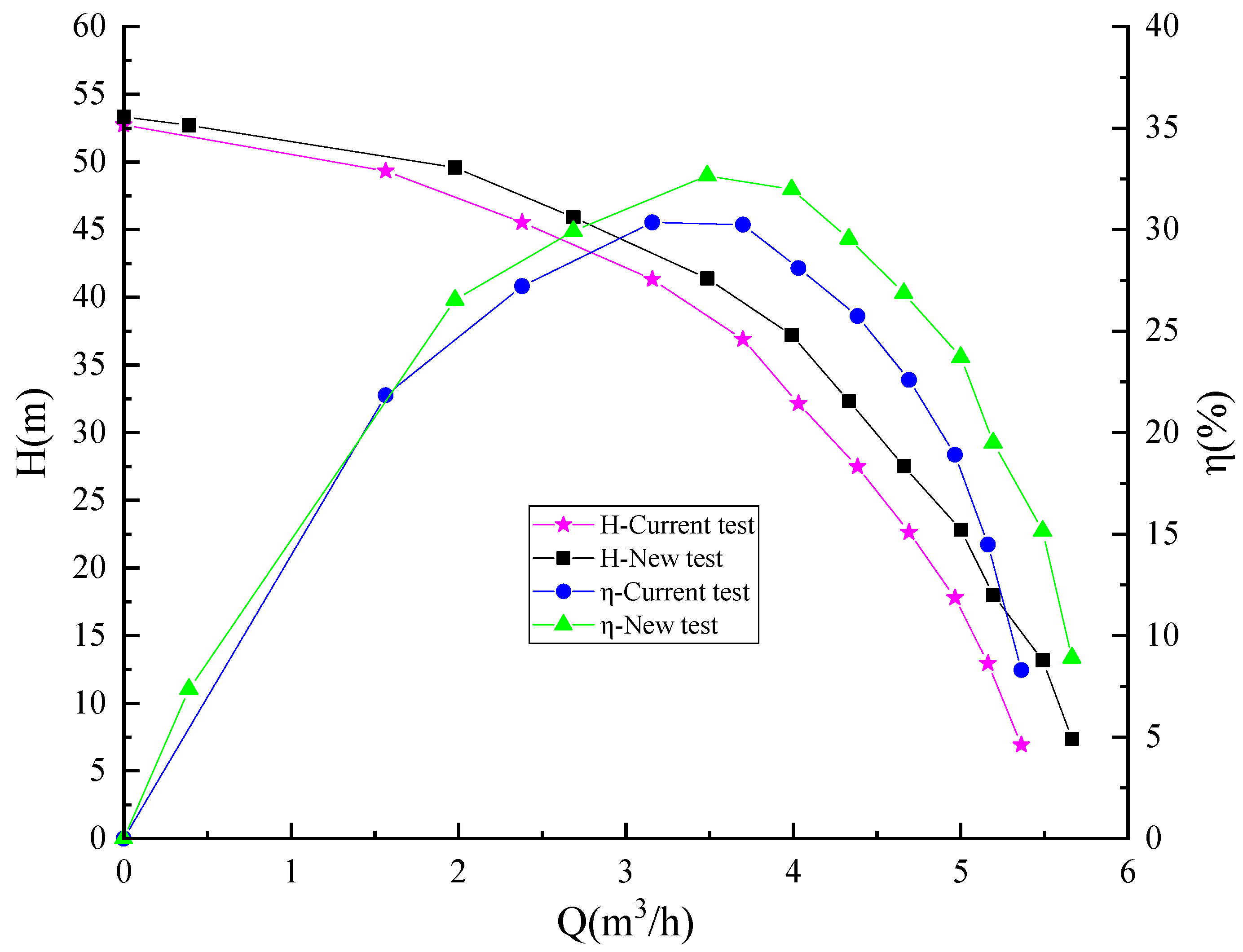
Figure 19 presents a comparison of the external characteristics test results between the models with and without auxiliary blades. The pump’s head and efficiency vary with the flow rate. It can be observed from the graph that the addition of auxiliary blades significantly increases the pump’s head at the same flow rate, greatly enhancing its hydraulic performance. In the vicinity of the optimal operating point, the pump’s head is approximately 8.1% higher compared to the original model. The auxiliary blades perform work on the fluid, resulting in increased power consumption by the motor. Additionally, with the introduction of auxiliary blades on the impeller, the pump’s volumetric losses are reduced. The interaction between these two energy factors can cause fluctuations in the overall pump efficiency. The experimental results indicate that the overall efficiency of the pump with auxiliary blades has improved. Near the optimal operating point, the overall efficiency is approximately 8.7% higher compared to the model without auxiliary blades. At low flow rates, there is a minimal improvement in head and overall efficiency. However, as the flow rate increases, the improvements in head and overall efficiency become more pronounced. At high flow rates, the pump with auxiliary blades achieves a head increase of approximately 116.45% and an overall efficiency increase of approximately 110.84% compared to the model without auxiliary blades. The peak efficiency of the pump near the optimal operating point shifts approximately 0.33 m3/h towards higher flow rates, which contributes to improving the pump’s water delivery capacity. During the rotation of the auxiliary blades, the pressure in the front chamber of the impeller is reduced, resulting in an increased axial force on the pump. Experimental validation confirms that the pump can operate properly with the increased axial force.
6. Conclusions
This study aimed to optimize the structure of multistage centrifugal pumps to reduce volumetric losses in the throat ring clearances based on the Tesla valve principle. The effectiveness of the proposed optimization approach was validated through a combination of numerical simulations and experimental tests. The main conclusions drawn from this study are as follows.
- (1)
- In the seal design of the multistage centrifugal pump’ throat ring gap, the Tesla valve principle can be applied. Utilizing the auxiliary blade structure to generate fluid impact can reduce throat ring leakage, thereby decreasing the volumetric loss of the multistage centrifugal pump.
- (2)
- After the addition of auxiliary blades, the head of the multistage centrifugal pump will increase under the same flow rate. The larger the flow rate, the more the pump’s head increases.
- (3)
- As the auxiliary blades rotate, they enhance the energy loss of the water pump while reducing volumetric loss. When the impeller diameter is 103 mm, the thickness of the auxiliary blade is 1.3 mm; when the radial length of the auxiliary blade is 1/4 of the impeller blade’s, the efficiency of the entire pump can be improved.
- (4)
- Auxiliary blades can cause the optimal operating point of the multistage centrifugal pump to shift towards the direction of a larger flow rate, thus improving the hydraulic performance of the pump.
- (5)
- The leakage of the multistage centrifugal pump throat ring varies with changes in flow rate. The larger the flow rate, the lower the throat ring leakage.
Author Contributions
Conceptualization, Y.G.; Software, H.Q. and Y.C.; Investigation, L.J.; Resources, W.L. All authors have read and agreed to the published version of the manuscript.
Funding
This study was sponsored by the National Key R&D Program Project (No. 2020YFC151 2405), the Key International Cooperative Research of the National Natural Science Foundation of China (No. 52120105010), the National Natural Science Foundation of China (No. 52179085), the Sixth “333 High Level Talented Person Cultivating Project” of Jiangsu Province, “Blue Project” initiatives in Jiangsu Colleges and Universities, and Project funded by China Postdoctoral Science Foundation (No. 2022TQ0127).
Data Availability Statement
The relevant data can be found in this article.
Conflicts of Interest
The authors declare no conflict of interest.
References
- Yan, J.; Zuo, Z.; Guo, W.; Hou, H.; Zhou, X.; Chen, H. Influences of wear ring clearance leakage on performance of a small-scale pump. Proc. Inst. Mech. Eng. Part A J. Power Energy 2020, 234, 454–469. [Google Scholar] [CrossRef]
- He, X.; Gong, W.; Deng, J.; Li, J.; Liang, L. Influence of impeller tip clearance on the performance of centrifugal refrigeration compressor. J. Xi’an Jiaotong Univ. 2019, 53, 30–37. [Google Scholar]
- Yang, C.; Qiang, P.; An, S.; Xu, N.; Liu, J. Effects of wear-ring clearance on performance of high-speed cetrifugal pump. Drain. Irrig. Mach. Eng. 2012, 35, 18–24. [Google Scholar]
- Zhao, C.; Han, X.; Cui, Z. Numerical simiulations of flow characteristics of wear-ring clearance in the centrifugal pump. Chin. J. Ship Res. 2020, 15, 159–167. [Google Scholar]
- Zheng, X.; Bu, X.; Sun, Z.; Xi, G. Leakage Characteristics of Wear Ring Clearance in Liquid Qxygen Turbo Pump under Thermodanamic Effect. J. Xi’an Jiaotong Univ. 2022, 56, 145–155. [Google Scholar]
- DaqiqShirazi, M.; Torabi, R.; Riasi, A.; Nourbakhsh, S. The effect of wear ring clearance on flow field in the impeller sidewall gap and efficiency of a low specific speed centrifugal pump. Proc. Inst. Mech. Eng. Part C J. Mech. Eng. Sci. 2018, 232, 3062–3073. [Google Scholar] [CrossRef]
- Zhang, S.; Li, H.; Xi, D. Investigation of the integrated model of side chamber, wear rings clearance, and balancing holes for centrifugal pumps. J. Fluids Eng. 2019, 141, 101101. [Google Scholar] [CrossRef]
- Zheng, L.; Chen, X.; Zhang, W.; Zhu, Z.; Qu, J.; Wang, M.; Ma, X.; Cheng, X. Investigation on characteristics of pressure fluctuation in a centrifugal pump with clearance flow. J. Mech. Sci. Technol. 2020, 34, 3657–3666. [Google Scholar] [CrossRef]
- Yan, C.; Liu, J.; Zheng, S.; Huang, B.; Dai, J. Study on the effects of the wear rings clearance on the solid-liquid two-phase flow characteristics of centrifugal pumps. Symmetry 2020, 12, 2003. [Google Scholar] [CrossRef]
- Li, W.; Li, E.; Ji, L.; Zhou, L.; Shi, W.; Zhu, Y. Mechanism and propagation characteristics of rotating stall in a mixed-flow pump. Renew. Energy 2020, 153, 74–92. [Google Scholar] [CrossRef]
- Li, W.; Huang, Y.; Ji, L.; Ma, L.; Agarwal, R.K.; Awais, M. Prediction model for energy conversion characteristics during transient processes in a mixed-flow pump. Energy 2023, 271, 127082. [Google Scholar] [CrossRef]
- Ji, L.; Li, W.; Shi, W.; Chang, H.; Yang, Z. Energy Characteristics of Mixed-Flow Pump under Different Tip Clearances Based on Entropy Production Analysis. Energy 2020, 199, 117447. [Google Scholar] [CrossRef]
- Ji, L.; Li, W.; Shi, W.; Tian, F.; Agarwal, R. Effect of Blade Thickness on Rotating Stall of Mixed-Flow Pump Using Entropy Generation Analysis. Energy 2021, 236, 121381. [Google Scholar] [CrossRef]
- Ji, L.; Li, W.; Shi, W.; Tian, F.; Agarwal, R. Diagnosis of internal energy characteristics of mixed-flow pump within stall region based on entropy production analysis model. Int. Commun. Heat Mass Transf. 2020, 117, 104784. [Google Scholar] [CrossRef]
- Ji, L.; He, S.; Li, W.; Shi, W.; Li, S.; Li, H.; Agarwal, R. Exploration of Blade Thickness in Suppressing Rotating Stall of Mixed Flow Pump. Arab. J. Sci. Eng. 2023, 48, 8227–8251. [Google Scholar] [CrossRef]
- Ji, L.; He, S.; Li, Y.; Li, W.; Shi, W.; Li, S.; Yang, Y.; Gao, Y.; Agarwal, R.K. Investigation of energy loss mechanism of shroud region in A mixed-flow pump under stall conditions. Proc. Inst. Mech. Eng. Part A J. Power Energy 2023, 09576509231162165. [Google Scholar] [CrossRef]
- Li, W.; Liu, M.; Ji, L.; Li, S.; Song, R.; Wang, C.; Cao, W.; Agarwal, R.K. Study on the trajectory of tip leakage vortex and energy characteristics of mixed-flow pump under cavitation conditions. Ocean Eng. 2023, 267, 113225. [Google Scholar] [CrossRef]
- Liu, H.; Du, X.; Wu, X.; Tan, M. Numerical simulation on gas-phase characteristics of gas-liquid two-phase flow in pump. J. Drain. Irrig. Mach. Eng. 2022, 40, 238–243. [Google Scholar]
- Liu, Z.; Zhang, Y.; Dai, Q.; Zheng, Y.; Wu, D.; Wei, W. Pressure pulsation characteristics and improvement methods of axial extension pump. J. Drain. Irrig. Mach. Eng. 2022, 40, 8–14. [Google Scholar]
- Kong, D.; Pan, Z.; Yang, B. Characteristics of gas-liquid two-phase flow in self-priming pump. J. Drain. Irrig. Mach. Eng. 2022, 40, 15–21. [Google Scholar]
- Stel, H.; Ofuchi, E.M.; Chiva, S.; Morales, R.E. Numerical simulation of gas-liquid flows in a centrifugal rotor. Chem. Eng. Sci. 2020, 221, 115692. [Google Scholar] [CrossRef]
- Huang, J.; Zheng, Y.; Kan, K.; Xu, Z.; Huang, C.; Zhou, G.; Du, Y. Hydraulic characteristics of reverse power generation of axial-flow pump. J. Drain. Irrig. Mach. Eng. 2022, 40, 230–237. [Google Scholar]
- Fu, J.; Li, H.; Fan, D.; Shen, W.; Liu, X. Modeling and Efficiency Prediction of Aeroengine Centrifugal Pump Integrated Loss Model Based on One-Dimensional Flow. J. Northwestern Polytech. Univ. 2018, 36, 807–815. [Google Scholar] [CrossRef]
- Gamboa, A.R.; Morris, C.J.; Forster, F.K. Improvements in fixed valve micropump performance through shape optimization of vlaves. J. Fluids Eng. 2005, 127, 339. [Google Scholar] [CrossRef]
- Wang, T.; Wang, H.; Lin, Y.; Chen, M.; Qian, J. Numerial study of hydrodynamic cavitation in Tesla valves. J. Chem. Eng. Chin. Univ. 2020, 34, 884–889. [Google Scholar]
- Tesla, N. Valvular Conduit. U.S. Patent 1,329,559, 3 February 1920. [Google Scholar]
- Mcdonald, J.C.; Duffy, D.C.; Anderson, J.R.; Chiu, D.T.; Wu, H.; Schueller, O.J.; Whitesides, G.M. Fabrication of microfluidic system in poly (dimethylsiloxane). Electrophoresis 2015, 21, 27–40. [Google Scholar] [CrossRef]
- Weng, X.; Yan, S.; Zhang, Y.; Liu, J.; Shen, J. Design, simulation and experimental study of a micromixter based on Tesla valve structure. Chem. Ind. Eng. Prog. 2021, 40, 4173–4178. [Google Scholar]
- Zhou, R.; Qiao, Y.; Zhang, Y.; Dai, Z. Simulating the performance of Tesla valve. Phys. Exp. 2020, 40, 44–50. [Google Scholar]
Figure 1.
Pump structure diagram.

Figure 2.
Water body model.

Figure 3.
Water body mesh.
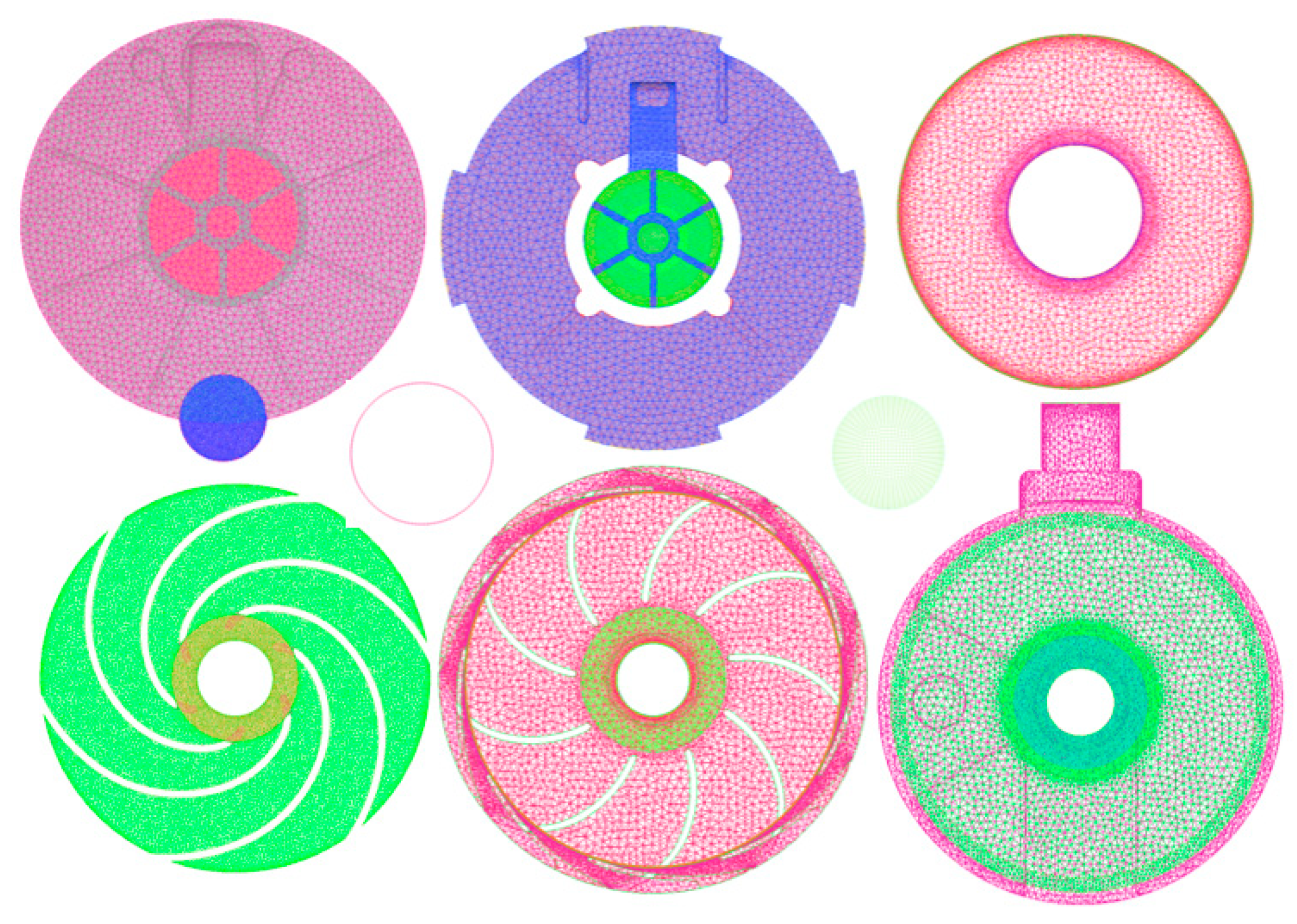
Figure 4.
Comparison of simulation and experimental results.
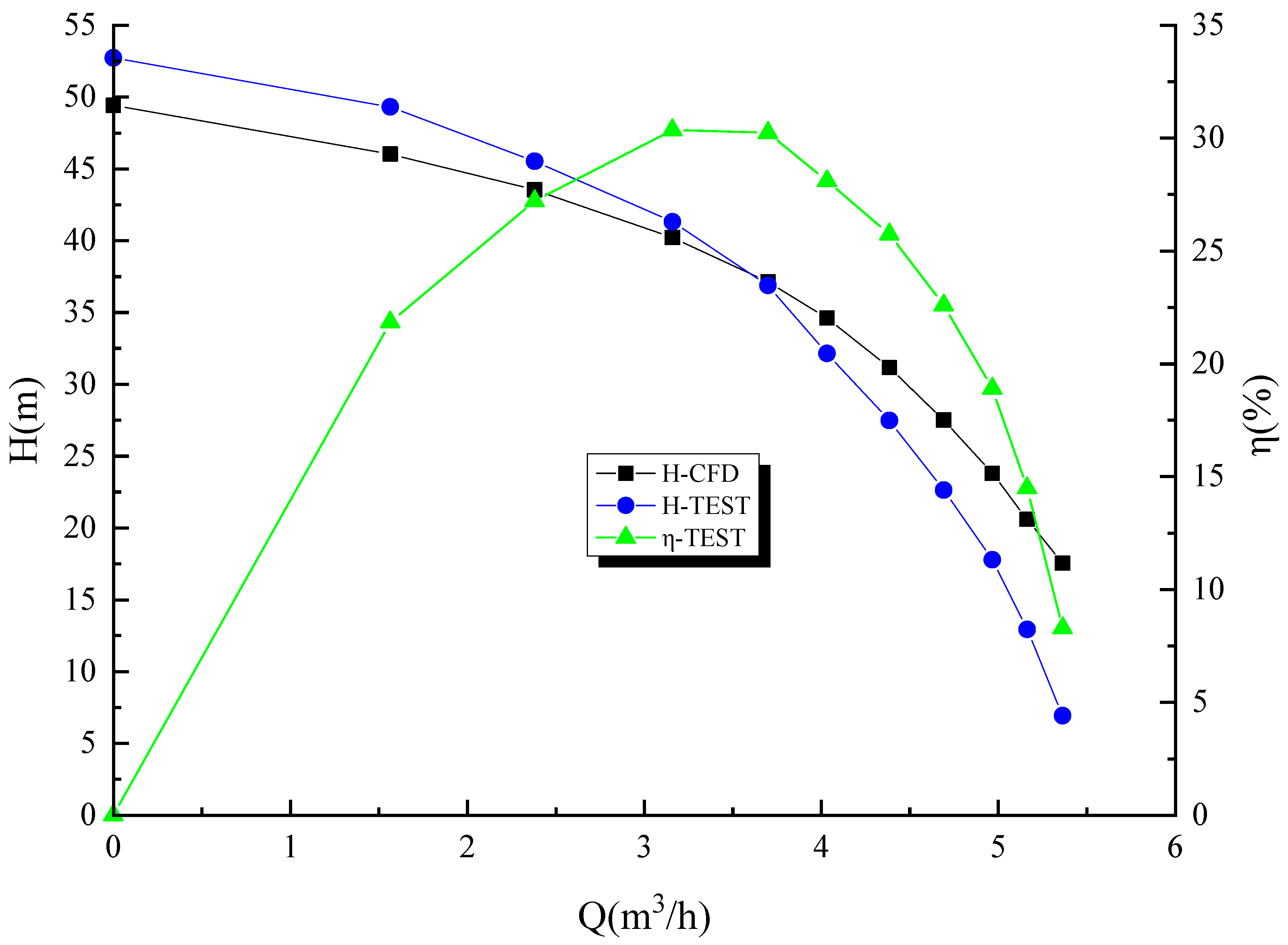
Figure 5.
Pressure contour of the pump and its mid-section.

Figure 6.
Velocity vector diagram for the pump and its mid-section.
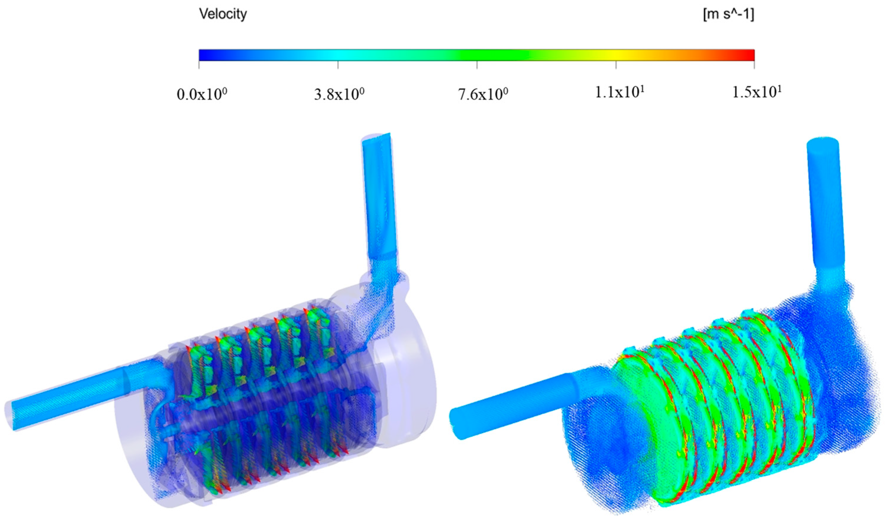
Figure 8.
Leakage rate under different working conditions.
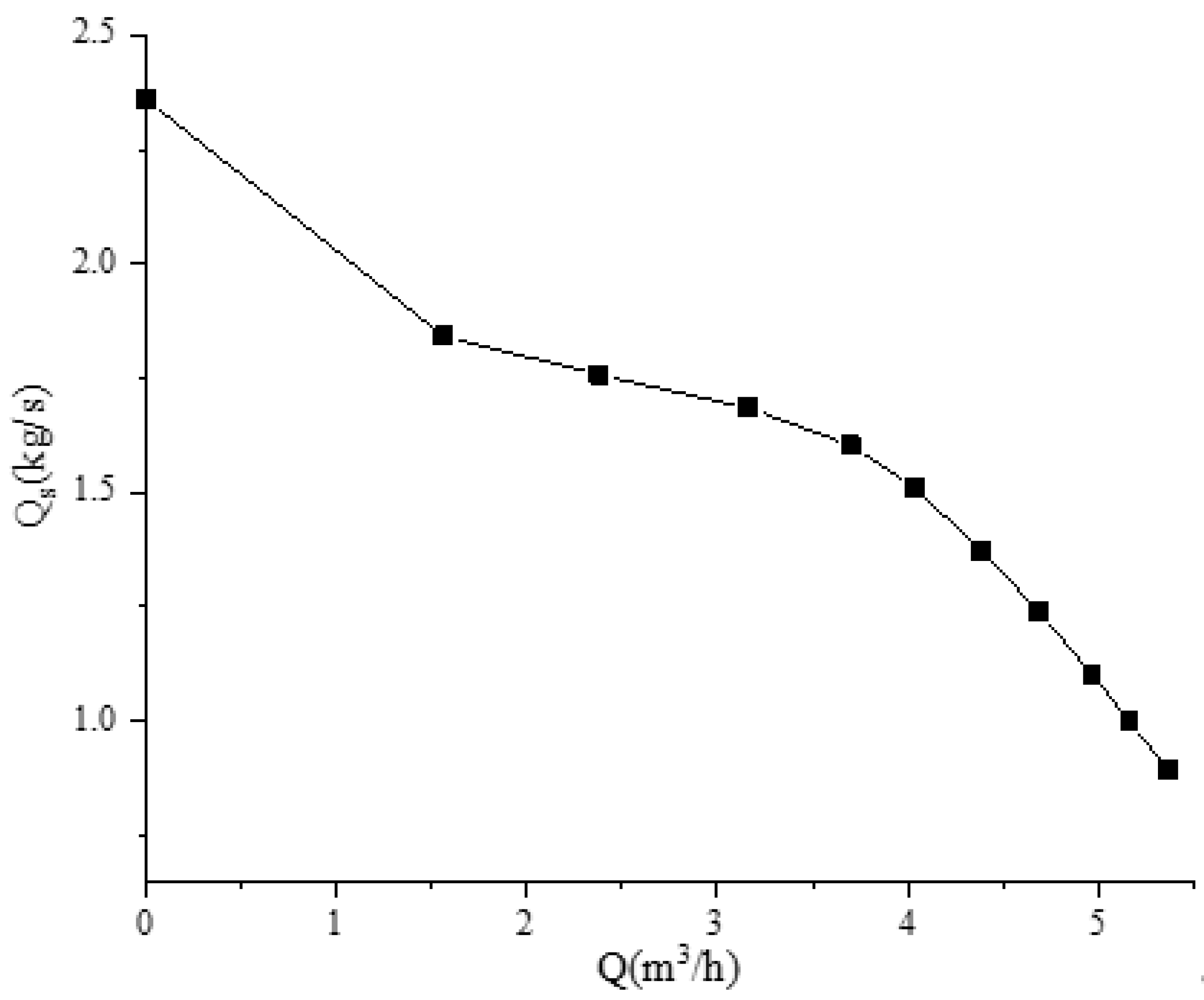
Figure 9.
(a) Forward; (b) Reverse. Diagram of the different flow directions of the Tesla valve.

Figure 10.
Impeller with auxiliary blades.

Figure 11.
Total pressure contour plots in pumps with and without auxiliary blades.
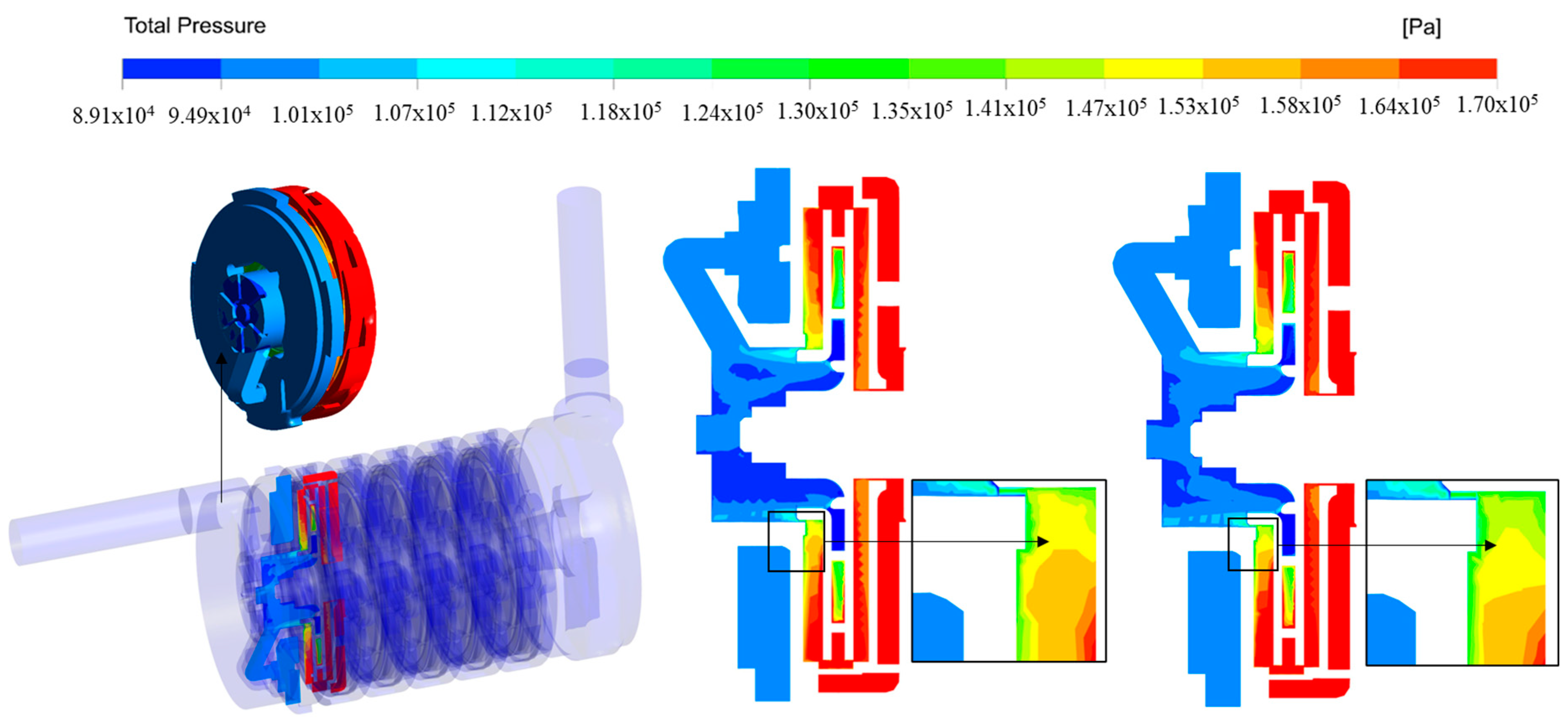
Figure 12.
Comparison of water velocity vectors in the front chamber of pumps with and without auxiliary blades.
Figure 12.
Comparison of water velocity vectors in the front chamber of pumps with and without auxiliary blades.
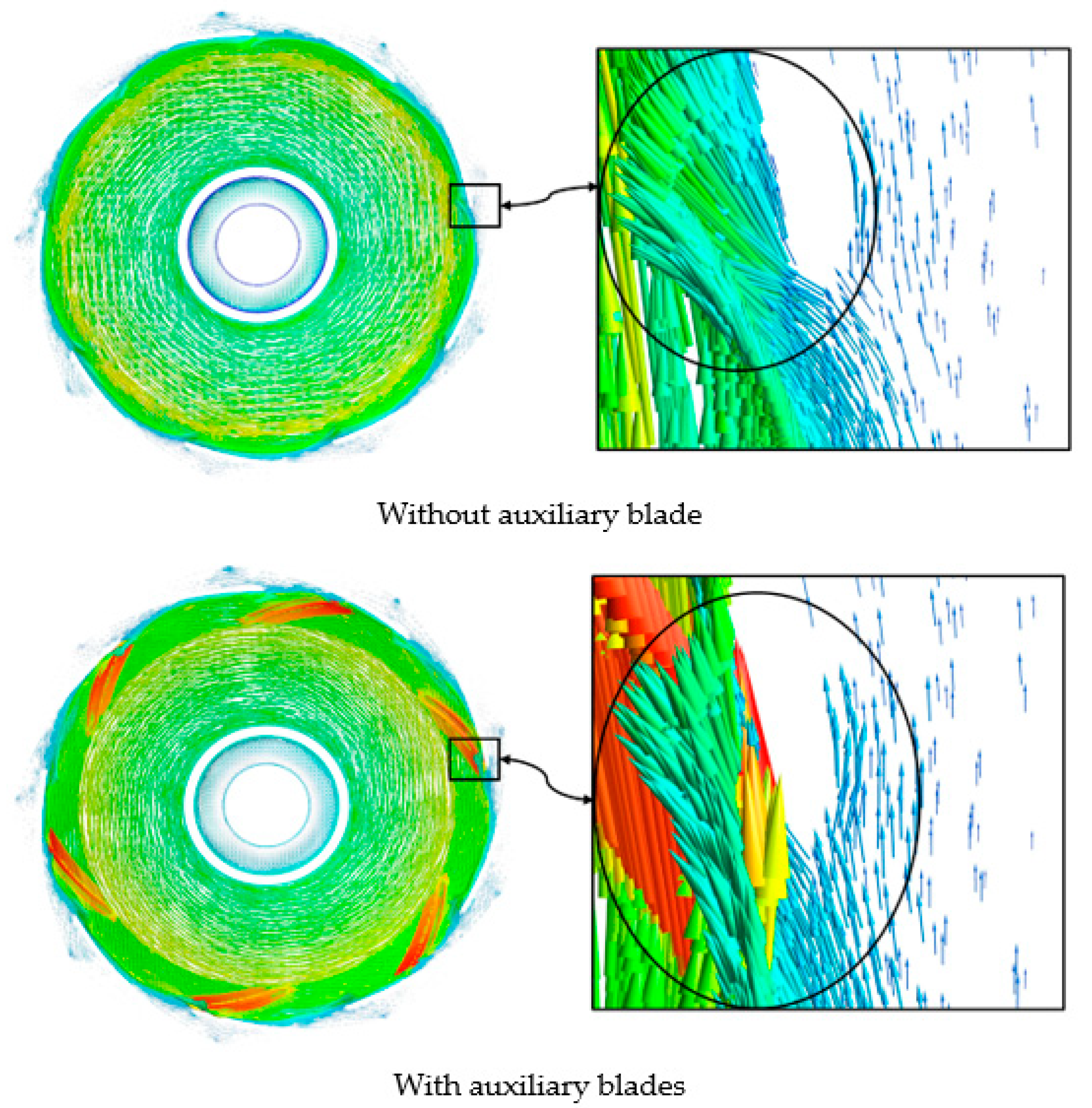
Figure 13.
Comparison of water velocity vectors at the throat ring of pumps with and without auxiliary blades.
Figure 13.
Comparison of water velocity vectors at the throat ring of pumps with and without auxiliary blades.
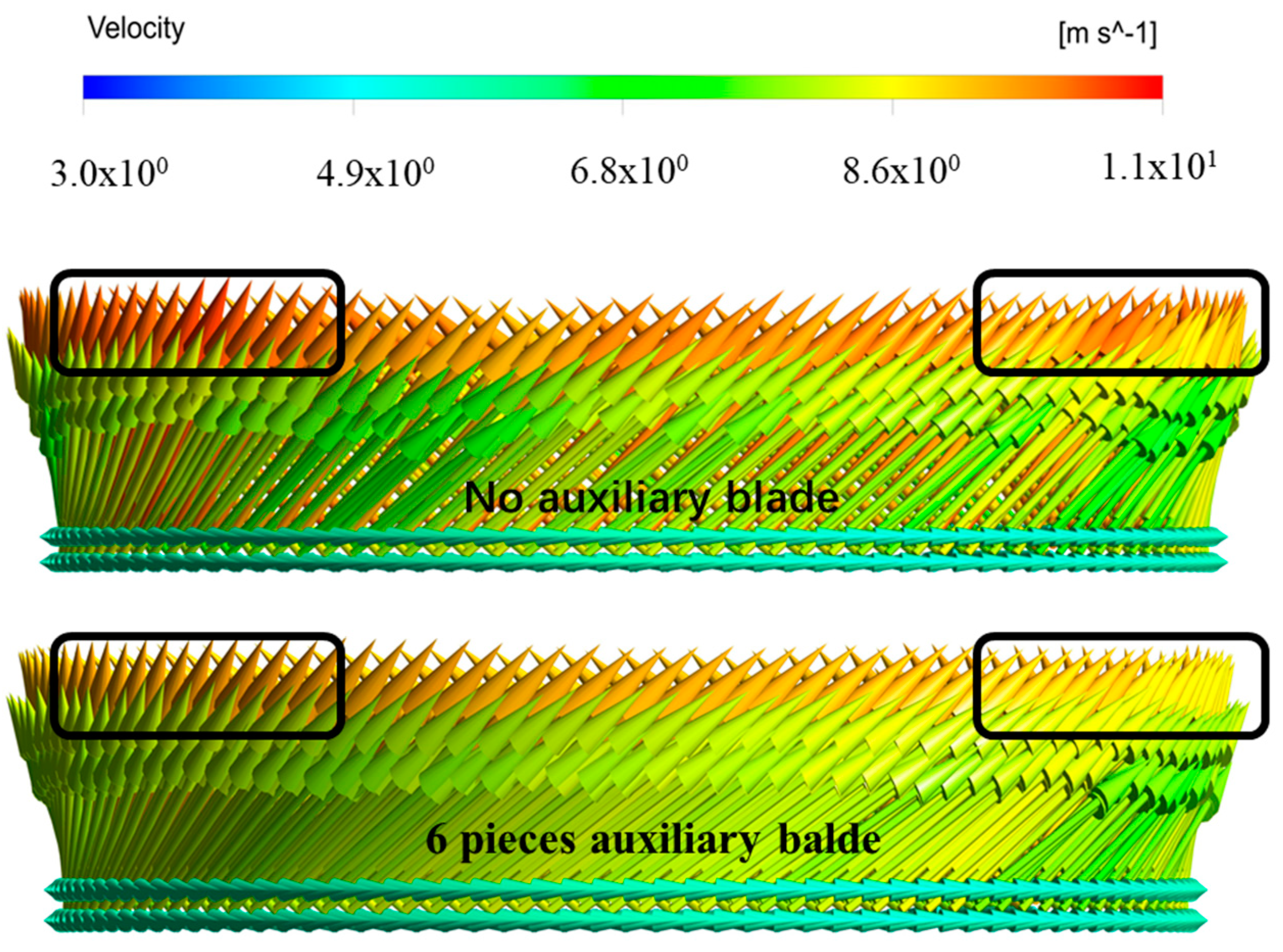
Figure 14.
Comparison of throat ring leakage in pumps with and without auxiliary blades.

Figure 15.
Comparison of simulated head in pumps with and without auxiliary blades.
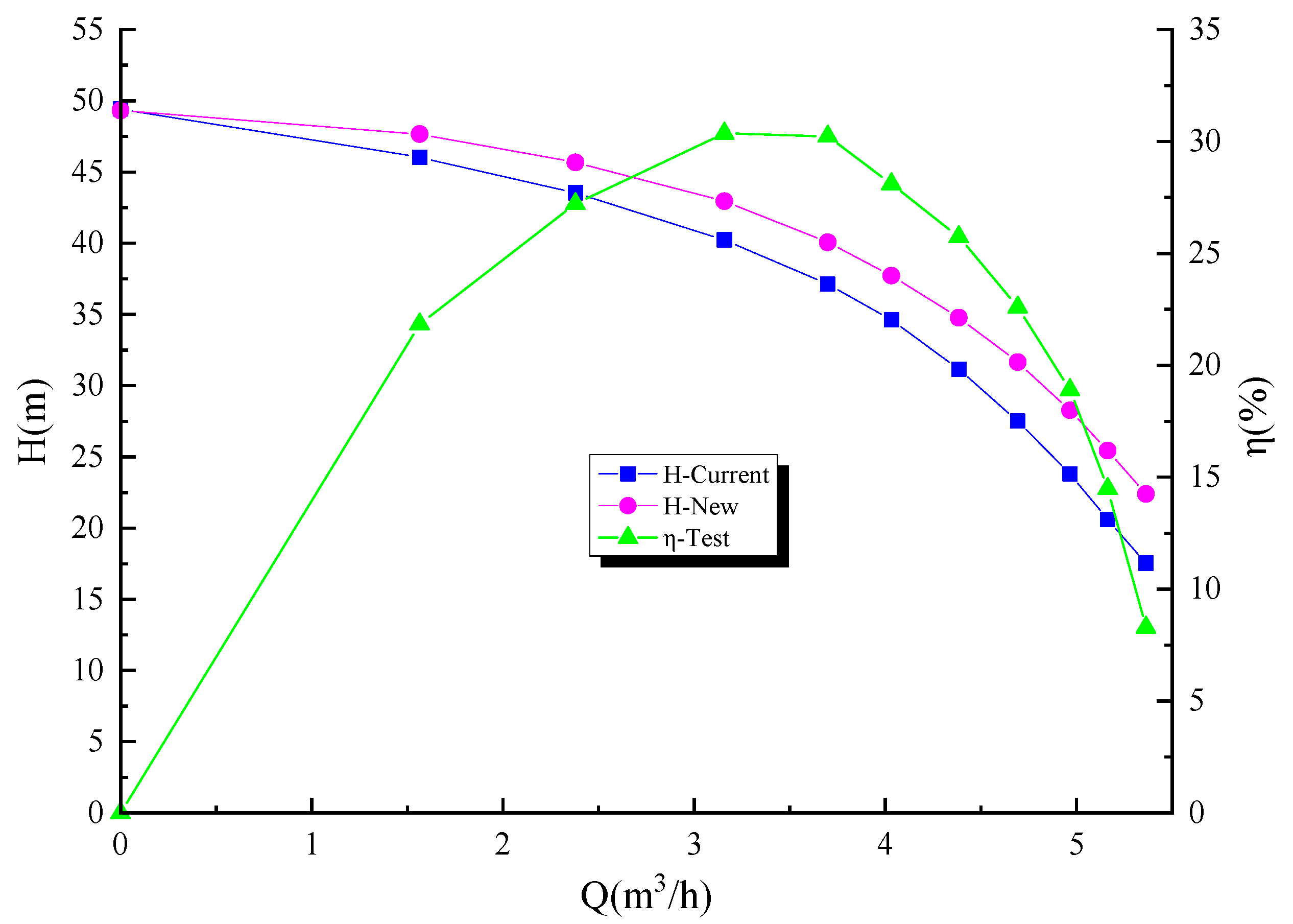
Figure 16.
Prototype of the impeller.
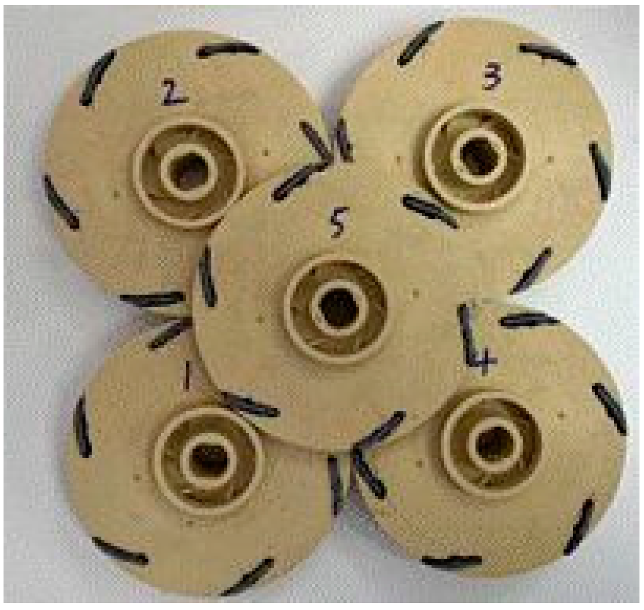
Figure 17.
Impeller after the experiment.
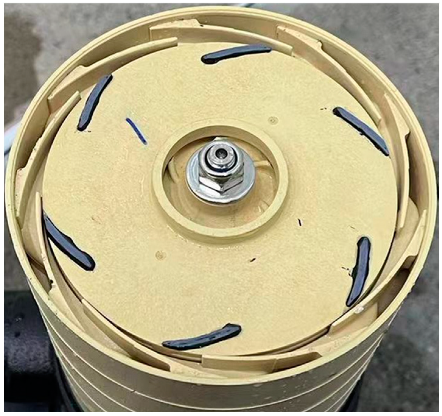
Figure 18.
Performance test.

Figure 19.
Comparison of performance experiment results of pumps with and without auxiliary blades.

Table 1.
Leakage rate of the throat ring at different working conditions.
| Leakage of Original Scheme | ||||||||||||
|---|---|---|---|---|---|---|---|---|---|---|---|---|
| Flow Rate Q m3/h | 0.00 | 1.56 | 2.38 | 3.16 | 3.70 | 4.03 | 4.38 | 4.69 | 4.97 | 5.16 | 5.36 | |
| Leakage Rate kg/s | Level 1 | 0.47 | 0.39 | 0.37 | 0.35 | 0.32 | 0.30 | 0.27 | 0.25 | 0.22 | 0.21 | 0.18 |
| Level 2 | 0.46 | 0.37 | 0.35 | 0.34 | 0.32 | 0.30 | 0.27 | 0.25 | 0.22 | 0.20 | 0.18 | |
| Level 3 | 0.47 | 0.36 | 0.35 | 0.34 | 0.32 | 0.30 | 0.28 | 0.25 | 0.22 | 0.20 | 0.18 | |
| Level 4 | 0.47 | 0.36 | 0.35 | 0.34 | 0.32 | 0.30 | 0.27 | 0.25 | 0.22 | 0.20 | 0.18 | |
| Level 5 | 0.49 | 0.36 | 0.35 | 0.33 | 0.32 | 0.30 | 0.27 | 0.25 | 0.22 | 0.20 | 0.18 | |
| All | 2.36 | 1.84 | 1.76 | 1.69 | 1.60 | 1.51 | 1.37 | 1.24 | 1.10 | 1.00 | 0.89 | |
Table 2.
Comparison of throat ring leakage rates in pumps with and without auxiliary blades.
| Serial Number | Flow Rate Q m3/h | Leakage Rate-Without Auxiliary Blade kg/s | Leakage Rate-With Auxiliary Blade kg/s | Amount of Leakage Reduction kg/s | Leakage Reduction Rate % |
|---|---|---|---|---|---|
| 1 | 5.36 | 0.89 | 0.64 | 0.26 | 28.99 |
| 2 | 5.16 | 1.00 | 0.75 | 0.25 | 24.60 |
| 3 | 4.97 | 1.10 | 0.85 | 0.25 | 22.59 |
| 4 | 4.69 | 1.24 | 0.99 | 0.25 | 20.25 |
| 5 | 4.38 | 1.37 | 1.11 | 0.27 | 19.35 |
| 6 | 4.03 | 1.51 | 1.23 | 0.29 | 18.89 |
| 7 | 3.70 | 1.60 | 1.32 | 0.29 | 17.97 |
| 8 | 3.16 | 1.69 | 1.42 | 0.26 | 15.60 |
| 9 | 2.38 | 1.76 | 1.52 | 0.24 | 13.74 |
| 10 | 1.56 | 1.84 | 1.68 | 0.16 | 8.57 |
| 11 | 0.00 | 2.36 | 2.18 | 0.18 | 7.70 |
Disclaimer/Publisher’s Note: The statements, opinions and data contained in all publications are solely those of the individual author(s) and contributor(s) and not of MDPI and/or the editor(s). MDPI and/or the editor(s) disclaim responsibility for any injury to people or property resulting from any ideas, methods, instructions or products referred to in the content. |
© 2023 by the authors. Licensee MDPI, Basel, Switzerland. This article is an open access article distributed under the terms and conditions of the Creative Commons Attribution (CC BY) license (https://creativecommons.org/licenses/by/4.0/).
Share and Cite
MDPI and ACS Style
Gao, Y.; Li, W.; Qi, H.; Ji, L.; Chen, Y. Optimized Design of a Multistage Centrifugal Pump Based on Volumetric Loss Reduction by Auxiliary Blades. Water 2023, 15, 2350. https://doi.org/10.3390/w15132350
AMA Style
Gao Y, Li W, Qi H, Ji L, Chen Y. Optimized Design of a Multistage Centrifugal Pump Based on Volumetric Loss Reduction by Auxiliary Blades. Water. 2023; 15(13):2350. https://doi.org/10.3390/w15132350
Chicago/Turabian StyleGao, Yi, Wei Li, Handong Qi, Leilei Ji, and Yunfei Chen. 2023. "Optimized Design of a Multistage Centrifugal Pump Based on Volumetric Loss Reduction by Auxiliary Blades" Water 15, no. 13: 2350. https://doi.org/10.3390/w15132350
Note that from the first issue of 2016, this journal uses article numbers instead of page numbers. See further details here.