Article

The Energy Efficiency of Hot Water Production by Gas Water Heaters with a Combustion Chamber Sealed with Respect to the Room

by
Grzegorz Czerski
* and
Andrzej Strugała
Faculty of Energy and Fuels, AGH University of Science and Technology, al. Mickiewicza 30, Krakow 31-464, Poland
*
Author to whom correspondence should be addressed.
Water 2014, 6(8), 2394-2411; https://doi.org/10.3390/w6082394
Submission received: 30 April 2014 / Revised: 27 June 2014 / Accepted: 23 July 2014 / Published: 11 August 2014
(This article belongs to the Special Issue Water Consumption and Water End-uses in Buildings)

Abstract

:
This paper presents investigative results of the energy efficiency of hot water production for sanitary uses by means of gas-fired water heaters with the combustion chamber sealed with respect to the room in single-family houses and multi-story buildings. Additionally, calculations were made of the influence of pre-heating the air for combustion in the chimney and air supply system on the energy efficiency of hot water production. CFD (Computational Fluid Dynamics) software was used for calculation of the heat exchange in this kind of system. The studies and calculations have shown that the use of gas water heaters with a combustion chamber sealed with respect to the room significantly increases the efficiency of hot water production when compared to traditional heaters. It has also been proven that the pre-heating of combustion air in concentric chimney and air supply ducts essentially improves the energy efficiency of gas appliances for hot water production.

1. Introduction

In recent years in developed countries, energy consumption in buildings has been increasing dramatically; in the EU, for example, it is greater than in the industry and transport sectors [1]. HVAC systems (heating, ventilation, air-conditioning) consume the highest amounts of energy in residential buildings [2]. On the other hand, according to [3], the biggest energy consumer worldwide is for hot water usage, its share in total residential energy consumption ranging from 11% to 32%. The high energy efficiency of domestic hot water production is therefore desirable due to the need to reduce the emission of greenhouse gases [4].
In residential buildings, hot water is produced by means of a number of appliances using energy either from fuel burning, or electric and solar energy, in addition to the use of heat pumps. Frequently, in order to produce hot water, gas appliances have been utilized, i.e., gas-fired instantaneous or storage water heaters, as well as gas combination boilers. In the case of gas-fired instantaneous water heaters, appliances with an open combustion chamber have thus far been used most frequently. They evacuate combustion gases by natural draft, and, therefore, the temperature of combustion gases has to be appropriately high (above 150 °C), which results in a relatively low efficiency of those appliances (80%–87% in relation to the lower heating value). Appliances with the combustion chamber sealed with respect to the room, only recently available on the market, are equipped with fans that enable a reduction of the temperature of the combustion gases to about 100 °C, resulting in a significant improvement in the energy efficiency of the appliances. High energy efficiency of these appliances is achieved also through the use of efficient heat exchangers. Additionally, it is possible to pre-heat air in the chimney and air supply ducts, which further improves energy efficiency. Moreover, the use of gas appliances with the combustion chamber sealed with respect to the room enables saving energy through a reduced demand for air necessary for the ventilation of the flats. It should be added that the basic advantage of these appliances is the safety of their usage. In the case of appliances with an open combustion chamber, there is a risk of their users being poisoned with toxic carbon monoxide [5,6,7]. People residing in neighboring apartments are also vulnerable to poisoning [8]. Additionally, the work of such a system can be negatively influenced by wind [9]. In the case of gas appliances with the combustion chamber sealed with respect to the room, the risk of combustion products reaching residential rooms is practically eliminated [10].
The heaters with the combustion chamber sealed with respect to the room require the use of an appropriate chimney and air supply systems. Former chimney systems used for appliances with an open combustion chamber were designed exclusively for evacuating combustion gases outside, while the new systems serve also for supplying air for combustion. There are two basic types of chimney and air supply ducts (Figure 1), in which:
-
the supply of air and evacuation of combustion gases is conducted with the use of a concentric duct;
-
the supply of air and evacuation of combustion gases is conducted with the use of two independent ducts.
In the case of concentric systems, the heat of combustion of the gases is recovered in order to pre-heat the air for combustion, which additionally increases the energy efficiency of such a system.
The aim of this paper is to show that the application of gas heaters with the combustion chamber sealed with respect to the room increases the energy efficiency of hot water production in residential buildings. To that end, results of investigations are presented concerning the energy efficiency of hot water production with the use of gas-fired instantaneous water heaters with the combustion chamber sealed with respect to the room both in single-family and in multi-story buildings. As the aforementioned efficiency improvement can be significantly influenced by the application of concentric chimney and air supply ducts, additionally, simulation calculations were made of the impact of pre-heating air in these ducts on the efficiency of hot water production. For the simulation of heat exchange in the chimney and air supply system, the CFD (Computational Fluid Dynamics) software was used.
Figure 1. Basic types of chimney and air supply ducts: (a)—concentric system; (b)—separate system.
Water 06 02394 g001

2. Methods

2.1. Experimental

The examinations of energy efficiency of gas-fired instantaneous water heaters with the combustion chamber sealed with respect to the room constituted one part of a project concerning the possibility of using these appliances in multi-story buildings. The investigations were divided into three stages, i.e.,
-
laboratory examinations of water heaters with the combustion chamber sealed with respect to the room;
-
examinations of water heaters operating in conditions of single family buildings;
-
examinations of water heaters operating in conditions of multi-story buildings.
The aim of the first stage was to determine the optimal operating conditions of the examined heaters and the impact of pressure losses in the chimney and air supply ducts on the parameters of the work. As the value of pressure losses in the ducts is crucial for the appropriate functioning of the heaters, during the investigations, the varying value of flow resistance in these ducts was simulated and its impact, among others, on the energy efficiency of the appliances was analyzed. The second stage of the investigations was conducted with the use of experimental equipment simulating a single-family building, whereby the operation of selected gas-fired instantaneous water heaters connected to different chimney and air supply systems was monitored. The impact of the kind of the chimney and air supply ducts, as well as their length on the operating parameters of the gas appliances was verified, including energy efficiency. For the purposes of the investigations, chimney and air supply ducts with lengths of 2, 4, 6, 8 and 10 m were used. In the case of the separate system, there were ducts with diameters of φ 80 mm and four duct elbows with φ 80 mm, while in the case of the concentric system, chimney and air supply ducts with diameters of φ 60 and φ 100 mm, respectively, were utilized as well as two duct elbows of φ 60/100 mm. These arrangements reflected the most widely applied operating solutions in single-family buildings. The characteristics of the gas-fired instantaneous water heaters with the combustion chamber sealed with respect to the room used at the first and second stages of the investigations is presented in Table 1. The thermal energy of hot water leaving the heater was adopted as the power of the gas appliance. The chemical energy of natural gas supplied to the heater determined by the lower heating value was adopted as heat input.
Table 1. Characteristics of gas-fired instantaneous water heaters with combustion chamber sealed with respect to the room used for first and second stages of investigations.
Gas appliancePower (kW)Heat input (kW)Fan power (W)
Appliance A7.0–20.89.0–27.067
Appliance B7.0–24.48.9–27.650
Appliance C8.6–19.511.1–22.678
The most important part of the project was the pilot test plant examination of selected solutions enabling hot water production under the conditions of a multi-story building. Both the separate as well as concentric collective chimney and air supply ducts systems were examined. The test plant simulated the work of collective chimney and air supply ducts in a type of building most common in Poland (five-storey). The selection of diameters while designing chimney systems was determined by the possibility of the appropriate operation of the system with maximal heat input as well as the possibility of fitting the systems inside the existing chimney channels in residential buildings. Each examined system was equipped with five gas appliances with the combustion chamber sealed with respect to the room, one for each floor. In the investigations a prototypical gas-fired instantaneous water heater with a power of 21 kW was used, which enabled its modification during the tests in order to maximally adapt the appliance to the chimney and air supply systems in multi-storey buildings. In the case of the separate system, the collective chimney and air supply ducts had a diameter of 120 mm each. In the case of the concentric system, the collective internal chimney duct had a diameter of 140 mm, and the external air supply duct of 200 mm. Moreover, the system consisted of 60/100 mm concentric chimney and air supply connection ducts, connected to the heater by means of a duct adapter.
In order to check the functioning of the analyzed systems in all possible operating arrangements of the gas appliances, the program of investigations involved measurements for the following cases:
-
working of only one water heater (the examinations were conducted separately for each floor);
-
simultaneous working of two, three and four water heaters (for all possible combinations);
-
simultaneous working of all the five water heaters.
In the case of simultaneous working of two, three and four water heaters, for the final result of the examined parameter, the arithmetic mean was given of all the possible operating combinations of a given appliance. The energy efficiency investigations of gas-fired instantaneous water heaters with the combustion chamber sealed with respect to the room were conducted based on procedures specified by the European standard EN 26:2002 [11]. The energy efficiency of water heaters was determined based on the equation:
Water 06 02394 i001
where,
  • m = mass of water collected during the examination (kg);
  • cw = heat capacity of water equals 4.186 × 10³ (MJ/kg °C);
  • Δt = water temperature increase (°C);
  • Vg = volume of dry gas consumed by the heater during the examination (m3);
  • Hi = lower heating value of burned gas (MJ/m3).
During the pilot plant examinations, the energy efficiency of the appliances was determined based on the quality parameters of combustion and temperature of combustion gases:
η = 100 − Q1Q2
Where,
  • Q1 = stack losses (%);
  • Q2 = incomplete combustion losses (%).
    Water 06 02394 i002
    Water 06 02394 i003
Where,
  • Vc = volume of combustion gases (m3);
  • cc = average heat capacity of combustion gases (MJ/kg °C);
  • tc = temperature of combustion gases (°C);
  • nco = carbon monoxide concentration in combustion gases (–);
  • Hi = lower heating value of carbon monoxide (MJ/m3).
During the laboratory examinations, a reference gas was used and for the test plant investigations, natural gas was applied. Basic parameters for gas appliances were determined, i.e., heat input, thermal power and gas heater efficiency. Combustion gases and air temperatures were also measured, i.e., the temperature of the combustion gases downstream of the heaters and at the outlet of the chimney ducts and the air temperature before the heaters. Additionally, for each case, the air-fuel ratio was determined, which is an important parameter characterizing the process of combustion in atmospheric burners applied in gas-fired instantaneous water heaters. Its value has a decisive impact on the combustion quality and energy efficiency [12]. An excessively low value may result in incomplete combustion, while an excessively high value leads to a reduction of the energy efficiency of the appliances and a deterioration of combustion quality.

2.2. Calculations

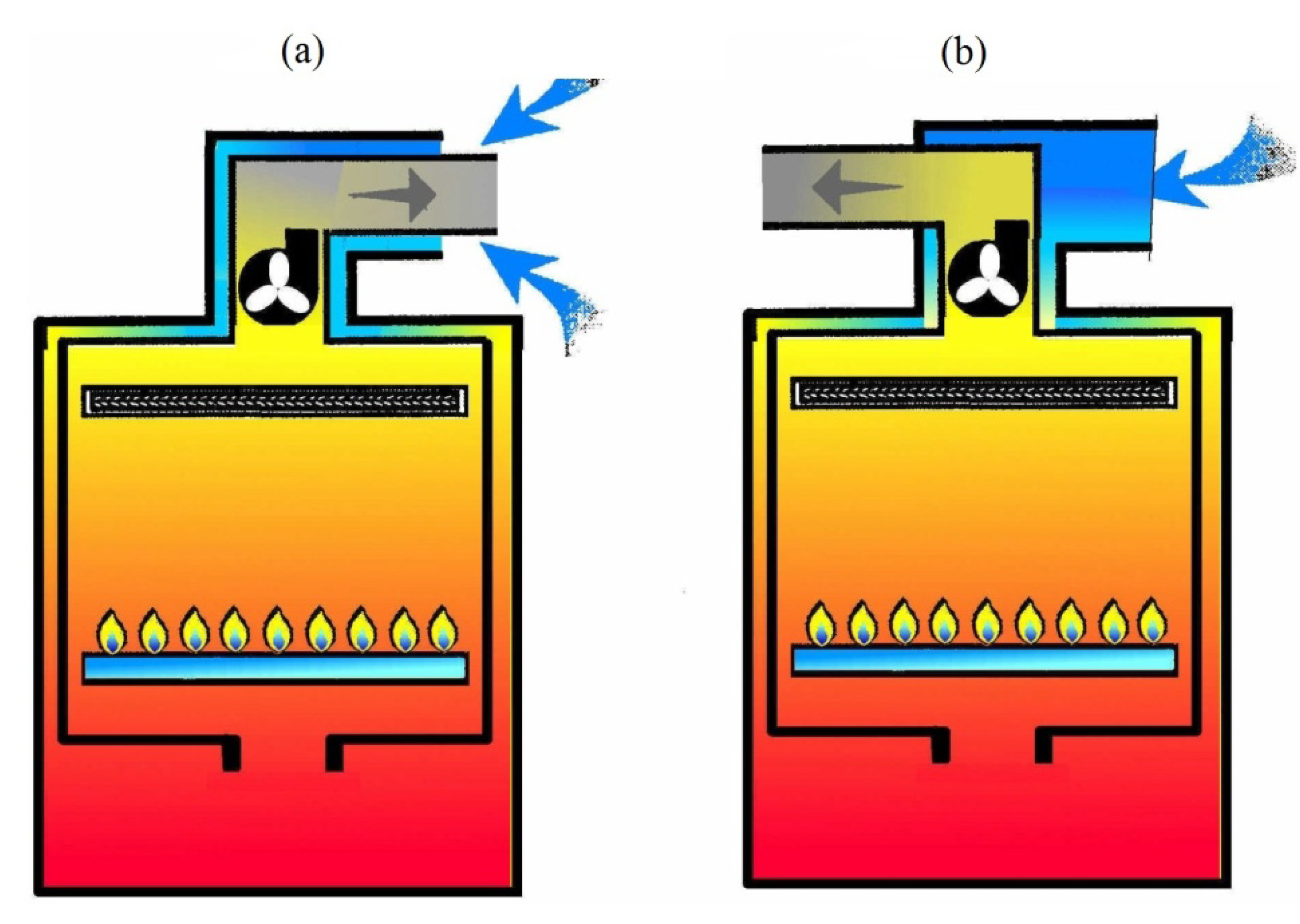
Based on experimental examinations, it is difficult to determine accurately how much of the augmentation in the efficiency of gas appliances with the combustion chamber sealed with respect to the room should be attributed to the pre-heating of air in the supply ducts. The conducted simulation calculations were aimed at explaining how the use of concentric chimney and air supply systems influences an improvement of energy efficiency of gas appliances. For the simulation calculations, the CFD Fluent software was used. This software enables the development of a numerical model which can be used, among other things, for calculating the heat exchange in concentric chimney and air supply ducts.
The CFD simulation calculations of heat exchange in chimney and air supply ducts consisted of three stages. The first stage of simulation, conducted for the conditions of single-family buildings, was aimed at determining the impact of the pre-heating of air in a single concentric chimney and of the air supply system on the energy efficiency of gas appliances. Additionally, the obtained results of calculations and the results of earlier measurements were compared. Obtaining a satisfactory compliance of calculation results with the measurements confirmed the usefulness of the applied software for further simulation calculations. The second stage of the simulation concerned the operating conditions of a concentric collective chimney and air supply system in multi-story buildings, and, particularly, the impact of using this system on the energy efficiency of gas appliances. In the course of these calculations, the results of experimental investigations (the input data for calculations) were utilized, as well as the experience gained during the first stage of the simulation calculations. In order to verify the results of calculations for the collective system, the third stage of simulation was conducted, during which additional calculations were made using the data obtained during the examinations of the collective concentric chimney and air supply ducts.
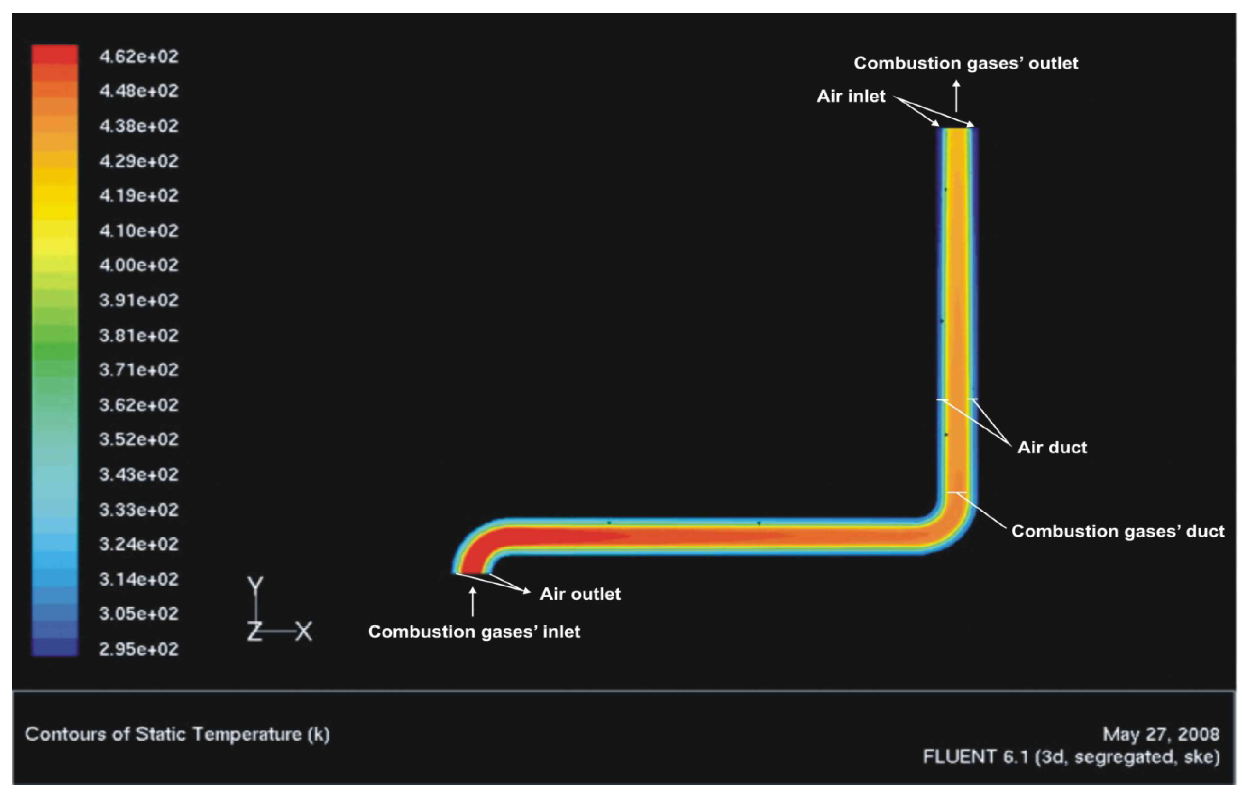
In the course of the calculations, the k-epsilon turbulence model was applied. Geometries and computational meshes were created by means of the Gambit application, and the results of the aforementioned measurements of a gas-fired instantaneous water heater with a power of 19.5 kW, connected to different chimney and air supply ducts, were used as the input data for the calculations. The mass flow rates of combustion gases and air were determined based on the composition of the gas applied during the measurements and on the air-fuel ratio. The dimensions and properties of the chimney and air supply ducts pre-set for the calculations were the same as those used for the aforementioned examinations. In the calculations, the phenomenon of natural gravity draft in the chimney and air supply ducts was also taken into consideration. During the calculations, heat exchange between the air supply duct and the chimney duct was modeled.
The simulation calculations was aimed at determining the average temperature of air and combustion gases in the chimney system. Based on the increase in temperature and the amount of air, the change of its enthalpy was determined. Next, relating the change of enthalpy of air to the amount of energy supplied with the combusted gas, an increase in the energy efficiency of the gas appliance caused by the pre-heating of air in the concentric chimney and air supply duct system was determined. In a similar way, a change in the enthalpy of combustion gases was determined (each time taking into consideration their composition). The difference in the enthalpy of combustion gases and air is the part of heat passed on to the surroundings, and it can be treated as heat losses in the chimney and air supply duct.
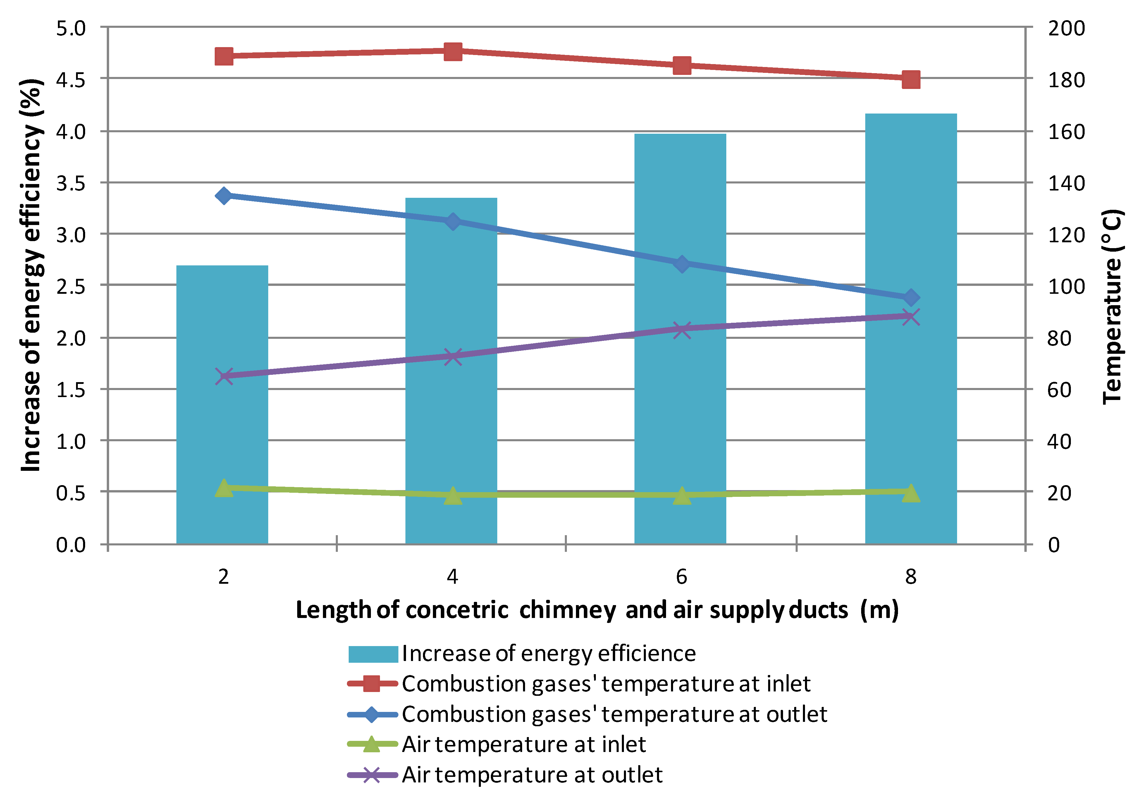
In the case of single concentric chimney and air supply duct systems, the impact of their length on the improvement of the energy efficiency of gas-fired water heaters was evaluated. The dimensions and properties of chimney and air supply ducts pre-set for the calculations were the same as those used during the examinations, i.e., concentric chimney and air supply ducts with diameters of φ 60 and φ 100 mm, respectively, and lengths of 2, 4, 6 and 8 m, as well as two duct elbows of φ 60/100 mm.
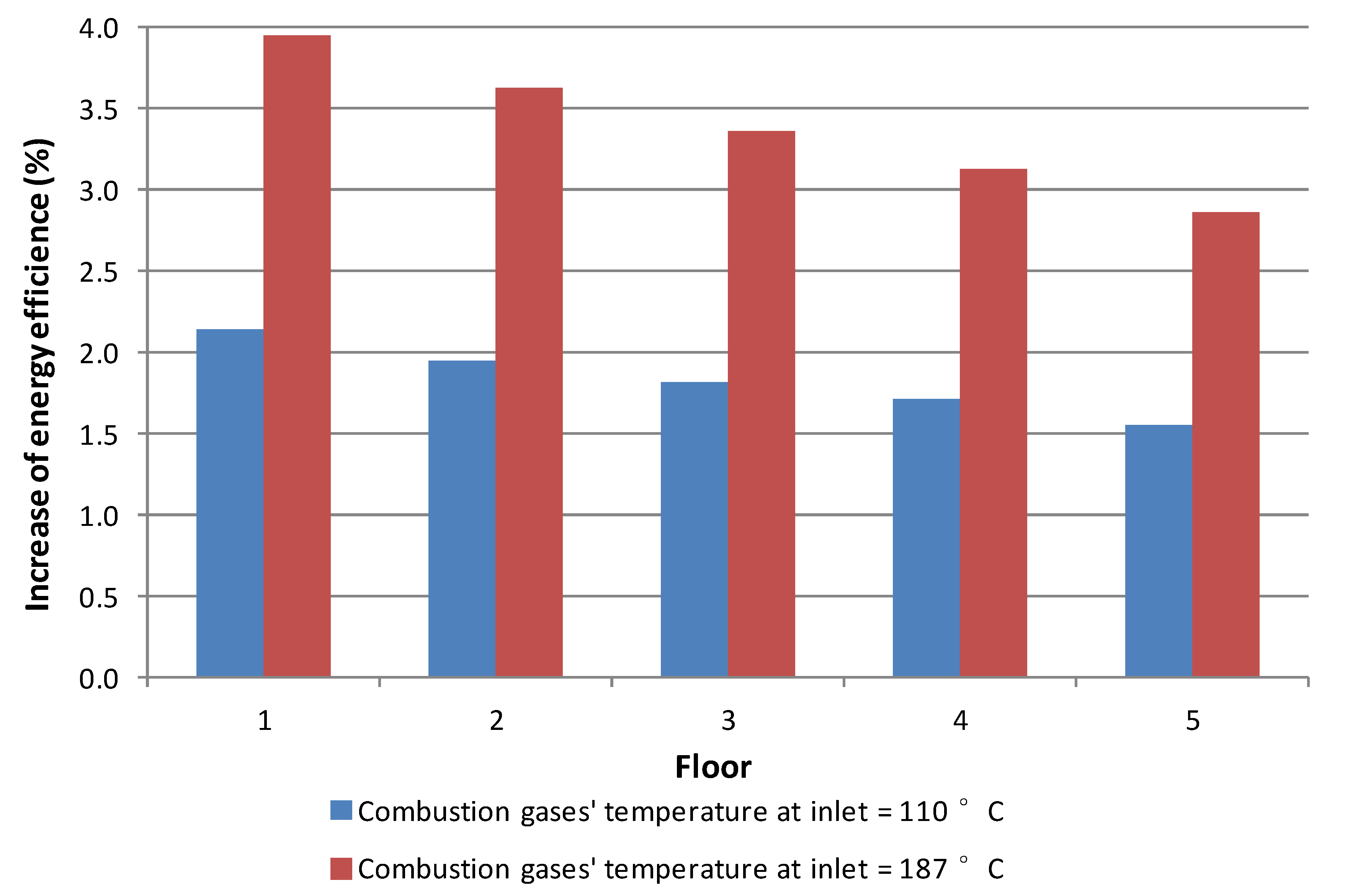
In the case of collective concentric ducts, the calculations were conducted for two values of temperature at the inlet, i.e., 110 °C and 187 °C in order to check the impact of temperature on the heat exchange and the obtained temperatures of air at the outlet. A typical temperature of the combustion gases for gas boilers is 110 °C, whereas 187 °C is typical for gas-fired water heaters. It was assumed that the air temperature at the inlet to the chimney system is 20 °C. The dimensions and other parameters of collective chimney and air supply ducts adopted for the calculations were the same as those used during the experimental investigations. It was assumed that the gas appliances were connected to a collective duct every 3 meters, and the height of the vertical collective ducts was 15 m. The diameters of collective ducts were 140 mm for the chimney duct and 200 mm for the air supply duct. The diameter of the connection ducts, 60/100 mm was adopted (which is a standard diameter used by gas appliances producers), and their length, 1 m. There was one duct elbow in each connection duct. Such an arrangement seems to most closely resemble the actual conditions. It was assumed that all five appliances were working with full power and with a relatively high air-fuel ratio reaching 1.8 (the upper limit of the optimal value determined at the first and the second stage of the examinations). In the calculations, the coincidence factor of the appliances operation was not taken into consideration, assuming that the simultaneous working of five water heaters can take place only in certain situations (in the period before Christmas or Easter, at weekends, etc.). Moreover, due to such an approach, the results of calculations can also be related to the work of gas combination boilers (which work, practically, in a continuous way) connected to the collective chimney systems.
In order to check if the results of simulations conducted with the use of the CFD Fluent software corresponded with the real conditions of collective chimney and air supply duct systems, a comparison was made of the calculated values of temperatures of air and combustion gases and the results obtained during the measurements. It required another series of simulation calculations that utilized the real data (the heat input, the air-fuel ratio and the combustion gases temperatures for appliances on particular floors) obtained during the test plant examinations. Table 2 lists the experimental data used during the calculations. The temperature of air at the inlet of the air supply duct was 20 °C. During the calculations, the same computational mesh was used as the one applied earlier.
Table 2. Input data for verification calculations.
Input dataFloor 1Floor 2Floor 3Floor 4Floor 5
Air-fuel ratio, (–)1.81.51.81.71.6
Heat input, (kW)19.620.119.820.220.1
Air-flow rate, (kg/h)43.437.143.842.239.5
Combustion gases flow rate, (kg/h)45.038.745.443.941.2
Combustion gases temperature at inlet, (°C)105111107111108

3. Results and Discussion

3.1. Results of Examinations

During the examinations, a number of operating parameters for the appliances were determined. Among the most important ones was the quality of combustion and energy efficiency of the appliances. In earlier papers [13,14,15], an analysis was presented of the appropriateness of the functioning of single and collective chimney and air supply duct systems. In the present paper the authors focused on a detailed analysis of the energy efficiency of the examined systems in order to show that the use of gas-fired instantaneous water heaters with the combustion chamber sealed with respect to the room increases the energy efficiency of hot water production in residential buildings when compared to widely used appliances with an open combustion chamber.

3.1.1. Laboratory Examinations

During the laboratory investigations on the impact of pressure losses in the chimney and air supply ducts on the functioning of the gas-fired instantaneous water heaters with the combustion chamber sealed with respect to the room, it was shown that with expanding pressure losses, the efficiency of the heaters increases (Table 3). This is mainly a result of a reduced value of the air-fuel ratio caused by a decrease in fan capacity. The determined values of efficiency for the examined heaters were contained in a broad range from 84.5% up to 93.7%. The optimal range of the air-fuel ratio for which the heaters reached high efficiencies (above 90%) was 1.5–1.9. It should be added that the registered efficiencies were determined not only by the air-fuel ratio but also by the structural details of the examined appliances and, particularly, the power of the installed fan (for the same values of the air-fuel ratio, the varying efficiencies of the examined heaters were recorded).
Table 3. Examination results of pressure losses influencing energy efficiency of various appliances.
Gas appliancePressure losses, (Pa)Energy efficiency, (%)Air-fuel ratio, (–)
Appliance A084.52.8
3785.82.6
8088.82.4
10591.91.9
11693.01.7
Appliance B088.82.3
3290.21.9
6791.41.8
8893.11.7
10093.71.5
Appliance C085.62.5
3086.52.4
7788.72.1
10588.91.9
11090.91.8

3.1.2. Single-Family Buildings

At the second stage of the investigations, during the measurements conducted in a single-family building, it was demonstrated that with increasing chimney and air supply duct length, the efficiency of each examined system also increased (Table 4). This expansion resulted from the reduced air-fuel ratio due to an increased flow resistance and, in the case of concentric ducts, also due to air pre-heating. For the examined heaters, the determined efficiencies were within the range of 89.5%–97.6%. For the same lengths of the air supply and chimney ducts, the difference in efficiency for the separate and concentric system for each of the examined appliances was about 5%. The highest energy efficiencies were recorded for the air-fuel ratio within the range of 1.3–1.8. In the case of appliance B (the heater which had a fan with insufficient power) connected to the concentric duct, it was possible to carry out examinations only for 2 m and 4 m ducts. In the case of longer ducts, the heater was switched off by a presostat, i.e., a device preventing an excessive pressure drop in the chimney and air supply ducts. In the case of appliance C, equipped with a more powerful fan, it was possible to conduct examinations for the concentric chimney and air supply ducts with a length of up to 10 m.
Table 4. Examination results for single family buildings.
Gas applianceLength of chimney and air supply ducts, (m)Pressure losses, (Pa)Energy efficiency, (%)Air-fuel ratio, (–)
Appliance B Separate system24991.42.4
46192.32.3
66792.62.2
86993.51.7
107394.21.6
Appliance B Concentric system25797.11.6
47397.71.3
Appliance C Concentric system28789.51.9
410392.11.8
611593.61.8
812795.21.6

3.1.3. Multi-Story Buildings

Table 5 presents results of investigations for the separate system and Table 6 for the concentric system that were conducted in a test plant simulating the conditions of collective chimney and air supply duct systems in multi-story buildings.
In the case of the separate system, a much higher efficiency was recorded (93%–96%) when compared to traditional heaters with the open combustion chamber (max. 87%). This resulted from the low temperature of combustion gases at the outlet of the examined prototypical appliances (92–130 °C), which had an increased surface of heat exchange. Moreover, the air supplied to the heaters was pre-heated by ca. 7–10 °C in a short connection duct. The number of appliances working simultaneously improves the efficiency only slightly. The air-fuel ratio for the separate systems fluctuated within the range of 1.3–1.9. Its value decreased with the rising number of simultaneously working appliances and the lower its value, the higher the efficiency became.
For the concentric system, the energy efficiencies were even higher. It can be assumed that the energy efficiency determined for the parameters of the combustion gases at the outlet of the collective chimney duct approximately corresponds with the mean value for all the appliances working at a given time. The registered efficiencies were contained within the range of 96%–97%. An increase in efficiency resulted mainly from the air pre-heating in the concentric air supply duct. At ambient temperature, equal to ca. 20 °C, the temperature of the pre-heated air at the inlets to the heaters ranged from 36 to 54 °C. The rise in temperature was dependent on the location of the heater (the lower the floor, the more the temperature rose) as well as on the number of simultaneously working appliances. The air-fuel ratio for the concentric system had higher values (1.4–2.1) than for the separate one. This resulted from the greater diameters of collective ducts in the case of the concentric system. The higher air-fuel ratio has a negative impact on the efficiency of the heaters, but the air pre-heating fully compensates for this impact.
The investigation results both for the single and collective systems proved the higher efficiency of hot water production with the use of the gas-fired instantaneous water heaters with the combustion chamber sealed with respect to the room when compared to traditional heaters. It is especially recommended to connect such appliances to a concentric chimney and air supply duct systems.
Table 5. Experimental results for the separate system in multi-story buildings.
CaseEnergy efficiency, (%)Air-fuel Ratio, (–)Air temperature, (°C)Combustion gases temperature, (°C)
One heater working
Floor 194.11.622112
Floor 295.31.61999
Floor 394.81.617101
Floor 495.71.619101
Floor 593.11.924124
Two heaters working
Floor 194.11.621115
Floor 295.41.71897
Floor 394.91.816107
Floor 495.41.620106
Floor 592.91.919130
Three heaters working
Floor 194.31.519116
Floor 296.01.61995
Floor 394.91.718105
Floor 495.41.520107
Floor 593.11.821128
Four heaters working
Floor 195.11.423114
Floor 296.11.41993
Floor 395.11.619104
Floor 495.71.422101
Floor 593.21.824123
Five heaters working
Floor 195.31.422106
Floor 296.11.41892
Floor 395.51.51899
Floor 495.91.32299
Floor 593.61.825123
Table 6. Experimental results for the concentric system in multi-story buildings.
CaseEnergy efficiency, (%)Air-fuel ratio, (–)Air temperature, (°C)Combustion gases temperature, (°C)
One heater working96.8 *
Floor 197.82.14948
Floor 297.11.84855
Floor 397.02.14755
Floor 496.31.84160
Floor 595.81.84265
Two heaters working97.1 ** 63 ***
Floor 1-2.050-
Floor 2-1.748-
Floor 3-2.046-
Floor 4-1.743-
Floor 5-1.640-
Three heaters working96.1 ** 84 ***
Floor 1-1.949-
Floor 2-1.646-
Floor 3-1.946-
Floor 4-1.744-
Floor 5-1.636-
Four heaters working96.3 ** 88 ***
Floor 1-1.751-
Floor 2-1.451-
Floor 3-1.849-
Floor 4-1.842-
Floor 5-1.639-
Five heaters working96.4 ** 86 ***
Floor 1-1.854-
Floor 2-1.552-
Floor 3-1.850-
Floor 4-1.744-
Floor 5-1.638-
Notes: * average efficiency for all floors; ** efficiency determined for the outlet of the collective chimney duct; *** combustion gases temperature at the outlet of the collective chimney duct.

3.2. Results of Calculations

In the paper [16], detailed results of calculations were presented, as well as a verification of the CFD numerical model for the single concentric chimney and air supply duct system. As good compliance of the calculation results with the experimental data was obtained, the acquired experience was used for further simulation calculations for the collective system.

3.2.1. Single Concentric Chimney and Air Supply Duct System

The impact of air pre-heating in the single chimney and air supply ducts on the energy efficiency of gas-fired water heaters is presented in Figure 2. For concentric ducts with length ranging from 2 to 8 m, the increase in energy efficiency caused by air pre-heating is significant and, depending on the duct length, ranges from 2.7% to 4.2%. The increase of energy efficiency related to 1 m is not linear and it decreases with the lengthening of the ducts. The fact that the temperature of the combustion gases at the outlet of the appliance decreases with the lengthening of the ducts is also significant. Heat losses for the chimney and air supply duct system are equal to ca. 1%.
Figure 2. Increase in energy efficiency of gas appliance, as well as temperature of air and combustion gases at the inlet and at the outlet of a single concentric chimney and air supply duct system.
Water 06 02394 g002
A sample temperature distribution for the concentric chimney and air supply ducts with a length of 2 m is presented in Figure 3. It can be seen that the temperature of the combustion gases and air falls with the widening of the distance. In the case of the combustion gases, this concerns the distance from the duct axis and, in the case of air, the distance from the internal wall of the duct. As a final result of the calculations of the temperature of air and combustion gases at the outlet of the chimney and air supply duct systems, the mean temperature for the given cross section area was adopted from the CFD calculations.
Figure 3. Sample temperature distribution (K) for the single chimney and air supply duct system with a length of 2 meters.
Water 06 02394 g003
As stated previously, two factors are responsible for the total increase in the energy efficiency of a gas appliance connected to the concentric chimney and air supply duct systems, i.e., the air-fuel ratio and the air temperature at the inlet to the heater. A difference in the energy efficiency for appliances with concentric and separate ducts with a length of 2 m was equal to ca. 5.0%. From the results of calculations it can be concluded that air pre-heating improves the efficiency by ca. 2.7%. It is therefore responsible for more than a half of the total increase in the efficiency of the appliance.

3.2.2. Collective Concentric Chimney and Air Supply Duct System

The calculated temperatures of air and combustion gases for the collective concentric duct system are shown in Table 7 and the increase in the energy efficiency due to air pre-heating is given in Figure 4.
Table 7. Calculated temperature of combustion gases and air for the collective concentric chimney and air-supply duct system.
Temperature of Combustion Gases at Inlet, (°C)110187
Air Temperature at Outlet, (°C)
Floor 155.485.4
Floor 252.480.0
Floor 350.175.7
Floor 448.571.7
Floor 545.767.5
Combustion gases at outlet, (°C)79.9131.4
Figure 4. Increase in energy efficiency of gas appliance on each floor for different temperatures of combustion gases at inlet.
Water 06 02394 g004
Maximal augmentation of temperature of the pre-heated air was recorded for the first floor (35 °C for the inlet temperature of combustion gases equal to 110 °C and 65 °C for the inlet temperature of combustion gases equal to 187 °C). For this floor, chimney and air supply ducts are the longest and, consequently, have the largest heat transfer surface. The difference in the air temperature between the highest and the lowest floor grows with an increase of the inlet temperature of combustion gases (ca. 10 °C for the combustion gases temperature equal to 110 °C and ca. 18 °C for the combustion gases temperature equal to 187 °C). A comparison of the air temperatures and those calculated for the single chimney and air supply systems confirms the superiority of the collective systems.
The increase in the energy efficiency of the appliance due to air pre-heating depended on the floor and ranged from 1.5% to 2.1% for the inlet temperature of combustion gases equal to 110 °C, and from 2.9% to 3.9% for the inlet temperature of combustion gases equal to 187 °C. As expected, the obtained efficiencies for 187 °C are better than for the single chimney and air supply duct system. The differences in the increased efficiency for particular floors are not significant, maximally reaching 1%. In real conditions these efficiencies should be greater (especially for the temperature of combustion gases equal to 110 °C) because the calculations did not take into consideration the phenomenon of water vapor condensation in the chimney duct. Heat losses for the concentric chimney and air-supply duct increase along with the inlet temperature of combustion gases from 0.7% to 1.5%.
A sample temperature distribution for a selected section of the concentric collective system is presented in Figure 5. The picture showing the temperature distribution for the entire system would unfortunately be unclear. With the widening distance from the middle of the duct, similarly as in the case of the single ducts, a decrease in temperature can be observed.
Figure 5. Sample temperature distribution [K] for a selected section of the collective chimney and air-supply duct system.
Water 06 02394 g005
The use of a concentric collective chimney system significantly improves the energy efficiency and reduces the gas consumption of the appliances. It should be remarked, however, that the calculations were carried out for simultaneous working of all the gas appliances. In real life, nevertheless, such a situation rarely occurs for instantaneous water heaters. In contrast, the probability of simultaneous working of all five appliances is relatively high in the case of gas boilers. In the case of gas boilers, due to a lower outlet temperature of combustion gases (ca. 110 °C), the rise in the energy efficiency caused by air-preheating is lower. However, due to lower heat losses through the chimney, the resultant energy efficiency of the boilers should be higher.

3.2.3. Verification of Numerical Model

The experimental and calculated temperatures of air and combustion gases at the outlet of the concentric chimney and air-supply ducts are presented in Table 8.
For the air temperature at the outlet of the air supply duct, the difference between the calculated and experimental values ranged from 1 to 8 °C and increased along with the floor number. In the case of combustion gases the values were very similar. Therefore, it can be concluded that the accuracy of the calculation was satisfactory. The aforementioned differences could result, among other things, from the fact that in the simulation calculations the impact of wind and water vapor condensation was not taken into consideration. Moreover, it should be remembered that the examined systems are dynamic and, therefore, are characterized by a great variability of the measured parameters in time.
Table 8. Comparison of calculated and experimental temperatures of air and combustion gases at the outlet of concentric chimney and air supply ducts.
Temperature (°C)CalculatedExperimental
Air at Outlet
Floor 15454
Floor 25352
Floor 35050
Floor 44944
Floor 54638
Combustion Gases at Outlet7778

4. Conclusions

The results of investigations both for the single and collective chimney and air supply duct systems show that the use of gas-fired instantaneous water heaters with the combustion chamber sealed with respect to the room improves the energy efficiency of hot water production in the conditions of residential buildings.
The results of investigations of the collective chimney and air supply ducts, both for the concentric and separate systems confirm the high energy efficiency of the examined appliances (93%–97% in relation to the lower heating value). The number of simultaneously working appliances has a positive impact on their efficiency, although the impact is not very strong. The energy efficiency of gas appliances is also influenced by their location; the lower the floor, the higher the efficiency usually becomes. This is a result of a reduction of the air-fuel ratio and, in the case of the concentric ducts, also of a higher temperature of the pre-heated air.
In the case of short ducts (low flow resistance) the appliances should be equipped with additional elements increasing the flow resistance, which will increase their energy efficiency. Otherwise, the appliances will work with a high air-fuel ratio and, consequently, their efficiency will be low.
The results of the simulation calculations confirm that air pre-heating which takes place in the concentric chimney and air-supply duct systems has a significant impact on the energy efficiency of gas-fired appliances with the combustion chamber sealed with respect to the room. The use of such ducts, even short ones, enables a reduction of gas consumption by the appliances. In the case in question, air pre-heating accounts for more than a half of the increase in the energy efficiency of gas appliances.
The obtained results of the experimental investigations and simulation calculations can also be related to gas boilers of adequate thermal power of ca. 20 kW, for which the flow rates of air and combustion gases in the ducts are similar. For gas boilers, the temperature of the combustion gases corresponds with temperatures recorded during the investigations conducted in the test plants described in the paper. This point, however, does not concern the condensing boilers.
The compliance of the simulation calculations with the experimental results is satisfactory, thereby confirming the usefulness of the developed numerical CFD model for analyzing the chimney and air supply ducts.

Acknowledgments

This paper was prepared as a part of the statutory activity of the Faculty of Energy and Fuels at the AGH University of Science and Technology, No. 11.11.210.213.

Author Contributions

The investigations and calculations was conducted by Grzegorz Czerski. The results was analysed by Grzegorz Czerski and Andrzej Strugała The paper was written by Grzegorz Czerski and Andrzej Strugała.

Conflicts of Interest

The authors declare no conflict of interest.

References

  1. Perez-Lombard, L.; Ortiz, J.; Pout, C. A review on building energy consumption information. Energy Build. 2008, 40, 394–398. [Google Scholar] [CrossRef]
  2. Handbook of Heating, Ventilation and Air Conditioning; Kreider, J.F. (Ed.) CRC Press: Boca Raton, FL, USA, 2001.
  3. Oussama, I.; Fardoun, F.; Younes, R.; Hasna, L.-G. Review of water-heating systems: General selection approach based on energy and environmental aspects. Build. Environ. 2014, 72, 259–286. [Google Scholar] [CrossRef]
  4. Taborianski, V.M.; Prado, R.T.A. Comparative evaluation of the contribution of residential water heating systems to the variation of greenhouse gases stock in the atmosphere. Build. Environ. 2004, 39, 645–652. [Google Scholar] [CrossRef]
  5. Varon, J.; Marik, P. Carbon monoxide poisoning and gas powered equipment. J. Emerg. Med. 2001, 21, 283–284. [Google Scholar] [CrossRef]
  6. Sedda, A.F.; Rossi, G. Death scene evaluation in a case of fatal accidental carbon monoxide toxicity. Forensic Sci. Int. 2006, 164, 164–167. [Google Scholar] [CrossRef]
  7. Tałach, Z.A.; Czerski, G.; Strugała, A. Danger of CO poisoning in housing—Technical possibilities of improving safety of residents. Nafta Gaz 2007, 63, 43–50. (In Polish) [Google Scholar]
  8. Chang, W.R.; Cheng, C.L. Carbon monoxide transport in an enclosed room with sources from a water heater in the adjacent balcony. Build. Environ. 2008, 43, 861–870. [Google Scholar] [CrossRef]
  9. Farias, O.; Jara, F.; Betancourt, R. Theoretical and experimental study of the natural draft in chimneys of buildings for domestic gas appliances. Energy Build. 2008, 40, 756–762. [Google Scholar] [CrossRef]
  10. Czerski, G.; Strugała, A.; Gebhardt, Z. Gas devices with closed combustion chamber to prepare hot water—Requirements and research methods. Gaz Woda Tech. Sanit. 2007, 10, 14–18. (In Polish) [Google Scholar]
  11. Gas-fired instantaneous water heaters for sanitary uses production, fitted with atmospheric burners; EN 26:2002; European Committee for Standardization: Brussels, Belgium, 2002.
  12. El-Mahallawy, F.; El-Din Habik, S. Fundamentals and Technology of Combustion; Elsevier: Oxford, UK, 2002. [Google Scholar]
  13. Czerski, G.; Gebhardt, Z. Operation examination of gas systems using closed combustion chamber provided for preparation usable hot water. Ciepł. Ogrzew. Went. 2007, 38, 13–16. (In Polish) [Google Scholar]
  14. Czerski, G.; Gebhardt, Z. Research of gas flow water heaters with closed combustion chamber connected to different chimney systems. Gaz Woda Tech. Sanit. 2008, 6, 2–6. [Google Scholar]
  15. Czerski, G.; Gebhardt, Z.; Strugała, A.; Butrymowicz, C. Gas-fired instantaneous water heaters with combustion chamber sealed with respect to the room in multi-storey residential buildings—Results of pilot plants test. Energy Build. 2013, 57, 237–244. [Google Scholar] [CrossRef]
  16. Czerski, G. Influence of applying chimney and air supply duct systems on rational use of natural gas in appliances with a closed combustion chamber. Miner. Resour. Manag. 2008, 24, 49–56. [Google Scholar]

