
Upflow Evapotranspiration System for the Treatment of On-Site Wastewater Effluent


Department of Civil, Structural and Environmental Engineering, Trinity College Dublin, Dublin 2, Ireland
*
Author to whom correspondence should be addressed.
†
These authors contributed equally to this work.
Water 2015, 7(5), 2037-2059; https://doi.org/10.3390/w7052037
Submission received: 21 January 2015
/
Revised: 27 April 2015
/
Accepted: 29 April 2015
/
Published: 6 May 2015
(This article belongs to the Special Issue Advances in On-Site Wastewater Treatment and Technologies to Characterize the Fate and Transport of Wastewater Constituents)
Abstract
:Full-scale willow evapotranspiration systems fed from the base with septic tank or secondary treated domestic effluent from single houses have been constructed and instrumented in Ireland in order to investigate whether the technology could provide a solution to the problem of on-site effluent disposal in areas with low permeability subsoils. Continuous monitoring of rainfall, reference evapotranspiration, effluent flows and water level in the sealed systems revealed varying evapotranspiration rates across the different seasons. No system managed to achieve zero discharge in any year remaining at maximum levels for much of the winter months, indicating some loss of water by lateral exfiltration at the surface. Water sampling and analysis however, showed that the quality of any surface overflow from the systems was similar to rainfall runoff. The performance results have then been used to formulate design guidelines for such systems in Ireland’s temperate maritime climate. The effect of varying different combinations of design parameters (plan area, soil depth, etc.) has been evaluated with respect to the simulated number of overflow days over a five-year period using a water balance model. Design guidelines have then been based upon minimising the amount of runoff, in conjunction with other practical and financial considerations.
1. Introduction
The domestic wastewater of approximately one third of the population in Ireland (~500,000 dwellings) is treated on-site by domestic wastewater treatment systems (DWWTS) of which more than 87% are septic tanks [1]. If situated and constructed incorrectly, the potential impacts of such on-site effluent include the pollution of either groundwater and/or surface water. In particular, areas with inadequate percolation due to low-permeability subsoils and/or insufficient attenuation due to high water tables and shallow subsoils present the greatest challenge in Ireland for dealing with effluent from DWWTS. If there is insufficient permeability in the subsoil to take the effluent load, ponding and breakout of untreated or partially treated effluent at the surface may occur with associated serious health risks. There will also be a risk of effluent discharge/runoff of pollutants to surface water and to wells which lack proper headwork or sanitary grout seals [2]. It is estimated that the overall proportion of the country with inadequate conditions for DWWTS either all year round or that can arise intermittently during wet weather conditions is 39% [3].
The specification [4] of a lower limit to subsoil permeability (defined according to an on-site falling head percolation test) for effluent discharge to ground, in conjunction with the fact that surface water discharges are generally not being licensed for one-off housing, means that many areas will be deemed unsuitable for single house development. To address these problematic areas and allow development while protecting water resources from the risk of pollution by on-site effluent, alternative wastewater treatment and disposal options are needed. One option that has been considered is the concept of discharging the on-site wastewater effluent into a sealed basin and relying on the net evapotranspiration (ET) from willow trees to exceed the rainfall and effluent hydraulic loads, thereby creating a zero-discharge treatment solution. This technology has been introduced into Denmark for on-site wastewater treatment with some success [5,6] with national guidelines produced [7]. Willows are highly suitable for such an application in such temperate climates due to their high transpiration rates throughout the growing season [8,9], efficient uptake of nutrients [10,11], tolerance of flooded soils and oxygen shortage in the root zone [12] and resilience to pollutants [13]. In more tropical climates other species have been proven to perform such a role; for example, trials in self-recirculating systems in Australia have demonstrated zero discharge using mixed species of bamboo and citrus fruits [14].
Hence, a series of full-scale trials was established in Ireland to evaluate the use of sealed basin ET systems to treat on-site wastewater effluent in Ireland. These systems have been monitored over a five-year period and the results obtained from these trials have been used to draft national design criteria and to determine the operating limits for these systems in an Irish context.
2. Materials and Methods
2.1. Construction of Full-Scale ET Systems
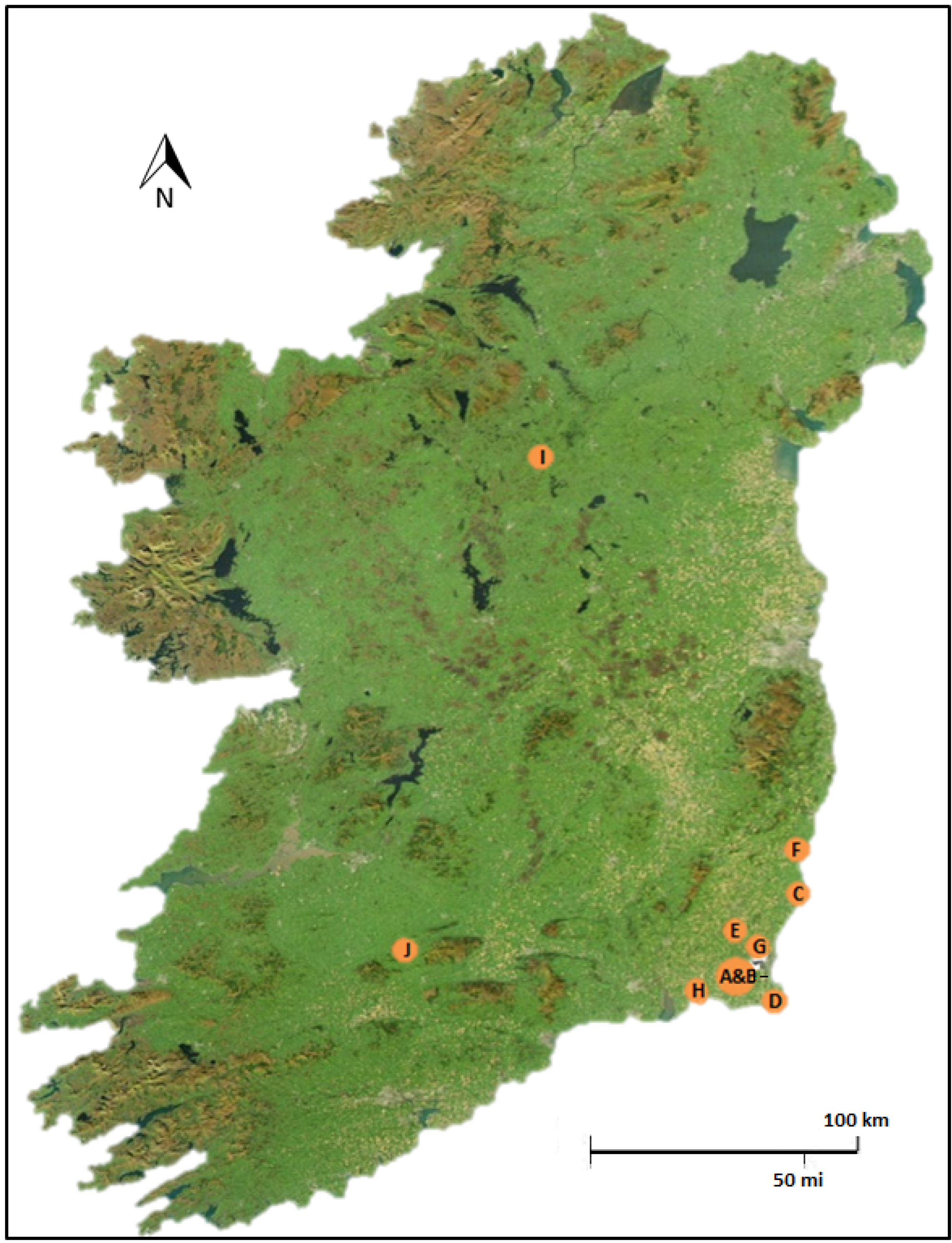
Thirteen full scale willow systems on 10 sites were constructed to treat domestic wastewater effluent from single house dwellings across Ireland: 10 in County Wexford, 1 in County Limerick and 2 in County Leitrim, as shown on Figure 1. The sites were located in areas with very low permeability (i.e., clayey) subsoils, in which effluent percolation would not be a feasible disposal method for the on-site effluent. The systems were designed to specifications that would allow for the long-term study and comparison of key parameters (effluent type, willow species, plan area, aspect ratio and effluent distribution) as detailed in Table 1. The systems were designed (area and depth) based upon a modeled water balance between the typical wastewater effluent rates expected from the dwelling, the local rainfall and the estimated evapotranspiration from the basin over a four year period. Realistic time-varying fluctuations in flows (from basis of previous research carried out by Gill et al. [15]), local meteorological conditions and estimated crop coefficients were input into the water balance model which then simulated willow evapotranspiration across a four year period. The crop coefficients were assumed to be 1 throughout the winter months, increasing up to maximum values of 2.65 across the summer months. At each time step, the calculated stored volume was then divided by the porosity of the soil expected within each willow system (estimated at 30%) to determine the depth fluctuations. Different combinations of area and depth were compared in order to determine the design dimensions of each system which should (theoretically) ensure zero discharge across the 4 year simulation period. The choice of depth was also guided by previous Scandinavian experience with such ET systems using the same willow varieties [7].
Figure 1.
The location of the 13 full-scale ET systems researched in Ireland.

The basins were excavated to a depth of 1.8 m with a geosynthetic barrier laid along the bottom and sides of the excavated basin. An impermeable membrane (minimum 0.5 mm thickness butyl rubber or sealed low-density polyethylene (LDPE) was then laid on top of the geosynthetic barrier followed by a second geosynthetic barrier laid on top of the impermeable membrane. For most systems, the effluent was distributed either by pumping or gravity flow into 110 m rigid diameter pipes at 4 m spacing along the base of the basins bedded in 300 mm depth of 8–32 mm diameter gravel. The excavated soil was then back-filled into the basins up to ground level. On Sites A and B however, the effluent was pumped on a volume-dose basis into a semi-rigid 40 mm diameter distribution pipe at 1 m depth. It should be noted that the excavated soil was used to re-fill the systems due to economic considerations. Importing such a quantity of material would also require more than 50 truckloads of imported earth for a single house which was deemed to be unacceptable for a single house, both logistically and environmentally.

| Site | Constructed | Effluent a | Area (m2) | Aspect Ratio (length:width) | Distribution | Willow Variety |
|---|---|---|---|---|---|---|
| A | May 2009 | STE | 296 | 4.6:1 | pumped | Bjorn, Tora, Jorr |
| B | May 2009 | STE | 570 | 1.6:1 | pumped | Bjorn, Tora, Jorr |
| C | April 2010 | STE | 420 | 2.9:1 | pumped | Tora, Torhild, Tordis |
| D | May 2010 | STE | 464 | 1.8:1 | gravity | Tora, Torhild, Olof |
| E | April 2010 | STE | 24 | 2.7:1 | gravity | native Irish species |
| F(1) | July 2010 | SE | 900 | 1.4:1 | gravity | Tora, Tordis, Olof |
| F(2) | July 2010 | SE | 900 | 9.0:1 | gravity | Tora, Tordis, Olof |
| G | September 2010 | SE | 340 | 3.4:1 | gravity | Tora, Tordis, Olof |
| H(1) | April 2011 | STE | 260 | 4.1:1 | pumped | Tora, Tordis, Inger |
| H(2) | April 2011 | STE | 260 | 4.1:1 | pumped | Tora, Tordis, Inger |
| I(1) | May 2011 | SE | 216 | 3.4:1 | gravity | Tora, Torhild, Olof |
| I(2) | May 2011 | SE | 216 | 3.4:1 | gravity | Tora, Tordis, Torhild |
| J | May 2012 | STE | 170 | 6.8:1 | pumped | Tora, Torhild, Tordis |
Notes: a STE—septic tank effluent; SE—secondary treated effluent.
Willow cuttings (see Table 1 for varieties) were planted at a density of 3 per m2. Coppicing of all the willows was then carried out, in accordance with standard short rotation coppice guidelines [16,17] whereby all shoots were cut back as close to the ground as practically possible in the first dormant season to encourage vigorous growth and multiple shoot development in the following season. Cutback was carried out in a three year cycle thereafter, with alternating thirds of the willow system cut every year.
2.2. Instrumentation
Each ET system was designed in order to quantify the hydraulic loading via rainfall and effluent from which a water balance calculation was used to determine the removal of water from the system via evapotranspiration. A tipping bucket device was used to measure flow continuously on the sites that had a sufficient slope for a gravity feed from the proprietary system to the willow system (as well as splitting the flows evenly between systems on sites with two willow systems). A reed switch on the tipping bucket was connected to a Solinist® Rainlogger Model 3002 (Georgetown, ON, Canada) datalogger. On sites where pumping of effluent to the willow system was required, OTT Thalimedes (Kempten, Germany) water level meters (accuracy: ±0.002 m) were installed in the sump to measure continually the water level. The water level within each ET system was measured on an hourly basis using an OTT Orpheus Mini groundwater datalogger (accuracy: ±0.05%). Campbell Scientific (Loughborough, UK) weather stations were installed to record temperature, relative humidity, wind speed, solar radiation and net radiation. Campbell Scientific ARG100 tipping bucket rain gauges were installed on all sites and either connected to the Campbell Scientific dataloggers or to Solinist® Rainlogger (Model 3002) dataloggers.
2.3. Water Quality Analysis
All septic tank effluent (STE), secondary treated effluent (SE), samples of stored water within each system (taken from the inspection wells) and ponded surface water were periodically analysed for chemical oxygen demand (COD), total nitrogen (TN), ammonium (NH4+–N), nitrite (NO2−–N), nitrate (NO3−–N), orthophosphate (PO43−–P), chloride (Cl−) and sulphate (SO42−) using a Merck Spectroquant Nova 60® spectrophotometer (Darmstadt, Germany). In addition, indicator bacteria of faecal contamination, Total Coliforms (TC) and E. coli were analysed for using the IDEXX Colilert®-18 test (Westbrook, MA, USA) with enumeration carried out using IDEXX Quanti-Tray®/2000, a semi-automated quantification method based on the Standard Methods Most Probable Number (MPN) model.
2.4. Soil Porosity
In order to calculate the water balance accurately, the available pore space in the soil within the willow ET system needed to be calculated from which the depth of effluent in the system could be converted into a stored volume. Replicate 200 mm deep soil samples were collected in 100 mm diameter steel cores at a variety of depths from within the ET systems on each site at the end of the growing season when the water levels within the willow systems were low. The samples were transported back to the laboratory and extruded and then weighed immediately to represent the weight of a fully drained (in situ) sample. The sample length was then submerged in water until saturation point was reached. Upon removal, the soil sample was then reweighed to determine the water content at the saturation point. In addition, the resultant change in water level within each ET system in response to single peak, short duration, large rainfall events were analysed from the field data. Such short rainfall events were used to minimise the effect that any ongoing evapotranspiration would have on the water level. Knowing the net rainfall falling onto the system and respective rise in water level, the effective porosity (usable storage volume) could be calculated and then averaged out for a series of events. It should be noted that the effective porosity of any gravel in the system was also included in the depth-volume calculations when appropriate, using a measured gravel porosity of 32%.
3. Results from the Field Trials
3.1. Loadings
A summary of the data collected at each site is shown in Table 2 with examples of rainfall and potential ET (ETo) from 2013. A more detailed discussion of the field results is discussed in Curneen and Gill [18].
| Site | Effluent Production Started | Population Equivalent (PE) | Mean Daily Flow (L/d) | Effective Soil Porosity (%) | Annual Rainfall (2013) (mm) | Annual ETo (2013) (mm) |
|---|---|---|---|---|---|---|
| A | October 2010 | 4 | 628.4 a | 15.1 | 981 | 585 |
| B | January 2012 | 1 | 443.1 a | 15.6 | 981 | 585 |
| C | December 2010 | 2 | 356.7 | 11.0 | 933 | 584 |
| D | May 2010 | 4 | 483.3 | 11.0 | 847 | 592 |
| E | April 2011 | n/a b | 3.0 | 21.0 | 833 | 571 |
| F(1) | January 2013 | 3 | 306.6 | 18.0 | 811 | 587 |
| F(2) | January 2013 | 3 | 306.6 | 19.0 | 811 | 587 |
| G | n/a b | 0 | 0 | 9.6 | 928 | 610 |
| H(1) | March 2012 | 2 | 181.3 | 9.5 | 930 | 602 |
| H(2) | March 2012 | 2 | 181.3 | 9.5 | 930 | 602 |
| I(1) | November 2012 | 2 | 163.4 | 16.0 | 1158 | 465 |
| I(2) | November 2012 | 2 | 163.4 | 20.0 | 1158 | 465 |
| J | November 2012 | 3 | 330.3 | 19.0 | 1039 | 526 |
Notes: a suspected rainwater infiltration into effluent; b an ET system was constructed for a new house but no-one moved into the house during the monitoring period.
3.2. Water Level Fluctuations
Although all the willow ET systems had been designed to operate as zero discharge systems on the basis of a theoretical water balance, the water level data (as well as observations at the sites) revealed that no system managed to achieve zero discharge in any year, remaining full for much of the winter months. This indicated ongoing loss of water by lateral exfiltration at the surface during these winter periods. Overflows did also occur to a certain extent during the summer of 2012 when precipitation levels were exceptionally high.
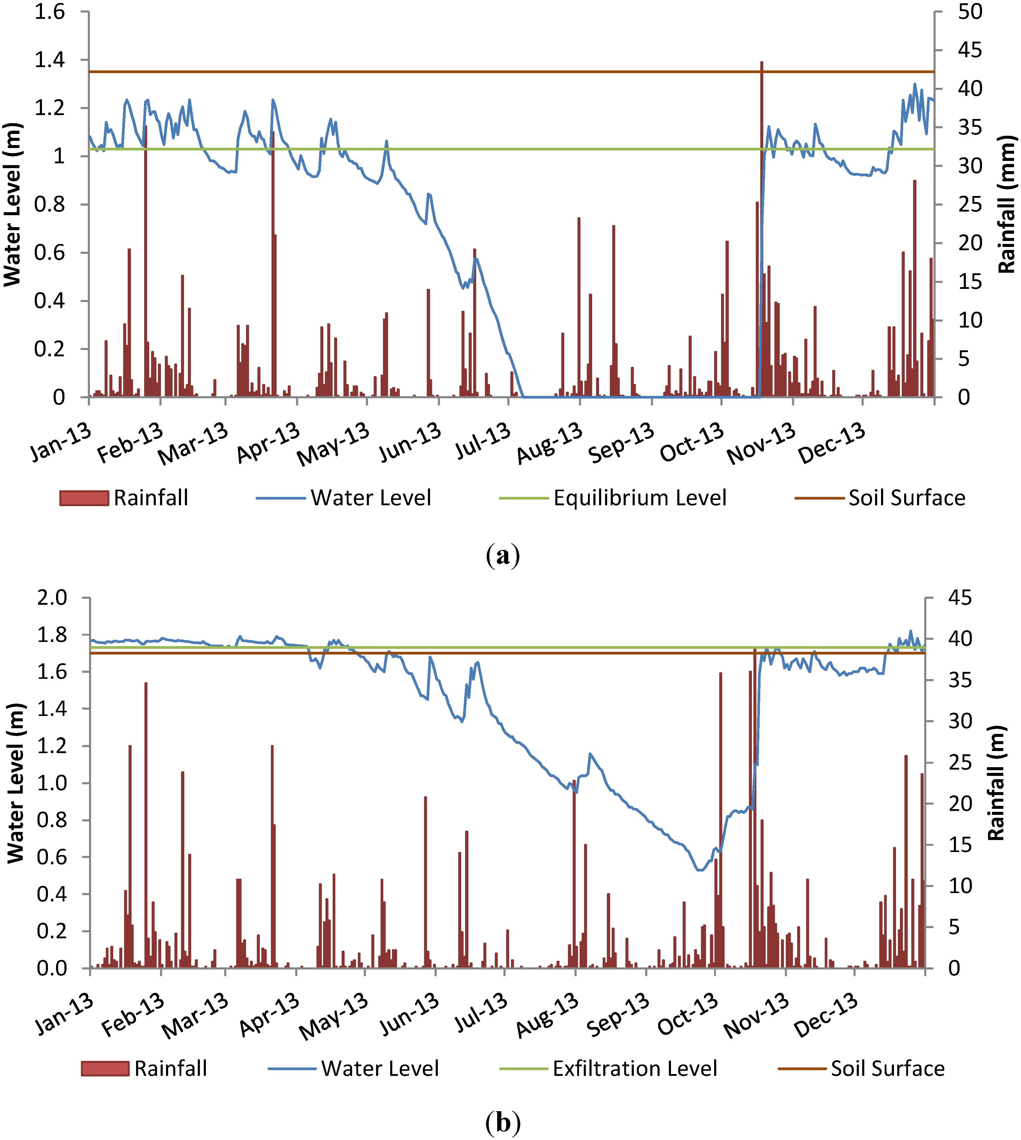
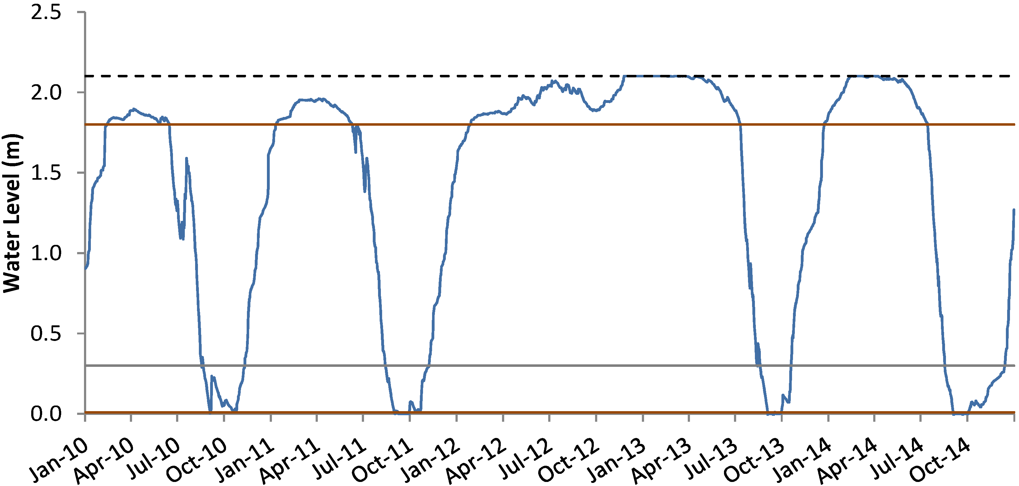
An example of annual water level profiles within two willow systems is shown in Figure 2. The equilibrium level (the level above which overflow from the system occurs) along with the soil surface level are illustrated, both of which are measured relative to the base of the system. For example, at Site A (Figure 2a) overflow was determined to be occurring at a depth of 1.02 m even though the soil surface level was 1.35 m, suggesting that either the impermeable liner did not reach up to the top of the system or it had been breached at this depth. It can also be observed that the system was empty for most of the summer months, meaning that optimal evapotranspiration performance was probably not achieved during that period. This did not occur at Site C (Figure 2b), primarily due to the system being much deeper with an overflow level at 1.73 m from the base. It is also interesting to note the effect of large October rainfall events on the water level in the systems, in response to which both systems refilled to capacity in a very short space of time, which is indicative of the low effective soil porosities.
Figure 2.
Water level and daily rainfall (2013) for (a) Site A; (b) Site C.

3.3. Water Balance (ET and Crop Factors)
The actual evapotranspiration from each system throughout the monitoring period was determined on the basis of a water balance taking into account the measured hydraulic loadings from rainfall and wastewater, as shown in Equation (1):
where, ETwillow = evapotranspiration from willow system; R = rainfall; I = influent (wastewater); ΔH = change in water level within system; Vu = usable water volume storage within soil/gravel (i.e., effective porosity); A = surface area.
Evapotranspiration rates attained by the willow systems were calculated on a daily basis with the results then averaged and presented on a monthly basis. At such times when the water level was above the overflow point, ETwillow could not be accurately calculated using water balance Equation (1), as the volume of water leaving the system due to any exfiltration/overflow could not be quantified. Hence, for such flooded periods during the growing season, mean daily ET rates for those days were assumed to be the same as the closest days during which ETwillow rates could be rigorously calculated using Equation (1). In the winter months when the trees were dormant, it was assumed that ETwillow was equal to ETo on days where the water level was above the overflow level: on all other days, the actual ETwillow was calculated according to Equation (1). Monthly crop coefficients (Kc) were calculated by dividing the assumed monthly ETwillow by the ETo for the month.
The total assumed ETwillow for the monitored period in each calendar year for each willow system shown in Table 3 reveals significant variation between the willow systems, even for those systems in which the willow cuttings had been planted in the same year. Several reasons are thought to attribute to this including different effluent loadings, different soil porosities and different rates of establishment/development of the willow trees. The highest ETwillow rates were calculated for Sites A, B, C, and F(2), which was expected as these sites undoubtedly had better willow tree development (also aided by effluent loading from the outset for Sites A and C).
| System | 2010 | 2011 | 2012 | 2013 | 2014 | |||||
|---|---|---|---|---|---|---|---|---|---|---|
| ETwillow | months | ETwillow | months | ETwillow | months | ETwillow | months | ETwillow | months | |
| A | 755 | 10 | 929 | 12 | 725 | 12 | 928 | 12 | - | - |
| B | 554 | 7 | 638 | 12 | 765 | 12 | 723 | 12 | - | - |
| C | 358 | 4 | 717 | 12 | 670 | 12 | 752 | 12 | 845 | 12 |
| D | - | - | 558 | 12 | 495 | 12 | 487 | 12 | - | - |
| E | 282 | 7 | 573 | 12 | 669 | 12 | 90 | 4 | - | - |
| F(1) | - | - | 511 | 10 | 595 | 12 | 577 | 12 | 598 | 12 |
| F(2) | - | - | 641 | 10 | 827 | 12 | 817 | 12 | 930 | 12 |
| G | - | - | 341 | 7 | 574 | 12 | 445 | 8 | - | - |
| H(1) | - | - | - | - | 864 | 9 | 788 | 12 | - | - |
| H(2) | - | - | - | - | 771 | 9 | 576 | 12 | - | - |
| I(1) | - | - | - | - | 424 | 9 | 613 | 12 | - | - |
| I(2) | - | - | - | - | 402 | 9 | 540 | 12 | - | - |
| J | - | - | - | - | - | - | 680 | 12 | - | - |
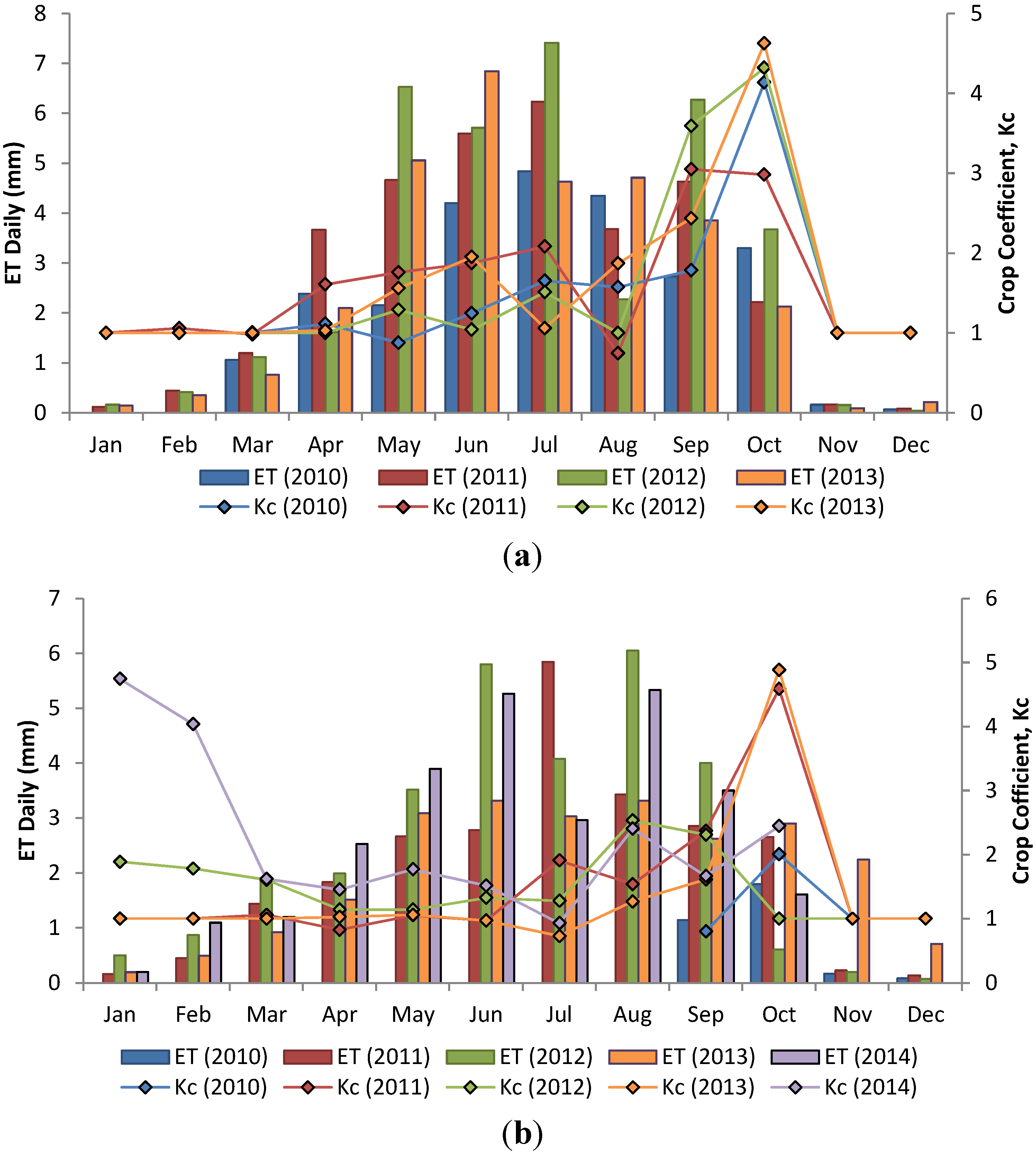
Typical ETwillow results and crop coefficients from two of the longest operating systems (Site A and Site C) are shown in Figure 3. As expected, the highest ETwillow rates were attained in the summer months during the willow trees’ growing season. It might have been expected that the ETwillow rates would increase year on year, as the willow trees developed and became larger. However, the mean daily ETwillow for each month on Site A shows that this was not always the case. While the mean daily ETwillow did increase year on year from 2010 to 2012 for the months May, June, July and September, it decreased for all these months (except June) in 2013. This is probably due to the low water availability within the system at these periods, thus preventing the willows from being able to attain their optimum potential evapotranspiration, and possibly an indication that the roots had not developed down to the base of the system.
Figure 3.
Monthly average ETwillow rates for (a) Site A and (b) Site C.

A comparison of the crop coefficients also shows a similar result. Most of the monthly ETwillow highs (as well as associated crop coefficients) throughout the growing season occurred in 2012 when water availability was at its highest due to the high rainfall levels, not in 2013 when the willow trees were more developed and reference evapotranspiration rates were higher. It is also interesting to note the relatively high crop coefficients in September and October, which shows that there was still a significant amount of water being evapotranspired even though the ETo values were relatively low.
3.4. Water Quality
The quality of the effluent discharged into the systems, the water in each system’s monitoring well and ponded water on the surface during winter is shown in Table 4. An interesting comparison can be made between the water quality in the sumps from those systems that were receiving effluent and those monitored before effluent was introduced. As would be expected, the nutrient concentrations were marginally higher in the samples from the systems receiving effluent compared to the samples from the systems with no effluent. However, the results show that the willow systems acted as an excellent pollutant attenuation process on the influent, promoting greatly reduced organic, nutrient and indicator bacteria concentrations. Equally, the quality of standing water during winter periods on top of the systems receiving effluent proved similar to the sump samples from the systems that had not received effluent, with the exception of very low levels of indicator bacteria.
| water quality parameter | STE | ET Systems Receiving Effluent | ET Systems with No Effluent | |
|---|---|---|---|---|
| ET System Sump | Ponded Water on Surface | ET System Sump | ||
| COD (mg/L) | 377 ± 96 | 42.6 ± 8.9 | 29.8 ± 6.7 | 32.9 ± 7.1 |
| Total-N (mg/L) | 50.3 ± 8.7 | 9.8 ± 2 | 12.4 ± 4.1 | 8.1 ± 1.4 |
| Ortho-P (mg/L) | 6.3 ± 1.2 | 0.55 ± 0.4 | 0.24 ± 0.14 | 0.30 ± 0.08 |
| E. coli no./100 mL * | 9.2 × 10⁵ | 22.1 | 8.3 | <1 |
Note: * geometric mean.
4. Evaluation of Design Parameters on Performance
4.1. Model to Simulate ET System Performance
In order to use the results of the field trials to develop appropriate national design guidelines, modelling was first carried out to predict the effect of varying the different design parameters using realistic crop factors and meteorological data as determined on site from the field trials. The design model for sizing of a willow system was based on a daily water balance (i.e., Equation (1)) which incorporated hydraulic loading into the system via rainfall and effluent and removal of water from the system via evapotranspiration. Daily rainfall and reference evapotranspiration measured on Sites A and B over the duration of the monitoring period was used as inputs into the model to produce the resultant daily water level profiles over a five-year monitored period (January 2010–December 2014).
The usable effective porosities used in the model varied according to the medium at and below any particular water level, as shown schematically on Figure 4: changes in water level occurring within the soil medium assumed a Vu value of 15%; changes within the gravel layer used a Vu of 33%; and changes in water level above the surface of the soil assumed Vu to be 100%.
Figure 4.
Sample cross-section of ET system with relevant effective porosities (Vu).

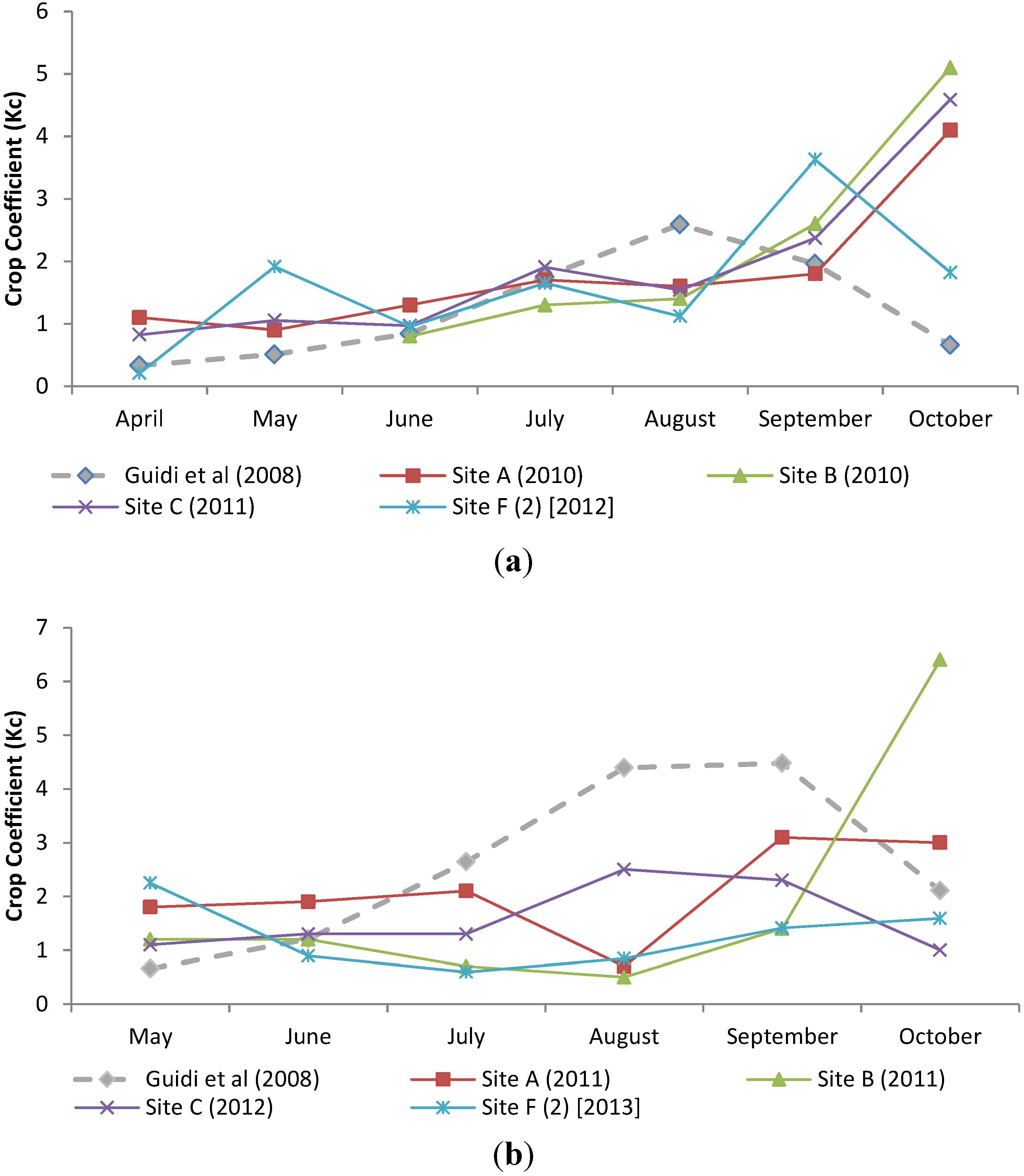
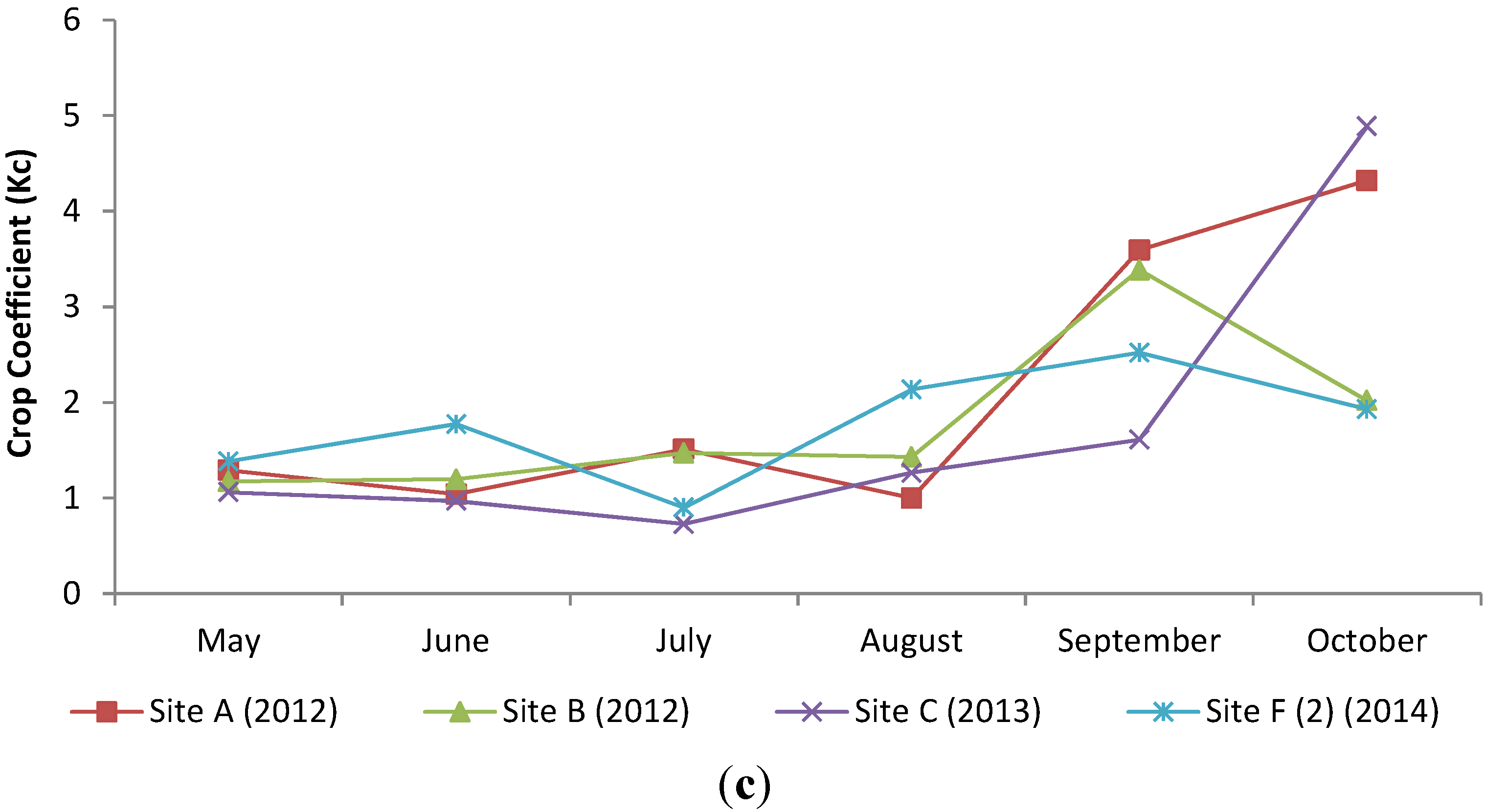
The ET rates and crop coefficients (Kc) used were based on the results from the systems at Sites A, B, C and F(2) which were deemed to have performed to the expected standard over the duration of the research project as they had not been compromised by poor growth or low effluent loading as many of the other sites had. For Sites A and B, it was considered that conservatively low crop coefficients were calculated across some of the summer months due to the fact that the systems had emptied out quite early in two of the monitored growing seasons, leaving little water readily available for evapotranspiration. This is illustrated in Figure 5 which shows a comparison between the crop coefficients for the two systems with those determined in irrigated lysimeter experiments carried out by Guidi et al. [19] for willows in the first and second growing seasons: the crop coefficients on Sites A and B were equal to or higher than the lysimeter experiments for May and June but then dropped back for the rest of the summer months when the systems were empty. As such, it was deemed that these crop coefficients were lower than values that could be expected had water been more readily available if the systems had been deeper. Hence, the representative Kc values used for the model shown in Table 5 were chosen based the crop coefficients determined in the field trials but also influenced by the higher values determined by Guidi et al. [19] in August. The dormant season crop coefficients were determined by taking the average values from all systems as the results showed that willow development appeared to have a minimal bearing on these values. The annual crop coefficient used to model the ET systems works out at 2.2 which, for a mean annual ETo on Sites A and B of 517 mm across the monitoring period, would give an expected annual total of 1135 mm of evapotranspiration from the modelled system.
Figure 5.
Crop coefficients for Sites A, B, C and F(2) compared to those determined by Guidi et al. [18] for (a) first growing season; (b) second growing season and (c) third growing season.
Figure 5.
Crop coefficients for Sites A, B, C and F(2) compared to those determined by Guidi et al. [18] for (a) first growing season; (b) second growing season and (c) third growing season.


| Month | Assumed Kc | Mean ETo (mm) | ETwillow (mm) |
|---|---|---|---|
| January | 1.5 | 4.4 | 9.1 |
| February | 1.4 | 11.0 | 20.8 |
| March | 1.4 | 32.1 | 48.0 |
| April | 1.3 | 59.2 | 77.0 |
| May | 1.5 | 82.2 | 123.4 |
| June | 1.9 | 92.1 | 175.0 |
| July | 2.1 | 84.4 | 177.2 |
| August | 3.4 | 76.7 | 260.9 |
| September | 3.6 | 46.7 | 168.1 |
| October | 3.2 | 20.9 | 66.8 |
| November | 1.4 | 4.9 | 6.8 |
| December | 1.2 | 1.9 | 2.3 |
| Annual Mean | 2.2 | 516.6 | 1135.4 |
4.2. Comparison of Design Parameters
The ETwillow water balance model was then used to predict the water level profile response of the system to various different physical design factors: the plan area of system, the effective porosity of the storage medium (soil and gravel), the depth of soil within the willow system basin, the depth of gravel layer within the system and the depth of free space available above soil surface (maintained by a raised boundary (bund)). For each simulation, the five years of rainfall and reference evapotranspiration data from the field trials (2010 to 2015) were used as inputs. The model then simulated the expected water level profile and any predicted overflow for any defined wastewater loading. Various combinations (within practical constraints) of the above factors were used in order to determine the minimum area required to try to reduce any runoff from the systems as much as possible throughout the year. The model showed that the evapotranspiration that could be expected from a willow ET system in a given year in Ireland’s climate would generally be lower than the corresponding hydraulic load (rainfall and effluent), resulting in overflow from the system occurring, as was the case in 2012. This mirrored the findings on most of the systems monitored. Hence, simulations were carried out to seek to optimise the system in terms of lowering the amount of overflow days that may occur, while also taking practical area and financial constraints into account.
4.2.1. Plan Area and Overall Depth
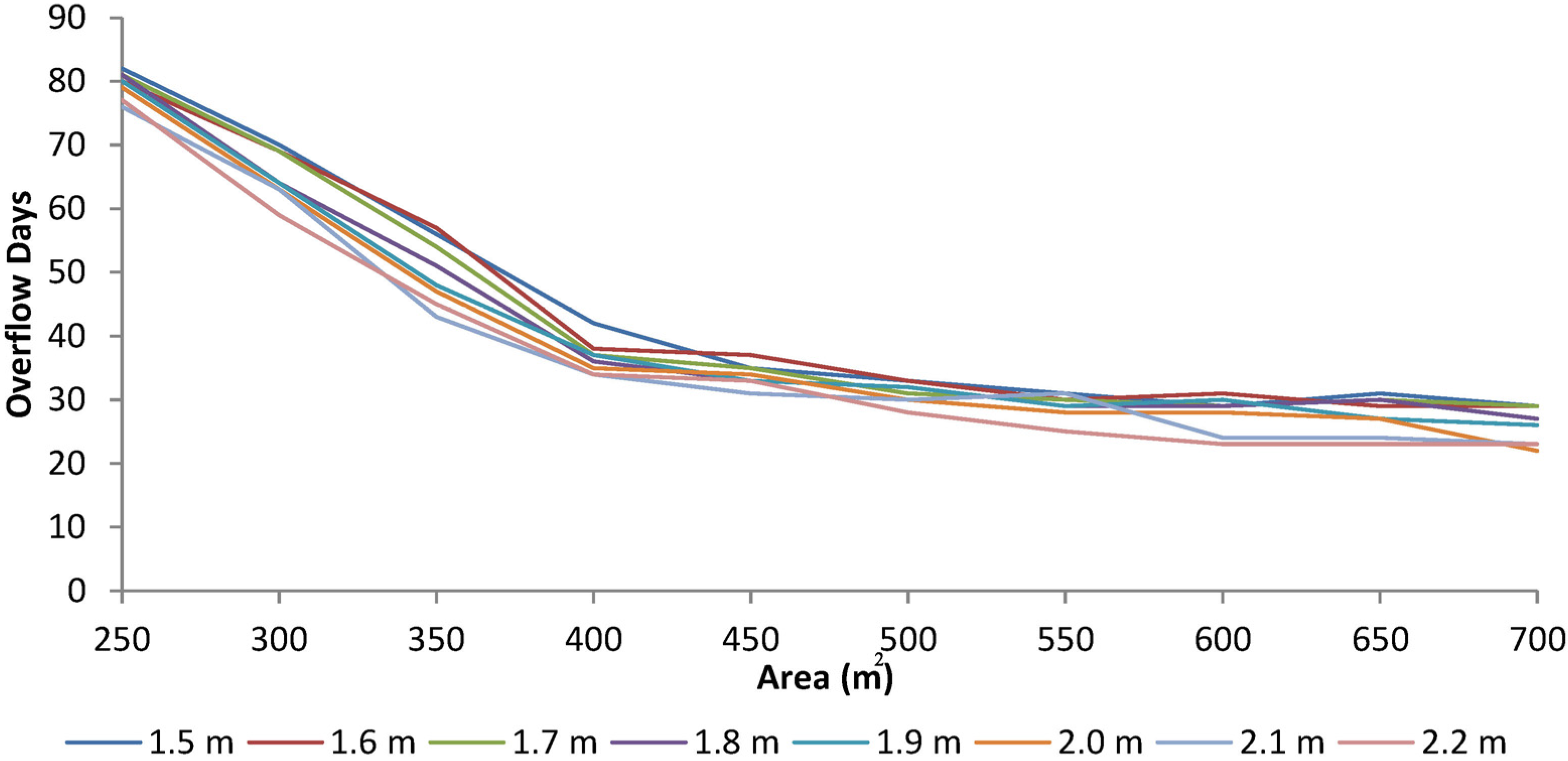
The effect of plan area and overall system depth on water level depth was examined using simulations based on a dwelling with a population equivalent (PE) of 4 with the other design parameters listed in Table 6, fixed. The effect of increasing the area on the number of overflow days is illustrated in Figure 6 which shows that significant gains with respect to decreasing the amount of overflow days can be made by increasing the plan area of the ET system from 250 up to 500 m2. However, any further gains made by increasing the surface area beyond 500 m2 appear to be marginal and would probably not justify the significant additional construction costs required.
| Area (m2) | Effluent (L/c.day)* | Soil Porosity (%) | Gravel Porosity (%) | Depth of Gravel Layer (m) | Depth to Soil Surface (m) | Depth of Free Space (m) |
|---|---|---|---|---|---|---|
| 500 | 100 | 15 | 35 | 0.3 | 1.8 | 0.3 |
Note: * litres per capita per day
Figure 6.
Effect of plan area on the mean number of overflow days simulated per year.

An example of a water level profile produced by the model for a 500 m2 plan area system for a 4 PE residence is shown in Figure 7. The system was determined to have overflow for 141 days across the five-year period corresponding to the monitoring of the full-scale systems. It is worth noting that water level would be predicted to reach the bottom of the system by the end of August in four out of five of the growing seasons monitored.
Figure 7.
Water level profile simulated by the water balance model for a 500 m2 ET system receiving effluent from a 4 PE house.
Figure 7.
Water level profile simulated by the water balance model for a 500 m2 ET system receiving effluent from a 4 PE house.

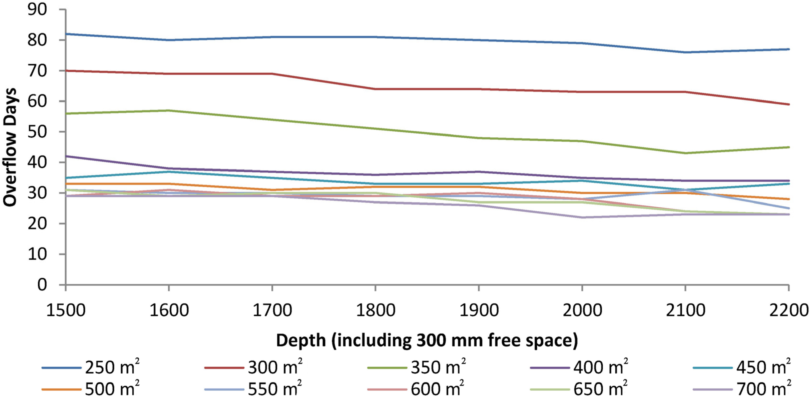
The effect of increasing the overall depth on the amount of overflow from the willow system in Figure 8 shows that it would be beneficial for smaller areas (<350 m2) and to a lesser extent for larger areas (>550 m2). For the range of areas in between, however, it appears that not much benefit can be gained by increasing the depth of the system.
Figure 8.
Effect of increasing the depth on the mean number of overflow days simulated per year.

A matrix highlighting the predicted overflows for different combinations of area and depth is illustrated in Table 7. As would be expected, the combinations of higher area and depth result in lower predicted days with overflow. Several combinations result in approximately 30 to 35 days of overflow per year, which is probably the realistic optimal minimum, taking practical and financial constraints into account. The effect on the water level profile of increasing the depth of a 500 m2 willow system from 1.5 to 1.8 m, for example, has a limited effect and the number of overflow days, decreasing from 35 to 33. A further increase in depth of the 500 m2 area system to 2.1 m again has limited effect, with a predicted decrease of just 1 overflow day per year over the duration of the modelled period. The overflow days can be reduced to as low as 22 days per year for a 4 PE dwelling, but this would require a significantly larger system of area 700 m2 and overall depth of 2.0 m, at which point such ET systems for single houses would not be deemed to be financially viable in an Irish context.
Table 7.
Matrix showing the mean number of overflow days simulated per year from the willow system for different area and depth combinations.
| Area | Depth of ET System | |||||||
|---|---|---|---|---|---|---|---|---|
| 1.5 m | 1.6 m | 1.7 m | 1.8 m | 1.9 m | 2.0 m | 2.1 m | 2.2 m | |
| 250 m2 | 82 | 80 | 81 | 81 | 80 | 79 | 76 | 77 |
| 300 m2 | 70 | 69 | 69 | 64 | 64 | 63 | 63 | 59 |
| 350 m2 | 56 | 57 | 54 | 51 | 48 | 47 | 43 | 45 |
| 400 m2 | 42 | 38 | 37 | 36 | 37 | 35 | 34 | 34 |
| 450 m2 | 35 | 37 | 35 | 33 | 33 | 34 | 31 | 33 |
| 500 m2 | 33 | 33 | 31 | 32 | 32 | 30 | 30 | 28 |
| 550 m2 | 31 | 30 | 30 | 29 | 29 | 28 | 31 | 25 |
| 600 m2 | 29 | 31 | 29 | 29 | 30 | 28 | 24 | 23 |
| 650 m2 | 31 | 29 | 30 | 30 | 27 | 27 | 24 | 23 |
| 700 m2 | 29 | 29 | 29 | 27 | 26 | 22 | 22 | 22 |
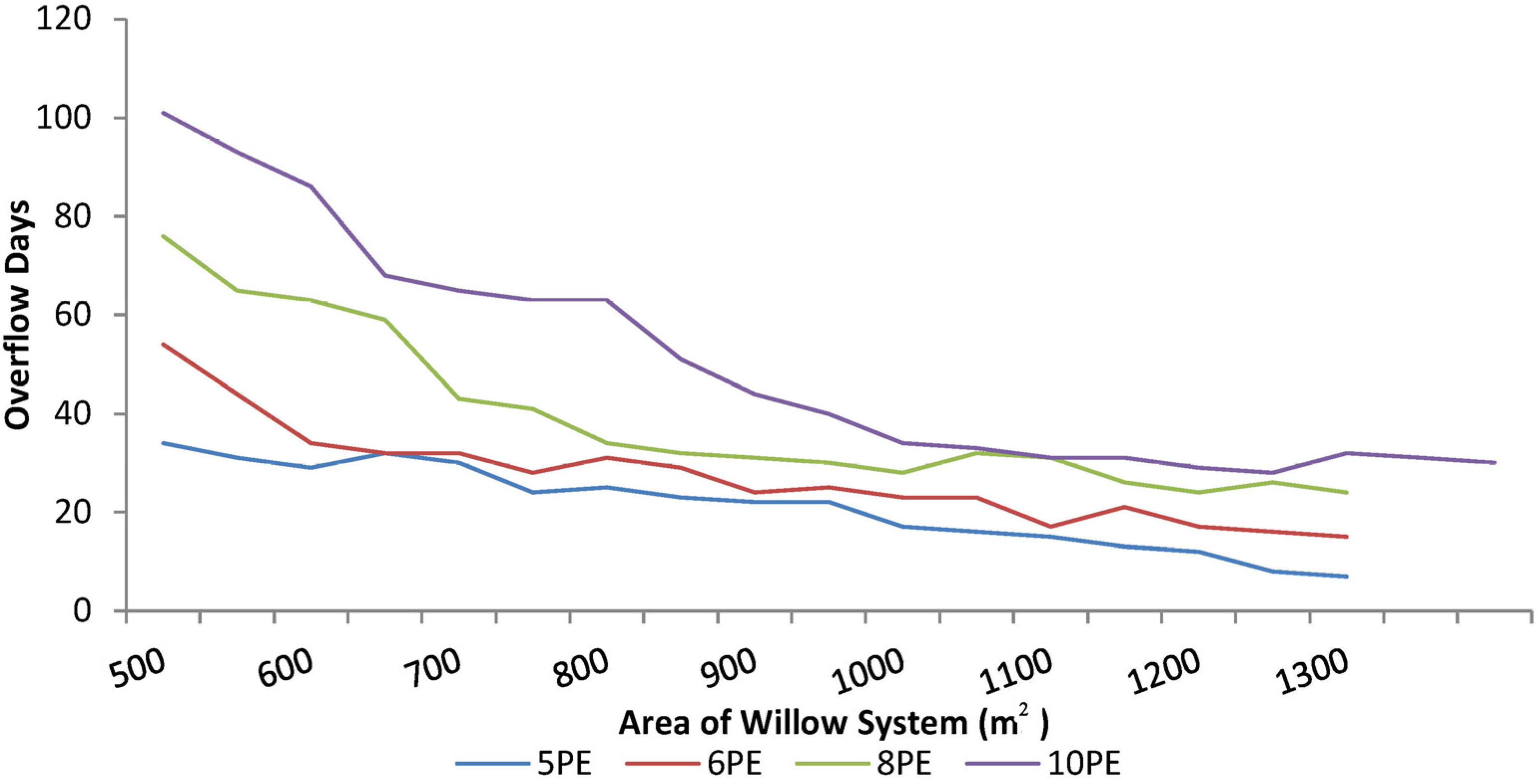
The result of running the model again for four different effluent loadings is shown in Figure 9 and Table 8. The loading rates were 5, 6, 8, and 10 PE, while assuming a daily effluent production of 100 L/c.day. While this effluent loading rate is lower than that assumed in the Irish Code of Practice [4], it is based on the assumption that any dwelling using a willow ET treatment system should have up-to-date water saving appliances (e.g., dual flush toilet, low-flow shower head, tap aerators) whereby such a wastewater production would be realistic.
Figure 9.
Effect of increasing the plan area of the ET system on the mean number of overflow days simulated per year for different hydraulic loading scenarios.
Figure 9.
Effect of increasing the plan area of the ET system on the mean number of overflow days simulated per year for different hydraulic loading scenarios.

Table 8.
Matrix showing the effect of varying the area on the mean number of overflow days simulated per year generated by four different dwelling sizes.
| Area (m2) | 5PE | 6PE | 8PE | 10PE |
|---|---|---|---|---|
| 500 | 34 | 54 | 76 | 101 |
| 550 | 31 | 44 | 65 | 93 |
| 600 | 29 | 34 | 63 | 86 |
| 650 | 32 | 32 | 59 | 68 |
| 700 | 30 | 32 | 43 | 65 |
| 750 | 24 | 28 | 41 | 63 |
| 800 | 25 | 31 | 34 | 63 |
| 850 | 23 | 29 | 32 | 51 |
| 900 | 22 | 24 | 31 | 44 |
| 950 | 22 | 25 | 30 | 40 |
| 1000 | 17 | 23 | 28 | 34 |
| 1050 | 16 | 23 | 32 | 33 |
| 1100 | 15 | 17 | 31 | 31 |
| 1150 | 13 | 21 | 26 | 31 |
| 1200 | 12 | 17 | 24 | 29 |
| 1250 | 8 | 16 | 26 | 28 |
| 1300 | 7 | 15 | 24 | 32 |
| 1350 | - | - | - | 31 |
| 1400 | - | - | - | 30 |
This analysis shows that reductions in the number of overflow days plateau off once a certain area is reached. Lowering the number of overflow days below the 30–35 range requires a significant increase in area, which again would not be considered feasible from a financial point of view. Hence, the practical considered optimum areas for different loadings are shown in Table 9. It should be noted that these areas would give an effluent hydraulic loading of 292 mm per year, based on an effluent production of 100 L/c.day.
| Hydraulic loading | ||||||
|---|---|---|---|---|---|---|
| 2PE | 4PE | 5PE | 6PE | 8PE | 10PE | |
| Optimum Area (m2) | 250 | 500 | 650 | 750 | 1000 | 1200 |
4.2.2. Free Surface Depth to Overflow
The optimum depth of free space above the surface of the soil maintained by a raised bund provides a significant amount of potential hydraulic storage although, ideally, long-term ponding of water on top of the willow system is not desirable. However, the organic and nutrient analysis carried out (see Section 3.4) showed that pollutant concentrations in any surface water were relatively low. Furthermore, no foul odours have been detected on any visits to the sites. The effect of varying the depth of free space on a 500 m2 plan area willow system was conducted by entering a range of depths between 0 and 350 mm (50 mm increments) for three different overall willow system depths (1.5, 1.8, and 2.1 m). Overall depths greater than 2.1 m were not considered because of practical constraints during the excavation phase of construction. The change in the number of overflow days by varying the depth of free space is shown in Table 10.
Table 10.
Effect of varying the depth of free space above the surface of the willow system on the mean number of overflow days simulated per year for three different system depths.
| Depth of Free Space (mm) | Depth of ET System | ||
|---|---|---|---|
| 1.5 m | 1.8 m | 2.1 m | |
| 0 | 76 | 65 | 59 |
| 50 | 72 | 61 | 55 |
| 100 | 62 | 47 | 40 |
| 150 | 58 | 44 | 38 |
| 200 | 42 | 35 | 34 |
| 250 | 37 | 33 | 34 |
| 300 | 33 | 32 | 28 |
| 350 | 30 | 29 | 27 |
Similar to the effect of increasing the area to lower the number of days with overflow, the gains made by increasing the free space appear to be less significant beyond a certain point. The optimum depth of free space in systems with a total depth of 2.1 and 1.8 m is approximately 200 mm (with 34 and 35 overflow days per year respectively), while the optimum depth for a system of depth 1.5 m is 300 mm (33 overflow days).
4.2.3. Hydraulic Load
The benefit of decreasing the hydraulic loading on the system by using an impermeable membrane on the surface of the willow system to direct a proportion of the rainfall away from the basin was also assessed. This analysis assumed that under such a scenario there would be no free storage space available above the soil. As the proportion of rainfall that would be diverted away from the willow system by using an impermeable membrane at the surface is unknown, a hypothetical analysis has been carried out where the rainfall is assumed to be reduced by varying degrees. The model again was based upon a willow system area of 500 m2 receiving effluent from a dwelling with 4 PE with the results of the analysis shown in Table 11. This shows that the ET system could be modified to act as a fully zero-discharge treatment system if 60% or more of the annual rainfall falling onto the system is diverted. However, it should be recognised that the impact of covering the surface of the soil with an impermeable membrane may produce deleterious effects with respect to oxygen transfer down into the soil. This would also reduce soil evaporation.
Table 11.
Matrix showing the mean number of overflow days simulated per year from the willow ET system for different reduced rainfall and depth combinations over a five-year period.
| Rainfall | Depth of ET System | ||||||
|---|---|---|---|---|---|---|---|
| 1.5 m | 1.6 m | 1.7 m | 1.8 m | 1.9 m | 2.0 m | 2.1 m | |
| 100% | 76 | 73 | 68 | 65 | 64 | 62 | 59 |
| 90% | 68 | 64 | 63 | 61 | 58 | 51 | 46 |
| 80% | 58 | 55 | 51 | 43 | 39 | 36 | 34 |
| 70% | 44 | 37 | 33 | 30 | 28 | 25 | 21 |
| 60% | 28 | 24 | 19 | 16 | 13 | 12 | 9 |
| 50% | 16 | 13 | 9 | 8 | 6 | 5 | 4 |
| 40% | 6 | 4 | 3 | 1 | 0 | 0 | 0 |
| 30% | 0 | 0 | 0 | 0 | 0 | 0 | 0 |
| 20% | 0 | 0 | 0 | 0 | 0 | 0 | 0 |
4.2.4. Optimum Design (All Parameters)
In order to further refine the design parameters for an ET willow system, different combinations of plan area, overall depth, depth of gravel layer and depth of free space to overflow were varied to minimise the number of overflow days using the Excel Solver optimisation routine whereby the target parameter to be minimised was the number of overflow days. The constraints for the design parameters were as follows:
- Area (up to a maximum of the value detailed for the corresponding PE in Table 8).
- Depth (up to a maximum overall depth of 2.1 m due to practical constraints)
- Depth of gravel layer (up to a maximum of 350 mm due to cost constraints)
- Depth of free space at the surface (up to a maximum of 300 mm)
The optimum target parameter values (i.e., the smallest values) for different PEs are shown in Table 12. As would be expected, the area required to give the lowest number of overflow days is approximately equal to the maximum area constraint for all cases. The overall optimum depth is also equal to the maximum that the constraint in the model would allow (2.1 m) for all loading rates. There is some variance in the depths of the gravel layer determined for each the different PE, ranging from 279 mm to the maximum of 300 mm. The optimal free space depth above the surface is close to the maximum of 300 mm in all cases.
| PE | Area (m2) | Overall Depth (mm) | Depth of Gravel Layer (mm) | Depth of Free Space (mm) | Overflow Days/yr |
|---|---|---|---|---|---|
| 2 | 250 | 2095 | 300 | 295 | 30 |
| 4 | 498 | 2100 | 285 | 297 | 30 |
| 5 | 646 | 2083 | 279 | 298 | 30 |
| 6 | 750 | 2100 | 300 | 300 | 30 |
| 8 | 991 | 2100 | 295 | 295 | 30 |
| 10 | 1200 | 2100 | 300 | 300 | 31 |
4.2.5. Aspect Ratio
Regression analysis on the field trial results found no conclusive evidence that wind speed had a significant bearing on the ET rate from any willow system (ETwillow) with the exception of the 2011 ETwillow rate on Site B (p-value < 0.05) and the 2013 ETwillow rates on Site A being just outside the 95% confidence interval (p-value = 0.092). Equally, sensitivity analysis, in which the relative effect of the different meteorological parameters on ETo was assessed, revealed that wind speed had a low Spearman Rank-order correlation coefficient with ETo. Analysis also showed that wind speed had a relatively low influence on the ETo: for example, a one standard deviation increase in wind speed would result in an increase of just 0.15 mm ETo, compared to a one standard deviation increase in net radiation which would result in an increase of 1.38 mm ETo. The effect of wind speed has been reported to have a greater effect on ETo for taller crops although such research [20] has shown that the wind speed needs to be relatively high (>6 m/s) before any significant increase on expected crop evapotranspiration is gained. The average wind speed at the sites monitored as part of this research project was between 2 and 3 m/s. Hence, the field study results indicate that the impact of wind speed on ETwillow is not likely to be a critical factor in such a temperate, high humidity climate (such as Ireland’s) and so any benefit derived from tailoring the willow system design to take advantage of wind speed via a large aspect ratio would be modest. However, if space is available on the site, then it is recommended to aim for a high aspect ratio design, as some benefit will be gained from the exposure to higher wind speeds throughout the willow standing.
5. Discussion and Design Criteria
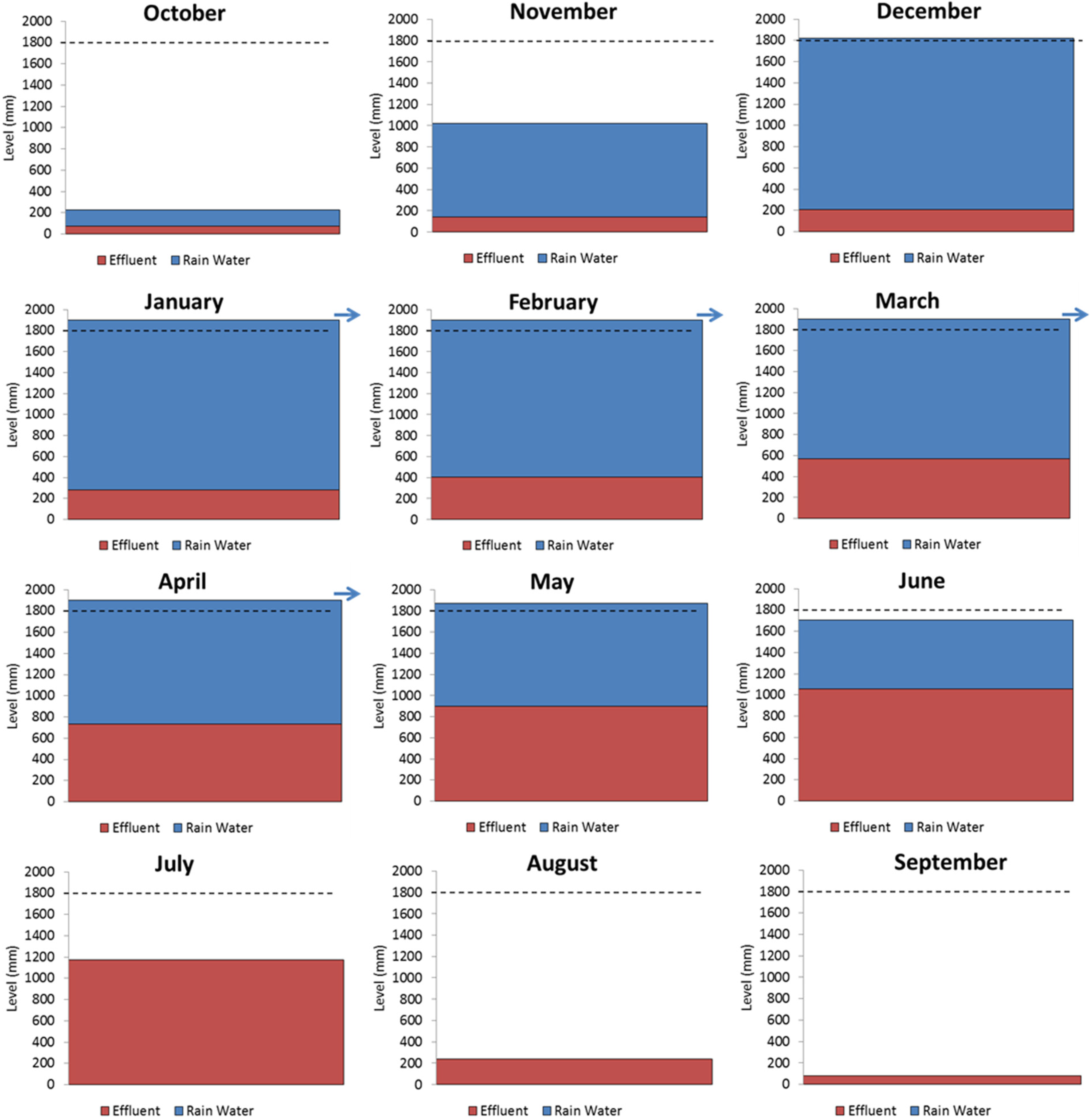
The optimal design dimensions for a willow ET system under different PE loadings (Table 11) indicate that some hydraulic overflow from the sealed systems would be expected during most years due to lower ET levels than the net hydraulic loading from effluent and rainfall. If the wastewater is introduced into the system via distribution pipes in the gravel layer at the base then the effluent will accumulate from the bottom up, compared to the rainwater on the surface which will accumulate from the top down. These hydraulic levels of effluent and rainfall in such an ET system have been simulated on a monthly basis across a hydrological year (i.e., the beginning of October to the end of September) to assess when an overflow would be expected and whether it would consist of primarily rainwater runoff or wastewater, as illustrated in Figure 10. This somewhat simple, yet instructive, analysis assumed that no mixing of effluent and rainwater occurred in the soil within the willow system but also that any water uptake by the willows is preferentially taken from the flooded level downwards (i.e., any ET will preferentially take stored monthly rainfall first before effluent). The depth of the ET system was set at 1.8 m with an overflow at 1.9 m in order to minimise the depth of any standing water and also encourage faster runoff of any rainfall events. The system was designed for a 4 PE residence producing effluent at a rate of 100 L/c.day. The analysis applied a water balance equation using mean annual monthly rainfall and other monitored meteorological data from the weather stations.
The results show that some overflow would be expected from the system during four months of the year (January–April). However, the respective levels of stored effluent from the base and rainfall from the surface indicate that any overflow should be rainwater runoff, which would thus present very little pollution threat to the environment. Indeed, the analysis shows that the majority of the water stored throughout the winter period would be rainwater. From May onwards, the wastewater would begin to make up the majority of stored water, but this would all be contained within the willow system with the maximum depth of wastewater only predicted to reach just over 1 m. It should be noted again that this analysis is based on the conservative assumption that the willow trees would preferentially evapotranspire the rainfall at the top before any deeper wastewater which is unlikely to be the case in reality, as the willow trees would have a preference for the nutrient rich wastewater.
Figure 10.
Expected water levels in willow ET evapotranspiration system across an annual cycle fed with effluent from the base.
Figure 10.
Expected water levels in willow ET evapotranspiration system across an annual cycle fed with effluent from the base.

Hence, this analysis provides a useful insight into the worst-case scenario that could occur and also demonstrates that the system can potentially operate effectively as a zero discharge systems with regards to the effluent loading. It is also important to recognise that this analysis was based upon an effluent production rate of 100 L/c.day (which equates to an aerial hydraulic loading of just less than 300 mm/year). This is similar to the effluent production measured on many of the sites throughout the monitoring period as well as in other research projects in Ireland [15,21] but significantly lower than the 150 L/c.day assumed in the national on-site wastewater Code of Practice [4] for a typical single dwelling. The effect of increasing the effluent loading rate to 150 L/c.day in the simulation is contained in Table 13 where it can be seen that the mean number of overflow days would increase by 60% to 80% for the same area of ET system for any given PE. If such a difference was to be negated by an increase in area, it would require an increase of between 40% and 50%, resulting in a very significant increase in cost.
| PE | Area (m2) | Overflow Days per Year | Area | ||
|---|---|---|---|---|---|
| 100 l/c.day | 150 l/c.day | Increased Area (m2) | % increase | ||
| 2 | 250 | 55 | 85 | 350 | 40% |
| 4 | 500 | 55 | 85 | 675 | 35% |
| 5 | 600 | 51 | 92 | 890 | 48% |
| 6 | 750 | 55 | 85 | 1020 | 36% |
| 8 | 1000 | 55 | 85 | 1350 | 35% |
| 10 | 1200 | 51 | 92 | 1770 | 48% |
Hence, it is imperative that, in such a climate where the expected annual ETwillow is going to be marginally higher than the expected annual rainfall at best, that wastewater production is kept as low as possible. Any design guidelines should include the requirement for modern water-efficient plumbing and appliances to be installed in the dwelling at the time of construction. It is also imperative that the rainfall runoff from the roof of the house is not plumbed into the wastewater system, as this would cause a significant increase in the hydraulic loading of the ET system. This practice appeared to be happening at Sites A and B with the corresponding enhanced hydraulic loads listed in Table 2.
6. Conclusions
A series of full-scale field trials on willow-based ET systems sited in areas of low permeability subsoil has produced data from which realistic ET values from such systems in the temperate, maritime, Irish climate have been gained. The field trials showed that none of the systems were able to evapotranspire all the effluent and rainfall hydraulic loading which were therefore deemed to be losing water by overflow or exfiltration at some times of the year. The effective porosities from the backfilled low porosity soils (i.e., storage space for effluent and rainfall) were also measured on site and found to be much lower than might typically be assumed for soil void ratios, ranging from just 9% to 20%. However, the quality of water stored in the systems, according to samples taken from the inspection wells, indicate that the systems act as very effective passive treatment systems. Furthermore, samples of ponded water on the surface of systems during winter periods have shown that the quality of any potential runoff would be similar to that of water in systems that had never received any effluent.
These field data have then been used to compare the influence of many design parameters on overall ET performance and so develop advice towards the formulation of generic national design guidelines. Realistic dimensions of ET systems for the treatment of wastewater from single houses have been established in order to minimize the numbers of days of any potential overflow. The plan areas of these systems are based on an annual effluent loading of just less than 300 mm per year. Further analysis has shown that if the effluent is fed from the base of the ET system designed to such a specification, this should ensure any overflow during winter periods will be predominantly rainfall runoff and that the net annual wastewater production is effectively fully evapotranspired.
Acknowledgments
The research project was mainly financed by Wexford County Council, Ireland with some additional funding from the Environmental Protection Agency, Ireland. The authors also wish to acknowledge the contribution of Brendan Cooney (Wexford County Council) and Arne Backlund (Backlund ApS) to the research.
Author Contributions
The two co-authors contributed equally to this work. Both authors read and approved the final manuscript.
Conflicts of Interest
The authors declare no conflict of interest.
References
- Central Statistics Office (CSO). Census 2011, Principal Demographic Results; Central Statistics Office, Government of Ireland, Stationery Office: Dublin, Ireland, 2012. [Google Scholar]
- Hynds, P.D.; Misstear, B.D.R.; Gill, L.W. Development of a microbial contamination susceptibility model for private domestic groundwater sources. Water Resour. Res. 2012, 48. [Google Scholar] [CrossRef]
- Environmental Protection Agency (EPA). A Risk-Based Methodology to Assist in the Regulation of Domestic Waste Water Treatment Systems; EPA: Wexford, Ireland, 2013. [Google Scholar]
- Environmental Protection Agency (EPA). Code of Practice: Wastewater Treatment and Disposal Systems Serving Single Houses; EPA: Wexford, Ireland, 2009. [Google Scholar]
- Gregersen, P.; Brix, H. Zero-discharge of nutrients and water in a willow dominated constructed wetland. Water Sci. Technol. 2001, 44, 407–412. [Google Scholar] [PubMed]
- Arias, C.A. Current state of decentralized waste water treatment technology in Denmark. In Proceedings of the EPA International Symposium on Domestic Wastewater Treatment and Disposal Systems, Dublin, Ireland, 10–11 September 2012.
- Miljøstyrelsen. Retningslinier for Etablering af Pileanlæg op til 30 PE. In Økologisk byfornyelse og spildevandsrensning, Nr. 25; Miljøstyrelsen: Copenhagen, Denmark, 2003. (In Danish) [Google Scholar]
- Rosenqvist, H.; Aronsson, P.; Hasselgren, K.; Perttu, K. Economics of using municipal wastewater irrigation of willow coppice crops. Biomass Bioenergy 1997, 12, 1–8. [Google Scholar] [CrossRef]
- Pauliukonis, N.; Shneider, R. Temporal patterns in evapotranspiration from lysimeter with three common wetland plant species in the eastern United States. Aquat. Bot. 2001, 71, 35–46. [Google Scholar] [CrossRef]
- Elowson, S. Willow as a vegetation filter for cleaning of polluted drainage water from agricultural land. Biomass Bioenergy 1999, 16, 281–290. [Google Scholar] [CrossRef]
- Dimitriou, I.; Aronsson, P. Wastewater and sewage sludge application to willows and poplars grown in lysimeters–Plant response and treatment efficiency. Biomass Bioenergy 2011, 35, 161–170. [Google Scholar] [CrossRef]
- Kuzovkina, Y.; Knee, M.; Quigley, M. Soil compaction and flooding effects on the growth of twelve Salix L. species. J. Environ. Hort. 2004, 22, 155–160. [Google Scholar]
- Bialowiec, A.; Wojnowska-Baryla, I.; Agopsowicz, M. The efficiency of evapotranspiration of landfill leachate in the soil-plant system with willow Salix amygadlina. Ecol. Eng. 2007, 30, 356–361. [Google Scholar] [CrossRef]
- Kele, B.; Midmore, D.J.; Harrower, K.; McKenniary, B.J.; Hood, B. An overview of the Central Queensland University self-contained evapotranspiration beds. Water Sci. Technol. 2005, 51, 273–281. [Google Scholar] [PubMed]
- Gill, L.W.; O’Luanaigh, N.; Johnston, P.M.; Misstear, B.D.R.; O’Suilleabhain, C. Nutrient loading on subsoils from on-site wastewater effluent, comparing septic tank and secondary treatment systems. Water Res. 2009, 43, 2739–2749. [Google Scholar] [CrossRef] [PubMed]
- Department for Environment, Food and Rural Affairs (DEFRA). Growing Short Rotation Coppice, Best Practice Guidelines; Defra Publications: London, UK, 2002. [Google Scholar]
- Caslin, B.; Finnan, J.; McCracken, A. Short Rotation Coppice Willow Best Practice Guidelines; Teagasc, Crops Research Centre: Carlow, Ireland, 2010. [Google Scholar]
- Curneen, S.; Gill, L.W. Evapotranspiration Systems using willows for the treatment of on-site wastewater effluent in areas of low permeability subsoils. Ecol. Eng. 2015, in press. [Google Scholar]
- Guidi, W.; Piccioni, E.; Bonari, E. Evapotranspiration and crop coefficient of poplar and willow short-rotation coppice used as vegetation filter. Bioresour. Technol. 2008, 99, 4832–4840. [Google Scholar] [CrossRef] [PubMed]
- Allen, R.G.; Pereira, L.S.; Raes, D.; Smith, M. Crop Evapotranspiration—Guidelines for computing crop water requirements. FAO Irrig. Drain. Paper 1998, 55, 227. [Google Scholar]
- Dubber, D.; Gill, L.W. Application of on-site wastewater treatment in Ireland and perspectives on its sustainability. Sustainability 2014, 6, 1623–1642. [Google Scholar] [CrossRef]
© 2015 by the authors; licensee MDPI, Basel, Switzerland. This article is an open access article distributed under the terms and conditions of the Creative Commons Attribution license (http://creativecommons.org/licenses/by/4.0/).
Share and Cite
MDPI and ACS Style
Curneen, S.; Gill, L. Upflow Evapotranspiration System for the Treatment of On-Site Wastewater Effluent. Water 2015, 7, 2037-2059. https://doi.org/10.3390/w7052037
AMA Style
Curneen S, Gill L. Upflow Evapotranspiration System for the Treatment of On-Site Wastewater Effluent. Water. 2015; 7(5):2037-2059. https://doi.org/10.3390/w7052037
Chicago/Turabian StyleCurneen, Sean, and Laurence Gill. 2015. "Upflow Evapotranspiration System for the Treatment of On-Site Wastewater Effluent" Water 7, no. 5: 2037-2059. https://doi.org/10.3390/w7052037