Article

A Methodology for the Optimization of Flow Rate Injection to Looped Water Distribution Networks through Multiple Pumping Stations

by
Christian León-Celi
1,
Pedro L. Iglesias-Rey
1,*,
F. Javier Martínez-Solano
1 and
Daniel Mora-Melia
2
1
Departamento de Ingeniería Hidráulica y Medio Ambiente, Universitat Politècnica de Valencia, 46022 Valencia, Spain
2
Departamento de Ingeniería y Gestión de la Construcción, Facultad de Ingeniería, Universidad de Talca, 3340000 Curicó, Chile
*
Author to whom correspondence should be addressed.
Water 2016, 8(12), 575; https://doi.org/10.3390/w8120575
Submission received: 16 September 2016 / Revised: 3 November 2016 / Accepted: 23 November 2016 / Published: 6 December 2016

Abstract

:
The optimal function of a water distribution network is reached when the consumer demands are satisfied using the lowest quantity of energy, maintaining the minimal pressure required at the same time. One way to achieve this is through optimization of flow rate injection based on the use of the setpoint curve concept. In order to obtain that, a methodology is proposed. It allows for the assessment of the flow rate and pressure head that each pumping station has to provide for the proper functioning of the network while the minimum power consumption is kept. The methodology can be addressed in two ways: the discrete method and the continuous method. In the first method, a finite set of combinations is evaluated between pumping stations. In the continuous method, the search for the optimal solution is performed using optimization algorithms. In this paper, Hooke–Jeeves and Nelder–Mead algorithms are used. Both the hydraulics and the objective function used by the optimization are solved through EPANET and its Toolkit. Two case studies are evaluated, and the results of the application of the different methods are discussed.

1. Introduction

The growth of urban areas as a result of the increment in population entails that the water resource supply in drinking water networks are insufficient [1]. This is mainly due to the breakdown of pressure head occurring in the network nodes. Increasing water flows entail a greater energy requirement and therefore higher costs at pumping stations. On the other hand, leakage because of aging and infrastructure breaks on networks lead to a growing water demand that increases the energy consumption in order to meet the network requirements [2].
One common counter-measure is to add a new water source using pumps [3]. Undoubtedly, the best way to regulate a water distribution network is to use reservoirs or tanks. That is, all the water supplied from the sources is forced to pass through tanks located at points with enough elevation to ensure minimum pressure in the network. This situation presents significant advantages from an operational point of view: network control becomes easier, and operation strategies are simpler in terms of reducing energy costs. However, it is not always possible to install these tanks or reservoirs. There are networks primarily fed by groundwater, which require heavy pumps to extract water from the supply sources or networks where the land does not have enough elevation to install tanks. In these circumstances, using pumps directly connected to the network is the only mechanism that guarantees supplying water with the minimum pressure requirements.
These pumping stations supply water directly to the water network, so their operating conditions should adapt to the demand flows in every moment. In fact, this solution entails that networks with insufficient flow but potentially operable in an efficient way (in the case of using regulating tanks) become networks with a sufficient flow (adding as many pumps as necessary) but inefficient from an energy point of view.
Hydraulic Institute, Europump, and the Office of Industrial Technologies [4] point out that pumping stations consume around 20% of the world’s energy demand. It is also pointed out that 90% of the whole life cost of a pumping station is due to energy costs [5,6,7]. Thus, any step taken to reduce this consumption is important.
Many works have been developed in order to obtain optimization models of pumping stations [8,9] to achieve a better performance that saves energy and brings down costs. The optimization of the pumping schedule of a water distribution network requires a mathematical formulation for both the characteristic curve of the pumps and the resistant curve of the installation. Vitasovic [10] proposes three equations that describe a pumping system: (a) a pumping curve; (b) an efficiency curve of the pump; and (c) a system curve. The first two curves are proportioned by the manufacturer, and the latter is obtained from the network.
Yin et al. [11] dealt with the reduction of energetic consumption in fixed speed pumping systems by reducing the pump cycles and controlling the frequency of starting and stopping pumps. Later works agree in that a better energetic efficiency is possible through the use of variable speed driven pumps. This is intended to achieve minimum pressure levels and leakages, as well as better control of pumping schedules and of the filling and emptying of tanks [12]. Planells Alandi et al. [13] presented a decision support system based on the number of variable and fixed speed pumps in a pumping station. For the optimum regulation of a pumping system, the pumping operation curve should be adjusted to the height curve of the system (or resistant curve), thus minimizing excess discharge height for each demand [13,14,15,16].
Wu & Gao [2] focused on a multi-objective optimal pump schedule problem with three objectives: the minimization of operation costs including energy costs and treatment costs, the minimization of maintenance related to the number of pump switches, and the maximization of the hydraulic service level.
In pressurized irrigation networks, some measurements have been adopted to optimize energy demand and costs. They include network sectorization, energy audits, pumping station adaptation to a wide range of demand scenarios, and the detection of critical nodes to reach better pressure regulation [17,18,19,20]. However, most of these research works were developed for branch networks with a single water supply point.
Research works by Fernández-García et al. [21,22] focused on the implementation of the above measures for multiple source networks, which is more complex due to the fact that pressure heads in each pumping station have to be estimated at the same time.
Araujo et al. [23] faced the energy saving by means of leakage minimization using valves and establishing their number and location, as well as their opening degree. Nazif et al. [24] address pressure management by regulating the storage level, minimizing leakage at the same time. For that purpose, a genetic algorithm was used.
Recent publications [25,26,27] remark on the benefits of real-time pump scheduling, which permits treatment with short-term demand variations and minimize operation costs. Nevertheless, this is difficult to achieve since a new infrastructure has to be implemented and historical information should be available in order to obtain warm solutions and reduce calculation times.
The present work does not directly address the energy optimization of multiple pumping stations. However, it does aim to obtain a minimum energy curve or setpoint curve for each pumping station. The setpoint curve represents the pressure head required in each water source to deliver a specific flow rate while the minimum pressure at the critical node of the network is guaranteed [28,29].
Moreover, when the pressure is adjusted to a minimum, leakage can be decreased, thereby reducing the water demand and energy consumed. In this work, pressure-dependent consumptions are not considered.
To build the setpoint curve, a search of the optimal flow rates and pressure heads for each pumping station that would reduce energy consumption to a minimum should be performed. Therefore, a nonlinear multidimensional problem with constraints is presented. To solve this problem, it will be split into two levels. In the inferior level, the hydraulics will be settled by EPANET [30], and the superior level is directed to find out the optimal flow rates and pressure heads.
The optimal resolution for this problem can be addressed by discrete or continuous methods. Both options are considered in this work. On the one hand, the discrete methods search for an optimal solution in a finite set of potential solutions. In this work, a finite set of flows and pressure heads to be supplied by each pump station is evaluated in order to determine the best solution.
On the other hand, continuous optimization takes any values permitted by the constraints and leads the search of the optimal solution through optimization algorithms. Nowadays, the use of evolutionary-metaheuristic techniques, such as genetic algorithms, ant colony, and shuffle frogs leaping, among others, is common [31,32,33]. However, due to the short number of dimensions, two direct search methods were applied: Hooke–Jeeves (H-J) [34] and Nelder–Mead (N-M) [35]. Finally, two case studies are presented in order to validate the methodology.

2. Setpoint Curve

Setpoint curve might be defined as a theoretical curve that points out the minimum energy (in terms of pressure head) required on source points (storage, pumping station) to meet the minimum pressure required in each demand in the network, i.e., it is a representation of the pressure head versus the flow at a given point in the system.
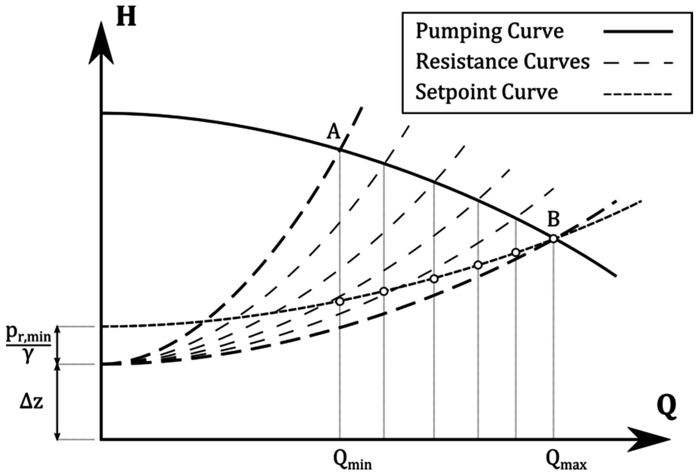
There is one setpoint curve for each supply source. In many cases, the resistance curve is confused with the setpoint curve; nevertheless, they are not the same. To clarify their differences, a simple case has been considered. Thus, in Figure 1, a pump supplying water to a consumer is represented. The consumer can be represented in two different ways: as a demand node (QD) in point D where a minimum pressure pr,min is required, or a resistive element which discharges freely to a particular level. In fact, pr,min is defined as the pressure that is necessary at point D in order to guarantee that the flow through the resistance Rv is the demand QD. These two ways of representing consumption is what is commonly known as time-driven analysis or pressure-driven analysis in water distribution systems analysis.
The definition of the setpoint curve is independent of the system used to supply water from the source: either a pumping system or a reservoir. Both the definition of the setpoint curve and its calculation are exactly the same whether the system is supplied through reservoirs as if the system is supplied by pumps. Provided that the supply system does not affect the calculation of the setpoint curve, this study has focused on the case in which there is a pump in the system.
At some instant, a resistance value Rv,1 has been fixed in the consumer. At that moment, the resistant curve of the installation is the result of adding the difference of levels Δz and the head losses in the system. The intersection of this resistance curve with the pump curve establishes the operating point (P1) and therefore defines the flow Q1 and the pressure head required (H1) at point O in Figure 1. However, if the consumer of Figure 1 demands a flow rate Q1 (Figure 2), the minimum head necessary at point O will be a slightly lower and hence different value (Hc,1).
Mathematically, the head H1 is computed as
H 1 = Δ z + R Q 1 2 + R v Q 1 2
where R is the resistance of the pipeline between the points O and D. Meanwhile, the head Hc,1 is calculated by setting the minimum pressure at point D and considering the required head at point O.
H c , 1 = Δ z + p r , m i n γ + R Q 1 2 .
Therefore, for a certain flow Q1, the values of the minimum head required (Hc,1) and the head (H1) that is finally driven by the supply system (a pump in this case) can be very different. In fact, the closer the value of H1 is to Hc,1, the better the performance of the regulation system.
The efficiency of the control system is based on finding a supply system that provides only the energy required for each flow. However, this work is not focused on the efficiency of the regulation system. The aim of this work was to determine the minimum energy required on each source in order to obtain proper operation of the system. Hence, this energy supplied by each source will be independent of the system used (a pump, several pumps in parallel, a reservoir, etc.).
In a real case, the consumer demand flow varies over time. In other words, the value of the resistance Rv takes different values along the time; therefore, different resistances curves are generated (dashed lines in Figure 2). The consequence of this temporal variation of flow is the appearance of a curve that includes all the minimum head pressure required at the source—the setpoint curve. This curve is completely different from the curve that eventually defines the operating point of the network—the pump curve in this case.
Once the concept of the setpoint curve has been analyzed for a simple case, it is necessary to study how to extend this methodology to the case of a complex water distribution network (WDN). Specifically, it will show how to extend the methodology to calculate the setpoint curve of a system from a particular source of supply. To do this, a hydraulic model representing the behavior of the network is required. This must include the network topology, including demand nodes, pipes, valves, pumps, and sources. In this paper, EPANET [30] has been use as a calculation engine for the hydraulic analysis of the network behavior in different flow scenarios.
The most significant aspect of the hydraulic model, to be useful in determining the curve, is the representation of supply sources. From a real point of view, a flow contribution to the network can be done in two different ways: by an elevated tank or by a pumping system. In this paper, as described above, attention is focused on water supply networks fed by pumping stations. Therefore, each source represents every point immediately downstream the pumping stations necessary to supply water to the network.
Thus, as a general rule, sources are represented as points in which the flow rate to be provided is determined. From this flow, the pressure head required in these points is determined to ensure network operation under the previously defined conditions of the minimum pressure required—in short, as a result of the process flow and pressure head required in each source are obtained. These flow-head values are independent of the pumping station and the regulation system necessary to achieve them. That is, once the flow-head pairs of values required at all times are selected, a pumping station and a control system can be selected in order to meet pressure and flow reference levels.
Therefore, from the viewpoint of the mathematical model, the sources are represented as node injection (negative demand nodes). Representing all sources as injection nodes presents two clear problems for the hydraulic model. First, the sum of the flow rates of all injection nodes was equal to the total flow rate demanded by the network. Second, if all sources are represented as consumption nodes, there cannot be a pressure reference point on the network. In this regard, it should be reminded that, in order to perform network analysis [30], it is always necessary to have at least one pressure node (a reservoir or a tank).
In short, one source is always represented as a reservoir and the rest are represented as injection nodes. In these injection nodes, the flow will be fixed, and the head remains unknown. These heads must be determined in a way that ensures these flows. The source represented as a reservoir do not need to define the injected flow, as it will supply the remaining flow to complete the entire demand. In this reservoir the head will be set up. The head will be modified until the minimum pressure condition in the worst node is guaranteed.
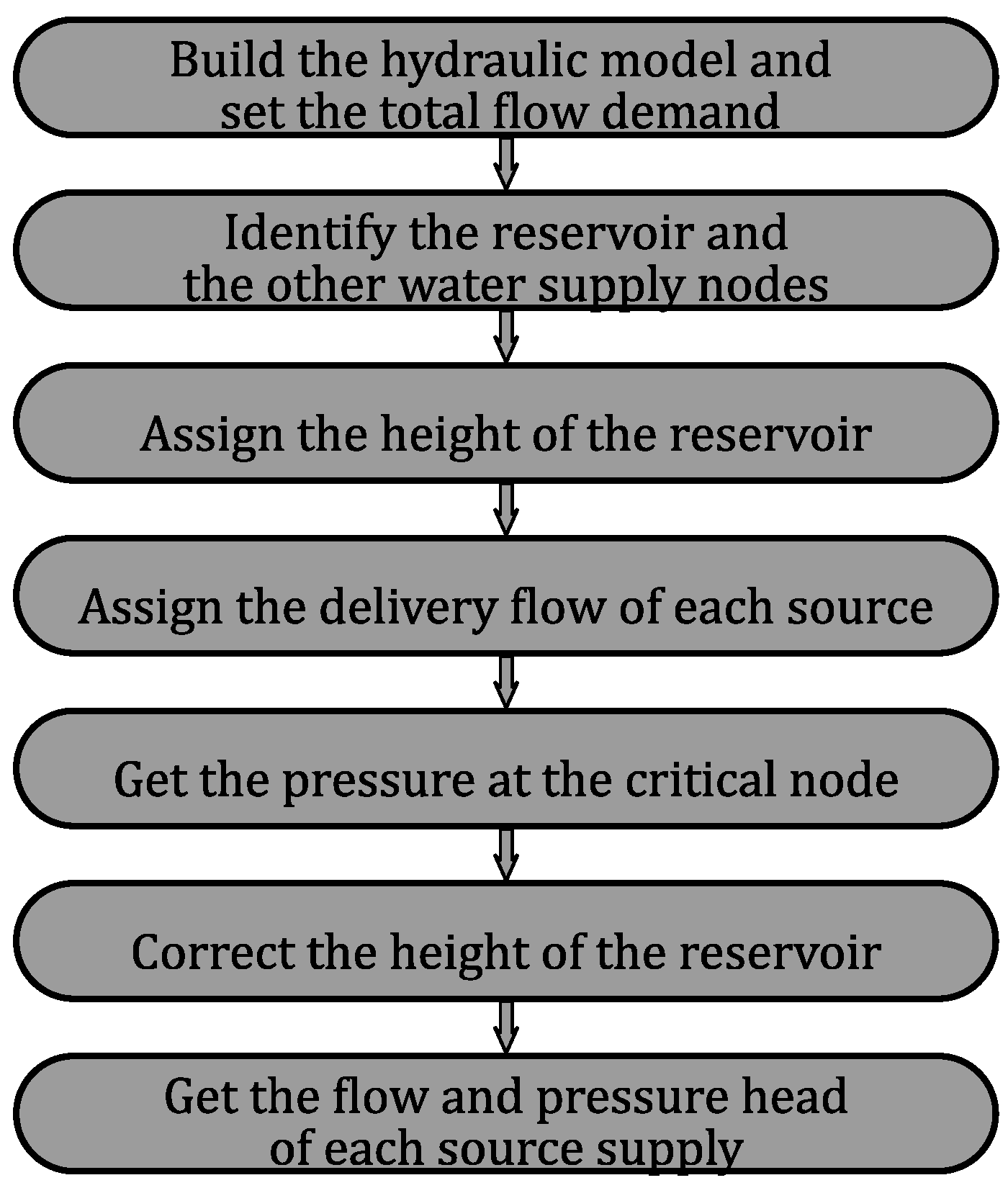
The basic steps to determine the setpoint curve are those collected schematically in Figure 3. The first step is to have a mathematical model of the network and establish a distribution of flow between its demand nodes. The aim is to distribute the total demand between the nodes of the network for any of the demanded flow scenarios. That is, applying the methodology requires performing the same approach that is used when a dynamic model of the network is built [36].
The next step is to set the source that is represented as a reservoir, while the other sources are represented as injection nodes. Then, an arbitrary value is allocated to the head (HR,0) in the sources represented as a reservoir. Thus, for a given stage (j), both the total demand of the network (Qj) and its distribution between the different nodes are known. The flow rate to be supplied (QS,n) by each source (n) is calculated as a fixed proportion (xs) of the total flow demanded (Qj). Mathematically, this relation can be expressed as
Q s n = x S × Q j   n = 1 ,   ... , N s 1 ;   j = 1 ,   ...   ,   N s t .
The above equation can be applied to the sources represented as injection nodes (the number of sources Ns except one) and for the number of stages (Nst). Once the values xs are established, the hydraulic system is solved in order to determine the pressure of the critical node ( p c n , j , m i n / γ ) . At this point of the method, the advantage of having a system with only one pressure node is used. Thus, the head at the source represented as a reservoir is corrected to ensure that pressure in the critical node is exactly the minimum pressure required. That is, this head (HR) is defined as
H R =   H R , 0 + p r N ,   m i n γ p c n , j , m i n γ
The same correction performed in the head of the source represented as the reservoir must be performed on the values of the head in the other sources. In short, with this new head, HR, a new hydraulic network analysis must be performed. The result of this analysis is the values of the piezometric head required in each source to ensure the operating conditions of the network in the scenario j considered. Finally, to determine the pressure that is necessary to supply to every source, subtracting the head and the topographic elevation is enough. In the case of the source represented as a reservoir, the pressure head required (HRPH) is calculated by the expression,
H R P H =   H R Z R  
where ZR is the elevation of the source. A similar expression can be applied to the other sources represented by node injection.
In short, the result of applying this methodology (Figure 3) to each flow scenario (j) leads to obtaining a head-flow curve at each source. This set of pairs of values H-Q represents the setpoint curve of every source. That is, it indicates the minimum conditions to be supplied to each source. Each setpoint curve has as many points as it has stages (j), varying from the minimum to the peak values of the demand [37].

3. Optimization Function

The optimization problem arises when the flow rates and pressure heads of each water source that produce the minimum energy consumption are unknown. Hence, the objective function involves the minimum energy consumption as a result of the sum of the product between the pressure heads and flow rates. To find the minimum, a number of combinations of flow rates have to be tested to meet the specific demand (j) on the network. The function is shown below:
M i n   f ( x ) c , j = n = 1 N s ( Q s n , j c × P H n , j c )
where Q s n , j c is the flow rate supplied by the source n, for the combination c, in the stage (j); P H n , j c is the pressure head of the source n, for the combination c, in the stage (j); and Ns is the number of sources. The objective function is subject to the following restrictions:
  • The total flow fed into the network system from all sources must equal the total flow rate demanded on stage (j).
    n = 1 N s Q s n , j c = Q j
  • The flow rate supplied for each source will be as low as 0 and as high as the total flow rate demands.
    0 Q s n , j c Q j
The hydraulic model must accomplish certain constraints: flow rate and energy conservation, pressure restrictions, and a lack of negativity restrictions for some variables.
To find the optimal solution of the objective function, two methods are proposed: discrete and continuous. Both are described in the following section.

3.1. Discrete Method

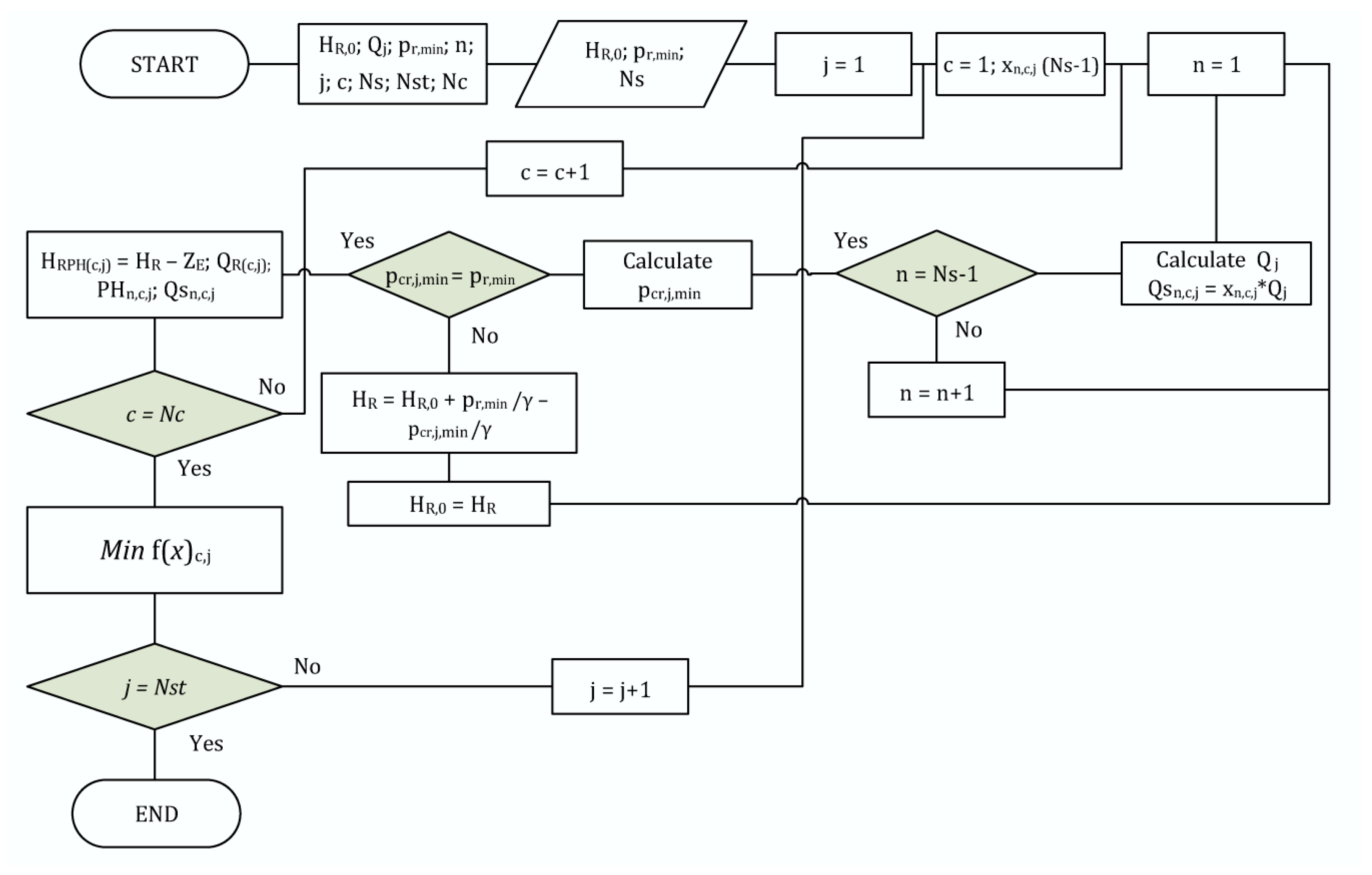
This method consists of testing a finite set of combinations of flow rates injected into the network by each of the supply sources   ( Q s n , j c ) . The process ends when the optimal enabling meets the total demand of the network while maintaining minimum energy consumption. The objective function will have to be assessed as many times as combinations of flow rates tested for a specific stage (j). The value of Q s n , j c of each source (n) is calculated as shown in Equation (3). In this case, the flow rate of the reservoir   ( Q R , j c ) is obtained as result of the model.
The number of combinations (Nc) depends on two variables: the number of sources (Ns) and the increment of x ( Δ x ) between each combination. A smaller value of Δ x and a large value of Ns entails that a large number of combinations will be evaluated. On the other hand, it has to be taken into account that the total number of evaluations of the objective function depends also on the number of stages (Nst). To apply the discrete method, it is necessary to follow the same procedure, taking into account the number of stages (Nst), the number of combinations (Nc), and the number of sources (Ns). The analysis of the next stage (j) can only be done once the minimum of the objective function has been found. The whole process is shown in the flow chart of Figure 4.
Considering the high number of combinations, the use of an optimization algorithm is justified, as described in next section.

3.2. Continuous Method

Unlike the discrete method, it is not necessary to construct a finite set of distributions of the injected flow rates to find the optimum, since the search will depend on the number of evaluations of the objective function performed by the search algorithm. It is important to select the algorithms that better fit the problem [38]. In this work, two algorithms have been chosen with the goal to contrast the results: the H-J algorithm and the N-M algorithm. Both of them share the following characteristics: (a) there is no need for derivatives of the function; (b) they allow multidimensional searching; and (c) certain types of constraints are allowed.

3.2.1. The Hooke–Jeeves Algorithm

A full description of this method can be found in [34]. This direct method performs the search in the N dimensions of the problem; therefore, N search directions are needed. Whenever a better value of the function is reached, the search moves in that direction. It could be said that this method depends on two movements: exploratory movement and pattern movement.
The exploratory movement searches through the N-dimensional function with a determined stride length. The search is performed in both positive and negative directions to find the best possible result. Once you have tested all directions and senses and a better value has been found, the search has been successful and pattern movement begins. On the other hand, if it is not possible to find a better solution, it is judged whether it has reached the optimum value—otherwise, the step length is changed and the exploratory movement begins again.
The pattern movement is a jumping movement, where the optimum previous point in conjunction with the optimum current point is used to find a third point. If this third point results in a better function value, then it becomes the new initial point and the exploratory movement starts again. On the other hand, if the third point is worse, the new initial point will be optimum current point and the exploratory movement will be reinitiated.
Special consideration should be taken regarding the stride length and the starting point of the search. A small stride length can lead to better search results, while greater one generate worse results. Nevertheless, major calculating time is needed. Moreover, the H-J algorithm has problems with local optima, so the start point has to be as close as possible to the global optimum point. This can be done by using restrictions. To be sure of achieving the optimal function value, it is recommended that some searches changing the stride length or the start point are performed.

3.2.2. The Nelder–Mead Algorithm

This algorithm is one of the best known algorithms for multidimensional unconstrained optimization without derivatives, and a full description of the method can be found in [35]. The method starts making the function evaluation for the n + 1 vertexes of a simplex. This method consists of four movements: reflection, expansion, contraction, and shrink. In each iteration, a new simplex is formed.
Once each point of the vertex is allocated with their respective function value, the worst point is reflected. If a new better function value is found, and it is within the function values of other n vertexes, the iteration is finished and the worst value is replaced. The movement of the expansion is done when the value of the function obtained from the reflection point is the best. Moreover, if the reflection point is within the two worst values or it is the worst, the contraction movement begins. If the contraction movement does not produce better function values, the shrink movement is performed. After each movement, a new simplex is built, and the search for the optimal value starts again. This procedure is repeated until a stop criterion is accomplished.
Like the H-J method, it is recommended that some searches using different starting points are performed to make sure that the values obtained are optimal.

4. Case Studies

To apply the procedures described above, two case studies are proposed. Both cases correspond to the water distribution network of two cities in Spain, one of 30,000 inhabitants (TF network) and the other of 50,000 (Catinen network). In order to develop these case studies, only the strategic models of the networks were considered. That is, for each of the networks, only the main pipes and the demand allocation are provided. These two strategic models are used to implement the setpoint curve concept and to study the differences between the discrete and continuous methods.

4.1. The TF Network

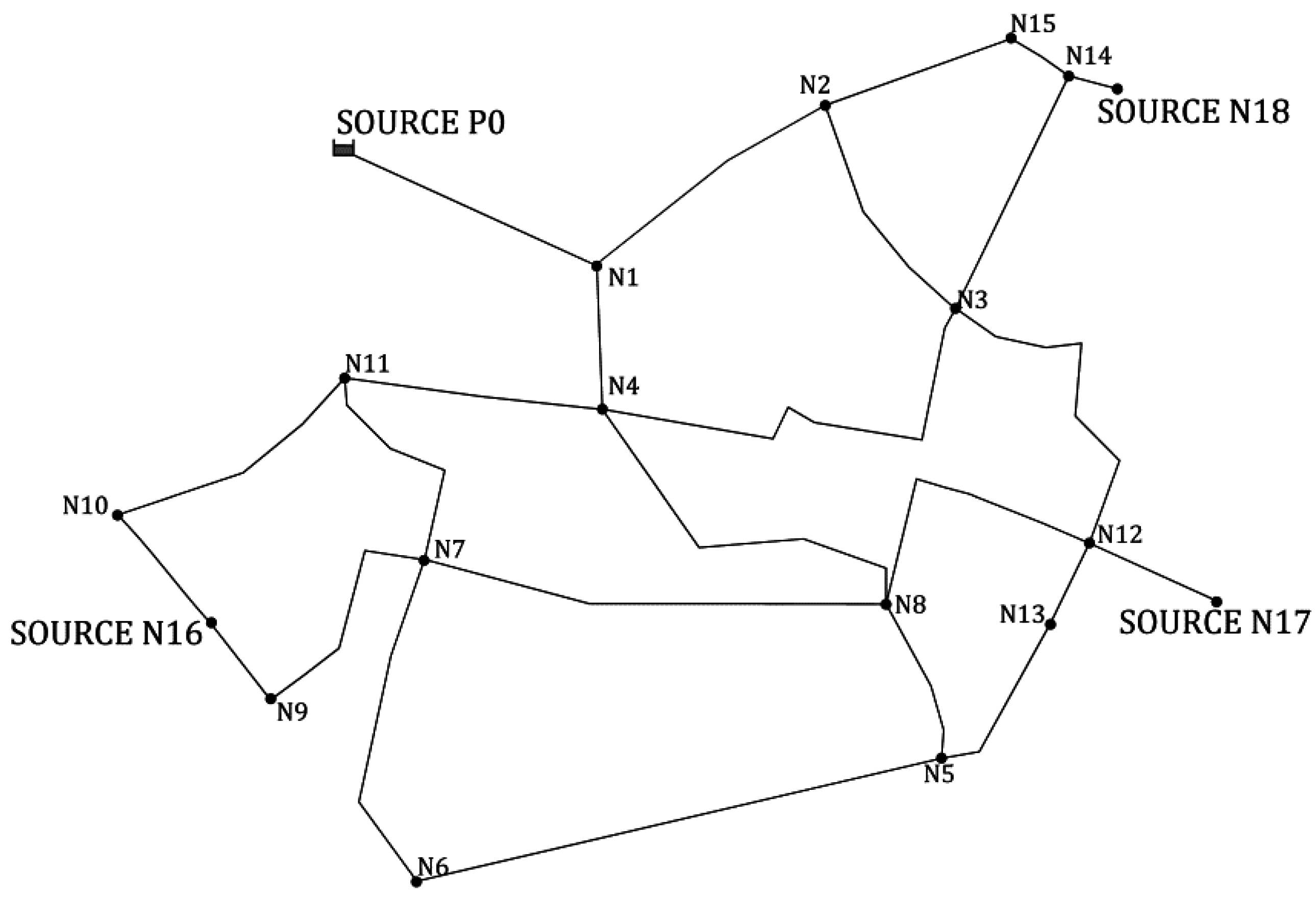
This network has four water supply sources, three of which are represented as injection nodes (N16, N17, and N18) and the other one as a reservoir (P0). The elevation of node N16 is 8 m, and the other sources have an elevation equal to zero. It has 18 nodes and 24 pipes, and the average flow rate demanded is 100 L/s. The described network can be seen in Figure 5. Information about nodes and pipelines is described in Table 1 and Table 2, respectively. The roughness of all pipelines is 0.1 mm.
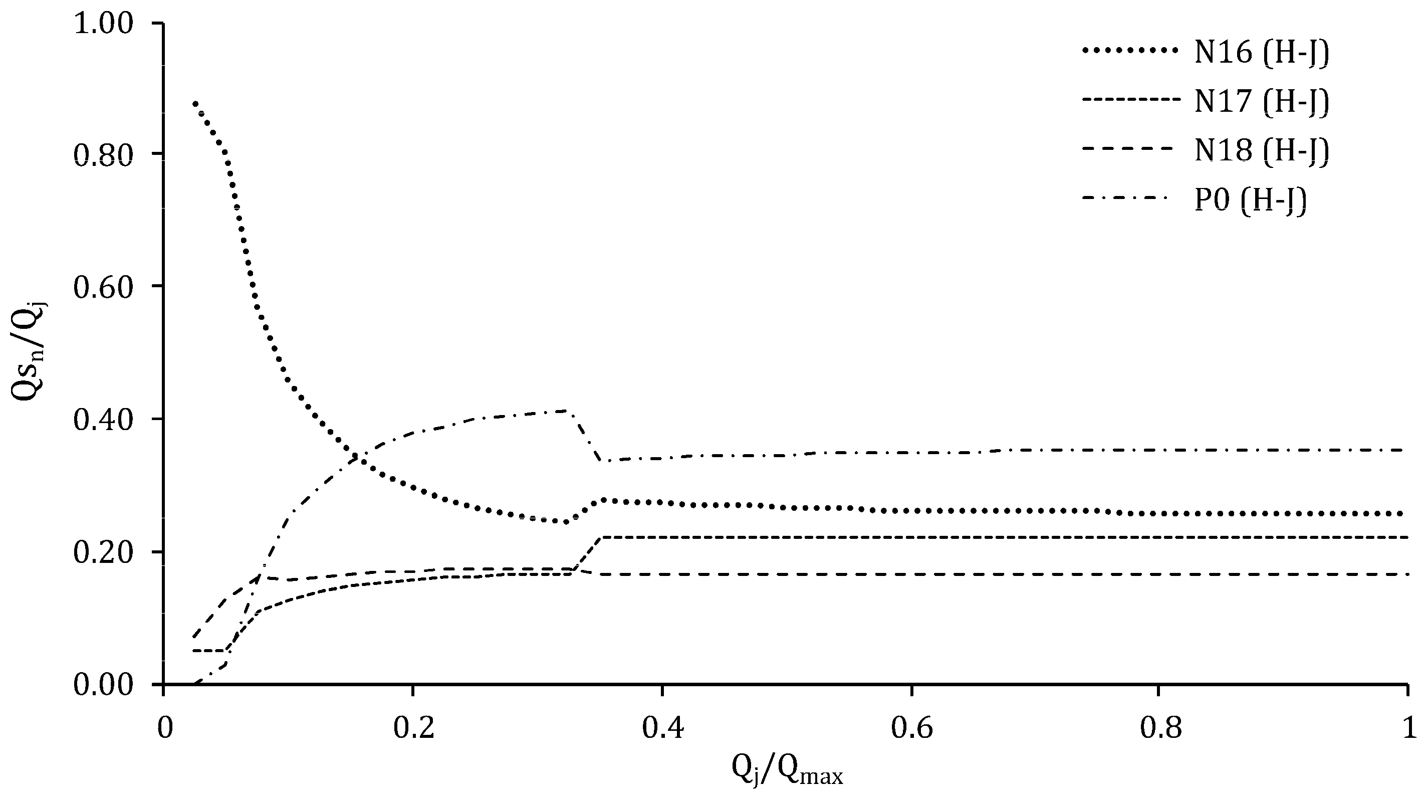
The minimum pressure required in the network is p N ,   m i n = 45 m. Figure 6 shows the distribution among the different sources applying the H-J algorithm. The X-axis represents the ratio between the demand in each stage and the maximum demand (Qmax) in the network. The Y-axis shows the relation between the flow supplied by each source and the flow demanded in each stage ( Q s n / Q j , in percentage). As is evident, this figure shows the importance of knowing the distribution among the different water sources. The flow rate distributions are influenced mainly by the potential energy of water sources, i.e., its elevation. If it is taken into account that only node N16 has potential energy, it seems logical that it will assume a major distribution quantity, as is shown in Figure 6. Otherwise, according to the flow rate demand, increased distribution becomes more uniform as a result of other variables: the location of the water sources, the network configuration, pipe sizing, multiple critical points, and others.
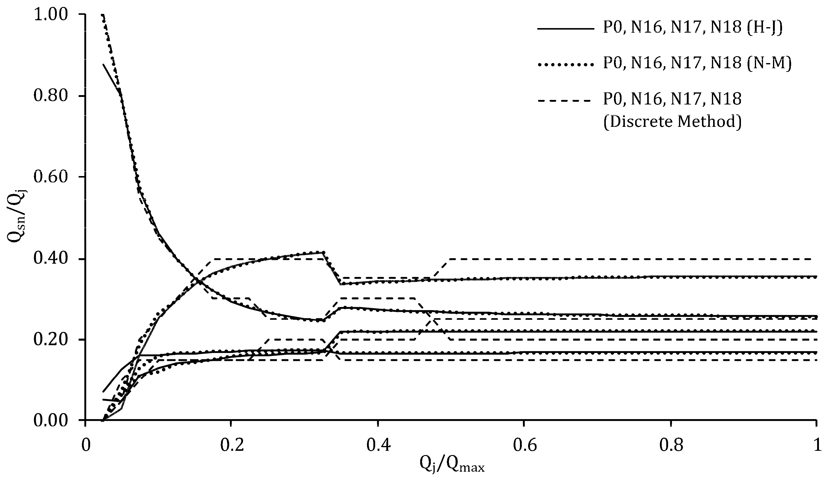
Figure 7 shows the similarities and differences between the results of the different methods. As is evident, the results are similar but not identical. In the case of the discrete method, this depends on the finite discrete set of combinations to be scanned. If a lower value of   Δ x is applied, the distribution curves between the two methods will be closer.
Moreover, in the case of the optimization algorithms, the similarity between the results will be influenced mainly by adjusting the parameters of each algorithm. In the case of the H-J algorithm, it can produce better results but it requires many more function evaluations and hence more calculation time. This is mainly due to the adjustment of the stride length to obtain reliable results. However, the starting point of the search also plays an important role at the moment of finding the optimal solution.
The N-M algorithm requires less computing time and therefore is more efficient with respect to the H-J method. This is because the N-M algorithm can define a better search direction in an easier way. Although both algorithms produce similar results, the choice of either depends on the number of evaluations of the objective function needed to make a better search for the optimal result.
One of the most important advantages of the continuous method is that it allows for an understanding of the distribution in a more precise way without the need to excessively deal with the objective function. This entails that calculation time is reduced.
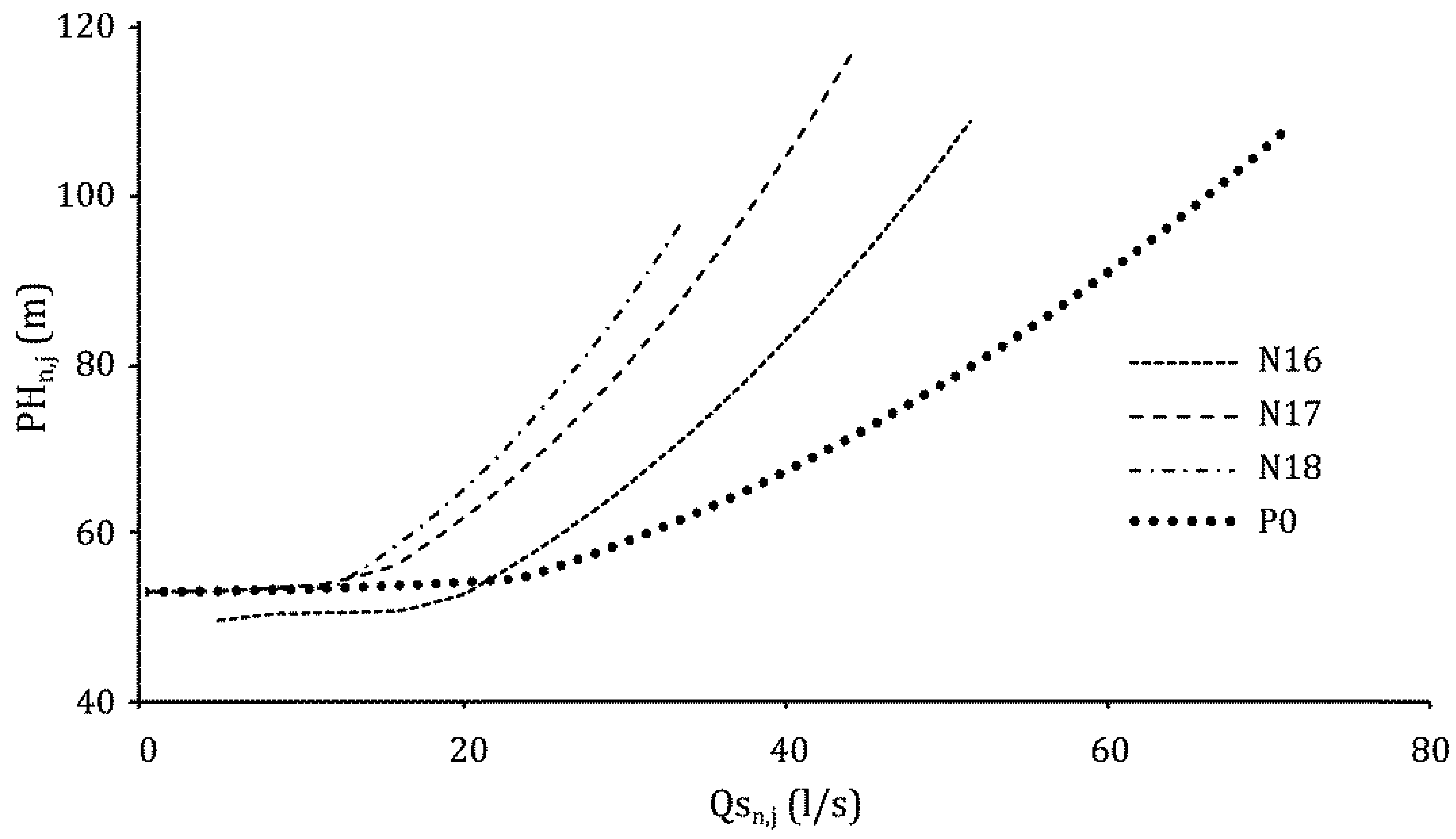
The optimal setpoint curves of each source, which are useful for regulating pumping stations, are presented in Figure 8. The curves were obtained by the H-J algorithm.

4.2. Catinen Network

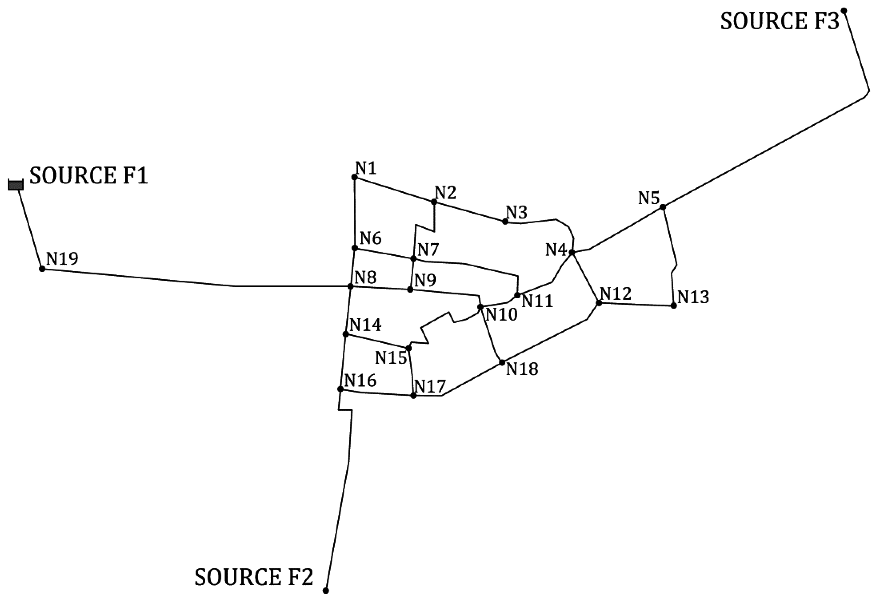
This network (Figure 9) has 30 pipes and 21 junctions, three of which are water sources, and the remainder demand nodes. The minimum pressure required is p N ,   m i n = 45 m. The average flow rate demanded is 154.20 L/s. The elevation of the three sources is zero. The information about nodes and pipelines is described in Table 3 and Table 4.
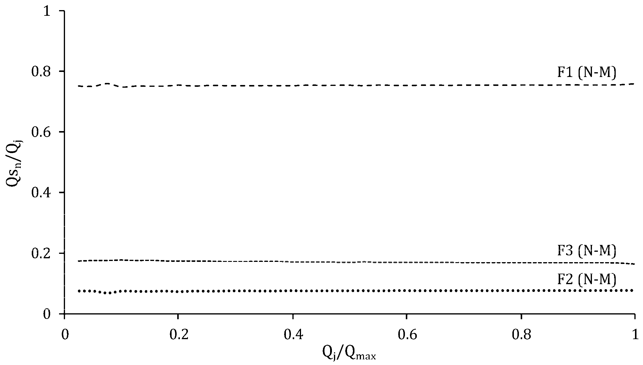
Figure 10 shows the distribution of the water sources F1, F2, and F3. The validity of different methods has been demonstrated previously in the first case study (TF network), so only the results obtained by the N-M method are presented.
Unlike the first case study, the distributions are shown to be constant. In the first case study, the critical node changes depending on the total demand flow. However, in this second case, the critical node remains unchanged for all the stages. It must be reminded that the distributions can be influenced by other factors such as network topology, energy costs, pumps efficiency, storage capacity, leakages, and others. Similarly to what was done in the previous example, setpoint curves are presented in Figure 11. It can be seen that sources F2 and F3 handle a small range of flow rates and bigger pressure heads. On the contrary, F1 deals with a major range of flow rates and requires lower pressures. Hence, these results allow for the selection of a suitable pumping station arrangement in each source.

5. Conclusions

The most relevant contributions of this work are twofold. The first deals with the setpoint calculation for multiple water sources. The importance of the setpoint curve lies in the interest of knowing the optimal pressure head and flow rate to be supplied by each water source, meeting the requirements imposed by local regulations. The second one is about the energy optimization based on the optimal distribution of flows rates that are injected to the network. Therefore, both energy consumption and leakages are kept at minimal values.
The identification of an optimal distribution of flow rates leads to decisions that lead to a better regulation of pumping systems. The method proposed in this paper also contributes to a description of the direct impact between the different sources of water in the optimum network operation when a new water production point is introduced.
The objective function has been solved through both discrete and continuous methods. Discrete methods involve a large number of calculations that are defined as a function of the number of sources and the number of combinations. The set of calculations increases as more sources of water production are considered as well as lower values of Δ x ; hence, the use of optimization algorithms is justified.
Otherwise, the continuous method allows for an exploration of a wider range of possible deals between the different water sources supply. The H-J algorithm and the N-M algorithm were chosen mainly because they are direct search methods. This means that they require neither the first nor the second derivative of the objective function. The H-J algorithm provides better optimum values. Nevertheless, it requires more computing time. Furthermore, the N-M algorithm is more efficient. The use of the two methods has served mainly to validate the results in the case studies.
The two case studies provide an improved understanding of the field of application of the methodology exposed. Important questions can be answered, for example, those related to the identification of critical water sources, the influence of its location, the quantity of water to be provided by each source, and so on. It must not be forgotten that pressure-dependent consumptions have not been considered, which will be considered in a future work.
It is important to emphasize that there are aspects that have not been considered yet, some of which have already been mentioned. The energy costs, as well as the rate policy, are perhaps the most influential. Another factor that undoubtedly affects the flow rate distribution is the storing capacity of the network. Issues such as pumps efficiency and demand curves can easily be introduced in the objective function. It is also important to take network leakages into account. In addition, this process can be combined with multi-objective functions in order to obtain economic network designs via genetic algorithms. All these problems should be addressed in future research.

Acknowledgments

This study was supported by the Program Initiation into research (Project 11140128) of the Comisión Nacional de Investigación Científica y Tecnológica (Conicyt), Chile.

Author Contributions

All authors contributed extensively to the work presented in this paper. Christian León-Celi contributed to the research, modeling, data analysis, and manuscript writing. Pedro L. Iglesias-Rey and F. Javier Martínez-Solano contributed to the research, modeling, and manuscript review. Daniel Mora-Melia contributed to the literature and manuscript review.

Conflicts of Interest

The authors declare no conflict of interest.

References

  1. Endo, A.; Burnett, K.; Orencio, P.M.; Kumazawa, T.; Wada, C.A.; Ishii, A.; Tsurita, I.; Taniguchi, M. Methods of the water-energy-food nexus. Water 2015, 7, 5806–5830. [Google Scholar] [CrossRef]
  2. Wu, W.; Gao, J. Enhancing the Reliability and Security of Urban Water Infrastructures through Intelligent Monitoring, Assessment, and Optimization. In Intelligent Infrastructures; Springer: New York, NY, USA, 2010; pp. 487–516. [Google Scholar]
  3. Yannopoulos, S.I.; Lyberatos, G.; Theodossiou, N.; Li, W.; Valipour, M.; Tamburrino, A.; Angelakis, A.N. Evolution of Water Lifting Devices (Pumps) over the Centuries Worldwide. Water 2015, 7, 5031–5060. [Google Scholar] [CrossRef]
  4. Frenning, L. Pump Life Cycle Costs: A Guide to LCC Analysis for Pumping Systems. U.S. Department of Energy’s Office of Industrial Technologies, 2001. Available online: http://energy.gov/sites/prod/files/2014/05/f16/pumplcc_1001.pdf (accessed on 27 October 2016). [Google Scholar]
  5. Perez, R.; Stark, W. The most important pump calculation. Pumps Syst. 2007, May, 24–26. [Google Scholar]
  6. Graham, S. Low life-cycle cost centrifugal pumps for utility applications. World Pumps 2007, 2007, 30–33. [Google Scholar] [CrossRef]
  7. Tolvanen, H.J. Life cycle energy cost savings and pump selection. World Pumps 2007, 2007, 34–37. [Google Scholar] [CrossRef]
  8. Marchi, A.; Salomons, E.; Ostfeld, A.; Kapelan, Z.; Simpson, A.R.; Zecchin, A.C.; Maier, H.R.; Wu, Z.Y.; Elsayed, S.M.; Song, Y.; et al. Battle of the Water Networks II. J. Water Resour. Plan. Manag. 2013, 140. [Google Scholar] [CrossRef]
  9. Giustolisi, O.; Berardi, L.; Laucelli, D.; Savic, D.; Kapelan, Z. Operational and Tactical Management of Water and Energy Resources in Pressurized Systems: The competition at WDSA 2014. J. Water Resour. Plan. Manag. 2015, 142, C4015002. [Google Scholar] [CrossRef]
  10. Vitasovic, Z.Z. An Integrated Control Strategy for the Activated Sludge Process. Ph.D. Thesis, Rice University, Houston, TX, USA, 1986. [Google Scholar]
  11. Yin, M.; Andrews, J.; Stenstrom, M. Optimum Simulation and Control of Fixed-Speed Pumping Stations. J. Environ. Eng. 1996, 122, 205–211. [Google Scholar] [CrossRef]
  12. Lingireddy, S.; Wood, D.J. Improved Operation of Water Distribution Systems Using Variable-Seed Pumps. J. Energy Eng. 1998, 124, 90–103. [Google Scholar] [CrossRef]
  13. Planells Alandi, P.; Carrión Pérez, P.; Ortega Álvarez, J.F.; Moreno Hidalgo, M.Á.; Tarjuelo Martín-benito, J.M. Pumping Selection and Regulation for Water-Distribution Networks. J. Irrig. Drain Eng. 2005, 131, 273–281. [Google Scholar] [CrossRef]
  14. Planells Alandi, P.; Tarjuelo Martín-Benito, J.; Ortega Alvarez, J.; Casanova Martínez, M. Design of water distribution networks for on-demand irrigation. Irrig. Sci. 2001, 20, 189–201. [Google Scholar] [CrossRef]
  15. Lamaddalena, N.; Khila, S. Efficiency-driven pumping station regulation in on-demand irrigation systems. Irrig. Sci. 2013, 31, 395–410. [Google Scholar] [CrossRef]
  16. Viholainen, J.; Tamminen, J.; Ahonen, T.; Ahola, J.; Vakkilainen, E.; Soukka, R. Energy-efficient control strategy for variable speed-driven parallel pumping systems. Energy Effic. 2013, 6, 495–509. [Google Scholar] [CrossRef]
  17. Diaz, J.A.R.; Montesinos, P.; Poyato, E.C. Detecting Critical Points in On-Demand Irrigation Pressurized Networks—A New Methodology. Water Resour. Manag. 2012, 26, 1693–1713. [Google Scholar] [CrossRef]
  18. Moreno, M.A.; Ortega, J.F.; Córcoles, J.I.; Martínez, A.; Tarjuelo, J.M. Energy analysis of irrigation delivery systems: Monitoring and evaluation of proposed measures for improving energy efficiency. Irrig. Sci. 2010, 28, 445–460. [Google Scholar] [CrossRef]
  19. Fernández García, I.; Montesinos, P.; Camacho Poyato, E.; Rodríguez Díaz, J.A. Energy cost optimization in pressurized irrigation networks. Irrig. Sci. 2016, 34, 1–13. [Google Scholar] [CrossRef]
  20. Carrillo Cobo, M.T.; Rodríguez Díaz, J.A.; Montesinos, P.; López Luque, R.; Camacho Poyato, E. Low energy consumption seasonal calendar for sectoring operation in pressurized irrigation networks. Irrig. Sci. 2011, 29, 157–169. [Google Scholar] [CrossRef]
  21. Fernández García, I.; Rodríguez Díaz, J.A.; Camacho Poyato, E.; Montesinos, P. Optimal Operation of Pressurized Irrigation Networks with Several Supply Sources. Water Resour. Manag. 2013, 27, 2855–2869. [Google Scholar] [CrossRef]
  22. Fernández García, I.; Montesinos, P.; Camacho, E.; Rodríguez Díaz, J.A. Methodology for Detecting Critical Points in Pressurized Irrigation Networks with Multiple Water Supply Points. Water Resour. Manag. 2014, 28, 1095–1109. [Google Scholar] [CrossRef]
  23. Araujo, L.S.; Ramos, H.; Coelho, S.T. Pressure Control for Leakage Minimisation in Water Distribution Systems Management. Water Resour. Manag. 2006, 20, 133–149. [Google Scholar] [CrossRef]
  24. Nazif, S.; Karamouz, M.; Tabesh, M.; Moridi, A. Pressure Management Model for Urban Water Distribution Networks. Water Resour. Manag. 2009, 24, 437–458. [Google Scholar] [CrossRef]
  25. Pasha, M.F.K.; Lansey, K. Strategies to develop warm solutions for real-time pump scheduling for water distribution systems. Water Resour. Manag. 2014, 28, 3975–3987. [Google Scholar] [CrossRef]
  26. Giacomello, C.; Kapelan, Z.; Nicolini, M. Fast Hybrid Optimisation Method for Effective Pump Scheduling. J. Water Resour. Plan. Manag. 2013, 193, 175–183. [Google Scholar] [CrossRef]
  27. Jung, D.; Kang, D.; Kang, M.; Kim, B. Real-time pump scheduling for water transmission systems: Case study. KSCE J. Civ. Eng. 2015, 19, 1987–1993. [Google Scholar] [CrossRef]
  28. Martínez-Solano, F.J.; Iglesias-Rey, P.L.; Mora-Meliá, D.; Fuertes-Miquel, V.S. Using the Set Point Concept to Allow Water Distribution System Skeletonization Preserving Water Quality Constraints. Procedia Eng. 2014, 89, 213–219. [Google Scholar] [CrossRef]
  29. Iglesias-Rey, P.L.; Martinez-Solano, F.J.; Mora-Melia, D.; Ribelles-Aguilar, J.V. The battle water networks II: Combination of Meta-Heuristc Technics with the Concept of Setpoint Function in Water Network Optimization Algorithms. In Proceedings of the WDSA 2012: 14th Water Distribution Systems Analysis Conference, Adelaide, Australia, 24–27 September 2012.
  30. Rossman, L.A. EPANET User Manual; United States Evironmental Protection Agency: Cincinnati, OH, USA, 2000. [Google Scholar]
  31. Ostfeld, A.; Tubaltzev, A. Ant colony optimization for least-cost design and operation of pumping water distribution systems. J. Water Resour. Plan. Manag. 2008, 134, 107–118. [Google Scholar] [CrossRef]
  32. López-Ibáñez, M. Operational Optimisation of Water Distribution Networks. Ph.D. Thesis, Edinburgh Napier University, Edinburgh, UK, 2009. [Google Scholar]
  33. Mora-Melia, D.; Iglesias-Rey, P.L.; Martinez-Solano, F.J.; Fuertes-Miquel, V.S. Design of Water Distribution Networks using a Pseudo-Genetic Algorithm and Sensitivity of Genetic Operators. Water Resour. Manag. 2013, 27, 4149–4162. [Google Scholar] [CrossRef]
  34. Hooke, R.; Jeeves, T.A. Direct search solution of numerical and statical problems. J. ACM 1961, 8, 212–229. [Google Scholar] [CrossRef]
  35. Nelder, J.A.; Mead, R. A Simplex Method for Function Minimization. Comput. J. 1965, 7, 308–313. [Google Scholar] [CrossRef]
  36. Cesario, L. Modeling, Analysis, and Design of Water Distribution Systems; American Water Works Association: St. Louis, MO, USA, 1995. [Google Scholar]
  37. Martínez-Solano, J.; Iglesias-Rey, P.L.; Pérez-García, R.; López-Jiménez, P.A. Hydraulic Analysis of Peak Demand in Looped Water Distribution Networks. J. Water Resour. Plan. Manag. 2008, 134, 504–510. [Google Scholar] [CrossRef]
  38. Mora-Melia, D.; Iglesias-Rey, P.L.; Martinez-Solano, F.J.; Ballesteros-Pérez, P. Efficiency of Evolutionary Algorithms in Water Network Pipe Sizing. Water Resour. Manag. 2015, 29, 4817–4831. [Google Scholar] [CrossRef]
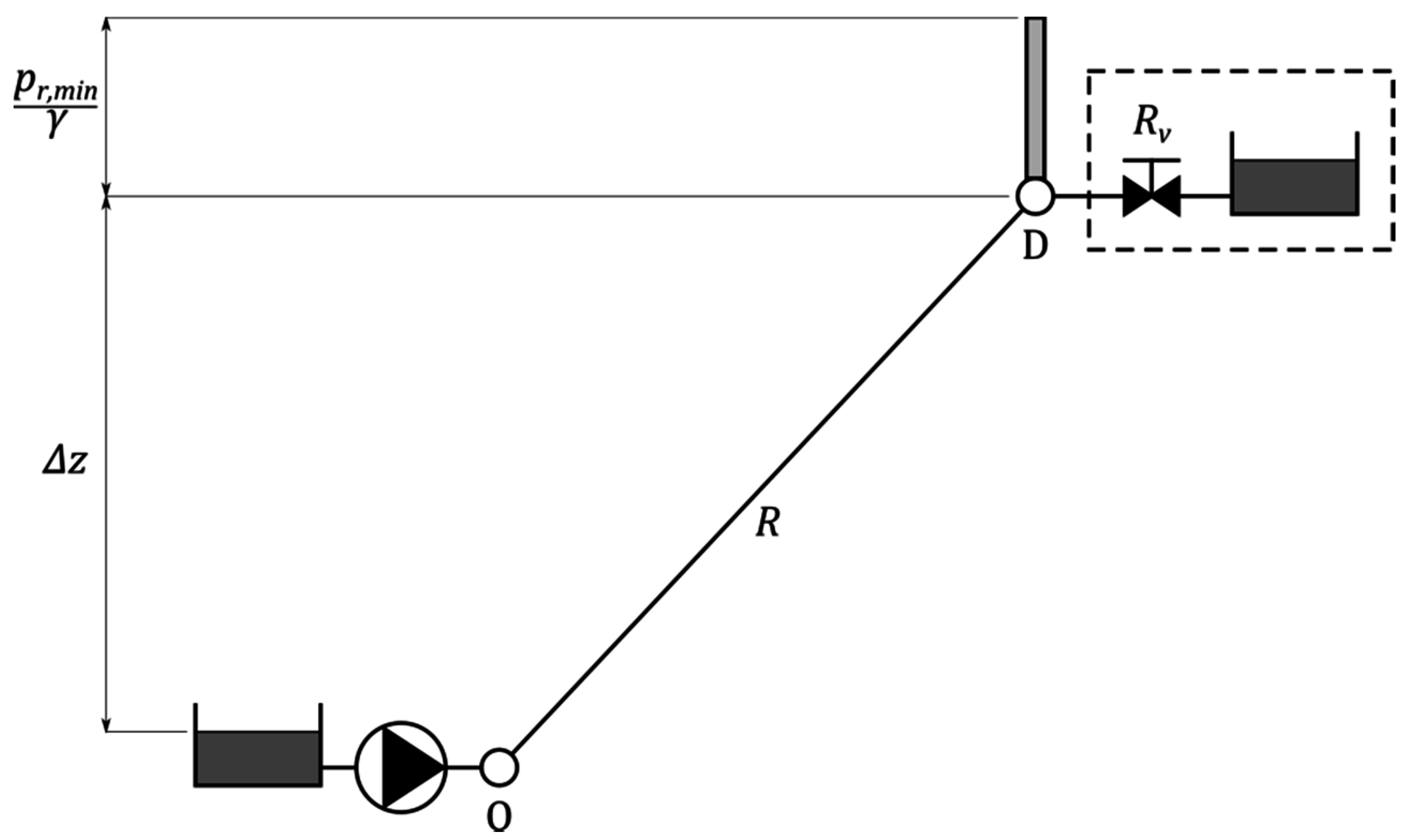
Figure 1. Supply to a consumer (D) from a pump. Setpoint curve at point O.
Water 08 00575 g001
Figure 2. Setpoint curve and resistant curve.
Water 08 00575 g002
Figure 3. Flow chart for obtaining the setpoint curve.
Water 08 00575 g003
Figure 4. The discrete method process.
Water 08 00575 g004
Figure 5. TF Network.
Water 08 00575 g005
Figure 6. Optimal flow rate distributions (the TF network).
Water 08 00575 g006
Figure 7. Flow rates distributions by the discrete method and the continuous method of Hooke–Jeeves (H-J), and Nelder–Mead (N-M).
Water 08 00575 g007
Figure 8. Setpoint curves for the four sources: N16, N17, N18, and P0.
Water 08 00575 g008
Figure 9. Catinen network.
Water 08 00575 g009
Figure 10. Optimal flow rate distributions according the N-M method (Catinen Network).
Water 08 00575 g010
Figure 11. Setpoint curves for the three sources: F2, F3, and F1.
Water 08 00575 g011
Table 1. The TF Network. Node information.
IDElev (m)Demand (L/s)IDElev (m)Demand (L/s)
N185N11710
N284N1255
N353N1342
N484N14310
N543N15315
N628N1640
N757N1700
N8610N1800
N929P000
N1075
Table 2. TF Network. Pipelines information.
Node1Node2Length (m)Diameter (mm)Node1Node2Length (m)Diameter (mm)
N1N2200150N11N4250150
N2N3150100N8N1225080
N3N4150100N5N1310060
N4N1200200N3N129860
N5N620060N3N1430080
N7N840080N14N1550080
N6N730060N2N15400100
N8N530080N1P01500250
N8N4250150N16N10125100
N7N9300100N12N135260
N10N11300100N17N1212000
N9N16125100N14N1811000
N11N730080
Table 3. Catinen network. Node information.
IDElev (m)Demand (L/s)IDElev (m)Demand (L/s)
N1911.9N127.59.4
N277.4N138.59.6
N3510.3N149.68.8
N47.54.6N157.85.3
N51017.5N161013.8
N69.65.1N177.84.3
N784.9N1868.4
N89.911N1964.4
N97.83.7F300
N1067.5F200
N115.36.3F100
Table 4. Catinen network. Pipelines information.
Node1Node2Length (m)Diam. (mm)Roug.Node1Node2Length (m)Diam. (mm)Roug.
N1N6253.26199.200.03N12N13268.10148.400.03
N2N1301.88148.400.03N12N4191.92199.200.03
N2N3260.79199.200.03N5N13391.53123.000.03
N3N4345.08123.000.03N4N11268.24148.400.03
N4N5342.25148.400.03N8N14169.26250.000.10
N6N7211.13148.400.03N14N15239.94250.000.10
N7N2301.81199.200.03N15N10384.76123.000.03
N7N9113.47199.200.03N15N17165.81148.400.03
N9N8215.97250.000.10N17N16261.97199.200.03
N8N6146.87199.200.03N17N18354.56148.400.03
N7N11459.60199.200.03N19N81047.55498.000.03
N11N10142.14150.000.10N14N16204.87199.200.03
N10N9306.66199.200.03F1N19150.00498.000.10
N10N18222.95148.400.03N5F32000.00199.200.03
N18N12438.65148.400.03N16F21300.00199.200.03