Article

Metal–Organic Framework-Functionalized Alumina Membranes for Vacuum Membrane Distillation

Department of Chemical & Biomolecular Engineering, National University of Singapore, 4 Engineering Drive 4, Singapore 117585, Singapore
*
Author to whom correspondence should be addressed.
Water 2016, 8(12), 586; https://doi.org/10.3390/w8120586
Submission received: 26 September 2016 / Revised: 25 October 2016 / Accepted: 5 December 2016 / Published: 8 December 2016
(This article belongs to the Special Issue Advanced Membranes for Water Treatment)

Abstract

:
Nature-mimetic hydrophobic membranes with high wetting resistance have been designed for seawater desalination via vacuum membrane distillation (VMD) in this study. This is achieved through molecular engineering of metal–organic framework (MOF)-functionalized alumina surfaces. A two-step synthetic strategy was invented to design the hydrophobic membranes: (1) to intergrow MOF crystals on the alumina tube substrate and (2) to introduce perfluoro molecules onto the MOF functionalized membrane surface. With the first step, the surface morphology, especially the hierarchical roughness, can be controlled by tuning the MOF crystal structure. After the second step, the perfluoro molecules function as an ultrathin layer of hydrophobic floss, which lowers the surface energy. Therefore, the resultant membranes do not only possess the intrinsic advantages of alumina supports such as high stability and high water permeability, but also have a hydrophobic surface formed by MOF functionalization. The membrane prepared under an optimum condition achieved a good VMD flux of 32.3 L/m2-h at 60 °C. This study may open up a totally new approach for design of next-generation high performance membrane distillation membranes for seawater desalination.

1. Introduction

Metal–organic frameworks (MOFs) are an emerging group of hybrid nano-porous materials [1,2]. Formed by assembling organic linkers and metal molecules into crystalline scaffolds, MOFs have extremely high surface area and porosity among the reported crystalline materials. Their pore size, porosity, functionality, crystal size and morphology can be tailored by properly choosing the organic linkers and metal clusters [3] and controlled via various techniques, such as assisted synthesis or coordination modulation [4,5,6]. Therefore, MOFs are widely regarded as versatile materials for separation, storage, drug delivery, catalysis, etc. [7,8,9,10]. Thousands of MOF structures have been synthesized and their numbers are still growing [11].
Recently, high performance mixed matrix membranes comprising MOF have been prepared by incorporating MOF nano-particles into polymer matrices [12,13,14]. These membranes exploit the advantages of the unique molecular sieve characteristics of MOF and the good processability of polymers. However, mixed matrix membranes often have defective morphology due to the voids between polymer chains and nano-particles [15,16,17]. One approach to address this issue is to prepare a continuous MOF layer on top of the supports. On one hand, this eliminates the compatibility problems at interfaces. On the other hand, it allows control over the MOF crystal orientation and membrane surface morphology.
Recently, researchers have made a significant progress in growing MOF on solid supports [18,19,20]. By controlling MOF orientation, Ben et al. prepared a poly(methyl methacrylate) (PMMA)-supported HKUST-1 (Hong Kong University of Science and Technology) membrane with high separation performance for gas mixtures, such as H2/CO2 [19]. Other support materials have also been employed, including silica, alumina, gold, etc. For example, Tan et al. have grown free-standing MOF layers on porous alumina surfaces [20]. By using lithographic techniques, they obtained MOF layers with different structures, such as needle crystals or mushroom-shaped structures. The resultant MOF surface showed good omniphobicity. These works not only presented different methods for growing MOF on solid supports, but also demonstrated that the surface structure and morphology could be effectively manipulated by tuning the MOF crystals. Thus, the development of MOF as thin surface films with desirable morphology may contribute significantly to preparing smart membranes for various separation applications.
One of the important applications is to develop membranes with super-hydrophobic properties [21,22]. Usually, high liquid repellence can be obtained with nano- or hierarchical roughness that traps air in between the membrane surface and liquid droplets [23,24,25]. In nature, typical examples of this phenomenon are plant leaves such as the lotus leaf [25], or some insects such as the water strider [26]. The understanding of surface energy and roughness on natural non-wetting surfaces has led to the development of many nature-mimetic surfaces. Tetuja et al. have fabricated super-hydrophobic surfaces with hierarchical roughness by using nanoparticles [27]. In this work, we aim to design nature-mimetic membranes with super-hydrophobic properties for membrane distillation (MD) as seawater desalination. The micro-structured surface formed by MOF crystals may enable us to create super-hydrophobic membranes.
A novel two-step synthetic strategy was adopted in this study to prepare such nature-mimetic hydrophobic membranes; namely, (1) to develop a MOF functionalized surface on alumina tube supports and (2) to introduce perfluoro molecules onto the MOF surface to lower the surface energy, thus increasing hydrophobicity. More specifically, NH2-MIL-53(Al) (MIL: material from Institut Lavoisier) would be grown on the alumina support membrane owing to its good compatibility with the alumina substrate. In addition, its Al element on the substrate surface could be used as the active sites for MOF growth. Consequently, intergrown MIL-53(Al) crystals would be formed, which not only eliminates the delamination issue but also allows the synthesis of nano- and hierarchical roughness by controlling the aspect ratio of MIL-53(Al) [28]. NH2-MIL-53(Al) is an amino derivative of MIL-53(Al), which utilizes 2-amino terephthalic acid as the organic linker. The amino group is of particular interest here because it can react with perfluorooctanoyl chloride to increase the surface hydrophobicity significantly. The detailed reaction mechanisms will be discussed in the results section.
Once hydrophobic membranes with an ultrathin top MOF layer are obtained, the resultant membranes may possess the intrinsic advantages of the alumina support, such as high temperature and pressure resistance, high water permeability [29] and a hydrophobic surface formed by MOF functionalization. Thus, thoroughly investigations are carried out in this work to evaluate if these membranes are suitable for seawater desalination by means of vacuum membrane distillation (VMD) [30,31,32,33,34]. To our best knowledge, this is the first time that MOF-functionalized alumina membranes are used in MD desalination applications. This work may open up new opportunities to design superior membranes for MD and other applications.

2. Experimental Section

2.1. Materials

The commercial Inocep® alumina tube (average pore size 200 nm, inner diameter 2.7 mm and outer diameter 3.7 mm, Hyflux Pte Ltd.) was used as the porous support. In addition, 2-aminoterephthalic acid (Sigma Aldrich) was utilized as the organic linker for MOF. Aluminum nitrate and aluminum acetylacetonate supplied by Sigma Aldrich were acquired as the Al sources for MOF growth. Perfluorooctanoyl chloride (Alfa Aesar) was employed in the reaction to increase membrane hydrophobicity. Acetic acid, ethanol and anhydrous tetrahydrofuran (THF) used in the experiments were purchased from Merck. Deionized (DI) water produced by a Milli-Q unit from MilliPore with the resistivity of 18 MΩ·cm was used as the solvent, while sodium chloride (NaCl) acquired from Merck was to prepare the model seawater.

2.2. Preparation of MOF-Functionalized Hydrophobic Membranes

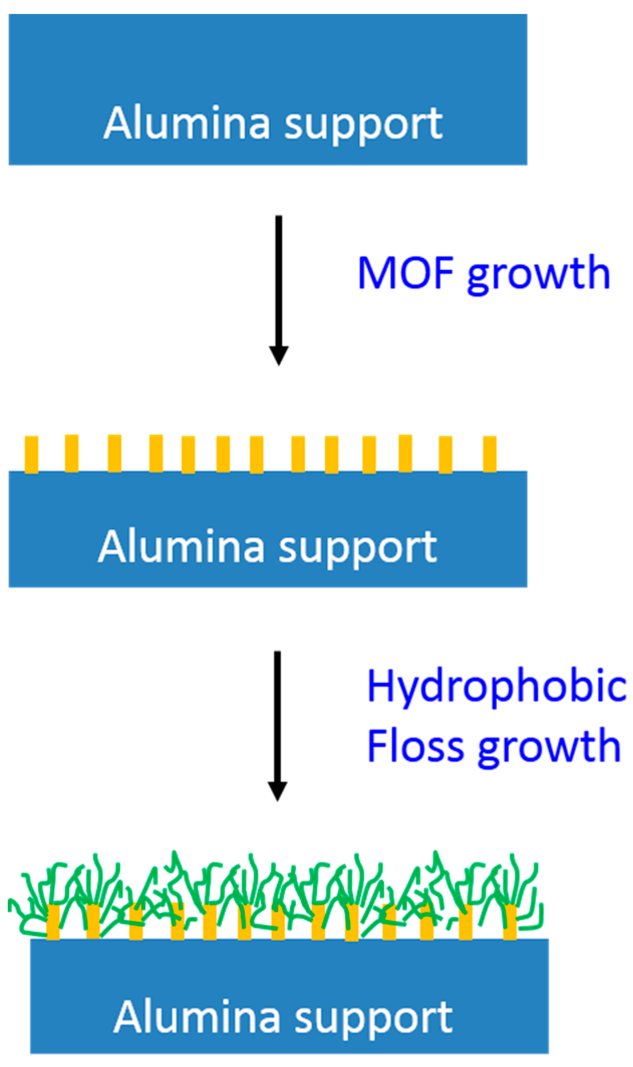
2.2.1. MOF Growth on the Alumina Support

The alumina tubes were cut into ~7 cm length pieces. These pieces were sonicated in a water batch for 20 min before usage. Then 2-aminoterepthalic acid was firstly weighed and suspended in DI water to make a 1 wt % solution. Subsequently, acetic acid was added into the solution with a concentration of 1 wt %. The resultant mixture was sonicated for 20 min to ensure even dispersion. Then, the solution was transferred to a Teflon-lined stainless steel autoclave, and a piece of alumina tube was immersed in it. The autoclave was sealed and placed in an oven at 120 °C for 3 days to carry out the thermal reaction. After the reaction, the alumina tube was rinsed with ethanol three times and dried in an oven at 60 °C overnight for later usage. The produced alumina tube was named as the first growth tube.
The first growth tube above was subjected to a second MOF growth step to increase the MOF layer coverage on membrane surface. A 1 wt % 2-aminoterepthalic acid/water solution was firstly prepared, then an Al source (aluminum nitrate or aluminum acetylacetonate) of 1 wt % was added into the solution. The resultant mixture was sonicated for 20 min. Subsequently, the first growth tube was immersed in it. The whole mixture was placed in an oven at 80 °C for different durations (50, 24, 5, 1 or 0.5 h). Lastly, the alumina tube was rinsed with ethanol three times and dried in an oven at 60 °C overnight. The resultant tube was noted as the second growth tube.

2.2.2. Growth of the Hydrophobic Floss

The second growth tube was treated with perfluorooctanoyl chloride for the growth of hydrophobic floss. Firstly, a 5 wt % perfluorooctanoyl chloride in a THF solution was prepared. The second growth tube was placed into the solution, and the mixture was rest at room temperature for 5 h. After that, the tube was rinsed with ethanol three times and dried in oven at 60 °C overnight. Figure 1 describes the preparation steps for the MOF-functionalized hydrophobic membrane.

2.3. Membrane Characterizations

The membrane morphologies were observed by field emission scanning electron microscopy (FESEM, JEOL, JSM-6700LV). The FESEM samples were prepared by fracturing the alumina tube membranes and coated with platinum using a JEOL JFC-1200 ion sputtering device.
The average pore sizes of the alumina tube membranes before and after MOF functionalization were measured by a CFP-1500 AE capillary flow porometer (PMI, Vista, CA, USA). The sample was prepared by immersing one piece of membranes in a PMI Galwick solution (surface tension of 15.9 dynes/cm) for 1 day to assure total wetting [35]. Then, it was loaded into the porometer for measurements.
Since scanning electron microscope (SEM) cannot observe the differences after perfluoro molecule growth on the second growth tube, the changes in surface chemistry before and after MOF functionalization were measured by X-ray photoelectron spectroscopy (XPS, Kratos AXIS His spectrometer). The surface elemental distribution was detected by X-ray energy dispersive spectrometry (EDX) using an Oxford INCA energy dispersion of X-ray system together with a super ultrathin window (SUTW) connected to a SEM (JEOL, JSM-5600LV) operating at 15 kV.
The X-ray diffraction (XRD) patterns of the pristine and MOF-functionalized membranes were obtained using wide angle X-ray diffraction (GADDS WXRD system, Bruker D8 advanced diffractometer) at room temperature. The measurement covers a scan range of 2θ = 2.0° to 33.5° with Ni-filtered Cu-Kα radiation at a wavelength λ = 1.54 Å.
The chemical structure changes before and after the growth of hydrophobic floss were analyzed by using Fourier transform infrared-attenuated total reflection (FTIR-ATR; Perkin-Elmer Spectrum 2000 FTIR spectrometer). Each membrane sample was purged with nitrogen for 30 min before the spectra was taken with an average of 16 scans.
The water contact angles of the pristine and MOF-functionalized membranes were measured by a Rame-Hart Contact Angle Goniometer (model, 100-22). Deionized water was dropped onto the membrane surface by a Gilmont micro-syringe. The water contact angle images were recorded.
The liquid entry pressure (LEP) of alumina tube membranes were determined to study the wetting resistance. Figure 2 shows the lab-made setup [36,37]. A 200 mL stainless steel cylinder was used as the reservoir of salt water containing 3.5% NaCl. A pressure gauge was installed at the top of the cylinder. Before the measurement, the membrane module was prepared and the outlet of the feed side (lumen side) was sealed. Then, the inlet of the feed side was connected to the reservoir cylinder. During the test, hydraulic pressure was introduced from the compressed nitrogen, and increased with a step of 0.1 bar at an interval of 5 min. The test was run until a drop of water was observed on the shell side of the membrane. The pressure at which the water penetrated through the membrane was determined as the LEP of the membrane sample.

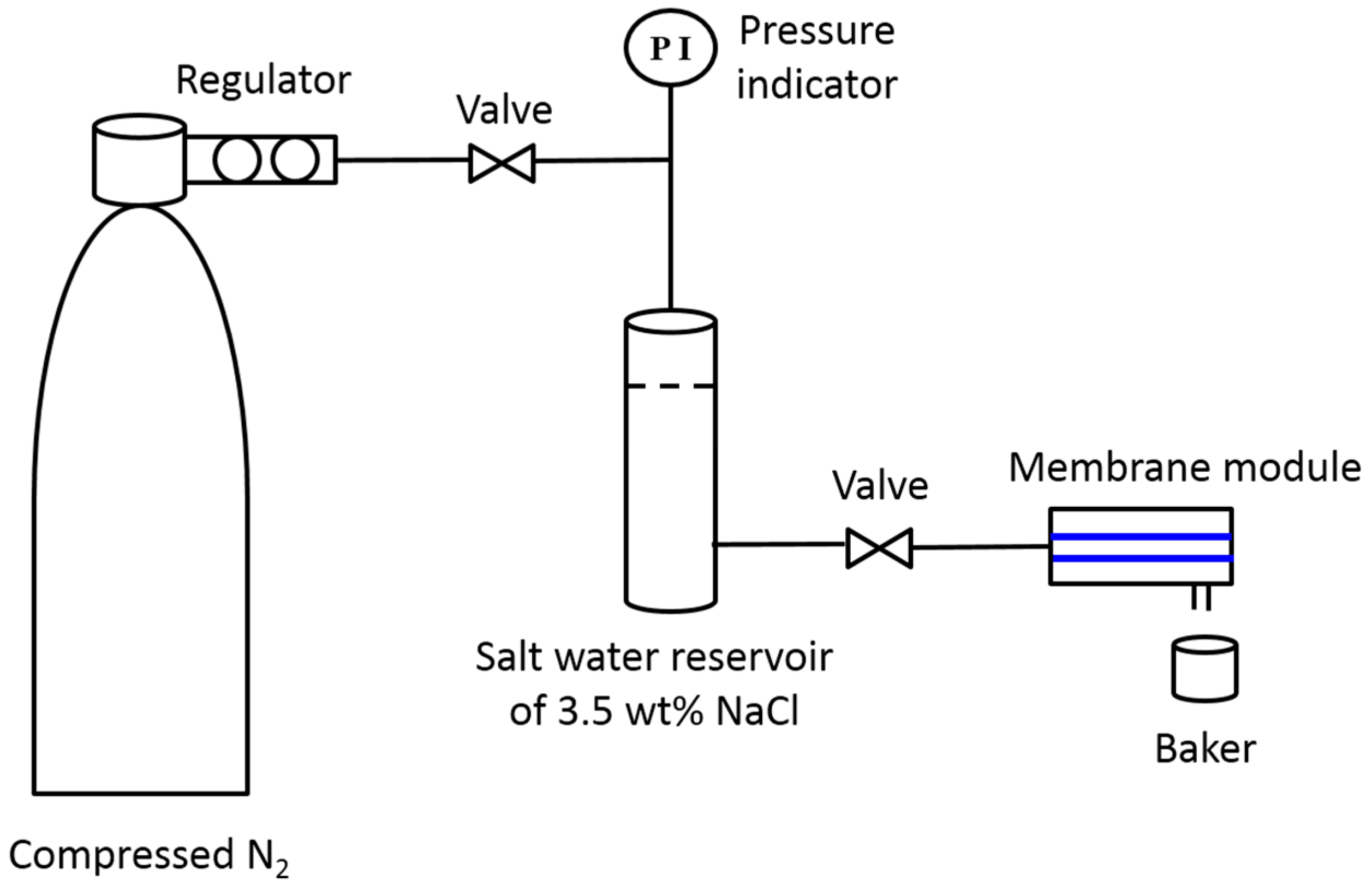
2.4. VMD Desalination Experiments

The VMD experiments were carried out to evaluate the desalination performance of MOF-functionalized alumina membranes. In VMD, a pressure difference is created across the membrane by a vacuum pump, which is the driving force for water vapor permeation. Compared to other MD configurations, VMD has the advantages of better thermal efficiency and higher permeation flux [38,39,40]. However, due to the applied vacuum, the VMD membranes require a higher wetting resistance and radial-direction membrane rigidity than other MD configurations [41]. Thus, the MOF-functionalized alumina membranes are advantageous in VMD applications because of the good mechanical stability and surface hydrophobicity [30,37].
The schematic drawing of a laboratory-scale VMD setup has been described elsewhere [42]. Before running the experiment, the alumina tube membrane sample with an effective membrane area of 4.4 cm2 was mounted into a testing module. Model seawater (5 L 3.5 wt % NaCl) was used as the feed solution. The feed temperature was controlled at 40, 50 and 60 °C by a heater and circulated to the testing module by a rotary pump at 12 L/h. On the other hand, the permeate side of the membrane was connected to a vacuum pump, and the pressure was maintained at around 20 mbar. The permeate samples were collected by cold traps immersed in liquid nitrogen. After being conditioned for 0.5 h, samples were taken at an interval of 10 min, and weighed by an accurate balance (A&D, GR-200). The salinity of the samples was analyzed by a conductivity meter, Lab 960 m (0–500 ms·cm−1, ±0.1 μs·cm−1 for the measuring range of 0–200 μs·cm−1, SCHOTT instrument). For each condition, at least four samples were collected and the average data were reported. The water permeation flux (Jw) was calculated according to the following equations:
J w = m A   ×   t
where m is the mass of the permeate sample collected over time t, and A is the effective membrane area. The salt rejection of the membranes was determined from:
β = ( 1 c p c f ) × 100 %
where cp and cf are the NaCl concentrations in permeate and feed solutions, respectively. During the VMD tests, the membranes had a salt rejection of 99.9% unless specifically highlighted.
In order to make sure the reproducibility of the alumina tube membranes, repeated VDM tests were performed for all membranes prepared. Deviations in terms of permeation flux were all within 10%. The average data were reported.

3. Results and Discussion

3.1. Growth of MOF on Alumina Membranes

Figure 3a,b show the FESEM morphology of the inner and outer surfaces of the pristine alumina tube membrane. The inner surface morphology is highly organized and regular, while the outer surface appears to be very disorganized and amorphous. Hence, it may be achievable to grow even MOF coverage on the inner side. Figure 3c displays the inner surface morphology of the first growth tube membrane. Crystals with sizes of 1–3 μm are clearly observed on the membrane surface. The reaction between alumina membrane and 2-aminoterepthalic yielded blocks of NH2-MIL-53(Al) microcrystals under the hydrothermal condition. Under closer scrutiny in Figure 3c, these crystals are partially embedded in the membrane surface. This is because that the alumina membrane not only functions as a solid support, but also the Al source for the growth of MOF. The presence of acetic acid in the reaction solution helps to slowly release the Al source from the membrane surface [23]. Hence, the NH2-MIL-53(Al) crystals are intergrown from the alumina surface. Therefore, the MOF crystals are immobilized on the membrane surface, and will not delaminate from the surface during actual applications.
However, although NH2-MIL-53(Al) crystals are successfully formed, their coverage on alumina surface is not enough for membrane applications. Those uncovered spots are possible defects that may sacrifice membrane separation performance. Thus, a second MOF growth phase is performed to increase the surface coverage. Compared to the first MOF growth phase, the growth in the second MOF phase is much easier as the crystal seeds are already formed. Therefore, a much milder hydrothermal condition is used in this step.
Figure 4 shows the surface morphology after the second growth phase for 50 h using different aluminum sources of (a) aluminum nitrate and (b) aluminum acetylacetonate. For both cases, large surface coverages are observed because a great number of MOF crystals are formed. The major difference between these two aluminum sources is the shape of the resultant MOF crystals. In the case of aluminum nitrate, flower-like crystals are obtained, where each crystal piece is like a petal of flower. In the case of aluminum acetylacetonate, ordered nanocrystals are formed, which cover the entire substrate surface. These morphological differences are attributed to the different activity of the two aluminum sources [29,43]. Since aluminum nitrate has a larger solubility in the reaction solvent of water, more free Al ions are available in the solution. Therefore, the MOF crystals grow rapidly and radically towards the bulk solution. On the other hand, because aluminum acetylacetonate has lower solubility in water, small MOF crystals are formed due to limited free Al ions around the crystal seeds because of concentration polarization.
Although the MOF morphologies are different, both types have their own advantages and shortcomings. For the formal case, since the petals have an approximately 2-dimensional (2D) structure, they possess a high aspect ratio. This is desirable because it promotes the effective membrane surface area. Moreover, the micro-petals display a larger hierarchical roughness than in the latter case, which may contribute positively to membrane hydrophobicity. However, since the petals are not well aligned, some surfaces are not covered by the crystals. They are potential defective areas for membrane applications. In contrast, the latter case shows a much denser MOF layer structure, which reduces the possibility of membrane defects and membrane wetting. Therefore, both MOF morphologies have their unique advantages. Consequently, both second growth tubes may be good precursors for the preparation of hydrophobic membranes.
To chemically validate the successful NH2-MIL-53(Al) MOF formation, EDX and XRD measurements are carried out. Figure 5 displays the EDX element distributions on the crystals formed from the two aluminum sources. Both images show a similar atomic ratio among the four major elements, C, N, O and Al, and the small discrepancies may be due to equipment inaccuracy. Generally, N and Al elements have a 1:1 atomic ratio, which reflects 1:1 coordination between 2-amino terephthalic acid and Al ion in the crystal structure. This is in accordance to the NH2-MIL-53(Al) chemical formulation. Figure 6 shows the structure formula of the formed NH2-MIL-53(Al) framework. One Al ion is coordinated by one organic linker on the average. The results confirm the successful formation of NH2-MIL-53(Al) MOF crystals. Figure 7 shows the XRD pattern of the pristine alumina membrane and the second growth MOF tubes from both aluminum sources. The second growth tubes exhibit additional peaks at two theta values around 9°, 10° and 15°. These are the characteristic peaks of MIL-53 crystals at the directions of [101], [200] and [011], respectively [23]. The XRD result further validates the successful formation of MOF crystals after the second growth phase.

3.2. Growth of Hydrophobic Floss

After the growth of hydrophobic perfluoro molecules on the two NH2-MIL-53(Al) functionalized membranes, they were tested under VMD for seawater desalination. Table 1 summarizes their separation performance. The membrane grown from aluminum nitrate has water leakage during the test because the MOF crystals and hydrophobic floss do not cover the membrane substrate fully, as revealed in Figure 4a. Those defective areas allow the seawater to pass through the membrane, and result in the loss of membrane selectivity. In contrast, the membrane prepared from aluminum acetylacetonate shows a flux of 6.2 L/m2-h and a salt rejection of 99.9% at a feed temperature of 60 °C. Figure 8 presents the cross-section morphology of the resultant membrane. MOF crystals can be clearly observed from the cross-sectional view, which cover the entire membrane surface. This demonstrates the feasibility of preparing MOF-based hydrophobic membranes for MD applications. Therefore, this membrane is further characterized to reveal the membrane characteristics, including chemical structure, pore size, wetting resistance and water contact angle before and after the hydrophobic floss growth.
Since no differences can be observed by SEM after perfluoro molecule growth, Figure 8 compares the C1s XPS spectra among the pristine alumina membrane, the second growth tube and the final hydrophobic membrane. The pristine membrane displays one peak, which is the reference condition. With the growth of MOF crystals, one additional C1 peak appears at higher binding energy due to the new carbon environment introduced from 2-amino terephthalic acid. Then, two new C1 peaks appear at around 289 and 291 eV binding energy after the growth of hydrophobic floss. These two high binding energy are the characteristics of carbon atoms that have double bonds or bonds with halogen elements [44,45]. Therefore, they can be assigned to CF2 and CF3 in the perfluoro molecule, respectively. In summary, this XPS spectrum signifies the successful grafting of the perfluoro molecules on the MOF-functionalized membrane. In addition, FTIR measurements were also carried out to examine the chemical property changes in the second growth tube and the final hydrophobic membrane. As shown in Figure 9, the CF functional group can be distinguished from the FTIR spectra at the wavenumbers of 1050 cm−1 after the hydrophobic floss growth [46,47]. This further validates that the perfluoro molecules have been successfully added to the membrane surface.
Figure 10 displays the evolution of mean pore size change before and after the hydrophobic floss growth measured by PMI porometer. The pristine alumina membrane has a mean flow pore size of 0.19 μm, which is in agreement with the value provided by the supplier. After being functionalized by MOF crystals, the mean pore size stays roughly the same. This is desirable because the MOF layer does not block the substrate pores and increase transport resistance across the membrane significantly. Nonetheless, some smaller pores are observed in Figure 10b compared to Figure 10a. These smaller pores may result from the growth of MOF crystals, yet they do not change the mean membrane pore size because of the small percentage. Figure 10c displays that the mean pore size is reduced to 0.09 μm after the growth of hydrophobic floss. This reflects that the hydrophobic floss has effectively covered the membrane surface and restricted the membrane pore size. This pore size is in the optimal range of VMD membranes because it can generate higher membrane resistance against wetting [48,49].
The wetting resistance and hydrophobicity of the resultant membrane were experimentally determined. Table 2 lists the LEP values of the membranes before and after hydrophobic floss growth. As expected, the second growth tube is wetted by water without applying any hydraulic pressure. After the hydrophobic treatment, the LEP increases to 3 bar. This is owing to the reduced surface pore size and increased hydrophobicity [50,51,52]. Figure 11 displays the water contact angles of the tubular membranes. For the pristine alumina membrane, the water droplet quickly wets the inner surface due to its hydrophilicity. Therefore, a water droplet is not captured in Figure 11a. After the growth of the MOF layer, a water droplet can be formed on the inner membrane surface. Nevertheless, the surface is still in the hydrophilic range as the water contact angle is less than 90°. This explains the low LEP value obtained from the second growth tube membrane. Finally, after the hydrophobic floss growth, the water contact angle increases largely. A well-shaped water droplet is clearly observed. However, the exact contact angle is not obtained because of the curved membrane surface. Nonetheless, these images explicitly exhibit the increase in membrane hydrophobicity. Once again, the results in wetting resistance and hydrophobicity clearly demonstrate the successful preparation of MOF functionalized hydrophobic membranes.

3.3. Effect of Second MOF Growth Time on Membrane Performance

After the attainment of the hydrophobic membrane, its VMD separation performance is further improved. Table 3 tabulates its VMD performance as a function of reaction time for the second MOF growth. The permeation flux increases with decreasing duration for the second MOF growth phase because a looser MOF layer may form in a shorter reaction time. As a result, the vapor transport resistance is reduced and the permeation flux is increased. However, there is a minimum reaction duration to grow sufficient MOF crystals in order to cover the entire membrane surface. Below that duration, defects may remain on the membrane surface. It is noted that when the reaction time is reduced to 0.5 h, the final membrane can only operate at 50 °C. Membrane leakage is observed at the start of the experiment when the feed temperature is set to 60 °C because higher thermal motion at high feed temperatures may induce defects. Therefore, the minimum reaction duration for the second MOF growth phase is about 1 h in this case.
The final membrane prepared from the optimum condition shows a good flux of 32.3 L/m2-h at 60 °C feed temperature. Table 4 compares it with other VMD membranes made from various materials for seawater desalination [53,54,55,56,57,58]. The newly designed membrane exhibits a superior flux owing to its unique morphology formed from a nature-mimetic surface structure. The microstructure control of MOF crystals and the hydrophobic floss growth have enabled the novel membrane for VMD applications. Therefore, this work may provide useful guidelines to develop a new type of membranes for MD applications.

4. Conclusions

In this work, nature-mimetic membranes with hydrophobic properties were designed by growing and functionalizing MOF with desirable morphology on alumina substrates for seawater desalination via VMD. The following conclusions can be drawn from the current study:
(1)
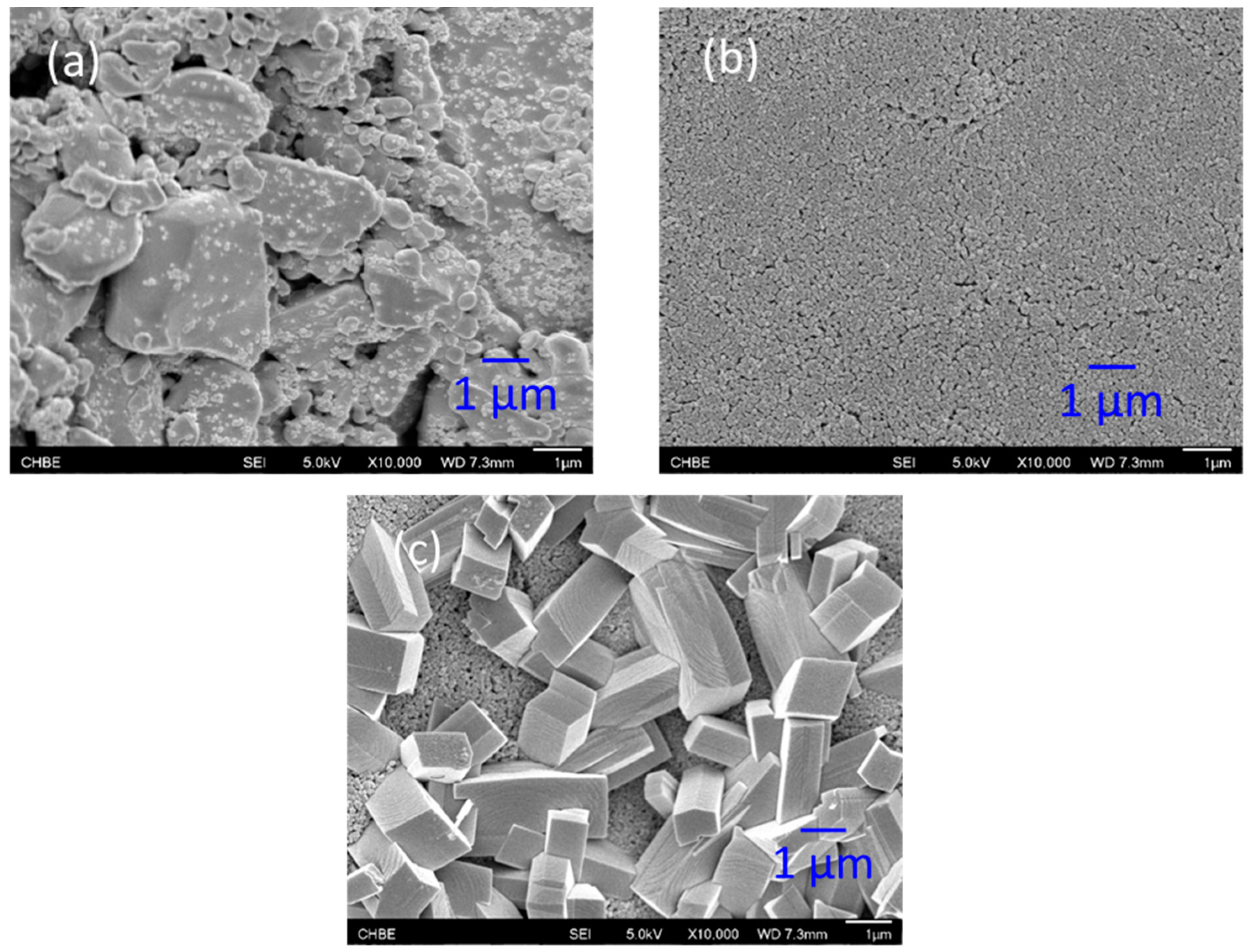
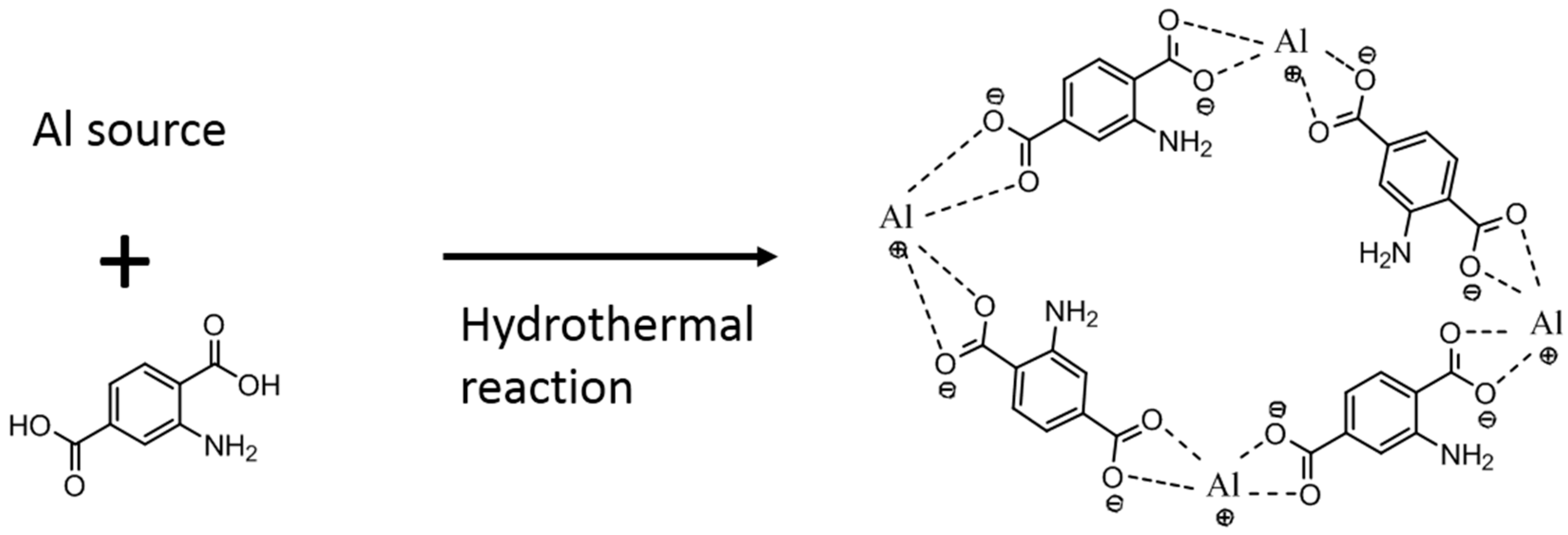
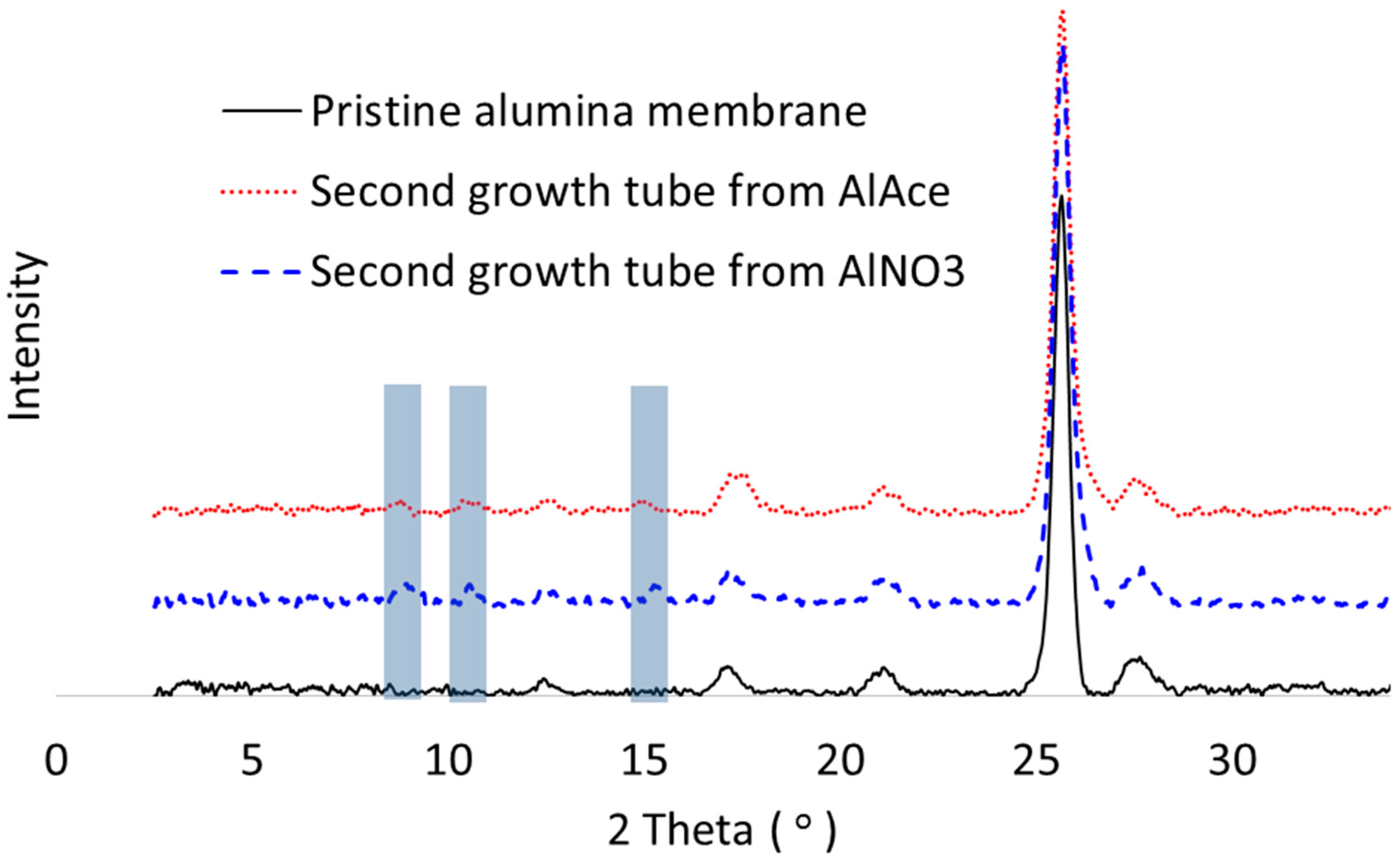
NH2-MIL-53(Al) MOF crystals have been successfully formed on alumina supports via hydrothermal reaction. The alumina substrate functions not only as a solid support, but also provides the Al sites for MOF growth. Thus, the crystals were intergrown from the support surface and immobilized on the surface.
(2)
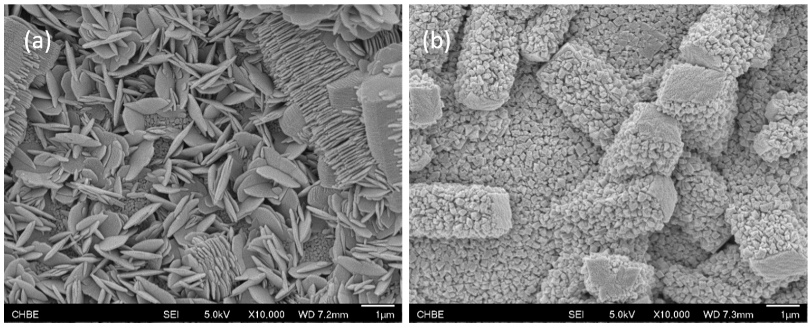
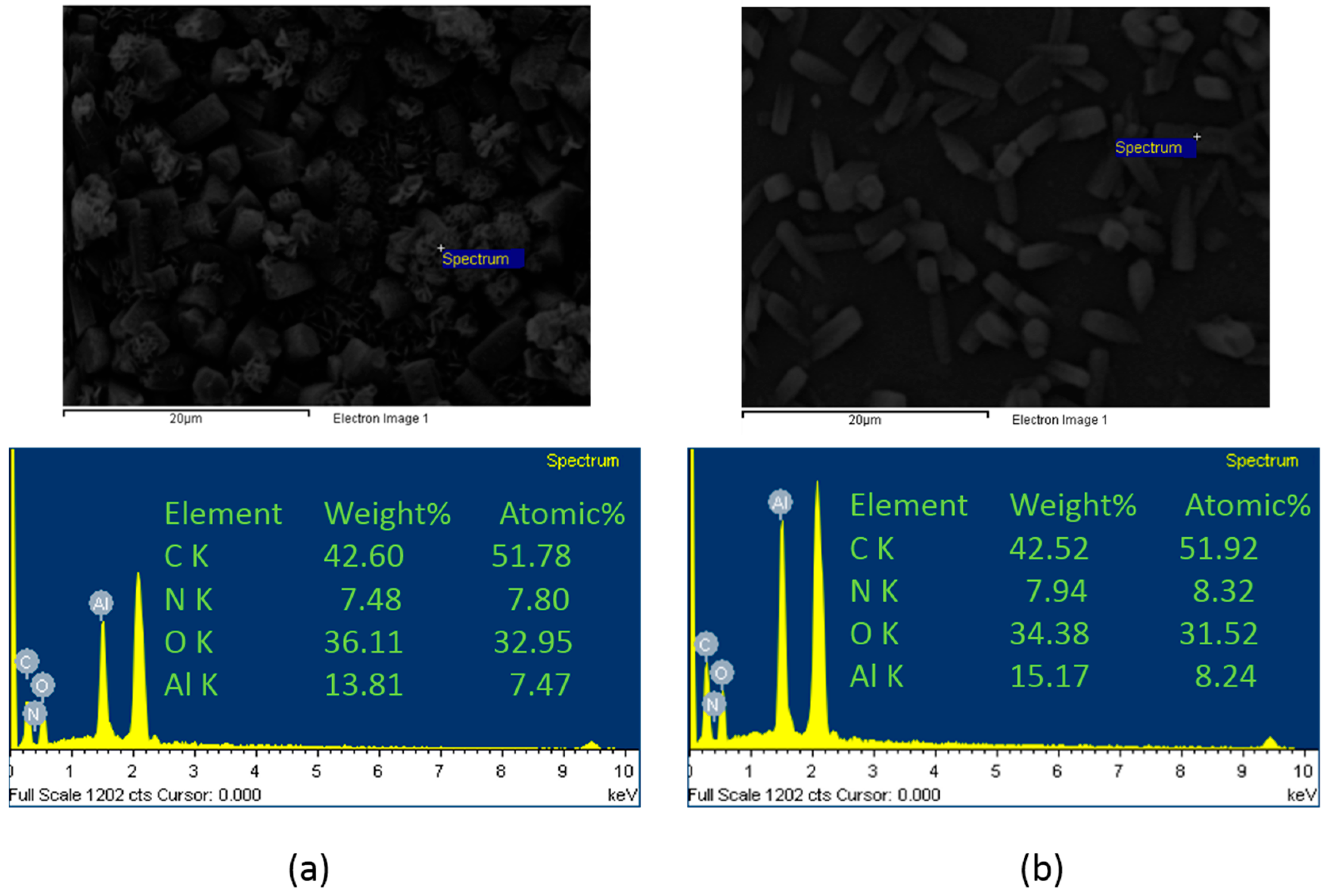
Different MOF morphologies were achieved through the manipulation of different alumina sources in the second growth phase. The micro-petal crystal morphology from aluminum nitrate had a 2D-like structure, which possessed a high aspect ratio. However, the substrate surface was not fully covered by these crystals due to the distance among the petals. On the other hand, the ordered nanocrystals morphology from aluminum acetylacetonate covered the entire substrate surface and was able to reduce the membrane defects.
(3)
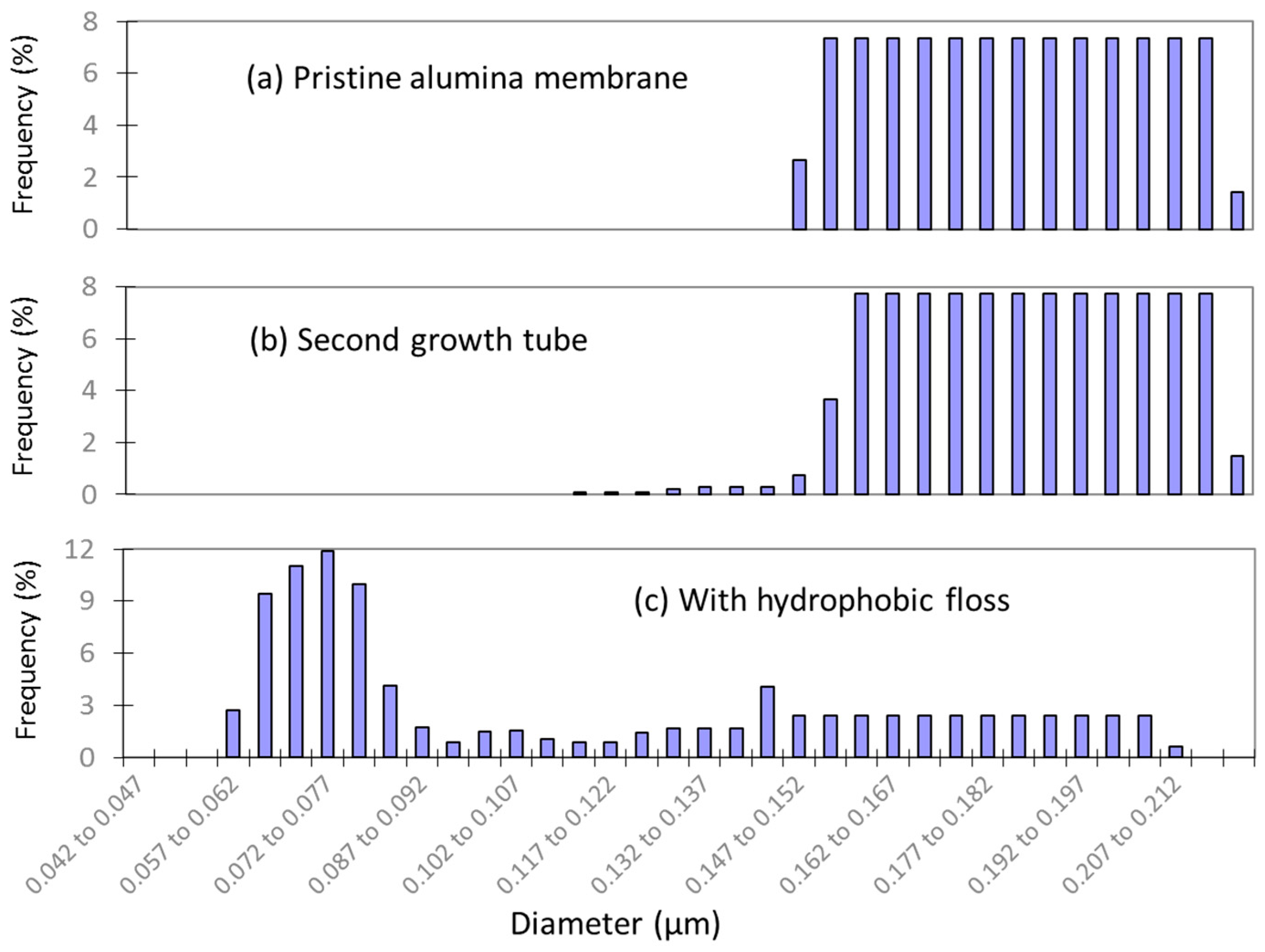
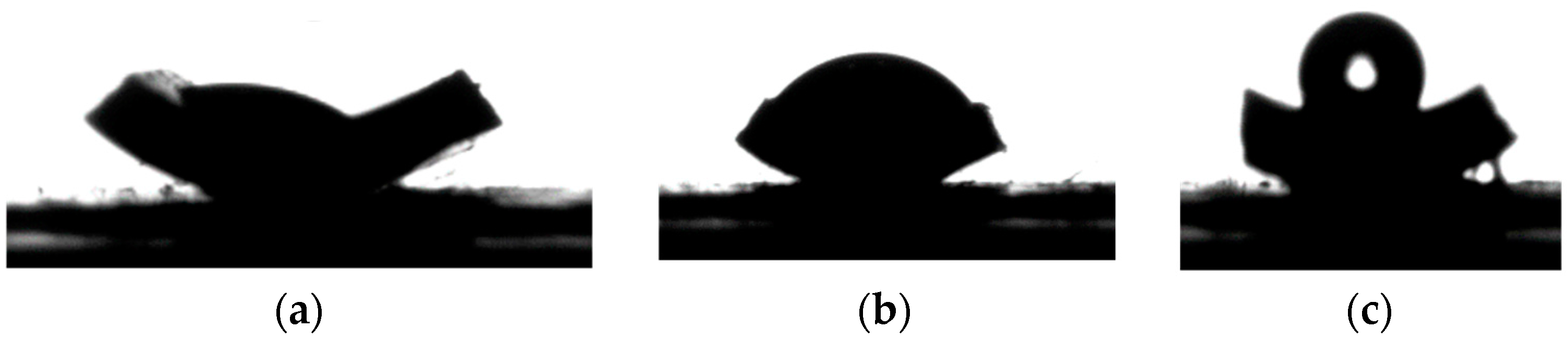
Hydrophobic membranes with better wetting resistance were produced after the growth of hydrophobic floss on the MOF functionalized surface. The LEP value of the newly developed membrane increased from 0 to 3 bars.
(4)
The VMD performance was improved through the optimization of reaction time for the second MOF growth phase. A shorter reaction duration results in a looser MOF layer, thus the higher permeation flux. The minimum reaction time for the second MOF growth phase was about 1 h. A further shortening the reaction time would lead to membrane defects.

Acknowledgment

This research was funded by the Singapore National Research Foundation under its Energy Innovation Research Program for the project entitled, “Using Cold Energy from Re-gasification of Liquefied Natural Gas (LNG) for Novel Hybrid Seawater Desalination Technologies” (grant number: R-279-000-456-279). We would also gratefully thank Arkema Inc. for providing the PVDF material.

Author Contributions

Both authors contribute equally to this work.

Conflicts of Interest

The authors declare no conflict of interest.

Abbreviations

ATRattenuated total reflection
DIDeionized
EDXenergy dispersive spectrometry
FESEMfield emission scanning electron microscopy
FTIRFourier transform infrared
HKUSTHong Kong University of Science and Technology
LEPliquid entry pressure
MDmembrane distillation
MILMaterials of Institut Lavoisier
MOFMetal–Organic framework
NaClsodium chloride
PEpolyethylene
PMMApoly(methyl methacrylate)
PMIporometer
PPpolypropylene
PTFEpolytetrafluoro-ethylene
PVDFpolyvinylidene fluoride
SEMscanning electron microscope
THFtetrahydrofuran
VMDvacuum membrane distillation
XPSX-ray photoelectron spectroscopy
XRDX-ray diffraction
Amembrane area
cfNaCl concentrations in feed
cpNaCl concentrations in permeate
mmass of the permeate sample
Jwpermeation flux
ttime
βsalt rejection

References

  1. Long, J.R.; Yaghi, O.M. The pervasive chemistry of metal-organic frameworks. Chem. Soc. Rev. 2009, 38, 1213–1214. [Google Scholar] [CrossRef] [PubMed]
  2. Kitagawa, S.; Kitaura, R.; Noro, S.I. Functional porous coordination polymers. Angew. Chem. Int. Ed. 2004, 43, 2334–2375. [Google Scholar] [CrossRef] [PubMed]
  3. Khan, I.A.; Qian, Y.; Badshah, A.; Nadeem, M.A.; Zhao, D. Highly porous carbon derived from MOF-5 as a support of ORR electrocatalysts or fuel cells. ACS Appl. Mater. Interfaces 2016, 8, 17268–17275. [Google Scholar] [CrossRef] [PubMed]
  4. Jhung, S.H.; Lee, J.H.; Yoon, J.W.; Serre, C.; Ferey, G.; Chang, J.S. Microwave synthesis of chromium terephthalate MIL-101 and its benzene sorption ability. Adv. Mater. 2007, 19, 121–124. [Google Scholar] [CrossRef]
  5. Taylor, K.M.L.; Jin, A.; Lin, W. Surfactant-assisted synthesis of nanoscale gadolinium metal-organic frameworks for potential multimodal imaging. Angew. Chem. Int. Ed. 2008, 47, 7722–7725. [Google Scholar] [CrossRef] [PubMed]
  6. Cho, W.; Lee, H.J.; Choi, G.; Choi, S.; Oh, M.J. Dual changes in conformation and optical properties of fluorophores within a metal-organic framework during framework construction and associated sensing event. Am. Chem. Soc. 2014, 136, 12201–12204. [Google Scholar] [CrossRef] [PubMed]
  7. Nalaparaju, A.; Zhao, X.S.; Jiang, J.W. Biofuel purification by pervaporation and vapor permeation in metal-organic frameworks: A computational study. Energy Environ. Sci. 2011, 4, 2107–2116. [Google Scholar] [CrossRef]
  8. Zhao, Y.; Seredych, M.; Zhong, Q.; Bandosz, T.J. Superior performance of copper based MOF and aminated graphite oxide composites as CO2 adsorbents at room temperature. ACS Appl. Mater. Interfaces 2016, 5, 4951–4959. [Google Scholar] [CrossRef] [PubMed]
  9. Chen, B.; Ockwig, N.W.; Millward, A.R.; Contreras, D.S.; Yaghi, O.M. High H2 adsorption in a microporous metal-organic framework with open metal sites. Angew. Chem. Int. Ed. 2005, 44, 4745–4749. [Google Scholar] [CrossRef] [PubMed]
  10. Latroche, M.; Surble, S.; Serre, C.; Mellot-Draznieks, C.; Llewellyn, P.L.; Lee, J.H.; Chang, J.S.; Sung, H.J.; Ferey, G. Hydrogen storage in the giant-pore metal-organic frameworks MIL-100 and MIL101. Angew. Chem. Int. Ed. 2006, 4, 8227–8231. [Google Scholar] [CrossRef] [PubMed]
  11. Ferey, G. Hybrid porous solids: Past, present, future. Chem. Soc. Rev. 2008, 37, 191–214. [Google Scholar] [CrossRef] [PubMed]
  12. Keskin, S.; Sholl, D.S. Selecting metal organic frameworks as enabling materials in mixed matrix membranes for high efficiency natural gas purification. Energy Environ. Sci. 2010, 3, 343–351. [Google Scholar] [CrossRef]
  13. Yang, T.X.; Xiao, Y.C.; Chung, T.S. Poly-/Metal-benzimidazole nano-composite membranes for hydrogen purification. Energy Environ. Sci. 2011, 4, 4171–4180. [Google Scholar] [CrossRef]
  14. Jeazet, H.B.T.; Staudt, C.; Janiak, C. Factors controlling successful formation of mixedmatrix gas separation materials. Dalton Trans. 2012, 41, 14003–14027. [Google Scholar]
  15. Chung, T.S.; Jiang, L.Y.; Li, Y.; Kulprathipanja, S. Mixed matrix membranes (MMMs) comprising organic polymers with dispersed inorganic fillers for gas separation. Prog. Polym. Sci. 2007, 32, 483–507. [Google Scholar] [CrossRef]
  16. Mahajan, R.; Koros, W.J. Factors controlling successful formation of mixedmatrix gas separation materials. Ind. Eng. Chem. Res. 2000, 39, 2692–2696. [Google Scholar] [CrossRef]
  17. Basu, S.; Cano-Odena, A.; Vankelecom, I.F.J. Asymmetric Matrimid@/[Cu3(BTC)2] mixed-matrix membranes for gas separations. J. Membr. Sci. 2010, 362, 478–487. [Google Scholar] [CrossRef]
  18. Zacher, D.; Shekhah, O.; Woll, C.; Fischer, R.A. Thin films of metal-organic frameworks. Chem. Soc. Rev. 2009, 38, 1418–1429. [Google Scholar] [CrossRef] [PubMed]
  19. Ben, T.; Lu, C.; Pei, C.; Xu, S.; Qiu, S. Polymer-supported and free-standing metal-organic framework membrane. Chem. Eur. J. 2012, 18, 10250–10253. [Google Scholar] [CrossRef] [PubMed]
  20. Tan, T.T.Y.; Reithofer, M.R.; Chen, E.Y.; Menon, A.G.; Hor, T.S.A.; Xu, J.; Chin, J.M. Tuning omniphobicity via morphological control of metal-organic framework functionalized surfaces. J. Am. Chem. Soc. 2013, 135, 16272–16275. [Google Scholar] [CrossRef] [PubMed]
  21. Saeki, D.; Nagashima, Y.; Sawada, I.; Matsuyama, H. Effect of hydrophobicity of polymer materials used for water purification membranes on biofilm formation dynamics. Colloids Surf. A Physicochem. Eng. Asp. 2016, 506, 622–628. [Google Scholar] [CrossRef]
  22. Karkhanechi, H.; Rajabzadeh, S.; Nicolo, E.D.; Usuda, H.; Shaikh, A.R.; Matsuyama, H. Preparation and characterization of ECTFE hollow fiber membranes via thermally induced phase separation (TIPS). Polymer 2016, 97, 515–524. [Google Scholar] [CrossRef]
  23. Hou, D.; Wang, J.; Sun, X.; Ji, Z.; Luan, Z. Preparation and properties of PVDF composite hollow fiber membranes for desalination through direct contact membrane distillation. J. Membr. Sci. 2012, 405–406, 185–200. [Google Scholar] [CrossRef]
  24. Rafat, M.; De, D.; Khulbe, K.C.; Nguyen, T.; Matsuura, T. Surface characterization of hollow fiber membranes used in artificial kidney. J. Appl. Polym. Sci. 2006, 101, 4386–4400. [Google Scholar] [CrossRef]
  25. Herminghaus, S. Roughness-induced non-wetting. Europhys. Lett. 2000, 52, 165–170. [Google Scholar] [CrossRef]
  26. Gao, X.; Jiang, L. Water-repellent legs of water striders. Nature 2004, 432, 36. [Google Scholar] [CrossRef] [PubMed]
  27. Tuteja, A.; Choi, W.; Ma, M.; Mabry, J.M.; Mazzella, S.A.; Rutledge, G.C.; McKinley, G.H.; Cohen, R.E. Designing superoleophobic surfaces. Science 2007, 318, 1618–1622. [Google Scholar] [CrossRef] [PubMed]
  28. Chin, J.M.; Chen, E.Y.; Menon, A.G.; Tan, H.Y.; Hor, A.T.S.; Schreyer, M.K.; Xu, J. Tuning the aspect ratio of NH2-MIL-53(Al) microneedles and nanorods via coordination modulation. Cryst. Eng. Commun. 2013, 15, 654–657. [Google Scholar] [CrossRef]
  29. Shi, G.M.; Chung, T.S. Thin film composite membranes on ceramic for pervaporation dehydration of isopropanol. J. Membr. Sci. 2013, 448, 34–43. [Google Scholar] [CrossRef]
  30. Li, B.; Sirkar, K.K. Novel membrane and device for vacuum membrane distillation-based desalination process. J. Membr. Sci. 2005, 257, 60–75. [Google Scholar] [CrossRef]
  31. Tomaszewska, M. Membrane distillation. Environ. Prot. Eng. 1999, 25, 37–47. [Google Scholar]
  32. Garcia-Payo, M.C.; Izquierdo-Gil, M.A.; Fernandez-Pineda, C. Wetting study of hydrophobic membranes via liquid entry pressure measurements with aqueous alcohol solutions. J. Colloid Interface Sci. 2000, 230, 420–431. [Google Scholar] [CrossRef] [PubMed]
  33. Song, Z.W.; Jiang, L.Y. Optimization of morphology and performance of PVDF hollow fiber for direct contact membrane distillation using experimental design. Chem. Eng. Sci. 2013, 101, 130–143. [Google Scholar] [CrossRef]
  34. Zhang, J.; Li, J.D.; Duke, M.; Hoang, M.; Xie, Z.; Groth, A.; Tun, C.; Gray, S. Influence of module design and membrane compressibility on VMD performance. J. Membr. Sci. 2013, 442, 31–38. [Google Scholar] [CrossRef] [Green Version]
  35. Sukitpaneenit, P.; Chung, T.S. Molecular design of the morphology and pore size of PVDF hollow fiber membranes for ethanol-water separation employing the modified pore-flow concept. J. Membr. Sci. 2011, 374, 67–82. [Google Scholar] [CrossRef]
  36. Zuo, J.; Bonyadi, S.; Chung, T.S. Exploring the potential of commercial polyethylene membranes for desalination by membrane distillation. J. Membr. Sci. 2016, 497, 239–247. [Google Scholar] [CrossRef]
  37. Kujawski, W.; Kujawa, J.; Wierzbowska, E.; Cerneaux, S.; Bryjak, M.; Kujawski, J. Influence of hydrophobization conditions and ceramic membranes pore size on the properties in vacuum membrane distillation of water-organic solvent mixtures. J. Membr. Sci. 2016, 499, 442–451. [Google Scholar] [CrossRef]
  38. Lawson, K.W.; Lloyd, D.R. Membrane distillation (review). J. Membr. Sci. 1997, 124, 1–25. [Google Scholar] [CrossRef]
  39. Francis, L.; Ghaffour, N.; Alsaadi, A.S.; Nunes, S.P.; Amy, G.L. Performance evaluation of the DCMD desalination process under bench scale and large scale module operating conditions. J. Membr. Sci. 2014, 455, 103–112. [Google Scholar] [CrossRef]
  40. Alsaadi, A.; Francis, L.; Amy, G.L.; Ghaffour, N. Experimental and theoretical analyses of temperature polarization effect in vacuum membrane distillation. J. Membr. Sci. 2014, 471, 138–148. [Google Scholar] [CrossRef]
  41. Fan, H.; Peng, Y. Application of PVDF membranes in desalination and comparison of the VMD and DCMD processes. Chem. Eng. Sci. 2012, 79, 94–102. [Google Scholar] [CrossRef]
  42. Wang, P.; Chung, T.S. A new-generation asymmetric multi-bore hollow fiber membrane for sustainable water production via vacuum membrane distillation. Environ. Sci. Technol. 2013, 47, 6272–6278. [Google Scholar] [CrossRef] [PubMed]
  43. Ding, S.B.; Wang, W.; Qiu, L.G.; Yuan, Y.P.; Peng, F.M.; Jiang, X.; Xie, A.J.; Shen, Y.H.; Zhu, J.F. Surfactant-assisted synthesis of lanthanide metal-organic framework nanorods and their fluorescence sensing of nitroaromatic explosives. Mater. Lett. 2011, 65, 1385–1387. [Google Scholar] [CrossRef]
  44. Yun, S.K.; Kim, J.W.; Jung, M.J.; Nho, Y.C.; Kang, P.H.; Lee, Y.S. An XPS study of oxyfluorinated multiwalled carbon nano tubes. Carbon Lett. 2007, 8, 292–298. [Google Scholar] [CrossRef]
  45. Nanse, G.; Papirer, E.; Fioux, P.; Moguet, F.; Tressaud, A. Fluorination of carbon blacks: An X-ray photoelectron spectroscopy study: I. A literature review of XPS studies of fluorinated carbons. XPS investigation of some reference compounds. Carbon 1997, 35, 175–194. [Google Scholar] [CrossRef]
  46. Zuo, J.; Chung, T.S. Design and synthesis of a fluoro-silane amine monomer for novel thin film composite membranes to dehydrate ethanol via pervaporation. J. Mater. Chem. A 2013, 1, 9814–9826. [Google Scholar] [CrossRef]
  47. Mihaly, J.; Sterkel, S.; Ortner, H.M.; Kocsis, L.; Hajba, L.; Furdyga, E.; Mink, J. FTIR and FT-Raman spectroscopic study on polymer based high pressure digestion vessels. Croat. Chem. Acta 2006, 79, 497–501. [Google Scholar]
  48. El-Bourawi, M.S.; Ding, Z.; Ma, R.; Khayet, M. A framework for better understanding membrane distillation separation process. J. Membr. Sci. 2006, 285, 4–29. [Google Scholar] [CrossRef]
  49. Zhang, J.; Li, J.D.; Duke, M.; Xie, Z.; Gray, S. Performance of asymmetric hollow fiber membranes in membrane distillation under various configurations and vacuum enhancement. J. Membr. Sci. 2010, 362, 517–528. [Google Scholar] [CrossRef] [Green Version]
  50. Chandavasu, C.; Xanthos, M.; Sirkar, K.K.; Gogos, C.G. Fabrication of microporous polymeric membranes by melt processing of immiscible blends. J. Membr. Sci. 2003, 211, 167–175. [Google Scholar] [CrossRef]
  51. Maab, H.; Francis, I.; Al-saadi, A.; Aubry, C.; Ghaffour, N.; Amy, G.; Nunes, S.P. Synthesis and fabrication of nanostructured hydrophobic polyazole membranes for low-energy water recovery. J. Membr. Sci. 2012, 423–424, 11–19. [Google Scholar] [CrossRef]
  52. Tomaszewska, M. Preparation and properties of flat-sheet membranes from poly(vinylidene fluoride) for membrane distillation. Desalination 1996, 104, 1–11. [Google Scholar] [CrossRef]
  53. Khayet, M.; Matsuura, T. Preparation and characterization of polyvinylidene fluoride membranes for membrane distillation. Ind. Eng. Chem. Res. 2001, 40, 5710–5718. [Google Scholar] [CrossRef]
  54. Tang, N.; Jia, Q.; Zhang, H.; Li, J.; Cao, S. Preparation and morphological characterization of narrow pore size distributed polypropylene hydrophobic membranes for vacuum membrane distillation via thermally induced phase separation. Desalination 2010, 256, 27–36. [Google Scholar] [CrossRef]
  55. Figoli, A.; Simone, S.; Criscuoli, A.; Al-Jlil, S.A.; Al Shabouna, F.S.; Al-Romaih, H.S.; Di Nicolo, E.; Al-harbi, O.A.; Drioli, E. Hollow fivers for seawater desalination from blends of PVDF with different molecular weights: Morphology, properties and VMD performance. Polymer 2014, 55, 1296–1306. [Google Scholar] [CrossRef]
  56. Zhang, J.W.; Fang, H.; Wang, J.W.; Hao, L.Y.; Xu, X.; Chen, C.S. Preparation and characterization of silicon nitride hollow fiber membranes for seawater desalination. J. Membr. Sci. 2014, 450, 197–206. [Google Scholar] [CrossRef]
  57. Sun, A.C.; Kosar, W.; Zhang, Y.; Feng, X. Vacuum membrane distillation for desalination of water using hollow fiber membranes. J. Membr. Sci. 2014, 455, 131–142. [Google Scholar] [CrossRef]
  58. Wang, J.W.; Li, L.; Zhang, J.W.; Xu, X.; Chen, C.S. β-Sialon ceramic hollow fiber membranes with high strength and low thermal conductivity for membrane distillation. J. Eur. Ceram. Soc. 2016, 36, 59–65. [Google Scholar] [CrossRef]
Figure 1. The steps to prepare metal–organic framework (MOF)-functionalized hydrophobic membranes.
Water 08 00586 g001
Figure 2. Schematic illustration of the lab-scale setup for liquid entry pressure (LEP) measurements.
Water 08 00586 g002
Figure 3. Surface morphology of (a) outer surface and (b) inner surface of the pristine ceramic tube; (c) inner surface of the first growth tube.
Water 08 00586 g003
Figure 4. Surface morphology of the second growth tubes from (a) aluminum nitrate and (b) aluminum acetylacetonate sources.
Water 08 00586 g004
Figure 5. Energy dispersive spectrometry (EDX) element distributions on the crystals grown from (a) aluminum nitrate and (b) aluminum acetylacetonate sources.
Water 08 00586 g005
Figure 6. The reaction mechanism to form the NH2-MIL-53(Al) framework. MIL: material from Institut Lavoisier.
Water 08 00586 g006
Figure 7. The XRD (X-ray diffraction) patterns of pristine alumina membrane, second growth tube from aluminum acetylacetonate and second growth tube from aluminum nitride.
Water 08 00586 g007
Figure 8. The C1s X-ray photoelectron spectroscopy (XPS) spectra of the pristine alumina membrane, second growth tube from aluminum acetylacetonate and hydrophobic membrane.
Water 08 00586 g008
Figure 9. The Fourier transform infrared (FTIR) spectra of the second growth tube from aluminum acetylacetonate and hydrophobic membrane.
Water 08 00586 g009
Figure 10. Pore size distributions of the three membranes: (a) pristine; (b) second growth tube from aluminum acetylacetonate and (c) with hydrophobic floss.
Water 08 00586 g010
Figure 11. The water contact angles of the three membranes: (a) pristine (b) second growth tube from aluminum acetylacetonate and (c) with hydrophobic floss.
Water 08 00586 g011
Table 1. Vacuum membrane distillation (VMD) performance of MOF membranes prepared from different aluminum sources.
MembraneSecond MOF Growth Al SourceSecond MOF Growth Time (h)VMD Flux at 60 °C (L/m2-h)
Final hydrophobic membraneAluminum nitrate50Leak
Final hydrophobic membraneAluminum acetylacetonate506.2
Table 2. Liquid entry pressures (LEP) of membranes before and after the hydrophobic treatment.
MembraneSecond MOF Growth Time (h)Hydrophobic Floss GrowthLEP (Bar)
Second growth tube50No0
Second growth tube50Yes3
Table 3. The effect of second MOF growth duration on VMD performance.
MembraneSecond MOF Growth Time (h)VMD Flux at 50 °C (L/m2-h)VMD Flux at 60 °C (L/m2-h)
Final hydrophobic membrane504.56.2
Final hydrophobic membrane245.18.4
Final hydrophobic membrane59.617.7
Final hydrophobic membrane116.732.3
Final hydrophobic membrane0.523.9Leak
Table 4. A comparison of VMD performance with literature data for seawater desalination.
AuthorMembraneYearFeedFeed Temperature (°C)Flux (L/m2-h)
Khayet and Matsuura [53]PVDF flat sheet2001Pure water2517.0
Tang et al. [54]PP flat sheet20103 wt % NaCl7024.8
Alsaadi et al. [40]PTFE flat sheet2014Seawater6012.0
Figoli et al. [55]PVDF hollow fiber20143.5 wt % NaCl5022.1
Zhang et al. [56]Si3N4 hollow fiber20144 wt % NaCl8028.3
Sun et al. [57]PVDF hollow fiber2014Pure water801.9
Wang et al. [58]β-Sialon ceramic hollow fiber20162 wt % NaCl606.7
This workMOF-functionalized alumina tube20163.5 wt % NaCl6032.3
Notes: PVDF: polyvinylidene fluoride; PP: polypropylene; PTFE: polytetrafluoro-ethylene.

