Article

Assessment of Pattern and Shape Symmetry of Bilateral Normal Corneas by Scheimpflug Technology

by
Francisco Cavas-Martínez
1,*,
David P. Piñero
2,
Daniel G. Fernández-Pacheco
1,
Jorge Mira
1,
Francisco J. F. Cañavate
1 and
Jorge L. Alió
3,4
1
Department of Graphical Expression, Technical University of Cartagena, 30202 Cartagena, Spain
2
Group of Optics and Visual Perception, Department of Optics, Pharmacology and Anatomy, University of Alicante, 03690 Alicante, Spain
3
Keratoconus Unit of Vissum Corporation Alicante, 03016 Alicante, Spain
4
Department of Ophthalmology, Miguel Hernández University of Elche, 03202 Alicante, Spain
*
Author to whom correspondence should be addressed.
Symmetry 2018, 10(10), 453; https://doi.org/10.3390/sym10100453
Submission received: 31 July 2018 / Revised: 5 September 2018 / Accepted: 19 September 2018 / Published: 1 October 2018
(This article belongs to the Special Issue Applications Based on Symmetrical Characteristics of the Human Body)

Abstract

:
Purpose: The aim of this study was to assess bilateral symmetry in normal fellow eyes by using optical and geometric morphometric parameters. Methods: All participants underwent complete biocular examinations. Scheimpflug tomography data from 66 eyes of 33 patients were registered. The interocular symmetry was based on five patterns: morphogeometric symmetry, axial symmetry at the corneal vertex, angular-spatial symmetry, direct symmetry (equal octants), and enantiomorphism (mirror octants). Results: No statistically significant differences were found between right and left eyes in corneal morphogeometric (p ≥ 0.488) and aberrometric parameters (p ≥ 0.102). Likewise, no statistically significant differences were found in any of the axial symmetry parameters analyzed (p ≥ 0.229), except in the surface rotation angle beta (p = 0.102) and translation coordinates X0 and Y0 (p < 0.001) for the anterior corneal surface, and the rotation angle gamma (p < 0.001) for the posterior surface. Similarly, no statistically significant differences were identified for direct symmetry (p ≥ 0.20) and enantiomorphism (p ≥ 0.75), except for some elevation data in the posterior surface (p < 0.01). Conclusions: The level of symmetry of both corneas of a healthy individual is high, with only some level of disparity between fellow corneas in rotation and translation references. Abnormalities in this pattern of interocular asymmetry may be useful as a diagnostic tool.

1. Introduction

The human body’s structure is symmetrically bilateral along the median sagittal plane, which allows it to work more efficiently [1,2]. Analyzing bilateral symmetry from the perspective of morphologic characterization has proven interesting to diagnose diseases [3,4,5] and to detect pathologic anomalies [6].
In the human eye, interocular symmetry is a natural property that can help to distinguish any abnormality in bilateral eyes. This symmetry can be analyzed from several viewpoints; e.g., from an optical viewpoint, symmetry can be defined by the visual axis, being symmetric to the nose–chin axis toward the nasal visual field [7], which implies that the horizontal field of vision dominates the vertical one.
The cornea is a fundamental part of the eye, whose anatomical location is easily accessible via noninvasive clinical diagnostic techniques. Thus, studying the properties of intracorneal symmetry can help to define bilateral abnormalities in normal fellow eyes.
The first study about corneal symmetry demonstrated that bilateral symmetry dominates the median sagittal plane versus the other plane orientations [8]. Li et al. [9] studied bilateral symmetry using biometric parameters and reported that central cornea pachymetry parameters better characterize corneal asymmetry. Other authors have analyzed symmetry from the optical viewpoint [10] and concluded that symmetry is independent of anisometropia. Thus, it would be interesting to propose a pattern to analyze bilateral symmetry by combining morphometric and optical parameters.
Several studies have reported on bilateral symmetry in normal eyes using the parameters measured by corneal tomography [11,12,13,14,15]. These studies demonstrated a certain degree of symmetry between fellow eyes, but their scope was variable as they resorted to different measuring methods and equipment, which suggests a need to search for a primary data source that is common to different commercial solutions.
Corneal tomography equipment based on combining the Scheimpflug principle with Placido’s discs have proven to be reliable to perform corneal topography [16], as it provides very exact and repeatable measurements [17]. Thus, this type of equipment is widespread in clinical practice for evaluating patients’ visual quality [18], planning surgery [19], and building numerical models [20]. By the aid of a vision algorithm, this equipment obtains so-called raw data during the preprocessing phase [21], which is a primary dataset from mapping the contours of corneal surfaces. From these data, different models can be generated to predict the response to invasive [22,23,24] and noninvasive [20,25,26] clinical treatments. Our research group validated the use of such raw data to create a three-dimensional (3D) model of the cornea and subsequently analyze it geometrically to detect corneal diseases [27,28,29].
Very few works have evaluated symmetry using raw data. Bao et al. [8] applied a model to study bilateral symmetry in the apex. However, the apex is not easy to identify in a discrete set of spatial points, because a continuous surface in the space is required to locate this point, so it is suggested to seek another point that can be located in the primary dataset. Xiao et al. [30] evaluated the repeatability of using raw data by measuring misalignment among successive cornea measurements, concluding that this remained stable among the taken measurements. These results coincide with those from other authors [31] who validated the same data for healthy corneas with the iterative closest point algorithm. Thus, raw data are valid and repeatable and can be used to analyze bilateral symmetry between fellow corneas.
The natural symmetry between fellow corneas can be measured by direct transformation with positioning or a mirror. However, the existing results are contradictory. Some authors conducted studies with healthy corneas and reported that neither of the two symmetries predominated [32], while others indicated that mirror symmetry predominates in relation to astigmatism axes [11]. Nevertheless, these studies do not inform about the percentage of each symmetry’s prevalence, which tells us that the spatial region to measure symmetry is not sensitive enough to characterize the prevalence of one over the other.
In this context, a more in-depth understanding of the patterns and types of bilateral symmetry between healthy corneas is essential, and as far as we know, there are no thorough studies on the 3D corneal shape that provide enough information to evaluate symmetry between fellow eyes taking into account spatial and independent parameters of the cornea’s intrinsic geometry. We believe that acquiring more knowledge about the distribution and variation of geometric patterns between fellow corneas can be applied for a variety of clinical purposes; for instance, to optimize the geometry of corneal implants by defining the patterns that affect both their laterality and orientation compared to interocular asymmetry, to operate on strabismus, or to predict an eye’s refraction after operating on cataracts [7].
Bearing all this in mind, this new study aims to evaluate bilateral symmetry by defining five patterns: morphogeometric symmetry, axial symmetry at the corneal vertex, angular-spatial symmetry, direct symmetry, and enantiomorphism. These patterns characterize, both locally and globally, the 3D corneal shape with the aid of some parameters, and allows determination of the normal tolerance limits for the level of interocular symmetry when the values fall within the normal range.

2. Materials and Methods

2.1. Study Participants and Examination Protocol

This was a prospective case series study that included both eyes of 33 patients ranging in age from 11 to 63 years. The inclusion criteria were that patients had two healthy eyes and no previous ocular surgery. The exclusion criteria were previous ocular surgery, active systemic disease, presence of conjunctival or corneal scars or opacities, dry eye, and active ocular disease. This study was conducted at the Vissum Corporation (a center affiliated with Miguel Hernández University of Elche, Spain), and was approved by the university’s Clinical Research Ethics Committee. Written consent was obtained from the patients before being included in the study. The study was performed in accordance with the ethical standards of the Declaration of Helsinki (seventh revision, October 2013, Fortaleza, Brazil).
A complete eye examination was performed in all patients, which included anamnesis, measurement of uncorrected and corrected distance visual acuity (UDVA and CDVA, respectively), manifest refraction, slit-lamp biomicroscopy, and corneal topography obtained with the Sirius system (CSO, Firenze, Italy). During the process of generating the corneal topographies and in the preprocessing stage, the Sirius system allows raw data to be exported in comma-separated values (CSV) format, which is the format of the files used herein. Moreover, these files can be obtained from other corneal topographers [20,22,23,24,25,26], all of them based on the Scheimpflug principle. Therefore, the analysis proposed in this study is compatible with and independent of the commercial equipment used.

2.2. Data Acquisition

For the present study, we defined a protocol to acquire data, which consisted in taking 6 consecutive measurements per patient according to the OD, OS, OD, OS, OD, OS sequence (OD, right eye; OS, left eye). All measurements were taken by an experienced optometrist during the same clinical session. For each measurement, the patient was aligned and positioned in relation to the equipment being used according to its quality measurement acquisition index (CSO, Florence, Italy). From all measurements taken for each cornea per patient, the selected measurement was free of extrinsic errors and presented the best quality measurement acquisition index [27,28,29].

2.3. Methods

The intracorneal symmetry analysis makes sense if differences in size are removed among all the corneas that form the study. For this reason, in our study all the corneas were the same size (r = 4 mm) and to characterize them, we propose 5 patterns in an attempt to obtain intrinsic symmetry irrespective of corneal shape: morphogeometric symmetry, axial symmetry at the corneal vertex, angular-spatial symmetry, direct symmetry (equal octants), and enantiomorphism (mirror octants).

2.3.1. Morphogeometric Symmetry

Geometrically characterizing a biological structure with 2D/3D models is a well-established technique for clinical diagnostic purposes [33]. In the case of the cornea, our research work validated a method [27,28,29] to generate a 3D model using computer-aided design (CAD) techniques allowing corneal shape to be characterized for detecting diseases. We used some morphogeometric variables (Table 1) to characterize the symmetry between the right (OD) and left (OS) eyes (Figure 1).
Additionally, in this pattern we considered optical and topographic variables [16] obtained from the Sirius equipment as well as clinical variables, such as visual acuity and manifest refraction. These variables allow us to indirectly characterize corneal curvature, because variation in the geometry of corneal curvature affects a patient’s visual quality, and therefore optical capacity. Considered variables are: spherical equivalent (SE), corrected distance visual acuity (CDVA), corneal asphericity for a diameter of 4.5 mm (Q4.5), corneal asphericity for a diameter of 8 mm (Q8), high-order aberration (HOA), root mean square (RMS) and spherical aberration (SA) calculated for a 6 mm pupil, minimum corneal thickness (MCT), central corneal thickness (CCT), and corneal volume (CV).

2.3.2. Axial Symmetry at the Corneal Vertex

One way to characterize the bilateral symmetry between fellow corneas could be to individually analyze the alignment of each cornea in relation to its intrinsic symmetry axes, as they depend only on their own corneal shape, unlike the real axes of the reference coordinate system of the Sirius tomographer (CSO, Florence, Italy), which depends on the patient’s position (observation angle) in relation to the equipment used when taking measurements.
To this end, in this pattern we used Navarro’s model [34], which, by means of an algebraic transformation consisting of a rotation and translation matrix, allows the real Cartesian coordinate system of a corneal tomograph to be transformed into intrinsic-to-corneal-symmetry Cartesian coordinates.
This algebraic transformation is performed at the corneal apex in Navarro’s model. However, in the case of the corneal apex, which is the point of maximum curvature of the corneal surface, anterior and posterior apex points are not aligned with respect to any axis [28], as they depend only on their position in the corneal surface. Consequently, Navarro’s model applied in the apex cannot be applied to analyze corneal symmetry in our study, as anterior and posterior corneal surfaces are considered independently. On the other hand, the new tomographers based on Scheimpflug technology can differentiate between the corneal vertex and apex. In the case of the vertex, which is the point at which the corneal optic axis passes, the anterior and posterior vertex points are aligned in relation to this optic axis (Figure 2). Consequently, we propose to use the corneal vertex instead of the corneal apex in Navarro’s model to analyze symmetry, as corneal surfaces are considered independently.
In this symmetry pattern, we individually measure the alignment of each cornea in relation to its fellow by a transformation (rotation + translation) at the vertex (V) reference point of a cornea measured by a corneal tomograph (Cornea) on a perfect cornea (Cornea0) at the vertex reference point (V0) from corneal shape parameters (Table 2). The procedure takes place as follows:
  • Export raw data CSV files from Sirius. The original data in these files are polar coordinates. An algorithm (programmed in Matlab) is used to transform them into Cartesian coordinates [27,28,29].
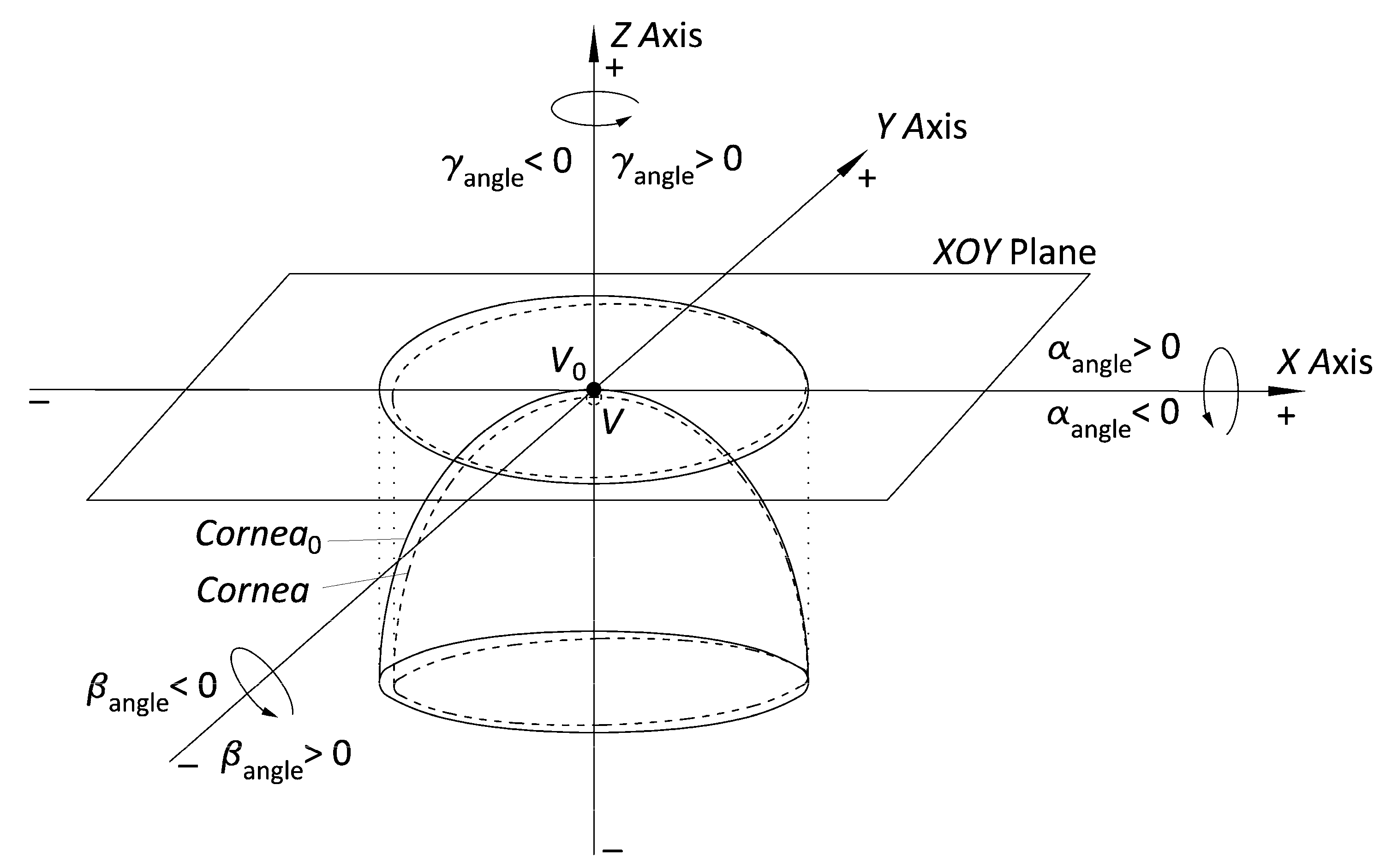
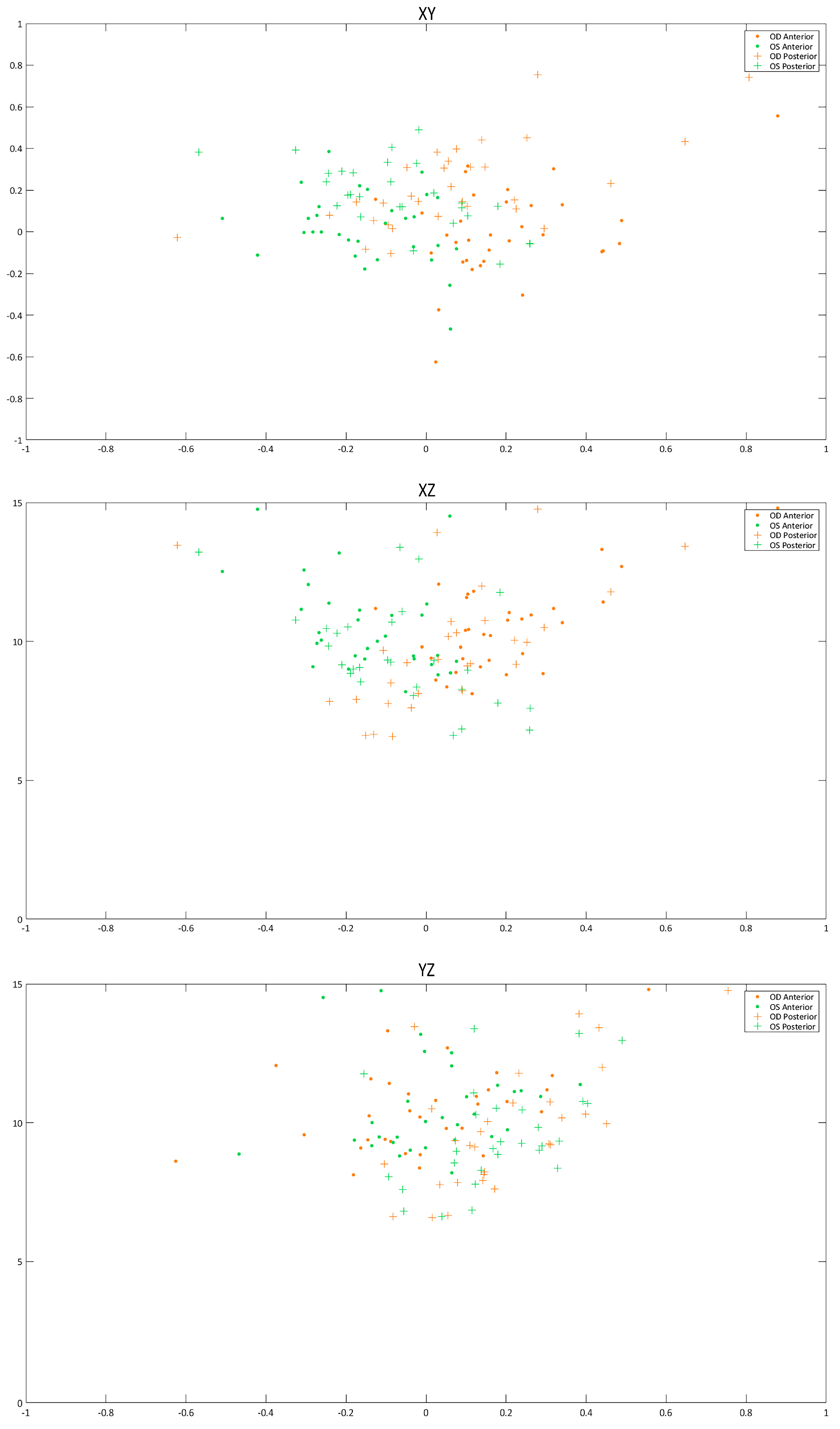
  • Adjust the point cloud to a general quadric model (ellipsoid) and subsequently transform into a perfect ellipsoid. With the help of some algorithms programmed in Matlab software that use the equations defined in Navarro’s model [34], we adjust the finite and discrete set of spatial data representative of the spatial surfaces (raw data) to an ellipsoid. Then, we perform the algebraic transformation with the matrix equations of the obtained ellipsoid into a perfect ellipsoid at the vertex reference point (V0), whose main axes are the 3 main position and orientation orthogonal axes in 3D space (Figure 2).

2.3.3. Angular-Spatial Symmetry

The symmetry of a biological structure can be characterized using the discrete landmarks method [35]. For bilateral symmetry, an attempt is made to identify a singular point at a relative position on the corneal surface area of the right eye and, by following the same protocol, to verify whether a symmetrical point exists at the same relative position on the left eye.
In this symmetry pattern, we propose identifying 2 singular points among the 256 points that comprise the projection of each Placido’s disc (radius ri) on the corneal surface area by its elevation Cartesian coordinate (Zi) and angular position (αi) on each ring. These singular points are those with a higher elevation coordinate (Zmax) with respect to the vertex of the Sirius reference system. In addition, in this work we also divide the spatial region into 8 octants to spatially identify each maximum and minimum per octant. This procedure is done as follows:
  • Export the raw data CSV files from Sirius. This procedure is the same as in point 1 of Section 2.3.2.
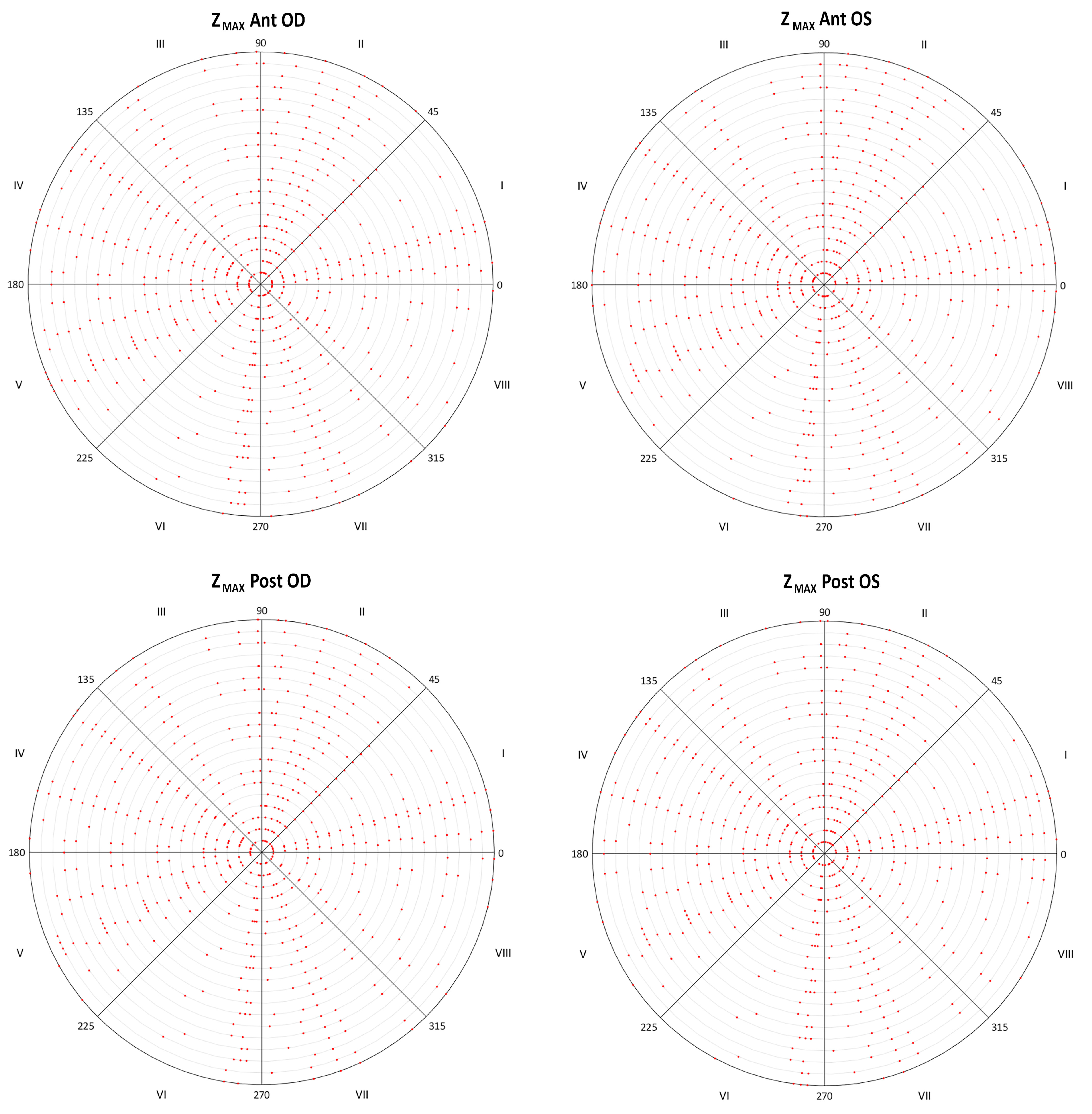
  • Identify the singular points for each ring by the elevation coordinate (Zi) and its angular position (αi). The Cartesian coordinate matrix (raw data) size is 20 × 256, where the 20 rows correspond to the projection of the 20 Placido’s discs (radius: 0, 0.2, 0.4, 0.6, 1, … 4 mm) on the corneal surface area, so they cover the corneal region for those corneas with a radius equal to 4 mm. Each matrix point i has a Cartesian elevation coordinate (Zi) and an angular position (αi) in relation to the projection ring of the Placido’s disc (anticlockwise). By the algorithm programmed in Matlab, we obtained the uppermost (Zmax) points in relation to the corneal vertex, and their angular positions (αZmax) in relation to the projection ring. This algorithm also helped us to identify each singular point with respect to the 8 defined octants.

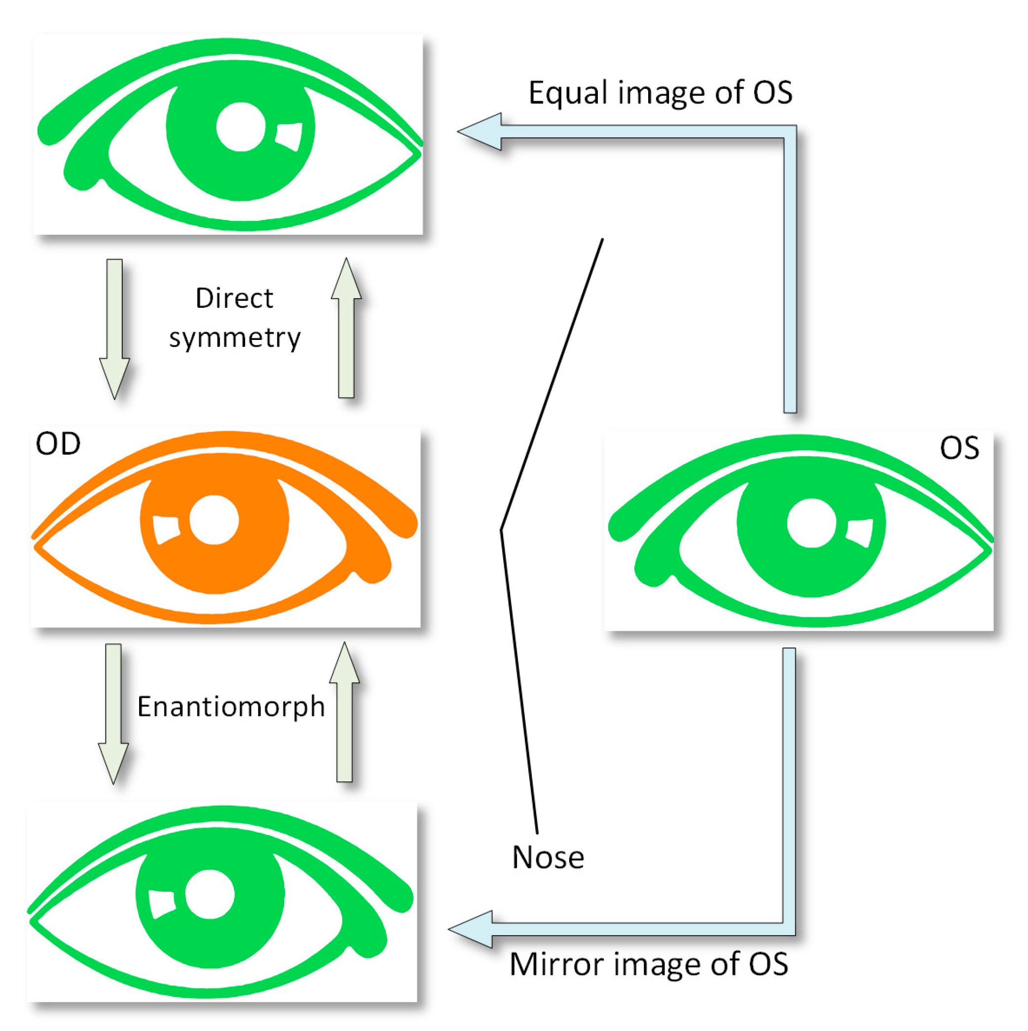
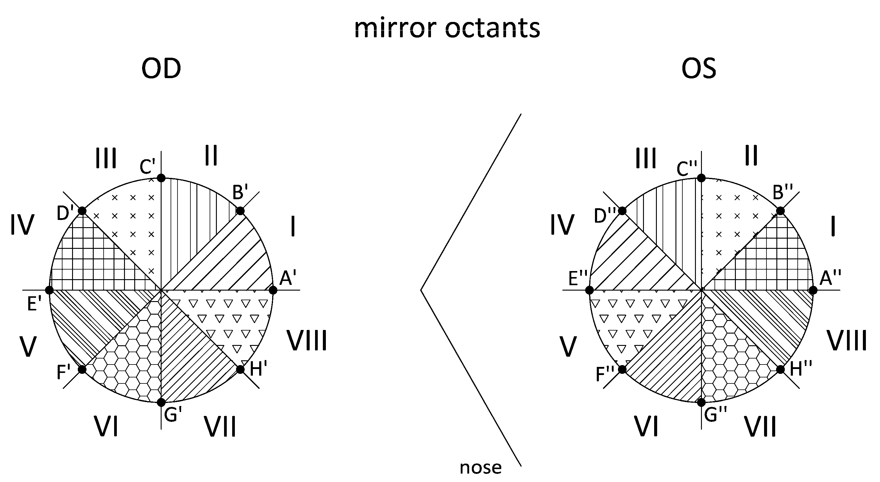
2.3.4. Direct Symmetry (Equal Octants) and Enantiomorphism (Mirror Octants)

Traditionally, the natural symmetry among biological structures has been studied by both position and mirror symmetry [7]. The idea in bilateral symmetry is to identify some points on the main axes of the surface areas of fellow corneas, and if it is the position type, with axes numerically equal, the difference between both points is zero. Although with mirror symmetry, the axes between corneas are not equal and their difference is not zero, but images are specular to one another (Figure 3).
In these symmetry patterns, we propose dividing the corneal region into 8 octants (I–VIII). The intersection of each axis that divides the space into octants, together with the projection of Placido’s discs on corneal surface areas, gives us 8 points on the right eye (X′) and 8 points on the left eye (X″). Therefore, the differences of position in the elevation coordinates between the obtained pairs of points of intersection (ZX′ZX″) are studied in this pattern (equal octants/mirror octants). The procedure for both symmetries is summarized as follows:
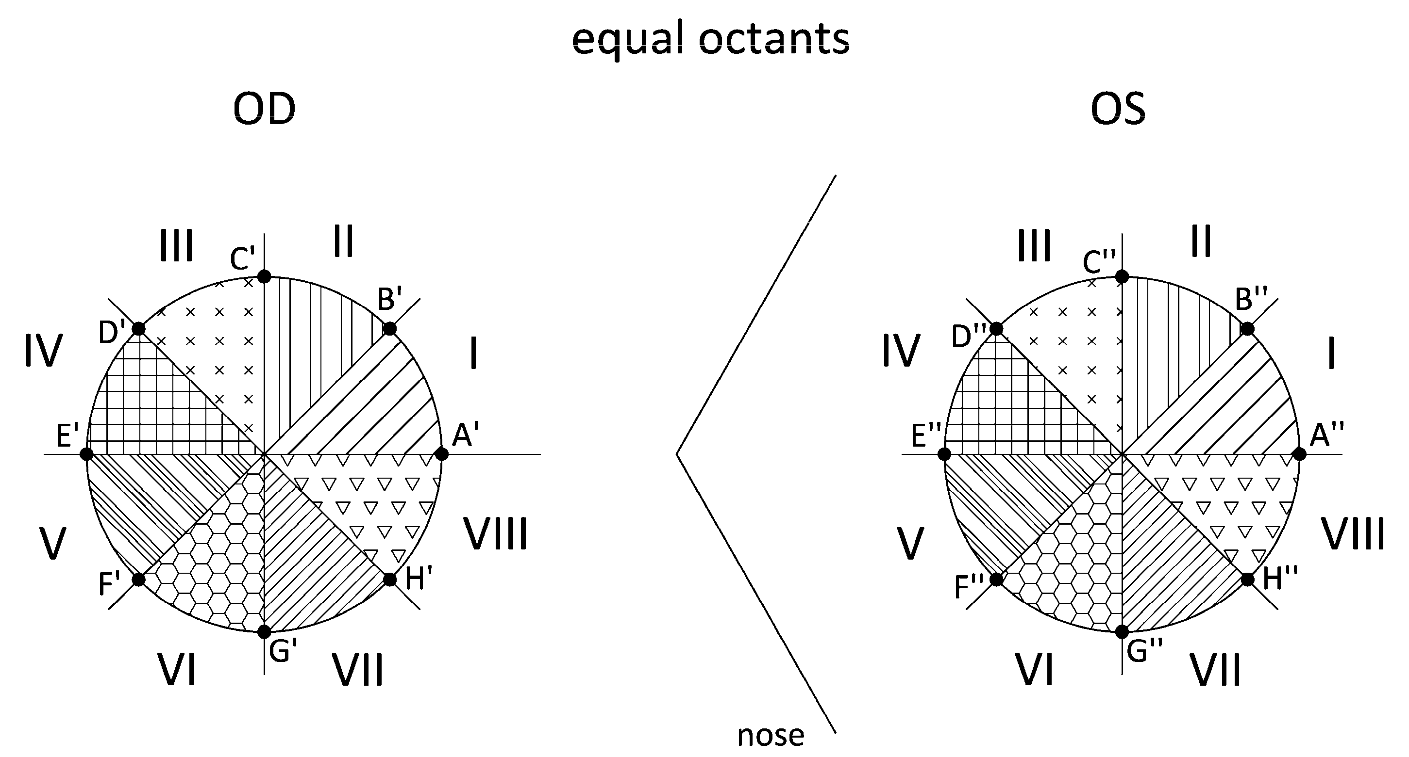
  • Export the raw data CSV files from Sirius. This procedure is the same as in point 1 of Section 2.3.3. Identify the intersection points (ZX′–OD/ZX″–OD) between the octant axes and the Placido’s discs. For the Cartesian coordinate matrix described in the previous patterns, the points placed on all 8 axes that divide the corneal region are identified. Using another algorithm programmed in Matlab, we identify the 8 points for each Placido’s disc by their angular position, which must coincide with the angles of the octant axes, and obtain the Cartesian elevation coordinates for the right eye (ZA′ZH′) and the left eye (ZA″ZH″) (Figure 4). Our study considered only the intersection points between the octant axes and the Placido’s discs for radius r = 1, 2, 3, and 4 mm.
  • Apply direct symmetry (equal octants). In this pattern, the 8 octants of the right eye and the left eye coincide (Figure 4). Using an algorithm programmed in Matlab, we calculated the differences between the elevation coordinates for each pair of points (Table 3).
  • Apply enantiomorph (mirror octants). In this pattern, the octants of the right eye do not coincide with the octants of the left eye. Instead, each right eye (OD) octant has a corresponding octant in the left eye (OS) via its specular image; that is, by its specular image, octant I-OD corresponds to octant IV-OS (Figure 5). As in the previous point, by means of another algorithm programmed in Matlab, the differences between the elevation coordinates for each pair of points are calculated (Table 3).

2.4. Statistical Analysis

SPSS statistics software package version 15.0 (IBM, Armonk, NY, USA) was used for the statistical analysis. Normality of all data was checked by means of the Kolmogorov–Smirnov test. Comparison between measurements obtained in right and left eyes was performed using paired Student’s t if variables were normally distributed or the Wilcoxon ranked sum test if one or more variables were not normally distributed. Differences were statistically significant when the associated p-value was <0.05. Furthermore, Pearson or Spearman correlation coefficients were calculated depending on whether or not the normality condition could be assumed to assess the relationships between different variables.

3. Results

The sample included a total of 66 eyes of 33 patients ranging in age from 11 to 63 years (mean: 37.4, SD: 14.5, median: 41.0), composed of 18 male patients (54.5%) and 15 female patients (45.5%).

3.1. Analysis of Morphogeometric Corneal Symmetry

In this pattern, bilateral symmetry is analyzed by optical and morphogeometric variables. Table 4 summarizes the visual, refractive, and corneal tomographic data of right and left eyes of the sample evaluated. As shown, no significant differences were found between right and left eyes for the main clinical parameters evaluated (p ≥ 0.102).
Regarding the morphogeometric variables obtained from the 3D corneal model, Table 5 summarizes the morphogeometric data obtained in the right and left eyes of the sample evaluated. A difference close to the limit of statistical significance between fellow eyes was found for variable Aant, with a trend toward higher values in left eyes (p = 0.055). No significant differences between right and left eyes were found for the rest of the morphogeometric parameters evaluated (p ≥ 0.488).

3.2. Analysis of Axial Symmetry at the Corneal Vertex

In the pattern of axial symmetry at the corneal vertex, measurements were taken individually on each area of each cornea to compare the symmetry between fellow corneas. Table 6 and Table 7 summarize the axial symmetry data for the anterior and posterior corneal surfaces in the group of right and left eyes of the evaluated sample.
For the anterior corneal surface, significant differences between right and left eyes were found for beta (p = 0.012), X0, and Y0 (p < 0.001) (Table 6).
For the posterior corneal surface, differences between right and left eyes were statistically significant for gamma angle (p = 0.004), with a trend toward more negative values in the left eye (Table 7).
The results also include the Cartesian coordinates of the vertex of corneal surfaces (anterior/posterior), expressed by translational displacements X0, Y0, Z0 (Figure 6). The vertex mean value (V) of both right and left eyes with normal corneas are located on the nasal and inferior-nasal sides of the vertex (V0) in anterior and posterior surface corneas (Cornea0, ellipsoid), respectively (Figure 6). These results provide further evidence of mirror symmetry relative to the median vertical plane YZ.
The analysis was extended to the angles of rotational displacement between the real Cartesian coordinate system (Cornea) of corneal tomograph and intrinsic-to-corneal-symmetry Cartesian coordinate system (Cornea0) (Figure 7). Angles α and β had similar distributions in bilateral corneas with the same angle signs in fellow corneas (Figure 7), indicating a high degree of direct symmetry (both rotated toward the nasal side) relative to the median vertical plane XY. Similar results were obtained for angle γ, although in this case the values for right and left corneas had opposite signs, indicating a high degree of mirror symmetry relative to the median vertical plane YZ.

3.3. Analysis of Angular-Spatial Symmetry

In the angular-spatial symmetry pattern, measurements can be taken in relation to singular points in a characteristic relative position on each (anterior/posterior) corneal surface area to compare the symmetry between fellow corneas. Table 8 summarizes the angular-spatial symmetry data for the anterior and posterior corneal surfaces in the right and left eyes of the evaluated sample. No significant differences between right and left eyes were detected for Zmax calculated for four circular areas with a radius of 1, 2, 3, and 4 mm (p ≥ 0.171). Likewise, Zmax in most cases was located in the same octants in the right and left eyes, as displayed in Figure 8.

3.4. Analysis of Direct Symmetry (Equal Octants) and Enantiomorphism (Mirror Octants)

In these natural symmetry patterns, measurements are taken in relation to the pairs of points (Table 3) for each (anterior/posterior) corneal surface area to compare the symmetry between the right and left corneas. Table 9 summarizes the results of the statistical analysis of the direct symmetry data. As shown, no statistically significant differences among equal octants of right and left eyes in the anterior corneal surface were found between central (1 mm) and mid-peripheral (4 mm) (p ≥ 0.77) areas. Indeed, these differences among equal octants were close to zero in most cases for all corneal areas analyzed. However, differences among some equal octants of right and left eyes (D′–D″, E′–E″, G′–G″, and H′–H″) in the posterior corneal surface were significantly higher in the mid-peripheral area compared to the central areas (p < 0.01).
Table 10 summarizes the results of the statistical analysis of the enantiomorphism data. As shown, no statistically significant differences among mirror octants of right and left eyes in the anterior corneal surface were found between central (1 mm) and mid-peripheral (4 mm) areas (p ≥ 0.75). Indeed, these differences were close to zero in most cases for all corneal areas analyzed. However, differences among some mirror octants of right and left eyes (B′–D″, D′–B″, E′–A″, F′–H″, and H′–F″) in the posterior corneal surface were significantly higher in the mid-peripheral area compared to the central areas (p ≤ 0.01).

4. Discussion

Several studies have been conducted to evaluate the level of interocular corneal symmetry in the normal healthy population by analyzing a great variety of parameters provided by different commercial devices used for such purpose [8,9,10,11,12,13,14,15,32,36,37,38,39]. Specifically, high levels of interocular symmetry have been reported in variables such as corneal curvature [9,10,12,37], central corneal thickness [9,13,37,38], anterior and posterior corneal elevation [10,12,38], corneal astigmatism [9,11,36,39], minimum corneal thickness [10,12,13], corneal aberrations [14], corneal diameter [15], corneal shape factor [37], and even some biomechanical metrics [40]. This is consistent with the results obtained in our sample, as we did not find significant differences between fellow eyes in corneal asphericity, aberrations, pachymetry, and volume. Therefore, good levels of interocular asymmetry were present in our sample in all these clinical parameters. However, it should be considered that they are not sufficient to characterize the real geometric and volumetric configuration of the cornea [28,29]. They are the result of previous processing of raw data obtained by tomographers and topographers, using approximations and general adjustments [16], without considering a specific analysis of the real interocular symmetry of corneal geometry. This may partly explain some contradictory findings reported in the peer-reviewed literature. For example, while some authors have reported high levels of mirror symmetry of the astigmatic axes of right and left eyes [9,11,36,39], others have not found this in healthy eyes [32]. In the current study, we investigated the level of interocular symmetry in a sample of healthy eyes by using different approaches to analyze this property. For this purpose, different mathematical analyses were done by directly processing the raw data provided by a commercially available and previously validated topographer [41]. Besides the comparison of conventional clinical variables between fellow eyes, a comparative analysis of differences in terms of morphogeometric configuration was also performed. This analysis was proposed by our research group as a tool to characterize the 3D configuration of the cornea, and it has been shown to be useful for the detection and evaluation of degenerative corneal conditions, such as keratoconus [27,28,29]. In our sample, we did not find significant differences between right and left eyes in any of the morphogeometric parameters described and validated by our research group, which suggests symmetry in terms of 3D configuration between fellow eyes. To this date, no work has studied this type of symmetry, including volumetric comparisons. Therefore, the fellow corneas of the healthy subjects seem to have similar volumes and 3D configurations. This is consistent with the results of previous studies reporting symmetry in terms of pachymetric data [9,11,13,36,37,38,39]. Specifically, Prakash et al. [13] observed that minimum corneal thickness points in fellow eyes tended to be symmetrical along the vertical midline. Future studies should be conducted to confirm whether this outcome is also found in anisometropic subjects.
Very few works have evaluated axial symmetry at the corneal vertex using raw data. We used the same methodology described by Bao et al. [8] to confirm whether we were able to obtain similar findings. We found the same trend of a nasal and inferior-nasal location of corneal apex in the anterior and posterior corneal surfaces in reference to the geometric center. Therefore, mirror symmetry was present concerning the position of the apex in the two surfaces of the cornea. This is in agreement not only with the study of Bao et al. [8], but also with other studies reporting the position of the apex using the processed data provided by commercially available topographers [42]. Besides the significant difference found between fellow eyes in X0 (different sign) confirming the presence of mirror symmetry relative to the median vertical plane YZ, a significant difference was also found in Y0, with mean values of opposite sign for the right and left eyes. This also confirms the presence of mirror symmetry relative to the median horizontal plane XZ. This last type of mirror symmetry was not found by Bao et al. [8], especially in the posterior corneal surface. One factor that potentially accounts for this is the difference between the devices used in their study and in the current study to characterize the posterior corneal surface [43]. This difference between devices may also explain the different trend reported by Bao et al. [8] in terms of rotational displacement angles. In our sample, significant differences between fellow eyes were found in beta angle for the anterior corneal surface and in gamma angle for the posterior corneal surface, with more negative values for the left eye.
Finally, we evaluated for the first time other types of corneal symmetry, including angular-spatial symmetry and direct and mirror symmetry, in terms of corneal elevation by octants. No significant differences were found in terms of Zmax and its position (defined by octants) between right and left eyes for the anterior corneal surface. For the posterior corneal surface, differences in octant position of Zmax were found between eyes, suggesting lower levels of symmetry. This was confirmed with the analysis of direct and mirror symmetry, obtaining significant differences between eyes in terms of corneal elevation in equal and mirror octants for different areas of analysis. However, differences in anterior corneal elevation between fellow eyes in equal and mirror octants were not statistically significant for different diameters, suggesting that both types of symmetry coexist in the anterior corneal surface. Although there was mirror symmetry in terms of apex position in anterior corneal surface, the geometric distribution is quite regular, leading to no significant differences in elevation between equal and mirror octants along the central and mid-peripheral corneal areas. This regularity of anterior corneal surface in contrast to the higher level of irregularity in the posterior corneal surface may be due to, among other factors, the potential effect of regularization of the eyelid during blinking [44]. In the posterior corneal surface, differences in the effect of intraocular pressure over the corneal structure may explain this lower level of symmetry by octants. Indeed, alterations in posterior corneal surface elevation and curvature have been proposed as efficient ways to detect incipient stages of corneal ectatic disorders, as the intraocular pressure may begin the deformation of the corneal geometry when the structure becomes weakened [45].

5. Conclusions

This study indicates the existence of mirror symmetry between fellow eyes in terms of apex position of the anterior and posterior corneal surfaces. Likewise, high levels of symmetry are present in elevation data of the anterior corneal surface, whereas some level of asymmetry is present in posterior corneal surface. From a morphogeometric point of view, a symmetric 3D configuration is present in fellow eyes of the same individuals.
Future studies should confirm the potential of this complete analysis of symmetry for the detection of corneal abnormalities or pathologies, such as the recognition of unilateral incipient corneal pathologies in which there is a loss of symmetry between both eyes, or the validation of unilateral transplantation techniques (partial or total) in which the transplanted cornea should keep the symmetry with its fellow cornea. Furthermore, it could be considered as an indirect means of evaluating biomechanical changes occurring in the corneal structure.

Author Contributions

F.C.-M., D.P.P. and D.G.F.-P. designed the experiments, which were later executed by J.M. and J.L.A. The analysis of the obtained data was performed by F.C.-M., F.J.F.C., and D.P.P. Finally, all authors contributed to the writing of the manuscript.

Funding

This publication has been carried out in the framework of the Thematic Network for Co-Operative Research in Health (RETICS), reference number RD16/0008/0012, financed by the Carlos III Health Institute–General Subdirection of Networks and Cooperative Investigation Centers (R&D&I National Plan 2013–2016) and the European Regional Development Fund (FEDER). The author David P. Piñero has been supported by the Ministry of Economy, Industry and Competitiveness of Spain within the program Ramón y Cajal, RYC-2016-20471.

Conflicts of Interest

The authors declare no conflict of interest.

References

  1. Hickox, L.J.; Ashby, B.M.; Alderink, G.J. Exploration of the validity of the two-dimensional sagittal plane assumption in modeling the standing long jump. J. Biomech. 2016, 49, 1085–1093. [Google Scholar] [CrossRef] [PubMed]
  2. Jayasuriya, S.A.; Liew, A.W.C.; Law, N.F. Symmetry plane detection in brain image analysis: A survey. Curr. Med. Imaging Rev. 2013, 9, 230–247. [Google Scholar] [CrossRef]
  3. Alterson, R.; Plewes, D.B. Bilateral symmetry analysis of breast mri. Phys. Med. Biol. 2003, 48, 3431–3443. [Google Scholar] [CrossRef] [PubMed]
  4. Chan, S.; Chen, J.H.; Li, S.; Chang, R.; Yeh, D.C.; Chang, R.F.; Yeh, L.R.; Kwong, J.; Su, M.Y. Evaluation of the association between quantitative mammographic density and breast cancer occurred in different quadrants. BMC Cancer 2017, 17, 274. [Google Scholar] [CrossRef] [PubMed]
  5. Navalho, M.; Resende, C.; Rodrigues, A.M.; Ramos, F.; Gaspar, A.; Pereira Da Silva, J.A.; Fonseca, J.E.; Campos, J.; Canhão, H. Bilateral mr imaging of the hand and wrist in early and very early inflammatory arthritis: Tenosynovitis is associated with progression to rheumatoid arthritis. Radiology 2012, 264, 823–833. [Google Scholar] [CrossRef] [PubMed]
  6. Volkau, I.; Prakash, B.; Ananthasubramaniam, A.; Gupta, V.; Aziz, A.; Nowinski, W.L. Quantitative analysis of brain asymmetry by using the divergence measure: Normal-pathological brain discrimination. Acad. Radiol. 2006, 13, 752–758. [Google Scholar] [CrossRef] [PubMed]
  7. Arba Mosquera, S.; Verma, S. Bilateral symmetry in vision and influence of ocular surgical procedures on binocular vision: A topical review. J. Optom. 2016, 9, 219–230. [Google Scholar] [CrossRef] [PubMed]
  8. Bao, F.; Chen, H.; Yu, Y.; Yu, J.; Zhou, S.; Wang, J.; Wang, Q.; Elsheikh, A. Evaluation of the shape symmetry of bilateral normal corneas in a Chinese population. PLoS ONE 2013, 8, e73412. [Google Scholar] [CrossRef] [PubMed]
  9. Li, Y.; Bao, F.J. Interocular symmetry analysis of bilateral eyes. J. Med. Eng. Technol. 2014, 38, 179–187. [Google Scholar] [CrossRef] [PubMed]
  10. Galletti, J.D.; Vázquez, P.R.R.; Minguez, N.; Delrivo, M.; Bonthoux, F.F.; Pförtner, T.; Galletti, J.G. Corneal asymmetry analysis by pentacam scheimpflug tomography for keratoconus diagnosis. J. Refract. Surg. 2015, 31, 116–123. [Google Scholar] [CrossRef] [PubMed]
  11. Guggenheim, J.A.; Zayats, T.; Prashar, A.; To, C.H. Axes of astigmatism in fellow eyes show mirror rather than direct symmetry. Ophthalmic Physiol. Opt. 2008, 28, 327–333. [Google Scholar] [CrossRef] [PubMed]
  12. Myrowitz, E.H.; Kouzis, A.C.; O’Brien, T.P. High interocular corneal symmetry in average simulated keratometry, central corneal thickness, and posterior elevation. Optom. Vis. Sci. 2005, 82, 428–431. [Google Scholar] [CrossRef] [PubMed]
  13. Prakash, G.; Ashok Kumar, D.; Agarwal, A.; Sarvanan, Y.; Jacob, S.; Agarwal, A. Evaluation of bilateral minimum thickness of normal corneas based on fourier-domain optical coherence tomography. J. Cataract Refract. Surg. 2010, 36, 1365–1372. [Google Scholar] [CrossRef] [PubMed]
  14. Wang, L.; Dai, E.; Koch, D.D.; Nathoo, A. Optical aberrations of the human anterior cornea. J. Cataract Refract. Surg. 2003, 29, 1514–1521. [Google Scholar] [CrossRef]
  15. Zha, Y.; Feng, W.; Han, X.; Cai, J. Evaluation of myopic corneal diameter with the orbscan ii topography system. Graef. Arch. Clin. Exp. Ophthalmol. 2013, 251, 537–541. [Google Scholar] [CrossRef] [PubMed]
  16. Piñero, D.P. Technologies for anatomical and geometric characterization of the corneal structure and anterior segment: A review. Semin. Ophthalmol. 2015, 30, 161–170. [Google Scholar] [CrossRef] [PubMed]
  17. Wang, Q.; Savini, G.; Hoffer, K.J.; Xu, Z.; Feng, Y.; Wen, D.; Hua, Y.; Yang, F.; Pan, C.; Huang, J. A comprehensive assessment of the precision and agreement of anterior corneal power measurements obtained using 8 different devices. PLoS ONE 2012, 7, e45607. [Google Scholar] [CrossRef] [PubMed]
  18. Ferreira, T.B.; Ribeiro, F.J. Comparability and repeatability of different methods of corneal astigmatism assessment. Clin. Ophthalmol. 2018, 12, 29–34. [Google Scholar] [CrossRef] [PubMed]
  19. Camps, V.J.; Miret, J.J.; García, C.; Tolosa, A.; Piñero, D.P. Simulation of the effect of different presbyopia-correcting intraocular lenses with eyes with previous laser refractive surgery. J. Refract. Surg. 2018, 34, 222–227. [Google Scholar] [CrossRef] [PubMed]
  20. Simonini, I.; Angelillo, M.; Pandolfi, A. Theoretical and numerical analysis of the corneal air puff test. J. Mech. Phys. Solids 2016, 93, 118–134. [Google Scholar] [CrossRef]
  21. Ramos-López, D.; Martínez-Finkelshtein, A.; Castro-Luna, G.M.; Piñero, D.; Alió, J.L. Placido-based indices of corneal irregularity. Optom. Vis. Sci. 2011, 88, 1220–1231. [Google Scholar] [CrossRef] [PubMed]
  22. Asher, R.; Gefen, A.; Moisseiev, E.; Varssano, D. An analytical approach to corneal mechanics for determining practical, clinically-meaningful patient-specific tissue mechanical properties in the rehabilitation of vision. Ann. Biomed. Eng. 2015, 43, 274–286. [Google Scholar] [CrossRef] [PubMed]
  23. Lanchares, E.; Buey, M.A.D.; Cristóbal, J.A.; Calvo, B.; Ascaso, F.J.; Malvè, M. Computational simulation of scleral buckling surgery for rhegmatogenous retinal detachment: On the effect of the band size on the myopization. J. Ophthalmol. 2016, 2016. [Google Scholar] [CrossRef] [PubMed]
  24. Simonini, I.; Pandolfi, A. Customized finite element modelling of the human cornea. PLoS ONE 2015, 10, e0130426. [Google Scholar] [CrossRef] [PubMed] [Green Version]
  25. Ariza-Gracia, M.Á.; Zurita, J.; Piñero, D.P.; Calvo, B.; Rodríguez-Matas, J.F. Automatized patient-specific methodology for numerical determination of biomechanical corneal response. Ann. Biomed. Eng. 2016, 44, 1753–1772. [Google Scholar] [CrossRef] [PubMed]
  26. Seven, I.; Vahdati, A.; De Stefano, V.S.; Krueger, R.R.; Dupps, W.J. Comparison of patient-specific computational modeling predictions and clinical outcomes of lasik for myopia. Invest. Ophthalmol. Visual Sci. 2016, 57, 6287–6297. [Google Scholar] [CrossRef] [PubMed]
  27. Bataille, L.; Cavas-Martínez, F.; Fernández-Pacheco, D.G.; Cañavate, F.J.F.; Alio, J.L. A study for parametric morphogeometric operators to assist the detection of keratoconus. Symmetry 2017, 9, 302. [Google Scholar] [CrossRef]
  28. Cavas-Martínez, F.; Bataille, L.; Fernández-Pacheco, D.G.; Cañavate, F.J.F.; Alio, J.L. Keratoconus detection based on a new corneal volumetric analysis. Sci. Rep. 2017, 7, 15837. [Google Scholar] [CrossRef] [PubMed]
  29. Cavas-Martínez, F.; Bataille, L.; Fernández-Pacheco, D.G.; Cañavate, F.J.F.; Alió, J.L. A new approach to keratoconus detection based on corneal morphogeometric analysis. PLoS ONE 2017, 12, e0184569. [Google Scholar] [CrossRef] [PubMed]
  30. Zheng, X.; Yang, W.; Huang, L.; Wang, J.; Cao, S.; Geraghty, B.; Zhao, Y.; Wang, Q.; Bao, F.; Elsheikh, A. Evaluating the repeatability of corneal elevation through calculating the misalignment between successive topography measurements during the follow up of lasik. Sci. Rep. 2017, 7, 3122. [Google Scholar] [CrossRef] [PubMed]
  31. Zheng, Y.; Huang, L.; Zhao, Y.; Wang, J.; Zheng, X.; Huang, W.; Geraghty, B.; Wang, Q.; Chen, S.; Bao, F.; et al. Repeatability of corneal elevation maps in keratoconus patients using the tomography matching method. Sci. Rep. 2017, 7. [Google Scholar] [CrossRef] [PubMed]
  32. McKendrick, A.M.; Brennan, N.A. The axis of astigmatism in right and left eye pairs. Optom. Vis. Sci. 1997, 74, 668–675. [Google Scholar] [CrossRef] [PubMed]
  33. Lohfeld, S.; Barron, V.; McHugh, P.E. Biomodels of bone: A review. Ann. Biomed. Eng. 2005, 33, 1295–1311. [Google Scholar] [CrossRef] [PubMed]
  34. Navarro, R.; González, L.; Hernández, J.L. Optics of the average normal cornea from general and canonical representations of its surface topography. J. Opt. Soc. Am. A 2006, 23, 219–232. [Google Scholar] [CrossRef]
  35. Bookstein, F.L. Landmark methods for forms without landmarks: Morphometrics of group differences in outline shape. Med. Image Anal. 1997, 1, 225–243. [Google Scholar] [CrossRef]
  36. Asharlous, A.; Khabazkhoob, M.; Yekta, A.; Hashemi, H. Comprehensive profile of bilateral astigmatism: Rule similarity and symmetry patterns of the axes in the fellow eyes. Ophthal. Physiol. Opt. 2017, 37, 33–41. [Google Scholar] [CrossRef] [PubMed]
  37. Bao, F.J.; Yu, A.Y.; Kassem, W.; Wang, Q.M.; Elsheikh, A. Biometry of the cornea in myopic chinese patients. J. Refract. Surg. 2011, 27, 345–355. [Google Scholar] [CrossRef] [PubMed]
  38. Durr, G.M.; Auvinet, E.; Ong, J.; Meunier, J.; Brunette, I. Corneal shape, volume, and interocular symmetry: Parameters to optimize the design of biosynthetic corneal substitutes. Investig. Ophthalmol. Visual Sci. 2015, 56, 4275–4282. [Google Scholar] [CrossRef] [PubMed]
  39. Hashemi, H.; Asharlous, A.; Yekta, A.; Ostadimoghaddam, H.; Mohebi, M.; Aghamirsalim, M.; Khabazkhoob, M. Enantiomorphism and rule similarity in the astigmatism axes of fellow eyes: A population-based study. J. Optom. 2018, 18. [Google Scholar] [CrossRef] [PubMed]
  40. Zheng, X.; Bao, F.; Geraghty, B.; Huang, J.; Yu, A.; Wang, Q. High intercorneal symmetry in corneal biomechanical metrics. Eye Vis. 2016, 3, 7. [Google Scholar] [CrossRef] [PubMed]
  41. Montalban, R.; Pinero, D.P.; Javaloy, J.; Alio, J.L. Intrasubject repeatability of corneal morphology measurements obtained with a new scheimpflug photography-based system. J. Cataract. Refract. Surg. 2012, 38, 971–977. [Google Scholar] [CrossRef] [PubMed]
  42. Saenz-Frances, F.; Bermudez-Vallecilla, M.C.; Borrego-Sanz, L.; Janez, L.; Martinez-de-la-Casa, J.M.; Morales-Fernandez, L.; Santos-Bueso, E.; Garcia-Sanchez, J.; Garcia-Feijoo, J. Anatomical characterization of central, apical and minimal corneal thickness. Int. J. Ophthalmol. 2014, 7, 668–672. [Google Scholar] [PubMed]
  43. Hernandez-Camarena, J.C.; Chirinos-Saldana, P.; Navas, A.; Ramirez-Miranda, A.; de la Mota, A.; Jimenez-Corona, A.; Graue-Hernindez, E.O. Repeatability, reproducibility, and agreement between three different scheimpflug systems in measuring corneal and anterior segment biometry. J. Refract. Surg. 2014, 30, 616–621. [Google Scholar] [CrossRef] [PubMed]
  44. Savino, G.; Battendieri, R.; Riso, M.; Traina, S.; Poscia, A.; D’Amico, G.; Caporossi, A. Corneal topographic changes after eyelid ptosis surgery. Cornea 2016, 35, 501–505. [Google Scholar] [CrossRef] [PubMed]
  45. Martinez-Abad, A.; Pinero, D.P. New perspectives on the detection and progression of keratoconus. J. Cataract. Refract. Surg. 2017, 43, 1213–1227. [Google Scholar] [CrossRef] [PubMed]
Figure 1. Morphogeometric variables defined for fellow corneas. OD: right eye (orange); OS: left eye (green).
Symmetry 10 00453 g001
Figure 2. Algebraic transformation protocol (translation + rotation) implemented in axial symmetry of the corneal vertex pattern.
Symmetry 10 00453 g002
Figure 3. Direct symmetry (equal octants) and enantiomorphism (mirror octants) between right eye (OD) and left eye (OS).
Symmetry 10 00453 g003
Figure 4. Direct symmetry pattern (equal octants) between right eye (OD) and left eye (OS).
Symmetry 10 00453 g004
Figure 5. Enantiomorph pattern (mirror octants) between right eye (OD) and left eye (OS).
Symmetry 10 00453 g005
Figure 6. Values of X0, Y0, and Z0 translation displacements (mm) estimated for the vertex (V) of a normal cornea (Cornea) toward the vertex (V0) of a perfect cornea (Cornea0).
Symmetry 10 00453 g006
Figure 7. Values of α, β, γ rotation angles (degrees) estimated for the vertex (V) of a normal cornea (Cornea) toward the vertex (V0) of a perfect cornea (Cornea0).
Symmetry 10 00453 g007
Figure 8. Values of uppermost (Zmax) points (mm) in relation to the corneal vertex and its angular positions (αZmax) (degrees) in relation to its projection ring (anticlockwise).
Symmetry 10 00453 g008
Table 1. Corneal variables analyzed in morphogeometric pattern.
Morphogeometric VariableAcronymDescription
Corneal volume (mm3)CVVolume defined by the solid model generated
Anterior/posterior corneal surface area (mm2)Aant/ApostArea of the exterior/interior surface
Corneal surface area (mm2)AtotArea defined by the solid model generated
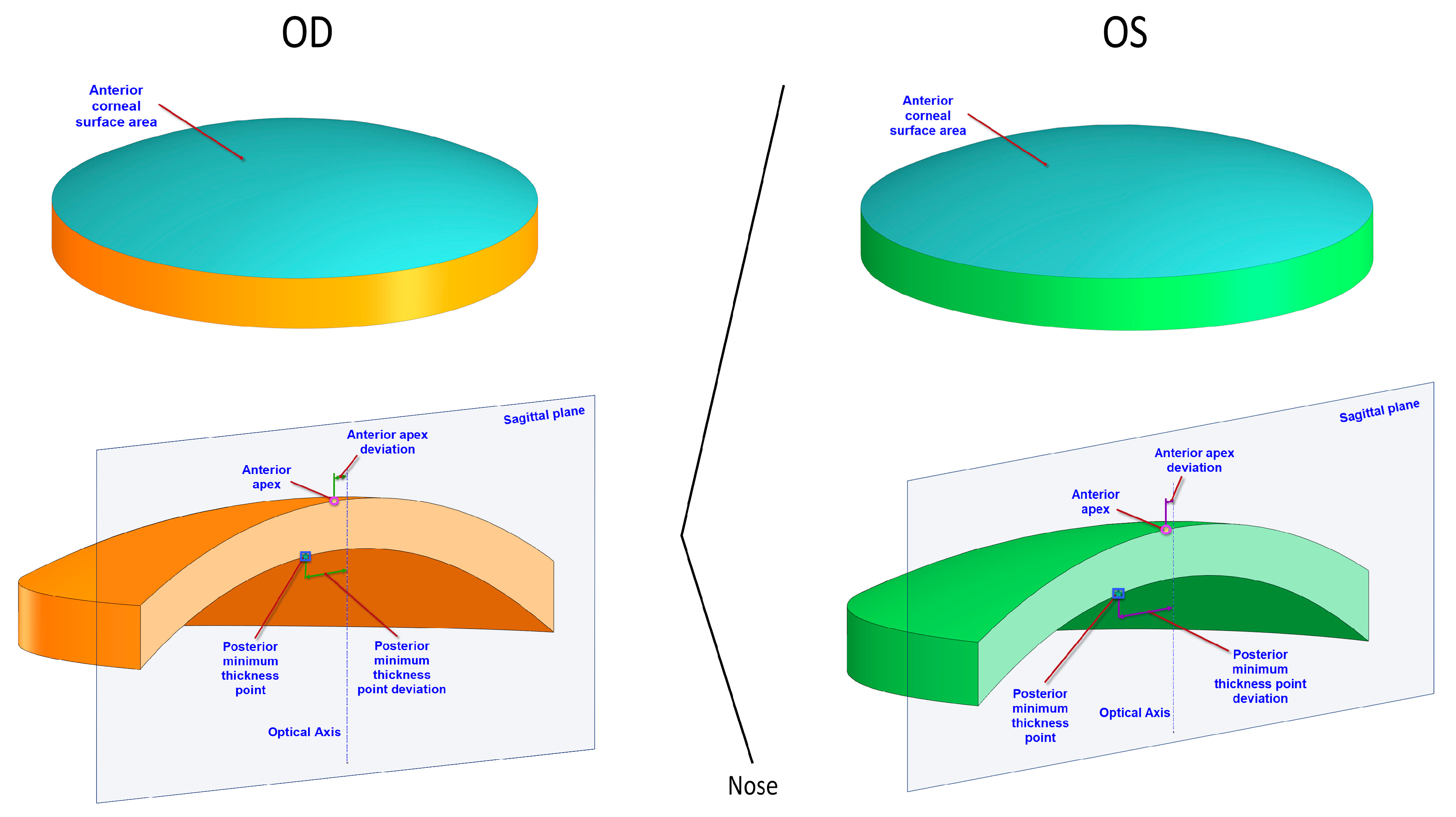
Anterior/posterior apex deviation (mm)Dapexant/DapexpostDistance from the optical axis to the apex of the anterior/posterior corneal surfaces
Anterior/posterior minimum thickness point deviation (mm)Dmctant/DmctpostDistance in the XY plane from the optical axis to the minimum thickness points of the anterior/posterior corneal surfaces
Table 2. Corneal shape parameters analyzed in axial symmetry of the corneal vertex pattern.
Shape ParametersAcronymDescription
Horizontal/vertical apical radius (mm)RX/RYRadius of curvature at apex with respect to x and y axes
Horizontal/vertical asphericityQX/QYAverage variation of instantaneous curvature at each point P along corneal meridian with respect to x and y axes
Angular coordinates of rotational displacement (°)α/β/γRotation in angular coordinates (α, β, γ) of x, y, and z axes with respect to the vertex (V) of a normal cornea (projection in XOY plane of a normal ellipsoid) toward the vertex (V0) of a perfect cornea (projection in XOY plane of a perfect ellipsoid)
Cartesian coordinates of translational displacement (mm)X0/Y0/Z0Distance in Cartesian coordinates (x, y, z) of the vertex (V) of a normal cornea (projection in XOY plane of a normal ellipsoid) toward the vertex (V0) of a perfect cornea (projection in XOY plane of a perfect ellipsoid)
Parameters of the ellipsoid (mm)a/b/cMain parameters of the canonical representation of ellipsoid of major adjustment
Table 3. Protocol of differences in the Cartesian elevation coordinates between pairs of points in direct symmetry and enantiomorphism.
Equal OctantsMirror Octants
ZA′ZA″ZA′ZE″
ZB′ZB″ZB′ZD″
ZC′ZC″ZC′ZC″
ZD′ZD″ZD′ZB″
ZE′ZE″ZE′ZA″
ZF′ZF″ZF′ZH″
ZG′Z G″ZG′Z G″
ZH′ZH″ZH′ZF″
Table 4. Summary of visual, refractive, and corneal topographic data in the right and left eyes of the sample evaluated. SD, standard deviation; SE, spherical equivalent; CDVA, corrected distance visual acuity; HOA, high-order aberration; RMS, root mean square; SA, spherical aberration; MCT, minimal corneal thickness; CCT, central corneal thickness.
MeasurementRight Eye (OD)Left Eye (OS)p-Value
Mean (SD)
Median (Range)
Mean (SD)
Median (Range)
Sphere (D)−0.03 (3.52)
0.25 (−10.00 to 8.50)
−0.20 (3.78)
0.00 (−12.00 to 8.00)
0.159
Cylinder (D)−0.60 (0.54)
−0.50 (−2.00 to 0.00)
−0.76 (1.07)
−0.50 (−5.75 to 0.00)
0.316
SE (D)−0.33 (3.46)
0.00 (−10.00 to 8.12)
−0.58 (3.72)
0.00 (−12.00 to 7.75)
0.126
Decimal CDVA1.00 (0.09)
1.00 (0.60 to 1.20)
1.00 (0.10)
1.00 (0.60 to 1.20)
0.892
Q4.5−0.11 (0.26)
−0.07 (−0.65 to 0.31)
−0.16 (0.24)
−0.18 (−0.65 to 0.19)
0.169
Q8−0.27 (0.21)
−0.29 (−0.78 to 0.10)
−0.27 (0.18)
−0.26 (−0.65 to 0.05)
0.990
HOA RMS (μm)
6 mm pupil
0.43 (0.12)
0.42 (0.25 to 0.76)
0.41 (0.11)
0.39 (0.4 to 0.70)
0.182
Coma RMS (μm)
6 mm pupil
0.29 (0.11)
0.30 (0.08 to 0.49)
0.27 (0.11)
0.27 (0.02 to 0.54)
0.102
SA (μm)
6 mm pupil
0.22 (0.05)
0.22 (0.13 to 0.35)
0.22 (0.06)
0.23 (0.08 to 0.32)
0.737
MCT (μm)539.2 (31.5)
541.9 (479.6 to 610.9)
540.3 (29.0)
540.5 (485.4 to 609.0)
0.448
CCT (μm)542.8 (31.8)
544.0 (482.0 to 615.0)
543.9 (29.4)
546.0 (489.0 to 614.0)
0.458
CV (mm3)25.8 (1.6)
26.2 (23.2 to 29.1)
25.9 (1.5)
26.1 (23.3 to 28.9)
0.565
Table 5. Summary of corneal morphogeometric data in right and left eyes of the sample evaluated.
MeasurementRight Eye (OD)Left Eye (OS)p-Value
Mean (SD)
Median (Range)
Mean (SD)
Median (Range)
Aant (mm2)43.09 (0.12)
43.08 (42.84 to 43.34)
43.10 (0.12)
43.13 (42.83 to 43.32)
0.055
Apost (mm2)44.27 (0.26)
44.29 (43.53 to 44.72)
44.28 (0.27)
44.28 (43.52 to 44.75)
0.572
Atot (mm2)104.04 (1.24)
104.07 (100.72 to 106.15)
104.08 (1.23)
104.14 (100.80 to 106.09)
0.580
Dapexant (mm)0.00 (0.00)
0.00 (0.00 to 0.00
0.00 (0.00)
0.00 (0.00 to 0.00
0.999
Dapexpost (mm)0.07 (0.02)
0.08 (0.03 to 0.13)
0.07 (0.02 to 0.65)
0.87 (0.22)
0.488
Dmctant (mm)0.89 (0.27)
0.89 (0.45 to 1.66)
0.87 (0.22)
0.88 (0.48 to 1.31)
0.659
Dmctpost (mm)0.81 (0.23)
0.84 (0.40 to 1.53)
0.79 (0.22)
0.77 (0.40 to 1.24)
0.606
Table 6. Summary of axial symmetry data at the vertex of the anterior corneal surface in the right and left eyes of the sample evaluated.
MeasurementRight Eye (OD)Left Eye (OS)p-Value
Mean (SD)
Median (Range)
Mean (SD)
Median (Range)
Rx (mm)7.62 (0.21)
7.58 (7.28 to 8.09)
7.61 (0.23)
7.55 (7.10 to 8.07)
0.549
Ry (mm)7.79 (0.19)
7.79 (7.52 to 8.24)
7.79 (0.19)
7.76 (7.49 to 8.19)
0.851
Qx−0.27 (0.11)
−0.27 (−0.51 to −0.05)
−0.27 (0.12)
−0.24 (−0.56 to −0.02)
0.981
Qy−0.25 (0.11)
−0.26 (−0.51 to −0.02)
−0.25 (0.12)
−0.23 (−0.49 to 0.00)
0.999
Alpha (°)−4.17 (28.62)
1.24 (−161.10 to 13.31)
−3.87 (25.53)
−0.39 (−143.08 to 13.49)
0.814
Beta (°)−0.05 (11.16)
1.10 (−52.67 to 27.55)
−2.05 (9.59)
−1.70 (−49.32 to 18.71)
0.012
Gamma (°)−43.08 (91.21)
−80.75 (−151.45 to 152.23)
−29.53 (10.50)
−80.55 (−176.10 to 173.43)
0.596
X0 (mm)0.20 (0.19)
0.14 (−0.13 to 0.88)
−0.18 (0.26)
−0.15 (−1.37 to 0.08)
<0.001
Y0 (mm)−0.003 (0.219)
−0.016 (−0.630 to 0.560)
0.036 (0.204)
−0.001 (−0.470 to 0.690)
<0.001
Z0 (mm)10.61 (1.70)
10.43 (8.12 to 15.25)
10.65 (1.86)
10.00 (8.19 to 15.99)
0.325
a (mm)8.98 (0.68)
9.00 (8.00 to 10.64)
8.98 (0.72)
8.80 (8.16 to 10.69)
0.994
b (mm)9.07 (0.68)
9.08 (8.17 to 10.84)
9.08 (0.77)
8.86 (8.22 to 11.46)
0.345
c (mm)10.63 (1.69)
10.43 (8.27 to 15.26)
10.67 (1.87)
10.01 (8.25 to 16.11)
0.845
Table 7. Summary of axial symmetry data at the vertex of the posterior corneal surface in the right and left eyes of the sample evaluated.
MeasurementRight Eye (OD)Left Eye (OS)p-Value
Mean (SD)
Median (Range)
Mean (SD)
Median (Range)
Rx (mm)6.21 (0.29)
6.25 (5.74 to 6.90)
6.22 (0.30)
6.27 (5.75 to 6.94)
0.466
Ry (mm)6.49 (0.29)
6.49 (6.00 to 7.06)
6.50 (0.27)
6.48 (6.00 to 7.13)
0.535
Qx−0.35 (0.21)
−0.33 (−0.99 to −0.08)
−0.34 (0.19)
−0.30 (−0.79 to−0.07)
0.606
Qy−0.32 (0.22)
−0.30 (−0.98 to −0.05)
−0.31 (0.19)
−0.28 (−0.75 to −0.04)
0.685
Alpha (°)6.15 (30.07)
−1.59 (−14.15 to 132.15)
4.70 (23.66)
−3.46 (−9.19 to 86.79)
0.562
Beta (°)−8.80 (19.68)
−3.87 (−73.89 to 7.58)
−6.30 (15.42)
−5.24 (−59.11 to 40.24)
0.506
Gamma (°)−22.62 (87.81)
−75.31 (−98.32 to 120.09)
−78.51 (45.54)
−90.51 (−108.98 to 86.76)
0.004
X0 (mm)1.49 (7.81)
0.06 (−0.62 to 44.91)
−0.23 (0.54)
−0.09 (−2.37 to 0.26)
0.229
Y0 (mm)1.09 (4.64)
0.17 (−0.10 to 26.81)
0.31 (0.42)
0.19 (−0.16 to 2.14)
0.335
Z0 (mm)22.39 (67.41)
9.97 (6.59 to 397.35)
10.99 (4.28)
9.34 (6.63 to 26.71)
0.331
a (mm)9.08 (7.14)
7.63 (6.04 to 48.19)
7.95 (1.42)
7.57 (6.10 to 12.24)
0.342
b (mm)9.28 (7.35)
7.73 (6.16 to 49.58)
8.13 (1.52)
7.71 (6.21 to 13.32)
0.345
c (mm)22.00 (67.99)
9.48 (6.32 to 400.21)
10.51 (4.29)
8.83 (6.34 to 26.39)
0.330
Table 8. Summary of angular-spatial symmetry elevation data of anterior and posterior corneal surfaces in the right and left eyes of the sample evaluated for a radius of 1, 2, 3, and 4 mm.
Right Eye (OD)Left Eye (OS)p-Value
MeasurementMean (SD)
Median (Range)
Most Common Position
Mean (SD)
Median (Range)
Most Common Position
Radius 1 mm
Anterior Zmax (mm)
0.07 (0.02)
0.07 (0.06 to 0.13)
Octants 7 (27.3%) and 3 (18.2%)
0.07 (0.01)
0.07 (0.06 to 0.13)
Octants 7 (33.3%) and 6 (18.2%)
0.984
Posterior Zmax (mm)0.63 (0.03)
0.64 (0.57 to 0.71)
Octants 2 (60.6%) and 1 (27.3%)
0.63 (0.03)
0.64 (0.58 to 0.70)
Octants 3 (69.7%) and 4 (21.2%)
0.247
Radius 2 mm
Anterior Zmax (mm)
0.27 (0.03)
0.27 (0.25 to 0.39)
Octants 3 (24.2%) and 7 (21.2%)
0.27 (0.03)
0.27 (0.25 to 0.38)
Octants 7 (30.3%) and 3 (15.2%)
0.950
Posterior Zmax (mm)0.88 (0.04)
0.89 (0.81 to 0.97)
Octants 2 (72.7%) and 3 (24.2%)
0.89 (0.04)
0.90 (0.81 to 0.97)
Octants 3 (84.8%) and 2 (9.1%)
0.171
Radius 3 mm
Anterior Zmax (mm)
0.62 (0.05)
0.61 (0.57 to 0.79)
Octants 3 (36.4%) and 7 (18.2%)
0.62 (0.04)
0.62 (0.57 to 0.78)
Octants 2 (24.2%) and 7 (18.2%)
0.900
Posterior Zmax (mm)1.31 (0.05)
1.32 (1.18 to 1.42)
Octants 2 (57.6%) and 3 (27.3%)
1.32 (0.05)
1.33 (1.18 to 1.40)
Octants 3 (72.7%) and 2 (15.2%)
0.560
Radius 4 mm
Anterior Zmax (mm)
1.05 (0.27)
1.12 (0.00 to 1.18)
Octants 3 (27.3%) and 2 (21.2%)
1.05 (0.27)
1.12 (0.00 to 1.18)
Octants 2 (24.2%) and 8 (24.2%)
0.936
Posterior Zmax (mm)1.93 (0.07)
1.94 (1.71 to 2.05)
Octants 7 (30.3%) and 3 (24.2%)
1.93 (0.07)
1.94 (1.73 to 2.05)
Octants 3 (36.4%) and 6 (27.3%)
0.745
Table 9. Summary of direct symmetry (equal octant) elevation data of anterior and posterior corneal surfaces between right (OD) and left (OS) eyes of the sample evaluated for a radius of 1, 2, 3, and 4 mm.
Radius 1 mmRadius 2 mmRadius 3 mmRadius 4 mm
ZX′ (OD) –
ZX″ (OS)
(Equal Octants)
Mean (SD)
Median (Range)
Mean (SD)
Median (Range)
Mean (SD)
Median (Range)
Mean (SD)
Median (Range)
p-Value (1 mm vs. 4 mm)
Anterior Corneal Surface
A′–A″ (µm)−0.09 (10.56)
−0.25 (−29.70 to 30.83)
−1.16 (21.56)
−1.39 (−63.46 to 63.42)
−5.48 (35.12)
-4.39 (-111.02 to 99.96)
−16.90 (384.25)
−10.15 (−1128.54 to 1061.36)
0.80
B′–B
(µm)
−0.07 (10.29)
−0.05 (−30.10 to 29.59)
−0.33 (20.53)
−0.02 (−63.00 to 58.30)
−0.58 (31.59)
0.33 (−95.62 to 91.05)
−2.92 (386.91)
2.90 (−1110.24 to 1088.41)
0.97
C′–C″ (µm)0.09 (9.76)
0.17 (−28.74 to 28.38)
0.98 (18.94)
1.34 (−54.76 to 55.54)
4.75 (28.78)
4.73 (−75.78 to 86.28)
11.19 (387.67)
6.41 (−1109.13 to 1098.68)
0.87
D′–D″ (µm)0.17 (10.06)
0.07 (−27.72 to 30.11)
0.79 (20.04)
0.30 (−54.64 to 60.80)
3.83 (31.91)
3.25 (−83.97 to 97.74)
12.57 (384.88)
15.39 (−1108.79 to 1085.62)
0.86
E′–E
(µm)
−0.01 (10.53)
−0.01 (−29.09 to 30.68)
−0.27 (21.47)
−0.09 −58.18 to 62.89)
0.25 (34.58)
1.54 (−92.19 to 100.23)
1.41 (387.93)
5.13 (−1128.11 to 1092.12)
0.98
F′–F
(µm)
−0.22 (10.34)
−0.22 (−29.25 to 29.88)
−1.14 (20.42)
−1.22 (−58.06 to 57.71)
−3.08 (31.37)
−2.92 (−89.28 to 85.70)
−10.02 (394.50)
−4.20 (−1164.97 to 1094.93)
0.89
G′–G″ (µm)−0.01 (10.02)
−0.16 (−28.37 to 28.96)
−0.75 (19.56)
−0.93 (−57.28 to 56.69)
−3.68 (30.24)
−2.25 (−91.96 to 85.11)
−15.21 (388.90)
−14.95 (−1147.93 to 1072.35)
0.83
H′–H″ (µm)0.13 (22.37)
−0.13 (−62.49 to 65.21)
−0.58 (42.56)
−1.48 (−119.22 to 126.11)
−4.16 (65.42)
−5.10 (−189.76 to 193.95)
−20.20 (381.52)
−19.01 (−1128.63 to 1048.49)
0.77
Posterior Corneal Surface
A′–A
(µm)
6.47 (14.79)
7.17 (−34.30 to 34.07)
16.40 (21.20)
17.39 (−37.99 to 54.74)
24.59 (28.43)
27.42 (−46.15 to 79.81)
−0.80 (50.65)
2.81 (−153.69 to 97.13)
0.43
B′–B
(µm)
−1.96 (11.86)
−3.13 (−36.25 to 18.43)
−1.81 (13.51)
−2.61 (−37.95 to 26.85)
−0.78 (16.93)
−0.79 (−46.78 to 35.16)
−5.75 (35.00)
−3.18 (−97.58 to 94.60)
0.54
C′–C
(µm)
−9.43 (13.38)
−8.70 (−48.50 to 12.81)
−16.81 (20.07)
−17.29 (−68.24 to 30.00)
−21.44 (30.21)
−27.50 (−86.19 to 40.59)
0.40 (46.52)
−2.52 (−90.91 to 103.92)
0.22
D′–D
(µm)
−16.97 (16.73)
−18.04 (−60.09 to 18.51)
−30.09 (27.06)
−33.49 (−92.33 to 41.95)
−43.19 (39.46)
−49.00 (−130.73 to 62.94)
−45.62 (58.76)
−54.94 (−185.60 to 81.02)
<0.01
E′–E
(µm)
−12.02 (14.19)
−11.53 (−53.86 to 16.79)
−23.78 (21.59)
−27.86 (−79.60 to 30.69)
−37.76 (31.63)
−44.22 (−113.25 to 43.88)
−47.13 (46.55)
−52.98 (−148.28 to 74.72)
<0.01
F′–F
(µm)
−4.03 (12.16)
−3.13 (−39.68 to 12.03)
−5.85 (13.13)
−4.84 (−49.54 to 12.84)
−7.74 (16.81)
−4.66 (−68.22 to 16.58)
−9.24 (24.93)
−3.74 (−88.05 to 33.27)
0.20
G′–G
(µm)
5.45 (14.90)
5.75 (−32.47 to 30.66)
14.99 (21.18)
15.17 (−33.76 to 49.16)
26.09 (31.88)
26.32 (−35.20 to 91.49)
34.39 (44.94)
36.42 (−58.31 to 135.05)
<0.01
H′–H″ (µm)11.15 (17.61)
10.94 (−29.37 to 43.27)
24.40 (27.58)
23.86 (−50.35 to 73.36)
39.14 (40.38)
41.86 (−63.25 to 115.43)
44.10 (56.82)
53.20 (−84.18 to 136.37)
<0.01
Table 10. Summary of enantiomorphism (mirror octants) elevation data of anterior and posterior corneal surfaces between right (OD) and left (OS) eyes of the sample evaluated for a radius of 1, 2, 3, and 4 mm.
Radius 1 mmRadius 2 mmRadius 3 mmRadius 4 mm
ZX′ (OD)–
ZX″ (OS)
(Mirror Octants)
Mean (SD)
Median (Range)
Mean (SD)
Median (Range)
Mean (SD)
Median (Range)
Mean (SD)
Median (Range)
p-Value
(1 mm vs 4 mm)
Anterior Corneal Surface
A′–E″ (µm)0.58 (10.32)
0.40
(−27.33 to 30.89)
1.77 (20.54)
0.74 (−53.01 to 62.89)
3.14 (32.21)
0.87 (−84.19 to 99.34)
5.72 (381.94)
8.53 (−1108.79 to 1061.36)
0.94
B′–D″ (µm)0.50 (10.02)
0.27 (−28.03 to 29.46)
2.58 (19.31)
2.03 (−52.23 to 58.00)
7.84 (29.07)
8.44 (−73.10 to 91.29)
13.75 (386.94)
15.69 (−1109.13 to 1088.41)
0.84
D′–B″ (µm)−0.33 (10.21)
−0.29 (−30.15 to 30.03)
−2.42 (21.03)
−2.21 (−65.08 to 61.32)
−5.73 (35.17)
−5.30 (−110.80 to 98.36)
10.23 (380.81)
−8.30 (−1128.5 to 1085.6)
0.88
E′–A″ (µm)−1.62 (17.15)
0.12 (−62.01 to 31.01)
−2.29 (33.19)
−0.04 (−116.23 to 64.37)
−2.45 (52.18)
−0.19 (−180.32 to 105.19)
2.16 (386.87)
−0.66 (−1128.63 to 1092.12)
0.96
F′–H″ (µm)0.30 (10.19)
0.14 (−27.81 to 30.23)
0.48 (20.22)
−0.39 (−54.80 to 59.90)
0.02 (31.73)
−2.51 (−83.85 to 94.17)
−5.74 (391.77)
−6.42 (−1147.93 to 1094.93)
0.93
H′–F″ (µm)1.74 (17.62)
−0.26 (−29.22 to 65.39)
1.44 (33.94)
−2.50 (−61.17 to 124.64)
−1.46 (52.06)
−5.17 (−101.63 to 188.99)
−20.95 (382.57)
−17.90 (−1128.11 to 1048.49)
0.75
Posterior Corneal Surface
A′–E″ (µm)1.30 (13.15)
3.53 (−35.48 to 30.05)
9.27 (16.09)
10.75 (−39.66 to 47.90)
19.23 (23.57)
21.42 (−60.39 to 61.40)
3.03 (43.54)
1.46 (−122.71 to 88.32)
0.80
B′–D″ (µm)−2.07 (12.42)
−0.41 (−39.52 to 19.39)
2.50 (16.74)
2.37 (−46.78 to 40.59)
11.73 (23.89)
8.10 (−54.86 to 61.41)
19.70 (35.15)
23.77 (−83.97 to 75.25)
<0.01
D′–B″ (µm)−1.18 (12.10)
−9.28 (−47.86 to 9.28)
−2.29 (14.93)
−19.59 (−59.99 to 2.77)
−3.78 (21.35)
−38.66 (−85.13 to 3.66)
−4.94 (32.51)
−51.41 (−134.6 to 35.74)
<0.01
E′–A″ (µm)−3.15 (11.82)
−1.86 (−38.47 to 16.47)
−2.04 (13.41)
1.18 (−36.67 to 21.08)
1.98 (18.06)
4.25 (−47.29 to 45.80)
11.07 (30.47)
11.78 (−69.37 to 95.99)
<0.01
F′–H″ (µm)1.44 (13.00)
1.84 (−35.00 to 18.67)
10.58 (16.16)
8.61 (−25.13 to 45.23)
22.22 (22.23)
22.50 (−29.92 to 77.71)
29.84 (37.33)
34.44 (−56.98 to 115.93)
<0.01
H′–F″ (µm)2.29 (13.48)
2.30 (−35.86 to 24.85)
2.67 (15.91)
2.29 (−44.93 to 36.23)
−0.60 (21.62)
1.71 (−69.32 to 44.15)
−14.09 (34.85)
−7.11 (−126.26 to 43.76)
<0.01

