Two-Degree-Of-Freedom Dynamic Model-Based Terminal Sliding Mode Control with Observer for Dual-Driving Feed Stage


1
School of Engineering, Huazhong Agricultural University, Wuhan 430070, China
2
School of Mechanical and Electronic Engineering, Wuhan University of Technology, Wuhan 430070, China
3
School of Mechanical Science and Engineering, Huazhong University of Science and Technology, Wuhan 430070, China
4
Department of Mechanical Engineering, School of Engineering, University of Birmingham, Birmingham B15 2TT, UK
*
Author to whom correspondence should be addressed.
Symmetry 2018, 10(10), 488; https://doi.org/10.3390/sym10100488
Submission received: 24 August 2018
/
Revised: 2 October 2018
/
Accepted: 9 October 2018
/
Published: 12 October 2018
(This article belongs to the Special Issue Emerging Data Hiding Systems in Image Communications)
Abstract
:The position synchronous control of multi-axis gantry-type feed stage is crucial in precision machine tools. Industrial position control which aims to widen the bandwidth and improve disturbance rejection of single axis is not enough to achieve precise synchronization in a dual-driving feed stage. The characteristics diversity, transmission-mechanism deformation, and mechanical coupling effect between dual axes will degrade the control accuracy. Hence, the novel two-degree-of-freedom (2-DOF) dynamic model-based terminal sliding mode control (TSMC) with disturbance and state observer is proposed in this paper for the synchronous control of a 2-DOF dual-driving feed stage. The 2-DOF dynamic model, based on Lagrange equation, is established along with the parameters identification method. The predictive natural frequencies and vibration modes frequencies by the proposed dynamic model are compared by a modal experiment. Then, the 2-DOF dynamic model-based TSMC is provided to satisfy the tracking and synchronization control. In order to reduce the chattering and to increase the robustness against the mechanical coupling, the disturbance and state observer is designed. Moreover, Lyapunov stability criterion is used to analyze the stability of the proposed control scheme. Finally, an industrial application of 2-DOF dual-driving feed stage is utilized to validate the effectiveness of the proposed control scheme. The proposed 2-DOF dynamic model-based TSMC with observer has been effectively demonstrated to improve synchronous performance and tracking accuracy.
1. Introduction
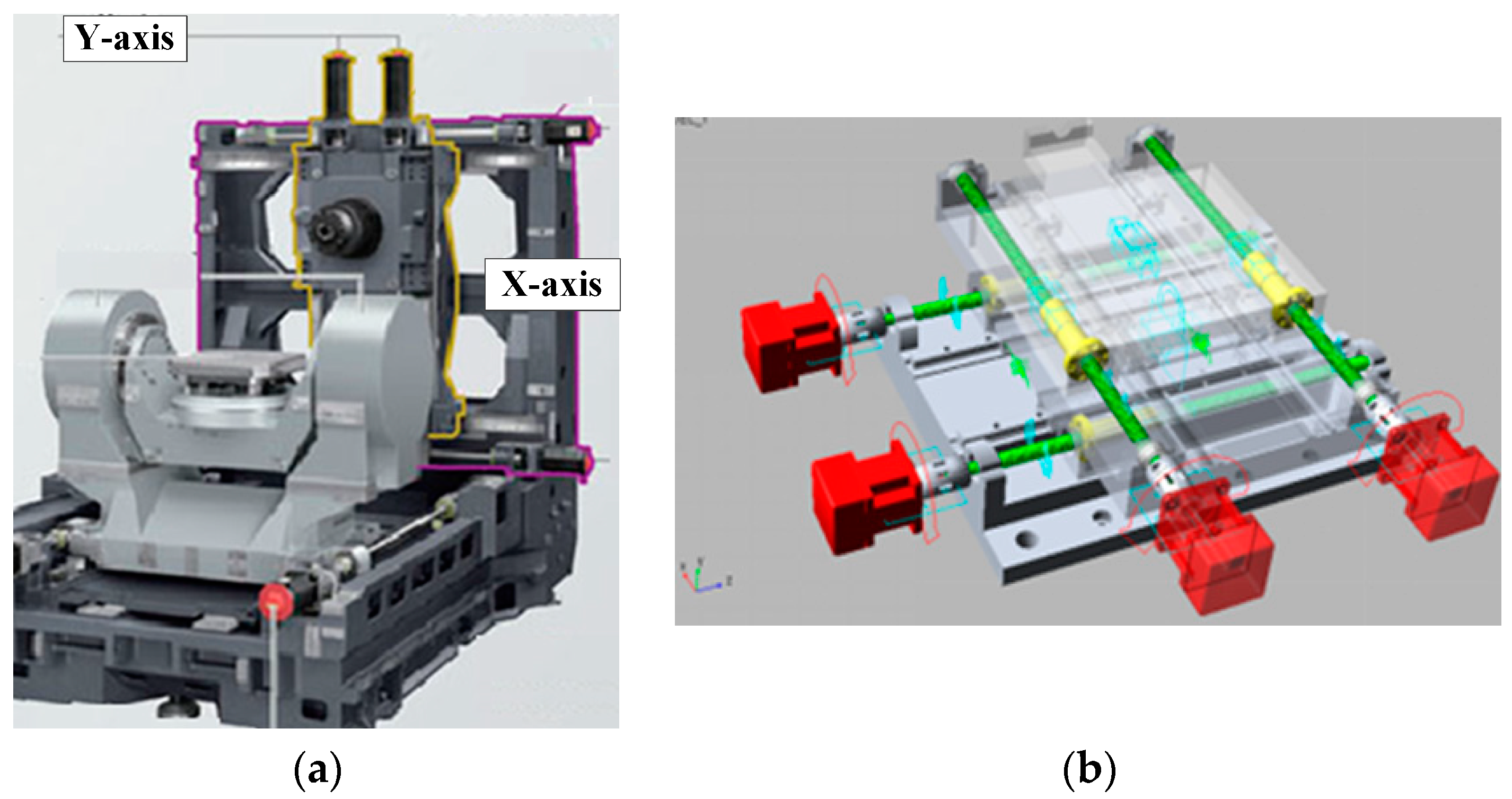
With the increasing demand for higher precision and greater productivity, modern manufacturing techniques have been in rapid development. Many advanced manufacturing machines such as gantry machine, computer numerical control (CNC) engraving machine, coordinate measurement machine and robotic arms are required to have multi-axis synchronous or coordinated motion [1]. In the configuration of the two-degree-of-freedom (2-DOF) dual-driving feed stage, dual ball-screws and motors are mounted parallel to each other in each feed direction of a planar motion. Since the joint force is provided by double motors and screws, the dual-driving structure can significantly increase the feed rigidity and overall thrust. An innovative industrial implication of 2-DOF dual-driving feed stage is proposed by Mori Seiki [2]. The stage which is moved by dual motors in its systematic configuration can generate higher acceleration and precision, as shown in Figure 1.
However, the dual-driving synchronous feed mechanism has also brought some additional concerns. Although the dual axes have the same mechanical structure, the synchronous error is unavoidable due to the unbalanced forces, characteristics diversities, and mechanical coupling of dual axes [3,4]. In addition, the damage may even occur when significant desynchronization takes place. The normal industrial motion control is usually performed by widening the bandwidth and improving the resistance capacity against disturbance independently on the single axis, which cannot guarantee the synchronization performance of dual axes. To overcome the drawback, the appropriate control scheme along with the dynamic characteristics analysis is required to satisfy the tracking and synchronization accuracy as the dual-driving stage traces a complex trajectory [5].
Many researches have explored the errors modelling and compensation methods of machine tools. Some scholars provide the methodology for the estimation of the geometrical errors of the multi-axis machine, based on the Denavit and Hartenberg’s formulation. In this method, the elemental error in each joint has been defined for a multitasking machine and calculated by homogenous matrix [6,7]. These error modelling methods are often used in the serial multi-axis machine tool, and can be helpful to the research for error compensation in the dual-driving feed system.
As for the synchronous control, the most recent tandem approach is mechanical rigid coupling. Both axes are joint feeds based on the mechanical line-shaft or connection rods [8]. However, the performance of mechanical rigid synchronization is heavily dependent on the machining and assembly accuracy and has a poor flexibility when the structure or application changed for its complex structure.
With the development of electrical technology, the master-slave control which follows the tandem structure becomes a potential solution. In master-slave control, the position or velocity signal of the master motor is used as reference command to the slave. For its convenient application, the master-slave control has been adopted widely in industry, such as FANUC Ltd. and speed/torque coupling control in SIEMENS [9,10]. In addition, the electronic virtual main shaft control has been developed to eliminate the unbalanced problem based on the master-slave theory [11]. Nevertheless, the tandem structure generates an unavoidable delay between the dual axes and the load disturbance imposed on the slave axis cannot be fed back to the master, which leads to a poor dynamic synchronization performance.
The cross-coupled control was initially proposed for contour processes and has been extended by many scholars. In cross-coupled control, each axis has its own reference command and feedback. This arrangement allows reflecting any load disturbances presented in both axes by using the additional signal as an additional tracking signal via weighted gains [12,13]. However, cross-coupled control is achieved by a synchronous controller. The controller will calculate the position error of dual axis in the closed-loop, which fundamentally makes the dual axis follow and move against each other in high frequency, which is defined by the controller and sampling rate. The following process of dual-driving axes inevitably generates an oscillation of the dual-driving system [14,15].
Traditional algorithms such as P, PI, and PID or more robust ones such as adaptive and H-infinity controller can be used in combination with the master-slave and cross-coupled control structure [16,17]. The sliding mode control (SMC) is particularly suited to dual-driving systems for its lesser sensitivity to the external disturbances and modeling accuracy. The fuzzy neural network SMC system is proposed to achieve both tracking accuracy and synchronous motion control for dual linear motor motion control system. The fuzzy logic control is presented in some researches to eliminate the unknown dynamics, and the adaptive fuzzy SMC is also proposed to achieve a better performance [18,19]. Compared to normal SMC, the terminal sliding mode control (TSMC) guarantees state convergence to sliding surface in finite time. Therefore, the TSMC is suitable for high synchronization performance dual-driving applications [20]. In our previous work, the cross-coupled fuzzy SMC scheme was designed, while the flexible mechanical driver body model was not taken into consideration [21].
Many researches have been provided to analyze the forces and disturbances in processing [22,23]. Some scholars designed the data acquisition system to simultaneously record the cutting forces and cutting tool positions [24]. However, to control the dual-driving system, the transmission system is usually developed by the simplified screw transmission ratio, and the mechanical coupling is ignored [6,9,10,11,12]. Some scholars studied the dynamic modelling in order to deal with the mechanical coupling disturbance that exists in various dual-driving stages. However, the model usually only takes into account the mass and inertia of the components, and ignores the flexible deformation and vibration of the transmission-mechanism [13,14]. Considering the system identification test to obtain the dynamic characteristics of the dual-driving mechanical structure, some scholars develop the lumped parameter model for ball screw system, and design the acceleration feedforward controller based on the transfer function of the overall drive system. The screw system is taken as a rigid body, and the coupling effect due to mechanical linking can be identified as a first-order inertial transfer function [25,26], which degrades the accuracy of the dynamic model.
Hence, there are two main problems restricting the development of the dual-driving feed system. Firstly, the synchronization precision is affected by the diversities of system characteristics, transmission features, and vibration. Secondly, the mechanical-coupling can give rise to the desynchronization or even mechanism damage in industry application. Especially in the sudden change of acceleration, the mismatch disturbances between the unbalanced driving force and dynamic characteristics of dual axes will cause a fluctuation of synchronous error. Hence, the characteristics diversity, flexible deformation, and mechanical coupling should be taken into account for dynamic modeling. Based on it, the strategy of the synchronous control should be robust against the coupling between two drives and penalize synchronous errors that are generated due to disturbances, as well as parameter diversities, when performing the TSMC and observer design.
This paper is organized as follows: Section 2 presents the modelling and analysis of the 2-DOF dual-driving feed stage. The dynamics model is verified by the modal test. Section 3 proposes the dynamic model-based TSMC, and the disturbance and state observer is developed to deal with the mechanical coupling disturbance. Then, the Lyapunov stability analysis of the proposed synchronous control scheme is provided to guarantee closed-loop tracking stability. In Section 4, the tracking and synchronization performance of the proposed 2-DOF dynamic model-based TSMC with observer control scheme is compared with the other two synchronous control schemes by experiment. The experimental results show the effectiveness of the proposed control scheme. Conclusions are drawn in Section 5.
2. Modelling and Analysis of 2-DOF Dual-Driving Feed Stage
2.1. 2-DOF Dual-Driving Dynamic Model
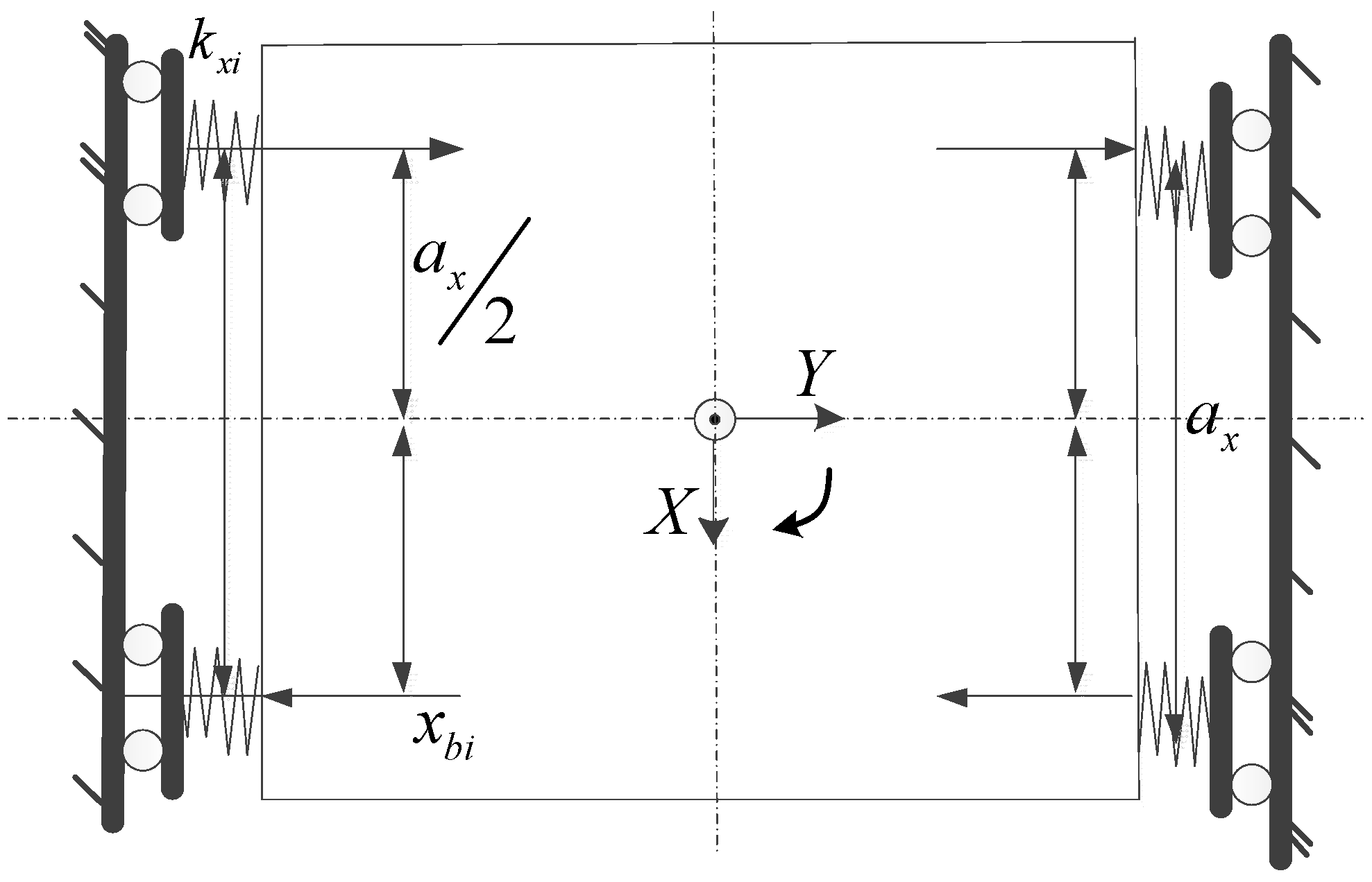
The 2-DOF dual-driving feed stage and coordinate are shown in Figure 2. It consists of a gantry stage which is moved by twin parallel actuators on the X-axis and also twin actuators on the Y-axis. To provide high synchronization and tracking accuracy, Permanent Magnet Synchronous Motors (PMSM) and ball screws are equipped on each feed direction. The feed process is accomplished by two-layer dual-driving moving. The lower layer dual-driving motors which take charge of the X-axis motion are mounted on the base. The upper layer in Y-axis holding the workpiece is mounted on the moving stage, which is also driven by two parallel motors and screws. The workpiece is usually installed on the slider according to customers’ requirements. In practice, the dual displacements in each degree of freedom are different because of the unbalanced forces, characteristics diversities, and mechanical coupling of the dual axes. The displacements difference is defined as a synchronous error which should be eliminated. The central point O of the stage is constrained to move along the center line of two DOF, the displacements are denoted by and . Furthermore, the sliding stages may also rotate due to the desynchronization between and , and and . The rotational angles are denoted by and , respectively.
To proceed with the dynamic model of the 2-DOF dual-driving stage, two sets of coordinates can be used to describe the geometrical relationship of the gantry stage. One set is given by coordinates (), which are the measured positions of each actuators in two dimension. The second set is given by the equivalent coordinates (), which express the relationship between linear and rotational angle displacements of the stage.
and denote the mass of the lower layer and the upper layer stage, respectively. The moment of inertia of the lower layer and the upper layer stage are expressed as
The translational and rotational kinetic energy of the gantry stage and slider are expressed as
Equation (3) can be rewritten as
where and is the simplified inertia matrix
Moreover, the total kinetic energy can be computed as
and are the lateral stiffness’ of the slider on the X-axis and Y-axis. According to the configuration in Figure 1, and are the small angular displacements.
Two sets of geometric relationships on the X-axis and Y-axis can be used to specify the displacements of slide blocks. Then, the displacements of each axis can be expressed as
where and are the displacements of the nuts of each axis, and and are the displacements of the gantry stage and slider in X and Y directions. From (7) we can see that the synchronous errors between the displacements and are affected by the yaw errors , which means that the research of yaw error is necessary to improve the feed accuracy. The yaw errors are reflected in the synchronous errors.
As can be seen in Figure 3, the diagram of lateral deformation of slide blocks in the lower layer along the direction of the Y-axis is expressed. The lateral deformation of slide blocks of the upper layer along the direction of the X-axis can be derived by approximate approach. The relationship between the lateral deformations of the slide blocks and torsion angles is given by
According to the Lagrange method, the system dynamics can be defined as
where
Finally, the dynamic model of 2-DOF dual-driving feed stage can be rewritten as
where and are the simplified inertia (5) and stiffness (13) matrices; is the force vector (14)
The stiffness matrix points out the mechanical coupling between the dual-driving axes and in the multi-degree of freedom, which is affected by equivalent stiffness , , , and different location positions of nuts and on each axis. The simplified inertia and damping matrices show the non-uniform load and friction distribution. F is the force vector which is affected by the displacements and in X-axis and Y-axis. In each feed direction, the displacements of the dual axis should be equal, implying , , and . However, in practice, due to the different mechanical and servo characteristics of dual-axis, and the mechanical coupling effect, perfect 2-DOF dual-driving is hard to be achieved.
2.2. Comparison between Experimental and Model Simulated Results
In order to verify the 2-DOF dynamic model, experimental and model simulated results are compared in this section. The industry milling machine that has a 2-DOF dual-driving stage is used as experimental set-up. The modal analyzer is used to conduct the modal test. The pulse hammer is used to actuate the excitation force of frequency with finite width. The response of the stage is detected by the acceleration sensors which are arranged at four corners of the stage. The data filtering and A/D conversion are processed by the amplifier and frequency analyzer. The model test block diagram is shown in Figure 4. According to the sampling theorem, the sampling frequency is designed to be 1000 Hz, which can ensure the reliability of measured vibration data.
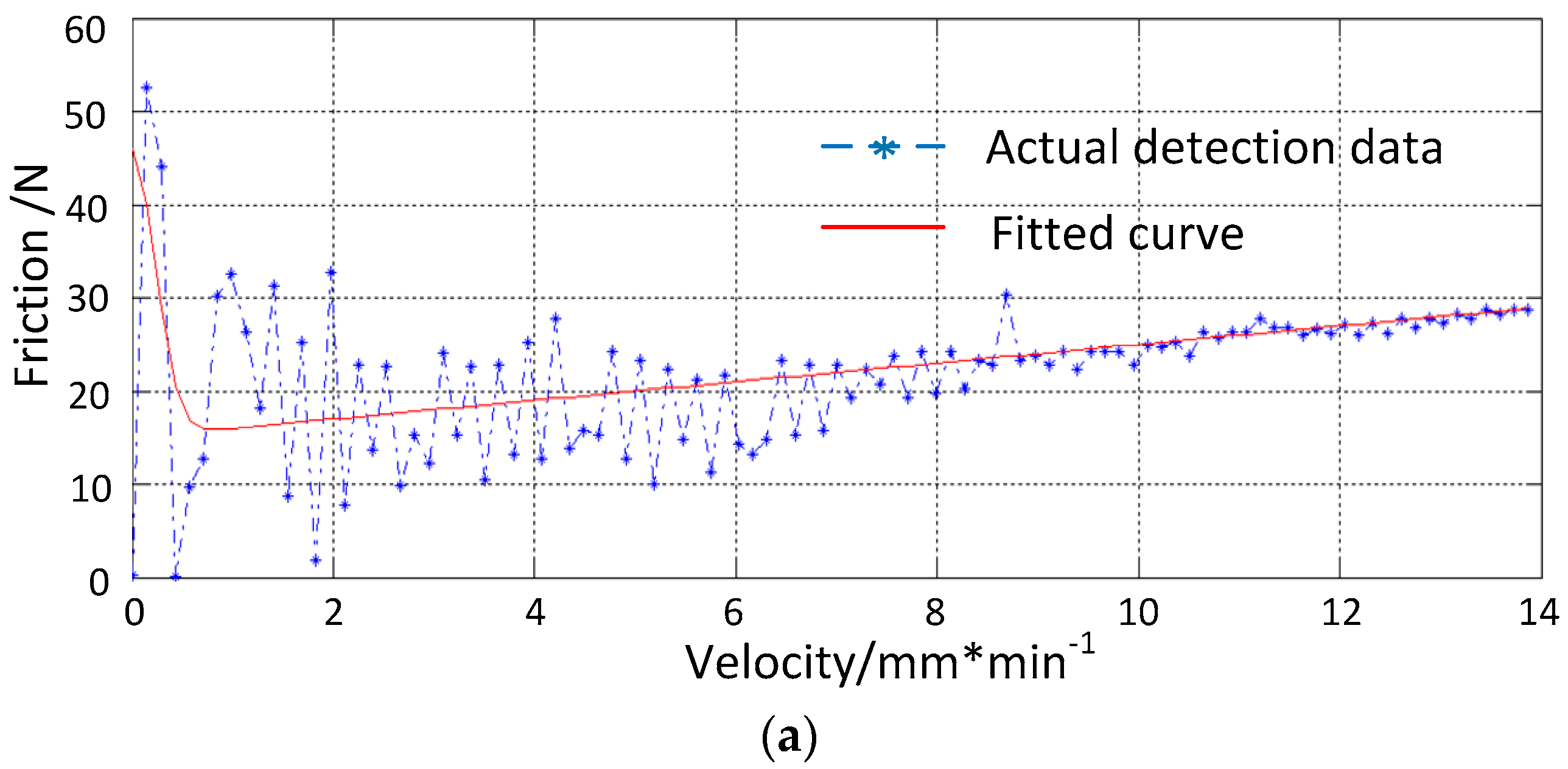
Different frictional characteristics will generate the unbalanced forces in double axes. So the frictions model should be built accurately. The non-linearity friction model is described according to the Stribeck model [27]
where is the Stribeck velocity, is Coulumb friction and is the maximum static friction. The friction can be identified by measuring the output torque when the stage is displaced at various constant velocities. The variation of velocity is 5 mm/s~14m/min. The measured data can be processed by nonlinear fitting function of MATLAB. The friction model of X-axis is expressed in Figure 5, and the parameters of the Stribeck model are shown in Table 1.
The detailed parameters identification method, such as the equivalent mass and stiffness, which can be found in Reference [28], is described by measuring the motor output torque when the stage is displaced at various constant velocities. The physical parameters of the 2-DOF dual-driving feed stage are listed in Table 2.
Solving the dynamic equation by substituting the physical parameters in (12)–(15), the eigenvalues and eigenvectors of the system can be obtained. The eigenvalues correspond to the natural frequencies of each order, and the eigenvector can be normalized to analyze the vibration mode.
In fact, the vibration energy of the high order mode only accounts for a small proportion of the total vibration energy in the mechanical system. Hence, due to the existence of high order modal damping, it is difficult to stimulate the high order resonance in the actual working condition. Moreover, the bandwidth of the servo system is about 200–500 Hz in practical engineering. Therefore, the first four order natural frequencies that will affect the feed performance are detected and analyzed. Through the modal test, the acceleration time domain signal that is detected by the acceleration sensor is shown in Figure 6a. The acceleration time domain signal fluctuates around zero in steady state, which is the amplitude of vibration in one test. In order to analyse the natural frequency of the stage, the acceleration time domain signal is processed by Fourier transformation. The frequency response can be obtained as shown in Figure 6b. As shown in Figure 6b, the natural frequencies from the first order to the fourth order of 2-DOF feed stage are: 33.82 Hz, 112.4 Hz, 356.3 Hz, and 407.1 Hz. The first two order natural frequencies have large amplitude, which means the observable resonance of stage will be produced when the working frequency is closed to 33.82 Hz and 112.4 Hz.
Then the simulated and experimental natural characteristics are compared to validate the dynamic model. The simulated natural frequencies and modes are obtained as shown in Table 3. The comparison of natural frequencies between the modal test and simulation are shown in Table 4. As can be seen in Table 4, the relative errors between model simulation and modal experiment are within 10.2 %. Due to the effect of damping, the simulated natural frequencies will be slightly higher than the actual test frequencies.
3. Two-Degree-Of-Freedom Dynamic Model-Based Sliding Mode Control
The 2-DOF dynamic model-based TSMC is proposed in this section. The diagram of the control scheme is shown in Figure 7.
3.1. Terminal Sliding Mode Control Design
In the practical scenario, the displacements of each axis , , , and are measurable. The state variables are defined as , ; and the measurement variables are , . Thus the dynamic model of the 2-DOF dual-driving gantry stage can be rearranged as
Considering the parameters variation and unknown dynamics of the gantry position stage, (17) can be rewritten as
where is the lumped uncertainty, , , , , and . In (18), the mechanical coupling is modeled as disturbances.
For the 2-DOF dual-driving feed system, in each feed direction, the control scheme can be separated in two components at the same time: The first one is to eliminate the tracking error according to a given position signal; and the second one is to preserve the synchronous position with the other motor. According to the hybrid question, in this paper, the individual SMC with an extra cross-coupled synchronous controller is proposed to handle with the dual-driving hybrid error simultaneously to eliminate the complementary synchronous error and achieve the quick and accurate tracking of the given position signal.
As for the single axis, the position tracking error can be described as follows
The second derivative of (21) can be found as
where and are the reference position command in X and Y directions, and are the actual displacements of ith axis in X and Y direction, and are the errors between actual displacements and reference positions of the ith axis in X and Y directions.
The synchronous errors between dual axes in X and Y directions can be expressed as
The control objective of the 2-DOF feed stage is to guarantee the tracking error and the synchronous error to be zero simultaneously. The individual SMC is adopted as a class of nonlinear control approach in the drive dynamics, to eliminate the tracking errors and . What is more, to eliminate the synchronous error, a synchronous controller should be designed to generate the relationship between the input and the actual synchronous error , caused by displacement and . Then the comprehensive error can be rewritten as
For its advantages of being completely insensitive to system parameter variations and modeling inaccuracies, SMC is particularly suited for a nonlinear system. A SMC is designed based on the dual-driving model, the control objective is to generate a robust sliding mode controller to force the actual motion position to track the given bounded desired reference trajectory, this can guarantee the comprehensive error converges asymptotically to zero.
Sliding surface is the first step to design a sliding mode controller, the terminal sliding variable is defined as
where is the sliding surface constant to be designed, which should be a positive constant like a transmission gain to determine the convergence speed of the dynamic error on the sliding surface. and are odd integers satisfying .
Taking the derivative of (25), we have
Considering the stability of the overall system using the proposed TSMC, defining the following Lyapunov function
Take the derivative of (27), one can obtain
Evaluating the derivative of the Lyaponov function along the dynamics of the system in (28), we have
The negative sufficient condition of (29) can be designed as
where .
Considering the 2-DOF dynamic model as shown in (17), the model-based TSMC control law can be designed as follows
Since is the bounded total force which satisfies , where . Considering the definition of sliding surface function, the estimation of error can be derived as
Then the Lyapunov function can be found as
Apparently, is negative semidefinite.
3.2. Disturbance Observer and State Observer Design
As can be seen from model (12)–(15), the disturbance is composed of disturbances and coupled force of 2-DOF dual-driving axes. In the conventional sliding mode control, the switching parameter is required to be larger than the bound of the disturbance . Therefore, if is estimated and compensated by a disturbance observer in the TSMC, a small switching parameter can be designed and can reduce the risk of chattering.
The following disturbance estimation error is defined, which penalizes deviation of errors from the sliding surface.
where and , because is required in the calculation of , can be induced.
Since the disturbance observer is postulated to penalize deviation of error dynamics from the sliding surface, therefore, the disturbance observer can be designed as
can be assumed because the dynamics of the disturbance observer are much higher than the actual disturbance with interested frequency components. The dynamics of the disturbance estimation error can be expressed as
Moreover, the dynamic expression of the state observer can be modeled by system model (17)
The estimation error of state variables is defined as
Replacing the state variables given in (18)–(20), the dynamics of the state observer are obtained
where .
The error dynamics of the observer (36) and (39) can be combined as
where , and .
The following Lyapunov function is chosen to derive stability of the observer
where is a positive definite matrix, and P1 and P2 are the parameters that need to be designed. The derivative of the Lyapunov function can be given as [29]
The parameters are designed to guarantee the convergence of the observers, which means the Lyapunov function of observer need to be a negative definite matrix. Hence, the parameters can be obtained by solving the linear matrix inequality (LMI)
For solving the LMI, (43) can be rewritten as
Therefore, the main idea behind the design of the proposed model-based TSMC scheme is that the control variables are errors calculated by the dynamic model instead of linear errors measured by the grating scale. Moreover, the disturbances due to the mechanical coupling of 2-DOF dual-driving feed stage can be compensated by the disturbance and state observer, while the effect associated with the acceleration and force of the stage is compensated by the TSMC control.
4. Experimental Validations
4.1. Experimental Set-Up
In order to verify the proposed dynamic model-based TSMC scheme, the comparison experiments are carried out on the industry milling machine tool in this section. The experimental set-up is sketched in Figure 8 and Figure 9, including 2-DOF dual-driving feed stage, control card, drive and control panel. In each motion direction, there are twin motors and screws arranged in parallel. Each motor is controlled by a servo driver in current mode. The feed velocity of each motor can be set from 5 mm/s to 250 mm/s. For the high precision implementation of the 2-DOF dual-driving feed stage, each motor is installed with a linear encoder as the position sensor, and the linear optical scales with a resolution of 0.1 μm.
The implementation diagram of the closed loop synchronous control system is shown in Figure 8. An embedded control card is used as the motion controller in the control system. The real-time control scheme is applied to the servo system by using “C” and MATLAB/SIMULINK language. All the programs, such as motion control, NC tasks, and PLC program, are developed in the PC under Windows environment and then can be called by the control card in the DSP for real-time implementation. The overall system is formed with EtherCAT Bus technique with the scan cycle of 0.1 ms. The PMSMs are driven in current control mode, and the current loop which exists inherently in the drive has been tuned properly. After the input command is set, the tracking and synchronization errors can be calculated by the position feedback of an absolute grating ruler at 10 KHZ sampling frequency. The proposed control algorithm which is called by motion control card can transfer the errors to proper voltage command. Finally, the motion and error compensation of PMSMs are executed by the desired voltage which is amplified by the servo drive.
The physical parameters of adopted PMSMs in the experiment are listed in Table 5. The parameters of each motor are identified and selected by manual.
The original TSMC system’s gain is set. This gain coefficient is designed according to all the roots of and is located in the open left half plane. The switching gain, can be designed and determines the robustness of the system under external disturbances and parameters perturbation. A large switching gain will directly affect the dynamic control performance, however, it will also lead to the chattering phenomenon of TSMC. Considering , and are designed to satisfy the speed when the system approaches the sliding surface. The comparison of control law and control force is shown in Figure 10 and Figure 11, and the comparison between estimated and actual disturbance is shown in Figure 12.
4.2. Experimental Results
To investigate the effectiveness of the proposed dynamic model-based control scheme with the change of speed and acceleration, Figure 13 shows the experimental reference periodical sinusoidal trajectory with the mm stroke. The velocity and acceleration of axes , , and are, respectively, 320 mm/s and 3200 mm/s2. In the configuration of the experiment system, the initial imbalance between the dual-drive axes at each feed direction is zero. The mechanical limit for the desynchronization between dual-axes in each feed direction is mm. The desynchronization limits of position and torque have been designed by program, and the system will come to a stop to avoid damage.
Figure 14, Figure 15 and Figure 16 displays the experimental results of the command tracking due to periodical sinusoidal trajectories of the cross-coupled PID control, cross-coupled normal TSMC, and the proposed dynamic model-based TSMC, respectively.
The tracking errors of the and axis of the cross-coupled PID control are shown in Figure 14a, and the tracking errors of the and axis of the cross-coupled PID control are shown in Figure 14b. The synchronous errors between the and axis of the cross-coupled PID control are shown in Figure 14c, and the synchronous errors between the and axis of the cross-coupled PID control are shown in Figure 14d. The tracking errors of the and axis of the cross-coupled normal TSMC are shown in Figure 15a, and the tracking errors of the and axis of the cross-coupled normal TSMC are shown in Figure 15b. The synchronous errors between the and axis of the cross-coupled normal TSMC are shown in Figure 15c, and the synchronous errors between the and axis of the cross-coupled normal TSMC are shown in Figure 15d. The tracking errors of the y1 and y2 axis of the proposed dynamic model-based TSMC with observer are shown in Figure 16a, and the tracking errors of the and axis of the proposed dynamic model-based TSMC with observer are shown in Figure 16b. The synchronous errors between the and axis of the proposed dynamic model-based TSMC with observer are shown in Figure 16c, and the synchronous errors between the and axis of the proposed dynamic model-based TSMC with observer are shown in Figure 16d.
From the quantitative analysis of the experimental results of the tracking and synchronous errors in Table 6, it can be seen that the proposed dynamic model-based TSMC with observer and the cross-coupled normal TSMC have obvious better control performance than cross-coupled PID control, which is commonly used in the industry. Compared with the cross-coupled normal TSMC, the maximum tracking errors of , , , and axis of the proposed 2-DOF dynamic model-based TSMC with observer have been reduced by 29.5%, 30.2%, 18.4%, and 18.5%, and the average tracking errors have been reduced by 6.3%, 14.1%, 16.5%, and 19.3%, respectively. As for the synchronous performance, the proposed 2-DOF dynamic model-based TSMC with observer has increased 25.7% (from 7.0 to 5.2 μm) in Y direction, and 19.2% (from 7.8 to 6.3 μm) in X direction. The average tracking errors of the proposed control scheme were reduced by 6.4%, 14.1%, 16.5%, and 19.3%, compared with the cross-coupled normal TSMC. The average synchronous accuracy of the proposed control scheme have increased 33.3% (from 5.7 to 3.8 μm) in the Y direction and 30.3% (from 6.6 to 4.6 μm) in the X direction. It is shown that the proposed dynamic model-based TSMC with observer can effectively improve the tracking and synchronization performance and the proposed control scheme has a certain capacity for resisting the mechanical coupling disturbances for the dynamic model-based control and observer.
Moreover, compared to the cross-coupled normal TSMC, the mean square error of synchronous errors has been reduced by 50.9% (5.5–2.7 μm) and 64.2% (5.3–1.9 μm), which indicates that the vibration of synchronous error was effectively suppressed.
5. Conclusions
A novel 2-DOF dynamic model-based TSMC with observer for a dual-driving feed stage is proposed in this research. The main findings are summed up below:
- (1)
- The 2-DOF dynamic model considering the mechanical coupling and torsion errors of dual-axes is developed based on the Lagrange method. The geometric relationship and unbalanced forces of the 2-DOF dual-driving stage are analyzed by the translation from basic coordinates (, , , ) to the equivalent coordinates (, , , ). Furthermore, the parameters of the dynamic model have been identified by the acceleration signal test platform, and the dynamic model has been validated by the modal test.
- (2)
- The 2-DOF dynamic model-based TSMC with observer is designed in detail, considering the mechanical coupling and diversity of mechanism characteristics between dual-axes. In order to improve the robustness against the mechanical coupling between dual-axes in 2-DOF, the disturbance observer is developed. The state observer is applied to estimate the unmeasurable state variable. Moreover, the stability of the proposed control scheme has been verified by using Lyapunov criterion.
- (3)
- The performance of the proposed dynamic model-based TSMC with observer is validated experimentally on a 2-DOF dual-driving feed stage. In comparison to the cross-coupled PID control and cross-coupled normal TSMC, the proposed control scheme leads to a significant improvement of the tracking and synchronization accuracy. Particularly, the mean square errors indicates that the vibration of synchronous error was effectively suppressed.
The main implication of this paper is the dynamic model-based control scheme for 2-DOF dual-driving feed stage. The modeling method has been validated by the vibration detection system which can be used for industry machine tools. The derivation of the dynamic model-based TSMC with observer can be used as a base to develop the synchronous control scheme for the precision gantry stage.
Author Contributions
Conceptualization, W.F. and H.L.; Writing-Review & Methodology X.Z.; Methodology, Y.Z.; Software, R.Z.; Validation, W.F. and Q.L.; Writing-Original Draft Preparation, W.F.; Editing, H.L.
Acknowledgments
This work was supported by The National Natural Science Foundation of China [No. 51675393] and the Fundamental Research Funds for the Central Universities [Program No. 2662018QD027].
Conflicts of Interest
The authors declare no conflict of interest.
Nomenclature
| mass of the lower layer stage | actual disturbances of dual-driving system | ||
| mass of the upper layer stage | estimation of the disturbances | ||
| actual displacement of the axis in X direction | estimation error of the disturbances | ||
| actual displacement of the axis in Y direction | estimation of the states | ||
| rotation angle of the lower layer and upper layer stage | estimation error of the states | ||
| reference position command in X direction | output of TSMC synchronous control | ||
| reference position command in Y direction | sliding surface | ||
| tracking errors of ith axis in X direction | estimation of sliding surface | ||
| tracking errors of ith axis in Y direction | estimation error of sliding surface | ||
| synchronous errors between dual axes in X direction | sliding mode control gain | ||
| synchronous errors between dual axes in Y direction |
References
- Jeong, S. Precise position synchronous control of multi-axis servo system. Mechatronics 2008, 18, 129–140. [Google Scholar] [CrossRef]
- Hiramoto, K.; Hansel, A.; Ding, S. A study on the drive at center of gravity (DCG) feed principle and its application for development of high performance machine tool systems. Ann. CIRP 2005, 54, 333–336. [Google Scholar] [CrossRef]
- Ma, J.; Chen, S.L.; Kamaldin, N. Integrated mechatronics design in the flexure-linked dual-drive gantry by constrained linear quadratic optimization. IEEE Trans. Ind. Electron. 2018, 65, 2408–2418. [Google Scholar] [CrossRef]
- Lin, F.J.; Chou, P.H.; Chen, C.S. DSP-based cross-coupled synchronous control for dual linear motors via intelligent complementary sliding mode control. IEEE Trans. Ind. Electron. 2011, 59, 1061–1073. [Google Scholar] [CrossRef]
- Teo, C.S.; Tan, K.K.; Lim, S.Y. Dynamic modeling and adaptive control of a H-type gantry stage. Mechatronics. 2007, 17, 361–367. [Google Scholar] [CrossRef]
- Lamikiz, A.; Lacalle, L.N.; Ocerin, O. The Denavit and Hartenberg approach applied to evaluate the consequences in the tool tip position of geometrical errors in five-axis milling centres. Int. J. Adv. Manuf. Technol. 2008, 37, 122–139. [Google Scholar] [CrossRef]
- Díaz-Tena, E.; Ugalde, U.; Lacalle, L.N. Propagation of assembly errors in multitasking machines by the homogenous matrix method. Int. J. Adv. Manuf. Technol 2013, 68, 149–164. [Google Scholar] [CrossRef]
- Park, H.K.; Kim, S.S. Design of a dual-drive mechanism for precision gantry. KSME Int. J. 2002, 16, 1664–1672. [Google Scholar] [CrossRef]
- Giam, T.S.; Tan, K.K. Precision coordinated control of multi-axis gantry stages. ISA Trans. 2007, 46, 399–409. [Google Scholar] [CrossRef] [PubMed]
- Yao, C. Non-synchronous error and modeling of dual-drive system in gantry-type machine tools with travelling bridge. J. Mech. Eng. 2013, 13, 026. [Google Scholar]
- Valenzuela, M.A.; Lorenz, R.D. Electronic line-shafting control for paper machine drives. IEEE Trans. Ind. Appl. 2001, 37, 158–164. [Google Scholar] [CrossRef] [Green Version]
- Koren, Y.; Lo, C.C. Advanced controllers for feed drives. CIRP Ann.-Manuf. Technol. 1992, 41, 689–698. [Google Scholar] [CrossRef]
- Mochizuki, K.; Motai, T. Synchronization of two motion control axes under adaptive feedforward control. J. Dyn. Syst. Meas. Control. 1992, 114, 196–203. [Google Scholar]
- Burak, S. Design and application of a sliding mode controller for accurate motion synchronization of dual servo systems. Control Eng. Pract. 2013, 21, 1519–1530. [Google Scholar]
- Chu, B.; Kim, S. Optimal cross-coupled synchronizing control of dual-driving gantry system for a SMD assembly machine. JSME Int. J. 2004, 47, 939–945. [Google Scholar] [CrossRef]
- Kim, S.; Chu, B.; Hong, D. Synchronizing dual-drive gantry of chip mounter with LQR approach. In Proceedings of the International Conference on Advanced Intelligent Mechatronics, Kobe, Japan, 20–24 July 2003; pp. 838–843. [Google Scholar]
- Yong, X.; Zhu, K.Y. Generalized synchronization control of multi-axis motion systems. Control Eng. Pract. 2005, 13, 809–819. [Google Scholar]
- Lin, F.J.; Shieh, P.H.; Chou, P.H. Robust adaptive backstepping motion control of linear ultrasonic motors using fuzzy neural network. IEEE Trans. Fuzzy Syst. 2008, 16, 676–692. [Google Scholar]
- Lin, F.J.; Shen, P.H. Robust Fuzzy neural network sliding-mode control for two-axis motion control system. IEEE Trans. Ind. Electron. 2006, 53, 1209–1225. [Google Scholar] [CrossRef]
- Park, S.C.; Lee, J.M.; Han, S.I. Tracking error constrained terminal sliding mode control for ball-screw driven motion systems with state observer. Int. J. Precis. Eng. Manuf. 2018, 19, 359–366. [Google Scholar] [CrossRef]
- Lu, H.; Fan, W.; Zhang, Y. Cross-coupled fuzzy logic sliding mode control of dual-driving feed system. Adv. Mech. Eng. 2018, 10. [Google Scholar] [CrossRef] [Green Version]
- Altintas, Y. Manufacturing Automation: Metal Cutting Mechanics, Machine Tool Vibrations, and CNC Design, 2nd ed.; Cambridge University Press: London, UK, 2000; pp. 1–9. [Google Scholar]
- Cheng, K. Machining Dynamics: Theory, Applications and Practices; Springer: London, UK, 2008; pp. 21–84. [Google Scholar]
- Lacalle, L.N.; Lamikiz, A.; Sánchez, J.A. Recording of real cutting forces along the milling of complex parts. Mechatronics 2006, 16, 21–32. [Google Scholar] [CrossRef]
- Kim, M.S.; Chung, S.C. Integrated design methodology of ball-screw driven servomechanisms with discrete controllers. Part I: Modelling and performance analysis. Mechatronics 2006, 16, 491–502. [Google Scholar] [CrossRef]
- Hsieh, M.F.; Yao, W.S.; Chiang, C.R. Modeling and synchronous control of a single-axis stage driven by dual mechanically-coupled parallel ball screws. Int. J. Adv. Manuf. Technol. 2007, 34, 933–943. [Google Scholar] [CrossRef]
- Keck, A.; Zimmermann, J.; Sawodny, O. Friction parameter identification and compensation using the elastoplastic friction model. Mechatronics 2017, 47, 168–182. [Google Scholar] [CrossRef]
- Lu, H.; Fan, W.; Zhang, X. Dynamic characteristics analysis and test of dual-driving feed system driven by center of gravity. Math. Probl. Eng. 2018, 2018, 9490826. [Google Scholar] [CrossRef]
- Lien, C.H.; Yu, K.W.; Lin, Y.F. Robust reliable H∞ control for uncertain nonlinear systems via LMI approach. Appl. Math. Comput. 2008, 198, 453–462. [Google Scholar] [CrossRef]
Figure 1.
(a) Machine tool with 2-DOF dual-driving frame (Mori Seiki CO., LTD.); (b) configuration of 2-DOF dual-driving stage.
Figure 1.
(a) Machine tool with 2-DOF dual-driving frame (Mori Seiki CO., LTD.); (b) configuration of 2-DOF dual-driving stage.

Figure 2.
Dynamic model of 2-DOF dual-driving feed stage.

Figure 3.
Lateral deformation of slide blocks in the lower layer along the direction of the Y-axis.

Figure 4.
Modal test of 2-DOF dual-driving feed stage.

Figure 5.
Friction identification and fitting of X-axis. (a) the identification results of axis ; (b) the identification results of axis .
Figure 5.
Friction identification and fitting of X-axis. (a) the identification results of axis ; (b) the identification results of axis .


Figure 6.
Time-frequency characteristics of 2-DOF feed stage. (a) the time domain signal; (b) the frequency domain signal.
Figure 6.
Time-frequency characteristics of 2-DOF feed stage. (a) the time domain signal; (b) the frequency domain signal.

Figure 7.
2-DOF dynamic model-based terminal sliding mode control structure.

Figure 8.
Diagram of the 2-DOF dual-driving control system.

Figure 9.
Experimental set-up of 2-DOF dual-driving feed system.

Figure 10.
Comparison of control law.

Figure 11.
Comparison of control force.

Figure 12.
Comparison between estimated disturbance and actual disturbance.

Figure 13.
Reference trajectory of experiment.

Figure 14.
Experimental results of the cross-coupled PID control. (a) The tracking errors of the and axis; (b) the tracking errors of the and axis; (c) the synchronous errors between the and axis; (d) the synchronous errors between the and axis.
Figure 14.
Experimental results of the cross-coupled PID control. (a) The tracking errors of the and axis; (b) the tracking errors of the and axis; (c) the synchronous errors between the and axis; (d) the synchronous errors between the and axis.

Figure 15.
Experimental results of the cross-coupled normal TSMC. (a) The tracking errors of the and axis; (b) the tracking errors of the and axis; (c) the synchronous errors between the and axis; (d) the synchronous errors between the and axis.
Figure 15.
Experimental results of the cross-coupled normal TSMC. (a) The tracking errors of the and axis; (b) the tracking errors of the and axis; (c) the synchronous errors between the and axis; (d) the synchronous errors between the and axis.

Figure 16.
Experimental results of the proposed dynamic model-based TSMC with observer. (a) The tracking errors of the and axis; (b) the tracking errors of the and axis; (c) the synchronous errors between the and axis; (d) the synchronous errors between the and axis.
Figure 16.
Experimental results of the proposed dynamic model-based TSMC with observer. (a) The tracking errors of the and axis; (b) the tracking errors of the and axis; (c) the synchronous errors between the and axis; (d) the synchronous errors between the and axis.


Table 1.
Parameters of Stribeck friction model.
| Axis | Fv (Ns/m) | |||
|---|---|---|---|---|
| x1 | 15.1008 | 58.3671 | 73.2533 | 0.0027 |
| x2 | 13.4760 | 51.0637 | 109.3258 | 0.0030 |
| y1 | 10.0224 | 46.8655 | 57.1537 | 0.0019 |
| y2 | 9.0956 | 39.7762 | 48.3761 | 0.0013 |
Table 2.
Physical parameters of 2-DOF dual-driving stage.
| Name | Value | Description |
|---|---|---|
| 16.77 kg | Mass of the lower layer stage | |
| 10.53 kg | Mass of the upper layer stage | |
| 1.18 kgm2 | Moment of inertia of the lower layer stage | |
| 5.48 kgm2 | Moment of inertia of the upper layer stage | |
| 1631.8 Nm/rad | Equivalent stiffness of X-axis | |
| 1347.6 Nm/rad | Equivalent stiffness of Y-axis | |
| 3.0146e6 Nm/rad | Lateral stiffness of slider in X-axis | |
| 2.8734e6 Nm/rad | Lateral stiffness of slider in Y-axis | |
| 0.8 m | Distance between dual screws in X-axis | |
| 0.6 m | Distance between dual screws in Y-axis | |
| ax | 0.45 m | Axial distance of the sliders in X-axis |
| ay | 0.4 m | Axial distance of the sliders in Y-axis |
| 5 mm | Screw lead | |
| 117.7352 N | Maximum static friction of | |
| 102.1365 N | Maximum static friction of | |
| 30.2017 N | Coulumb friction of axis | |
| 26.8520 N | Coulumb friction of axis | |
| 0.0052 Ns/m | Viscosity coefficient of axis | |
| 0.0060 Ns/m | Viscosity coefficient of axis | |
| 73.2533 mm/min | Stribeck velocity of axis | |
| 109.3258 mm/min | Stribeck velocity of axis |
Table 3.
Model simulated natural frequencies and modes of vibration.
| Eigenvalue | Natural Frequency | Vector | Mode of Vibration |
|---|---|---|---|
| 0 Hz | [0, 0, 0, 0]T | Axial | |
| 36.95 Hz | [0.55, −0.55, 1, −1]T | Low–order torsion | |
| 121.7 Hz | [0.35, 0.15, 1, −0.15]T | Axial and torsion | |
| 390.1 Hz | [0.75, −0.75, 1, −1]T | High-order torsion | |
| 448.6 Hz | [0.5, 0.35, 1, 0.3] | High-order Axial and torsion |
Table 4.
Comparison of simulation and modal experiment.
| Mode of Vibration | Prediction Natural Frequency | Experiment Natural Frequency | Relative Error |
|---|---|---|---|
| Axial | - | - | - |
| Low-order torsion | 35.95 Hz | 33.82 Hz | 6.3 % |
| Axial and torsion | 121.7 Hz | 112.4 Hz | 8.3 % |
| High-order torsion | 390.1 Hz | 356.3 Hz | 9.5 % |
| High-order Axial and torsion | 448.6 Hz | 407.1 Hz | 10.2 % |
Table 5.
Motor Parameters.
| Description | Name | Motor x1 | Motor x2 | ||
|---|---|---|---|---|---|
| Inertia | kgm2 | 0.000177 | 0.000176 | 0.000167 | 0.000165 |
| Damping | kgm2/sec | 0.00025 | 0.00022 | 0.00023 | 0.00019 |
| Torque coefficient | NmA | 1.37 | 1.37 | 1.37 | 1.37 |
| Lead screw | mm/rad | 5 | 5 | 5 | 5 |
| Amplifier | A/V | 8.8462 | 7.9741 | 8.4355 | 7.7686 |
Table 6.
Quantitative analysis of 2-DOF dual-driving experimental results.
| Errors Control Schemes | Tracking Errors | Synchronous Errors | |||||
|---|---|---|---|---|---|---|---|
| Cross-Coupled PID Control | Cross-Coupled Normal TSMC | Cross-Coupled Dynamic Model-Based TSMC with Observer | Cross-Coupled PID Control | Cross-Coupled Normal TSMC | Cross-Coupled Dynamic Model-Based TSMC with Observer | ||
| Max (μm) | Axis | 122.4 | 115.6 | 81.5 | 7.6 | 7.0 | 5.2 |
| Axis | 129.7 | 123.4 | 86.1 | ||||
| Axis | 235.6 | 133.2 | 108.7 | 10.4 | 7.8 | 6.3 | |
| Axis | 247.1 | 141.3 | 115.2 | ||||
| Average (μm) | Axis | 33.7 | 26.6 | 24.9 | 6.1 | 5.7 | 3.8 |
| Axis | 27.5 | 32.7 | 28.1 | ||||
| Axis | 59.3 | 36.3 | 30.3 | 8.3 | 6.6 | 4.6 | |
| Axis | 51.6 | 43.5 | 35.1 | ||||
| Mean Square (μm) | Axis | 41.7 | 37.1 | 19.4 | 6.7 | 5.5 | 2.7 |
| Axis | 48.9 | 37.9 | 21.5 | ||||
| Axis | 57.1 | 38.4 | 26.7 | 7.1 | 5.3 | 1.9 | |
| Axis | 62.8 | 41.6 | 25.1 | ||||
© 2018 by the authors. Licensee MDPI, Basel, Switzerland. This article is an open access article distributed under the terms and conditions of the Creative Commons Attribution (CC BY) license (http://creativecommons.org/licenses/by/4.0/).
Share and Cite
MDPI and ACS Style
Fan, W.; Lu, H.; Zhang, X.; Zhang, Y.; Zeng, R.; Liu, Q. Two-Degree-Of-Freedom Dynamic Model-Based Terminal Sliding Mode Control with Observer for Dual-Driving Feed Stage. Symmetry 2018, 10, 488. https://doi.org/10.3390/sym10100488
AMA Style
Fan W, Lu H, Zhang X, Zhang Y, Zeng R, Liu Q. Two-Degree-Of-Freedom Dynamic Model-Based Terminal Sliding Mode Control with Observer for Dual-Driving Feed Stage. Symmetry. 2018; 10(10):488. https://doi.org/10.3390/sym10100488
Chicago/Turabian StyleFan, Wei, Hong Lu, Xinbao Zhang, Yongquan Zhang, Rong Zeng, and Qi Liu. 2018. "Two-Degree-Of-Freedom Dynamic Model-Based Terminal Sliding Mode Control with Observer for Dual-Driving Feed Stage" Symmetry 10, no. 10: 488. https://doi.org/10.3390/sym10100488
Note that from the first issue of 2016, this journal uses article numbers instead of page numbers. See further details here.