1. Introduction
The aim of a virtual reality system is to offer a variety of experiences similar to the physical world. Conventional virtual reality systems have focused on visually representing users and their environment using head-mounted displays and arrays of sensors [
1,
2]. The interface connecting a user to a virtual world requires a large workspace and, thus, reducing a system’s form factor to make it portable and lightweight has been key. A large variety of mobile applications that facilitate gesture-command functionalities within simple 3D worlds and complicated 3D games are being released into the market for mobile platforms. Although these technologies enable enhanced interaction with 3D media, such conventional interfaces offer a limited experience to users by restricting the representation of virtual geometry [
3] and producing unnatural physical behavior [
4].
To resolve these limitations, haptic feedback is often employed to provide realistic sensations during immersive interactions. In particular, haptic rendering generates a reaction force and torque feedback that prevents the penetration of the user’s fingertip into the object [
5,
6]. Based on this algorithm, a variety of haptic devices have been developed, which provide a virtual presence to the users. Similarly, the information transferred by mobile devices is focused on the contact between users and virtual objects, and the reaction force is substituted to a cutaneous force [
7] by representing a user’s hand to a single point or series of points. This method supports the penetration of a user’s hand into an object, and is acceptable for the selection and manipulation of objects, but makes it difficult to express events lacking contact or collision. To overcome this shortcoming, enhancing the expressiveness of mobile devices has been considered. Studies have focused on changing the form factor of mobile devices from rigid to malleable to express information virtually and physically. This enables bi-directional interaction between the physical and virtual worlds, significantly enhancing usability and the realism of the interaction with a virtual world [
8]. This paper proposes an actuated interface system to enrich realism and immersion in virtual environments. This system includes a computational algorithm that models a flexible rod into a series of rigid lines with physical properties. Using the active contour model as a baseline algorithm, the method can generate a variety of physical behaviors according to the user’s position input. Therefore, it can be applied for an intuitive control of a line-shaped graphical object, or for enhancing the level of realism during a mid-air interaction by driving articulated shape-changing interfaces. Specifically, the proposed method enables the simulation of a rod with various mechanical properties; therefore, the graphical object or the articulated device can dynamically change its shape into a fencing sword, a whip, or other shapes. We modeled the interface device as a set of serially-linked splines with spring-damper connections.
This paper is organized as follows:
Section 2 outlines mobile interfaces for virtual reality environments.
Section 3 describes the proposed method to develop an actuated interface based on active contour model.
Section 4 analyzes the possibilities of providing flexible behavior using the proposed method.
Section 5 discusses applications of the proposed method, and
Section 6 draws conclusions and discusses directions for future research.
2. Related Research
To enhance a user’s immersive experience in virtual environments, several studies have proposed interfaces capable of conveying a variety of information, focusing on information expression via haptic feedback and actuated shape changes.
In haptic feedback, the representation of digital information—especially geometric information—relies on reaction forces and torque feedback generated by mechanically-grounded linkages [
9,
10,
11]. Those linkages can be applied for realistic virtual geometric representation [
12,
13,
14], and for assisting the user’s operation from remote locations by applying virtual fixtures [
15,
16]. However, since mobile interfaces are mechanically ungrounded, they cannot generate a reaction force that can resist a user’s movement; thus, feedback is, instead, provided by cutaneous and inertial forces. Portable haptic interfaces also aim to simulate the experiences of touching a virtual object with a user’s hand. They convey geometric information relating to virtual objects in terms of cutaneous forces by calculating the penetration depth between a user’s hand and the object. The calculated cutaneous force is transferred on the fingertip via various techniques, such as a push mechanism [
17,
18] or tilting platform [
19]. Inertial forces can also be generated by angular momentum provided by flywheel rotation [
20,
21]. These methods can deliver information regarding virtual object geometry even when devices are ungrounded. However, they only contact a virtual object, and cannot deliver information when the user is away from the object.
Instead of providing virtual object geometry information during contact, other studies have focused on tool characteristics, such as flexibility and form factor, based on the notion that actuated interfaces can significantly enhance the usability or realism of interaction with a virtual world [
8]. Physical shape changes can offer a variety of information to a user [
22], and can be achieved by point [
23,
24] and plane actuation [
25,
26]. For curved interfaces, Katsumoto et al. [
27] proposed an interface that can change its shape and flexibility, composed of multiple passive joints and utilizing a shape locking mechanism to hold the current state. It can switch from a flexible to rigid structure, and vice versa. With this, the user can modulate the interface’s shape into a variety of forms. It has a simple passive structure, but cannot provide information about physical properties other than flexible or rigid states. Nakagaki et al. proposed a shape-changing interface formed by a series of linkages driven by rotary actuators that can form various shapes. This interface can provide a variety of physical affordances [
28,
29], or mirrors the orientation of the other users for teaching purposes [
30] by actively rotating its joints. However, it also did not address the issue of providing information about physical properties or interaction with virtual environments.
3. Proposed Method
3.1. Proposed Concept
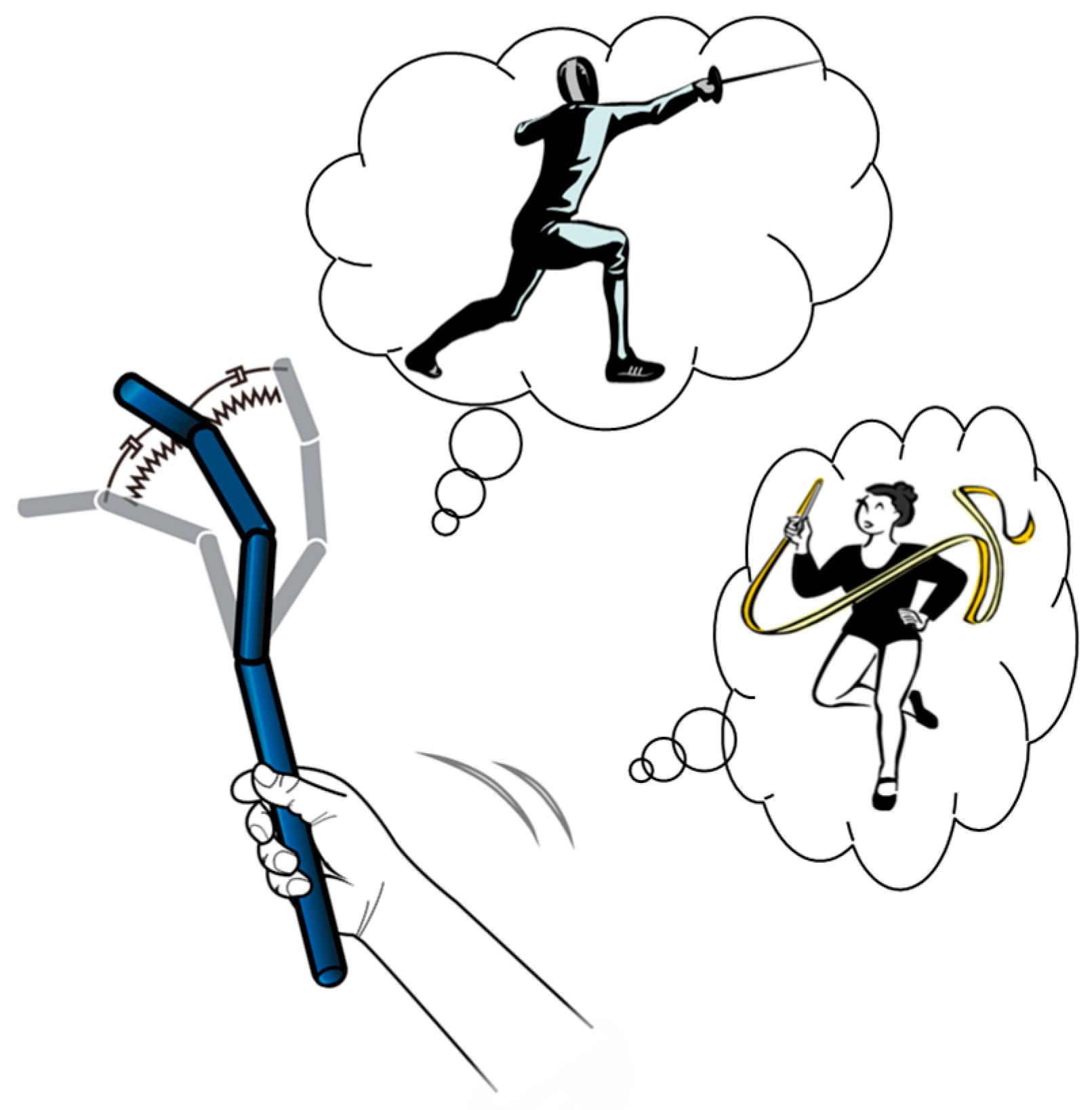
Real-life situations often involve touching a rigid object with a rod, leading to a deflection of certain mechanical properties. The rod deforms with respect to the user’s movement, according to its mechanical properties, such as stiffness and damping characteristics. These properties can be perceived as not only inertial forces, but also through the deflection behavior. Virtual reality systems likewise offer scenarios dealing with a variety of tools with different mechanical properties. If an interface system provides the deflection behavior of tools both graphically and physically, enhanced realism and immersion may be achieved. Based on this hypothesis, this paper proposes a mobile interface system to physically and graphically express a variety of tool characteristics (
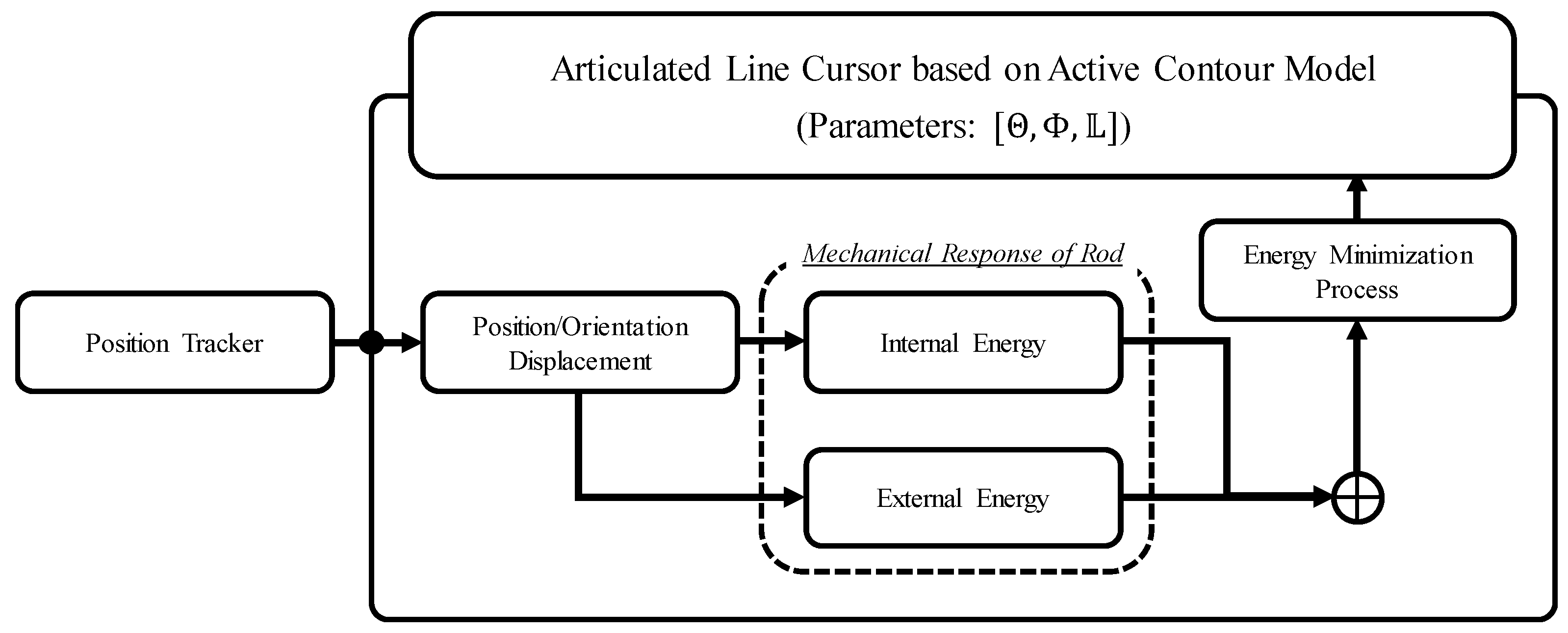
Figure 1). The system is composed of two parts; one is an algorithm that drives the interface system in a flexible manner, and the other is an articulated interface to visually represent this physical behavior.
The proposed method visualizes the physical behavior of the flexible rod according to the user’s position input. Hence, the algorithm should consider the time taken to reflect the user’s motion and to display on the virtual reality system, which is called motion-to-photon latency [
31]. To make the user feel the presence in the virtual environment, the value of motion-to-photon latency should not exceed 20 ms. Otherwise, it induces a poor virtual reality experience and may cause motion sickness. The physical rod can be modeled as a mass spring-based discretized model and finite element-based continuum model [
32]. Although the finite element-based model can achieve precise results, it requires a large computation time. Studies conducted in the past focused on developing a finite element analysis method to reduce the need for computation resources with increased precision [
33,
34,
35]. However, it is still difficult to obtain a sufficiently low value of motion-to-photon latency. Therefore, in this study, a physical rod is modeled to a mass spring-based discretized structure. Based on this structure, the proposed algorithm to generate the physical response is motivated by an active contour model that is an energy-based spline control method. It is a pseudo-physical model, capable of emulating the physical behavior of the rod. It can also be extended to a variety of scenarios such as geometric information transfer [
25] and affective interaction [
36,
37,
38] by assigning additional energy functionals. Based on this idea, a tool is modeled as a serial connection of line segments with torsional springs and dampers, and an energy functional describing deflection behavior is defined in terms of a user’s movement and the angular displacement of neighboring joints. Thus, the deflection behavior is represented by the joint rotation of each line segment. In the same manner, the proposed interface system can have each serial linkage joint actively rotated using an actuator. Therefore, flexibility of a rod can be represented as the rotation speed and phase difference of neighboring joints.
The proposed interface system operates as follows. The user grasps the bottom of the interface, and the position tracker follows the motion of the user. When displacement is detected, the trajectory of each joint is generated based on predefined mechanical characteristics, creating a joint trajectory for the proposed interface generated based on the user’s displacement.
3.2. Active Contour Model
To control each element of the line segments, an active contour model (also known as the snake algorithm) [
39] was employed as the baseline algorithm. The main purpose of a typical active contour model is to extract the contour of an object placed in an image. The model develops an energy-minimizing spline to determine the contour of the object. The total energy of the active contour model can be expressed as:
where
is the position of each element and s represents space parameters (e.g., the pixel position in image coordinates). The energy includes internal energy (
Eint) and external energy, which derives from the image features (
Eimage) and the external constraint energy (
Econ). The internal energy imposes piecewise smoothness among neighboring snake points. This can be calculated as:
where the subscript ‘
s’ represents a derivative with respect to ‘
s’, and
α and
β represent the weight of each derivative term. The first term represents the distance between neighboring elements, and the second term represents the curvature between elements. Depending on the weights, the spline acts like a membrane or thin plate. The external energy is responsible for pulling each element of the spline to the contour of the image. This energy was chosen since it relates to image contours such as lines and edges.
The position of spline elements at the local minimum of the energy functional satisfy the Euler-Lagrange equation:
Via iterative minimization, the snake elements gradually move towards the positions of the local minima of the energy functional. The minimization process is performed using an implicit Euler method as follows:
where
is the time step size and
is an inertial coefficient added to impose dynamic effects during the process. Equation (4) can be solved by matrix inversions as described below
As a result, the matrix that determines shape of the spline becomes a pentagonal matrix. If the internal energy parameters are set to constant, the matrix is also bisymmetric. Due to its sparse and symmetric properties, the energy of each element is effectively minimized and the number of the spline elements is easily modified.
3.3. Proposed Method
Our aim is to visualize the behavior of a rod with various physical properties both virtually and physically as described in the previous section.
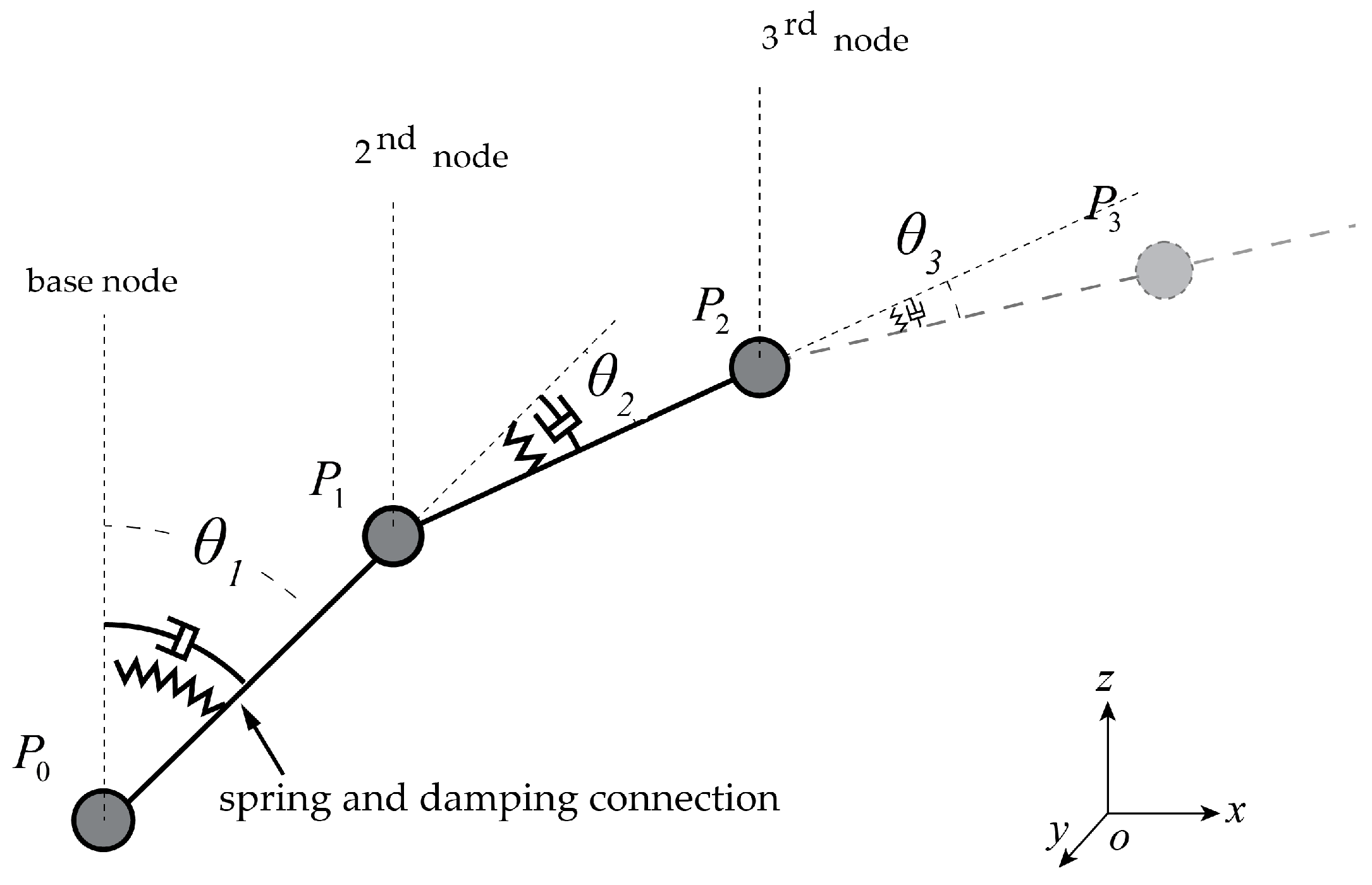
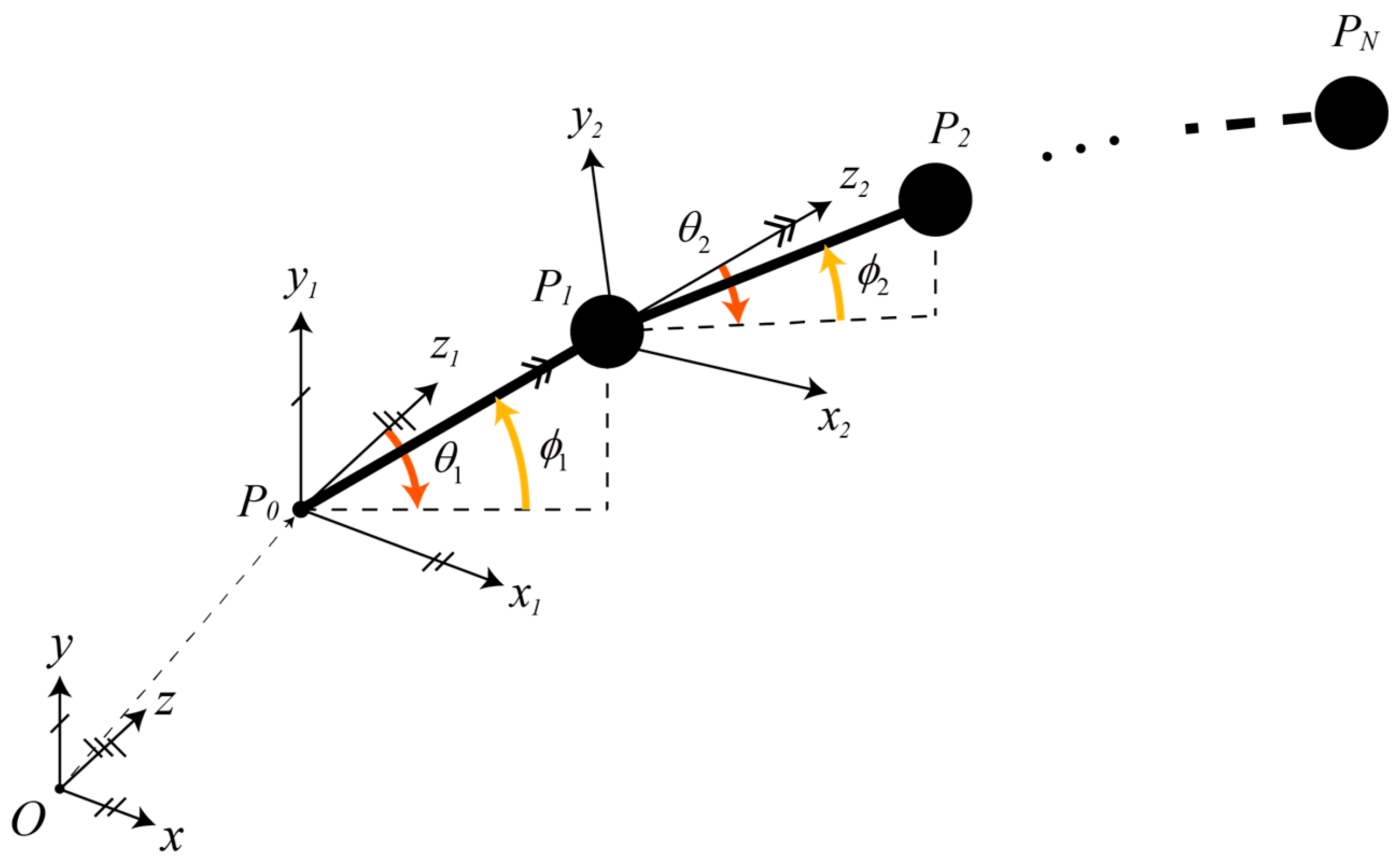
Figure 2 is a block diagram describing the proposed method. It is comprised of a position tracker that follows a user’s motion, and a computational algorithm using an active contour model to represent the rod’s behavior while following the user’s movement. The proposed method includes both graphics and linkage hardware, a geometric constraint to maintain the distance between neighboring elements as constant. To satisfy this constraint, we parameterized the contour in other coordinates to decouple the distance from the effect of the energy functional. In this paper, the spline is modeled in spherical coordinates, and is formed as a series of line segments with constant length (
Figure 3). In this configuration, the parameter value is defined as the angular displacement of previous nodes. Each line segment is parameterized as:
where
i is the number of the spline node, and the parameters
and
are the angles of rotation about the
x-axis and the
y-axis of each orientation
.
Based on this configuration, internal energy via the applied change is expressed in Equation (7), as
Since the proposed algorithm imposes the constant length constraint, the internal energy (Equation (2)) derived from the first derivative becomes zero. Since the spline is parameterized by angles, the second derivative becomes a first derivative. The external energy, which is capable of representing the physical behavior of a rod, is modelled as spring-damper connections between each of the neighboring line segments (
Figure 4). These energy functions were expressed as:
where
ks and
cd are coefficients that determine the spring and damping characteristics of each line segment. The external energy functional increases with the angular displacement from the previous spline element, and as its angular velocity increases. Therefore, every spline element becomes aligned with previous line segments having varying stiffness and damping properties.
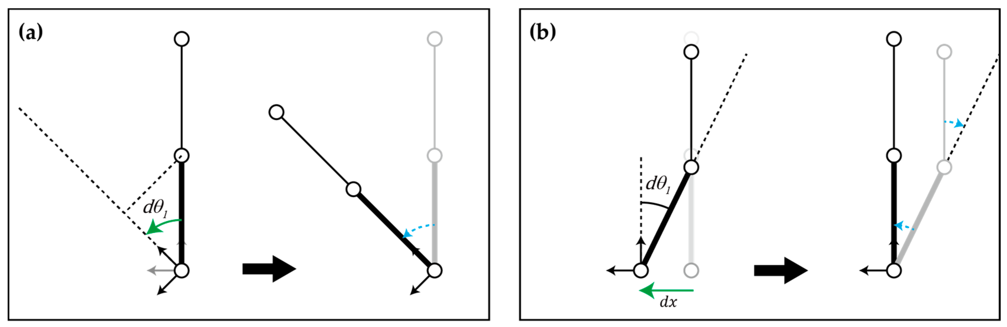
Applying a user’s positional input to the proposed spline requires changing the linear and rotation displacements by varying the parameter of the spline element (
Figure 5). These displacement values affect parameter values of first spline element which propagates through the spline element during the energy minimization process with the rotation displacement is correspond to orientation input. When a new orientation input occurs, the parametric variation is calculated based on angle between the line segment and axes of the orientation (
Figure 5a). It can be calculated as:
where
represents the first line segment vector in the input device coordinate of the subsequent step. In the case of linear displacement, the parametric variation is calculated by using the total derivative relation between the Cartesian and spherical coordinates (Equation (10)). As described in
Figure 5b from the linear displacement of the base element, the variation of parameter values occurs.
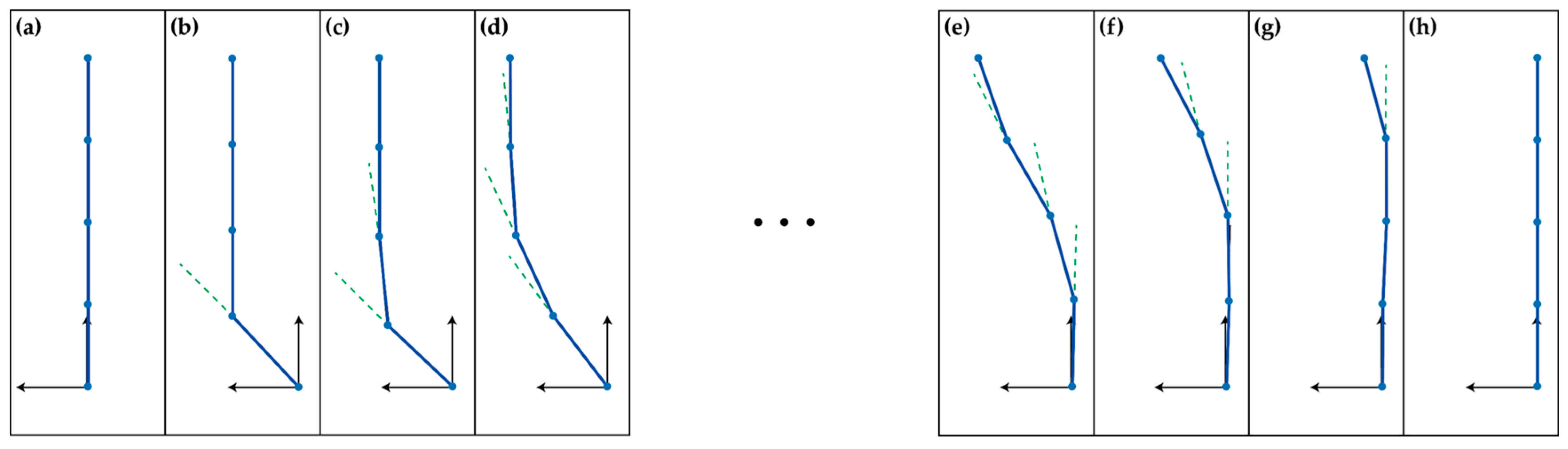
As a result, the spline with the proposed method operates as illustrated in
Figure 6. The translation and rotation of the base element caused by positional input induces an angular displacement of the first element according to Equations (9) and (10). These angular displacements affect the change of internal and external energies of entire line segments (Equations (6)–(9)). During energy minimization, the spline operates according to the defined physical parameters, and continues until the entire energy functional becomes zero. As a result, it reacts as a passively-moving object with mechanical properties. Note that only a single input (base position) is required to control the rest of the joints. The entire operation of the proposed method is also available in the
Supplementary Materials.
4. Analysis
As mentioned above, this paper proposes a computational algorithm to represent flexible characteristics with the joint angles of multiple line segments and can be achieved by modulating the stiffness and damping energy coefficients. To investigate its feasibility, the effect of changing the energy coefficient and positional input on the node responses was observed. Initially, the spline was constructed, comprised of four nodes, with each node modelled as 30 mm long with a mass of 0.2 kg. As the base element of the spline was moved by a user, its position was captured by an HTC Vive [
40], which is capable of tracking 3D positions and orientations. Although the proposed method can be applied to real-time applications, we used a recorded user’s input to compare the effect of the joint trajectories on the coefficients to understand the effect of energy coefficient modulation only. The recorded trajectory was of an arbitrary circular motion in 3D space, and was sampled at 100 Hz.
At first, we examined the computation time for the proposed method to obtain a low motion-to-photon latency. The computation time is measured from the time that the algorithm receives a new position input to the time taken to calculate the subsequent parameter values of the entire spline for next time step. It is measured under various condition such as type of trajectories and number of spline element. The average computation time according to input trajectories and number of spline element is represented in
Table 1. The computation time of the proposed method is affected by the number of the spline element only, and the maximum computation time is 2.5 ms when the number of spline elements is 50. Therefore, it can be shown that the proposed method does not require large computational resources and reliably reflects the user’s input to virtual the environment system without interfering low motion-to-photon latency.
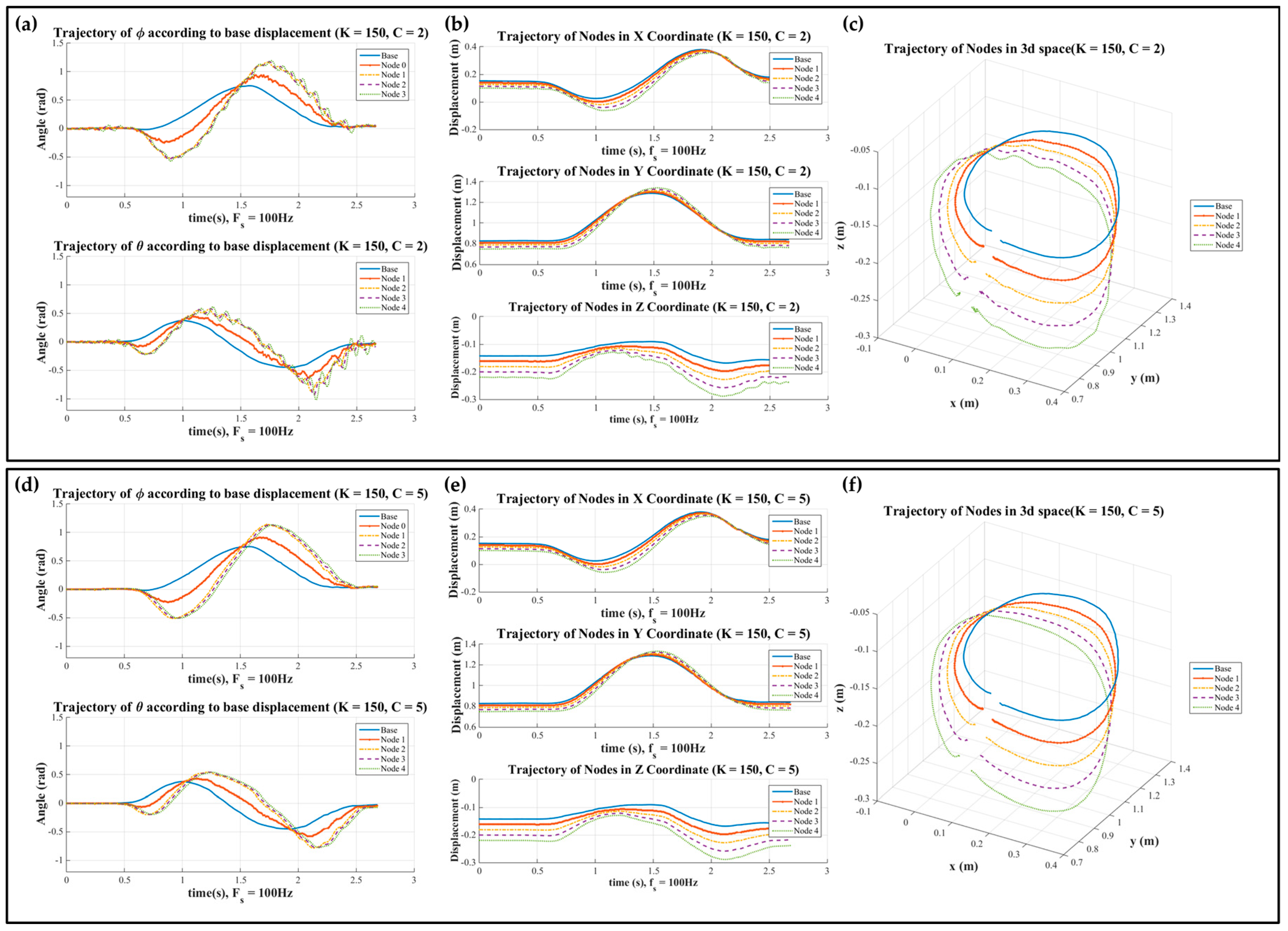
The modulation of these coefficients was performed in two ways, either by modulating the spring constants with a fixed damping constant, or by modulating the damping constant with a fixed spring constant. The responses of the spline while following the recorded trajectory are displayed in
Figure 7. These figures show the trajectories of the base element (blue solid line), parametric values of the spline elements as defined in spherical coordinates in (a), the trajectories of each spline element in Cartesian coordinates in (b), and in 3D space in (c), respectively. For the soft rod, with a small spring coefficient, a comparatively large angular displacement and phase delay were observed via the amplitudes of each node compared to the base node. Therefore, the entire spline had a large deflection, growing larger when nearing the rear of the nodes. For the stiff rod, however, the response was the opposite. Since it rapidly adapted to the angular displacement of previous elements, it showed a relatively smaller angular displacement and phase delay.
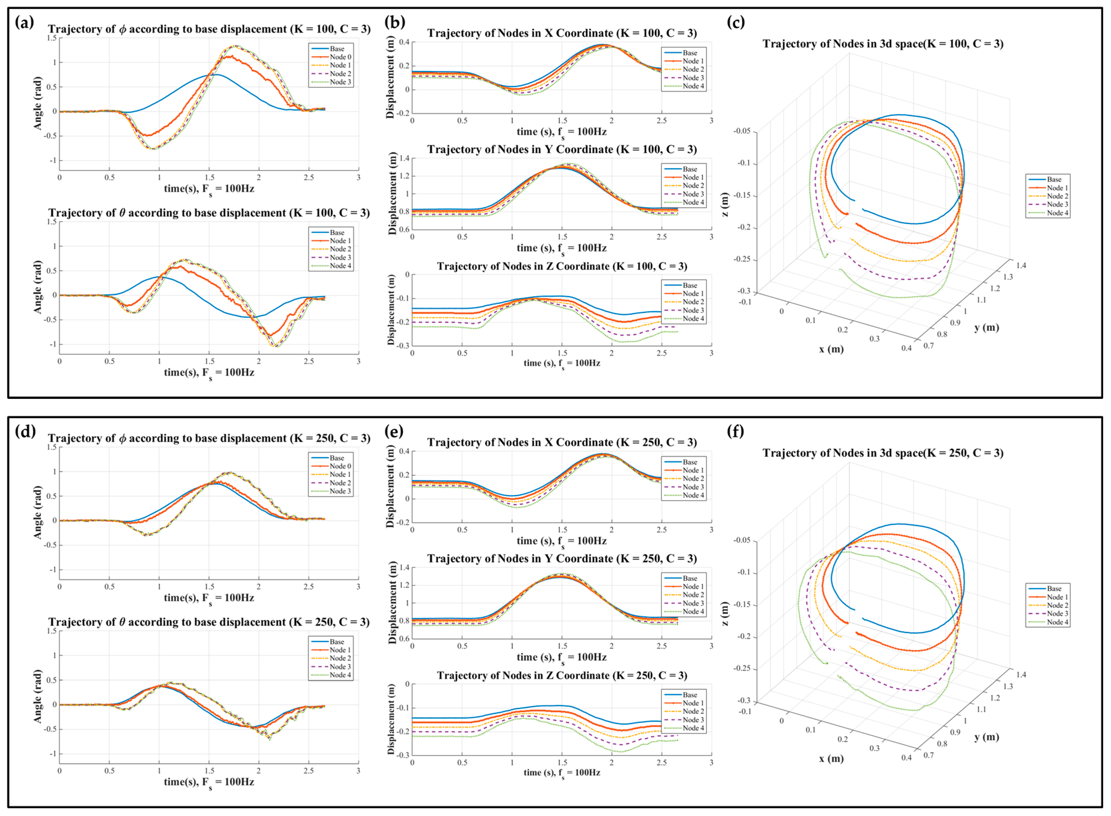
Figure 8 shows the response of the joints based on damping coefficient modulation. The modulation of damping did not affect the angular displacement or phase delay, but the smaller damping coefficients caused ripples during the process. In contrast, for high values of the damping coefficient, the joint angles converged to their rest position without ripples.
In this section, we analyzed the possibility of the proposed method to create various physical rod characteristics. To verify this, an analysis of the response generated by energy coefficient modulation was performed. This showed that the modulation of the spring coefficient effects the angular displacement and phase delay among neighboring nodes, while that of the damping coefficient effects the ripples during the response. Therefore, a variety of responses can be obtained by modulating these energy coefficients.
5. Application
Thus far, we described a novel method to imitate the behavior of a deformable rod with certain mechanical properties based on an active contour model. The proposed method can be applied to various interactive areas, including immersive 3D interaction, especially in augmented reality scenarios. Since the proposed interface can change its mechanical properties dynamically, it can be used by a variety of physical tools. This scenario can be applied to games, such as sword fighting, ribbon gymnastics, and other scenarios which deform its physical shape by directly reflecting the user’s position input. Furthermore, by representing the physical behavior in response to the other user’s position input, the proposed method can be applied to training scenarios conveying dynamic characteristics of the rod. The proposed method can also be extended to various interaction scenarios by defining additional energy functions according to a variety of task objects. For example, by defining an additional energy function to provide geometric information of a virtual object that a user contacts, the interface can lead the users to think that they are touching a virtual object with a deformable tool from the dynamic movement of each link. It can enhance the presence and performance of 3D manipulation tasks in augmented reality by providing enhanced spatial information of virtual objects [
23].
The proposed approach could also be applied to control graphical objects. The proposed model can generate trajectories of all spline elements while only measuring base positions. Hence, the method can be applied for the intuitive control of a graphic element that is composed of a series of line segments. For example, it could enhance the process of animation authoring by offering intuitive character control using the animator’s gestures. Note that the trajectory generation of 3D objects that are composed of multiple joints requires a great deal of time and cognitive load on the part of the animator [
41]. In fact, a previous effort by Shiratori et al. developed an efficient trajectory generation method based on an animator’s 3D gestures to resolve such issues [
42]. Placed in the same context, the method proposed herein can contribute to reducing the time and cost of animating tasks in that the phase and amplitude of each joint is determined only by the base position measurement, implying that an animator needs only to move a 3D positioning device around to simultaneously control the position of multiple joints, regardless of the number of joints.
6. Conclusions
In this paper, we proposed a novel shape-changing interface system to enhance the immersive experience in virtual reality environments. This interface is formed with a serially-linked interface, and its control algorithm is a modified active-contour model. It enables the representation of a tool’s mechanical properties that users handle in virtual and physical environments. By setting the external energy to the spring and damper constraints of each spline element, the proposed method can reflect the physical properties of a rod. One of the main advantages of our approach is that the model can generate joint trajectories of a serially-linked system that consist of multiple joints, based only on the position measurement of the base node, which is normally held by the user’s hand. It can also simulate a variety of flexible objects, such as a fencing sword or a whip, depending on the spring-damper parameters of the proposed algorithm. The proposed method can be applied to not only 3D interaction scenarios, but also to graphic element control, such as during the animation of 3D characters. In addition, it can be applied to other interaction scenarios by defining additional external energy functionals with respect to a user’s intention.
To validate the possibility of various response generation, we analyze the behavior of the spline element by modulating the external energy coefficient according to a user’s arbitrary position input. This showed that the proposed method can provide various responses depending on the external energy coefficients. In the future, we plan to systematically relate the parameter space to the user’s perception by conducting user tests.
Acknowledgments
This research project was supported by the Sports Promotion Fund of Seoul Olympic Sports Promotion Foundation from Ministry of Culture, Sports and Tourism.
Author Contributions
Seung-Chan Kim, and Dong-Soo Kwon conceived and designed the analysis; Byung-Kil Han performed the analysis; and Byung-Kil Han and Seung-Chan Kim wrote the paper.
Conflicts of Interest
The authors declare no conflict of interest.
References
- Hoffman, D.M.; Girshick, A.R.; Akeley, K.; Banks, M.S. Vergence–accommodation conflicts hinder visual performance and cause visual fatigue. J. Vis. 2008, 8, 33. [Google Scholar] [CrossRef] [PubMed]
- Robles-De-La-Torre, G. The importance of the sense of touch in virtual and real environments. IEEE Multimed. 2006, 13, 24–30. [Google Scholar] [CrossRef]
- Laycock, S.; Day, A. The haptic rendering of polygonal models involving deformable tools. In Proceedings of the EUROHAPTICS, Dublin, Ireland, 6–9 July 2003. [Google Scholar]
- Frohlich, B.; Tramberend, H.; Beers, A.; Agrawala, M.; Baraff, D. Physically-based manipulation on the responsive workbench. In Proceedings of the 2000 IEEE Virtual Reality, New Brunswick, NJ, USA, 22 March 2000; IEEE: New York, NY, USA, 2000; pp. 5–11. [Google Scholar]
- Salisbury, K.; Conti, F.; Barbagli, F. Haptic rendering: Introductory concepts. IEEE Comput. Graph. Appl. 2004, 24, 24–32. [Google Scholar] [CrossRef] [PubMed]
- Salisbury, K.; Brock, D.; Massie, T.; Swarup, N.; Zilles, C. Haptic rendering: Programming touch interaction with virtual objects. In Proceedings of the 1995 Symposium on Interactive 3D Graphics, Monterey, CA, USA, 9–12 April 1995; ACM: New York, NY, USA, 1995; pp. 123–130. [Google Scholar]
- Prattichizzo, D.; Pacchierotti, C.; Rosati, G. Cutaneous force feedback as a sensory subtraction technique in haptics. IEEE Trans. Haptics 2012, 5, 289–300. [Google Scholar] [CrossRef] [PubMed]
- Poupyrev, I.; Nashida, T.; Okabe, M. Actuation and tangible user interfaces: The vaucanson duck, robots, and shape displays. In Proceedings of the 1st International Conference on Tangible and Embedded Interaction, Baton Rouge, LA, USA, 15–17 February 2007; ACM: New York, NY, USA, 2007; pp. 205–212. [Google Scholar]
- Sato, M.; Hirata, Y.; Kawarada, H. Space interface device for artificial reality—spidar. Syst. Comput. Jpn. 1992, 23, 44–54. [Google Scholar] [CrossRef]
- Massie, T.H.; Salisbury, J.K. The phantom haptic interface: A device for probing virtual objects. In Proceedings of the ASME Winter Annual Meeting, Symposium on Haptic Interfaces for Virtual Environment and Teleoperator Systems, Chicago, IL, USA, 20 November 1994; pp. 295–300. [Google Scholar]
- Novint Technologies. Available online: http://www.novint.com/index.php/novintfalcon (accessed on 30 November 2017).
- Ho, C.-H.; Basdogan, C.; Srinivasan, M.A. Haptic rendering: Point-and ray-based interactions. In Proceedings of the Second PHANToM Users Group Workshop, Dedham, MA, USA, 19–22 October 1997. [Google Scholar]
- Zilles, C.B.; Salisbury, J.K. A constraint-based god-object method for haptic display. In Proceedings of the 1995 IEEE/RSJ International Conference on Intelligent Robots and Systems 95 ‘Human Robot Interaction and Cooperative Robots’, Pittsburgh, PA, USA, 5–9 August 1995; IEEE: New York, NY, USA, 1995; pp. 146–151. [Google Scholar]
- Laycock, S.D.; Day, A. A survey of haptic rendering techniques. In Computer Graphics Forum; Wiley Online Library: Hoboken, NJ, USA, 2007; pp. 50–65. [Google Scholar]
- Rosenberg, L.B. Virtual fixtures: Perceptual tools for telerobotic manipulation. In Proceedings of the 1993 IEEE Virtual Reality Annual International Symposium, Seattle, WA, USA, 18–22 September 1993; IEEE: New York, NY, USA, 1993; pp. 76–82. [Google Scholar]
- Abbott, J.; Marayong, P.; Okamura, A. Haptic virtual fixtures for robot-assisted manipulation. In Robotics Research; Springer: Berlin/Heidelberg, Germany, 2007; pp. 49–64. [Google Scholar]
- Kim, H.; Kim, M.; Lee, W. Hapthimble: A wearable haptic device towards usable virtual touch screen. In Proceedings of the 2016 CHI Conference on Human Factors in Computing Systems, San Jose, CA, USA, 7–12 May 2016; ACM: New York, NY, USA, 2016; pp. 3694–3705. [Google Scholar]
- Minamizawa, K.; Fukamachi, S.; Kajimoto, H.; Kawakami, N.; Tachi, S. Gravity grabber: Wearable haptic display to present virtual mass sensation. In Proceedings of the ACM SIGGRAPH 2007 Emerging Technologies, San Diego, CA, USA, 5–9 August 2007; ACM: New York, NY, USA, 2007; p. 8. [Google Scholar]
- Benko, H.; Holz, C.; Sinclair, M.; Ofek, E. Normaltouch and texturetouch: High-fidelity 3d haptic shape rendering on handheld virtual reality controllers. In Proceedings of the 29th Annual Symposium on User Interface Software and Technology, Tokyo, Japan, 16–19 October 2016; ACM: New York, NY, USA, 2016; pp. 717–728. [Google Scholar]
- Winfree, K.N.; Romano, J.M.; Gewirtz, J.; Kuchenbecker, K.J. Control of a high fidelity ungrounded torque feedback device: The itorqu 2.1. In Proceedings of the 2010 IEEE International Conference on Robotics and Automation (ICRA), Anchorage, AK, USA, 3–7 May 2010; IEEE: New York, NY, USA, 2010; pp. 1347–1352. [Google Scholar]
- Badshah, A.; Gupta, S.; Morris, D.; Patel, S.; Tan, D. Gyrotab: A handheld device that provides reactive torque feedback. In Proceedings of the SIGCHI Conference on Human Factors in Computing Systems, Austin, TX, USA, 5–10 May 2012; ACM: New York, NY, USA, 2012; pp. 3153–3156. [Google Scholar]
- Rasmussen, M.K.; Pedersen, E.W.; Petersen, M.G.; Hornbæk, K. Shape-changing interfaces: A review of the design space and open research questions. In Proceedings of the SIGCHI Conference on Human Factors in Computing Systems, Austin, TX, USA, 5–10 May 2012; ACM: New York, NY, USA, 2012; pp. 735–744. [Google Scholar]
- Iwata, H.; Yano, H.; Nakaizumi, F.; Kawamura, R. Project feelex: Adding haptic surface to graphics. In Proceedings of the 28th Annual Conference on Computer Graphics and Interactive Techniques, Los Angeles, CA, USA, 12–17 August 2001; ACM: New York, NY, USA, 2001; pp. 469–476. [Google Scholar]
- Follmer, S.; Leithinger, D.; Olwal, A.; Hogge, A.; Ishii, H. Inform: Dynamic physical affordances and constraints through shape and object actuation. In Proceedings of the UIST, St Andrews, UK, 8–11 October 2013; pp. 417–426. [Google Scholar]
- Bordegoni, M.; Ferrise, F.; Covarrubias, M.; Antolini, M. Geodesic spline interface for haptic curve rendering. IEEE Trans. Haptics 2011, 4, 111–121. [Google Scholar] [CrossRef] [PubMed]
- Klare, S.; Peer, A. The formable object: A 24-degree-of-freedom shape-rendering interface. IEEE/ASME Trans. Mechatron. 2015, 20, 1360–1371. [Google Scholar] [CrossRef]
- Katsumoto, Y.; Tokuhisa, S.; Inakage, M. Ninja track: Design of electronic toy variable in shape and flexibility. In Proceedings of the 7th International Conference on Tangible, Embedded and Embodied Interaction, Barcelona, Spain, 10–13 February 2013; ACM: New York, NY, USA, 2013; pp. 17–24. [Google Scholar]
- Nakagaki, K.; Dementyev, A.; Follmer, S.; Paradiso, J.A.; Ishii, H. Chainform: A linear integrated modular hardware system for shape changing interfaces. In Proceedings of the 29th Annual Symposium on User Interface Software and Technology, Tokyo, Japan, 16–19 October 2016; ACM: New York, NY, USA, 2016; pp. 87–96. [Google Scholar]
- Nakagaki, K.; Follmer, S.; Ishii, H. Lineform: Actuated curve interfaces for display, interaction, and constraint. In Proceedings of the 28th Annual ACM Symposium on User Interface Software & Technology, Charlotte, NC, USA, 11–15 November 2015; ACM: New York, NY, USA, 2015; pp. 333–339. [Google Scholar]
- Nakagaki, K.; Inamura, C.; Totaro, P.; Shihipar, T.; Akikyama, C.; Shuang, Y.; Ishii, H. Linked-stick: Conveying a physical experience using a shape-shifting stick. In Proceedings of the 33rd Annual ACM Conference Extended Abstracts on Human Factors in Computing Systems, Seoul, Korea, 18–23 April 2015; ACM: New York, NY, USA, 2015; pp. 1609–1614. [Google Scholar]
- Abrash, M. What VR Could, Should, and Almost Certainly Will Be within Two Years; Steam Dev Days: Seattle, WA, USA, 2014. [Google Scholar]
- Gibson, S.F.; Mirtich, B. A Survey of Deformable Modeling in Computer Graphics; Technical Report; Mitsubishi Electric Research Laboratories: Cambridge, MA, USA, 1997. [Google Scholar]
- Guessasma, S.; Hamdi, A.; Lourdin, D. Linear modelling of biopolymer systems and related mechanical properties. Carbohydr. Polym. 2009, 76, 381–388. [Google Scholar] [CrossRef]
- Huang, J.; Ong, S.-K.; Nee, A.Y. Real-time finite element structural analysis in augmented reality. Adv. Eng. Softw. 2015, 87, 43–56. [Google Scholar] [CrossRef]
- Guessasma, S.; Benseddiq, N.; Lourdin, D. Effective young’s modulus of biopolymer composites with imperfect interface. Int. J. Solids Struct. 2010, 47, 2436–2444. [Google Scholar] [CrossRef]
- Park, Y.-W.; Park, J.; Nam, T.-J. The trial of bendi in a coffeehouse: Use of a shape-changing device for a tactile-visual phone conversation. In Proceedings of the 33rd Annual ACM Conference on Human Factors in Computing Systems, Seoul, Korea, 18–23 April 2015; ACM: New York, NY, USA, 2015; pp. 2181–2190. [Google Scholar]
- Togler, J.; Hemmert, F.; Wettach, R. Living interfaces: The thrifty faucet. In Proceedings of the 3rd International Conference on Tangible and Embedded Interaction, Cambridge, UK, 16–18 February 2009; ACM: New York, NY, USA, 2009; pp. 43–44. [Google Scholar]
- Park, J.; Park, Y.-W.; Nam, T.-J. Wrigglo: Shape-changing peripheral for interpersonal mobile communication. In Proceedings of the SIGCHI Conference on Human Factors in Computing Systems, Toronto, ON, Canada, 26 April–1 May 2014; ACM: New York, NY, USA, 2014; pp. 3973–3976. [Google Scholar]
- Kass, M.; Witkin, A.; Terzopoulos, D. Snakes: Active contour models. Int. J. Comput. Vision 1988, 1, 321–331. [Google Scholar] [CrossRef]
- HTC. Htc Vive. Available online: https://www.vive.com (accessed on 5 April 2016).
- Jacobson, A.; Panozzo, D.; Glauser, O.; Pradalier, C.; Hilliges, O.; Sorkine-Hornung, O. Tangible and modular input device for character articulation. ACM Trans. Graph. TOG 2014, 33, 82. [Google Scholar]
- Shiratori, T.; Mahler, M.; Trezevant, W.; Hodgins, J.K. Expressing animated performances through puppeteering. In Proceedings of the 2013 IEEE Symposium on 3D User Interfaces (3DUI), Orlando, FL, USA, 16–17 March 2013; IEEE: New York, NY, USA, 2013; pp. 59–66. [Google Scholar]
© 2018 by the authors. Licensee MDPI, Basel, Switzerland. This article is an open access article distributed under the terms and conditions of the Creative Commons Attribution (CC BY) license (http://creativecommons.org/licenses/by/4.0/).


