Ultrathin Terahertz Dual-Band Perfect Metamaterial Absorber Using Asymmetric Double-Split Rings Resonator
by
Taiguo Lu
1,2, 
Dawei Zhang
1,*,
Peizhen Qiu
1,
Jiqing Lian
1,
Ming Jing
1,
Binbin Yu
1 and
Jing Wen
1 1
Engineering Research Center of Optical Instrument and System, Ministry of Education and Shanghai Key Laboratory of Modern Optical System, University of Shanghai for Science and Technology, Shanghai 200093, China
2
School of Physical Science and Information Engineering, Liaocheng University, Liaocheng, Shandong 252059, China
*
Author to whom correspondence should be addressed.
Symmetry 2018, 10(7), 293; https://doi.org/10.3390/sym10070293
Submission received: 7 June 2018
/
Revised: 1 July 2018
/
Accepted: 16 July 2018
/
Published: 20 July 2018
(This article belongs to the Special Issue Broken Symmetry)
Abstract
:In this article, an ultrathin terahertz dual band metamaterial absorber made up of patterned asymmetrical double-split rings and a continuous metal layer separated by a thin FR-4 layer is designed. Simulation results show that two almost identical strong absorption peaks appear in the terahertz band. When the incident electric field is perpendicular to the ring gaps located at 11 μm asymmetrically, the absorptivity of 98.6% at 4.48 THz and 98.5% at 4.76 THz can be obtained. The absorption frequency and the absorptivity of the absorber can be modulated by the asymmetric distribution of the gaps. The perfect metamaterial absorber is expected to provide important reference for the design of terahertz modulator, filters, absorbers, and polarizers.
1. Introduction
Metamaterials have aroused considerable research interests in the past decades, owing to their unique properties that cannot be found in nature materials [1]. Since their unusual properties were demonstrated theoretically and experimentally [2,3], metamaterials have greatly improved many novel inventions, taking the place of classical devices such as surperlenses [4,5], antennas [6,7], filters [8], sensors, and other devices [9,10].
Landy et al. provided the first experimental demonstration of metamaterial perfect absorbers in 2008 [11]. Since then metamaterials have been used extensively to make absorbers because of their unique characteristics that are different from the conventional ones. For example, we can modulate the absorption frequencies and absorptivity by changing the parameters of the unit cell. It is generally known that absorbing characteristics of the conventional absorbers are determined by natural properties of the bulk materials [12]. Based on these benefits, many metamaterial perfect absorbers have been widely studied and successfully used, such as bolometers [13], chemical and biomedical sensing [14], photodetector [15], photothermal conversion [16], and so on.
Terahertz multi-band metamaterial resonators made up of different split ring resonators (SRRs) or crosses have been proposed [17,18,19,20,21,22,23]. Magnetic or electric resonance responses appear at the terahertz frequency in sub-wavelength SRRs [24,25]. Some asymmetric metamaterials with different shapes demonstrated different characteristics from that of symmetric metamaterials, which can be used to develop novel devices working in the terahertz band, such as filtering, modulating, and switching the electromagnetic signal [26,27]. Tao H. et al. reported a dual-band metamaterial absorber, there are two absorption peaks, but one of these two absorption peaks is strong and the other is weak [28]. Wen et al. improved the structure to get two distinct and strong absorption peaks, they used a complex symmetric structure [29]. Yang et al. studied the propagation properties of a planar asymmetric metamaterial composed of double split-ring resonators, they discovered a giant amplitude modulation as the symmetry of the unit cell resonator is broken by changing the two gaps position asymmetrically [30]. A terahertz wave perfect absorber with the identical strong dual band absorption is urgently needed, but as far as we know it is still lacking to date.
In this work, we report on an enhanced ultrathin perfect absorber that has the following crucial advantages. First, our designed absorber is of ultrathin structure, which is simple and is formed by only a patterned double-split ring with two gaps displaced asymmetrically in opposite directions and a spacer FR-4 layer on top of a continuous metal layer. Secondly, there are two almost equal strong absorption peaks. When the incident electric field vector is perpendicular to the ring gaps located at 11 μm asymmetrically, the absorptivity of 98.6% at 4.48 THz and 98.5% at 4.76 THz can be obtained. Lastly, we can achieve modulating of the absorption frequency and the absorptivity by changing the parameters of the unit cell. The asymmetric metamaterial absorber is expected to be used as a cloaking material and filter devices in the THz range.
2. Design and Simulation
The absorber is designed and its properties are simulated by the software CST Microwave Studio (2016, Computer Simulation Technology GmbH). It is crucial that the SRRs and the free space can maintain the same impedance by adjusting the parameters of the unit cell in order to get the lowest reflectivity. Therefore the structure is simulated and optimized using the simulation software. The optimal parameters of the designed absorber are obtained by changing and scanning all the proposed parameters.
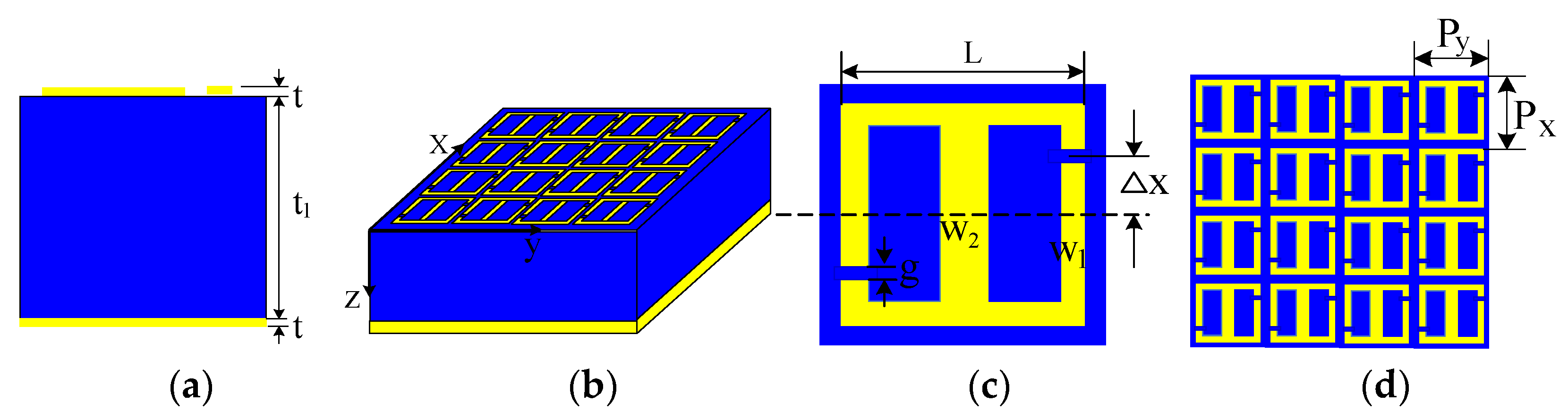
Figure 1 shows the schematic of the designed absorber. We can see from Figure 1a,b that the proposed absorber is made up of three layers: a continuous metal layer on the bottom, a dielectric spacer layer, and finally a metal patterned layer with double split-ring unit cells periodically arranged on the top. We use a continuous metallic copper layer as the bottom layer, as the bottom continuous copper layer has a thickness much larger than the skin depth of the incident terahertz wave. The wave is totally reflected by the continuous metallic copper layer, the transmission amplitude should be zero in the THz frequency range [31]. The thickness of the metal copper on the top and bottom layers with a conductivity of 4.58 × 10⁷ S/m is 0.036 μm and the thickness of the FR-4 layer with a real permittivity of 4.3 and a loss tangent of 0.025 is optimized to 7 μm.
The unit cell consists of two same connecting half split-ring resonators (SRRs) with the two gaps displayed asymmetrically in opposite directions, as shown in Figure 1c. The dimensions of the SRRs are optimized as L = 36 μm, the linewidth of the side arms W1 = 2 μm, the linewidth of the middle arm W2 = 4 μm, the width of the gaps g = 2 μm and the periodicity of SRRs is 40 μm in the x and y axis, as shown in Figure 1d.
The appropriate boundary condition is adopted, such as the periodic condition in both the x and y axis and the open (add space) boundary condition in the z axis. The incident wave propagating along the z axis is set to be polarized in the x axis and the wave ports are automatically added.
3. Results and Discussions
A calculation of the absorptivity of the absorber is performed. The absorptivity A can be obtained by A = 1 − T − R, where T denotes the transmissivity and R denotes the reflectivity. However, in this design, the transmissivity T should be zero, as previously described: A is simplified as A = 1 − R. Therefore, the absorptivity is only related to the reflectivity. In order to achieve the minimum reflectivity, the impedance of the absorb should be matched to that of free space ().
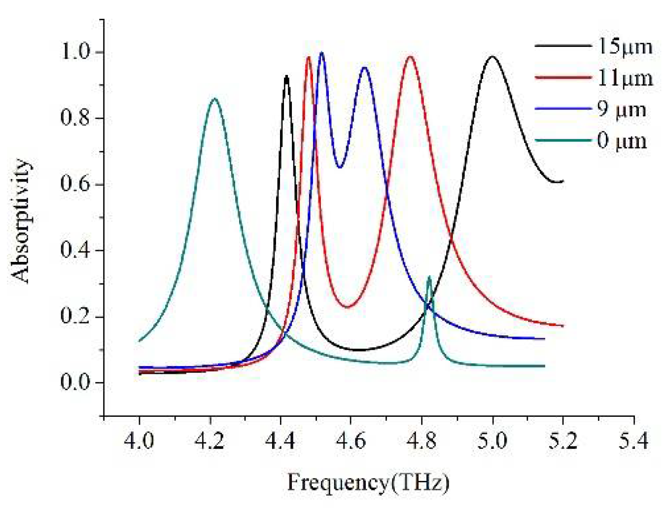
The asymmetric double split-ring array is designed to observe asymmetric effects by breaking the symmetry. Asymmetry in the double split-ring unit cell is introduced by locating the gaps in the opposite direction, keeping the same distance from the center at = 0, 9, 11, 15 μm, respectively, as shown in Figure 2, where represents the gaps displacement parameter. The results show that the absorption frequency and the peak value varying with the gaps position distributed asymmetrically in the 4.0–5.2 THz range.
We compare the results when the gaps are displayed in the opposite direction at = 0, 9, 11, 15 μm. It can be seen from Figure 2 that the calculated absorptivity is 85.8% at the low-frequency and 32.1% at the high-frequency, when = 0, respectively. The interval between the two absorption frequencies is reduced when = 9 μm, which is similar to the literature [32]. It is no wonder that when = 11 μm, there are two separated absorption peaks with high absorption (98.5% at the low-frequency 4.48 THz and 98.6% at the high-frequency 4.76 THz). The two absorption peaks are almost equal only when the gaps were located at 11 μm asymmetrically. The absorption bandwidth, usually defined as full width at half maximum (FWHM), is 0.06 at the lower-frequency. In contrast, FWHM broadens significantly at a high-frequency, increasing from 0.06 at 4.48 THz to 0.18 at 4.76 THz. The corresponding quality factor Q (the ratio of the resonance frequency and the FWHM) is 75 and 26, respectively. The quality factor Q is a very important parameter, an excessively high Q indicates a strong frequency selectivity, due to the narrow absorption bandwidth.
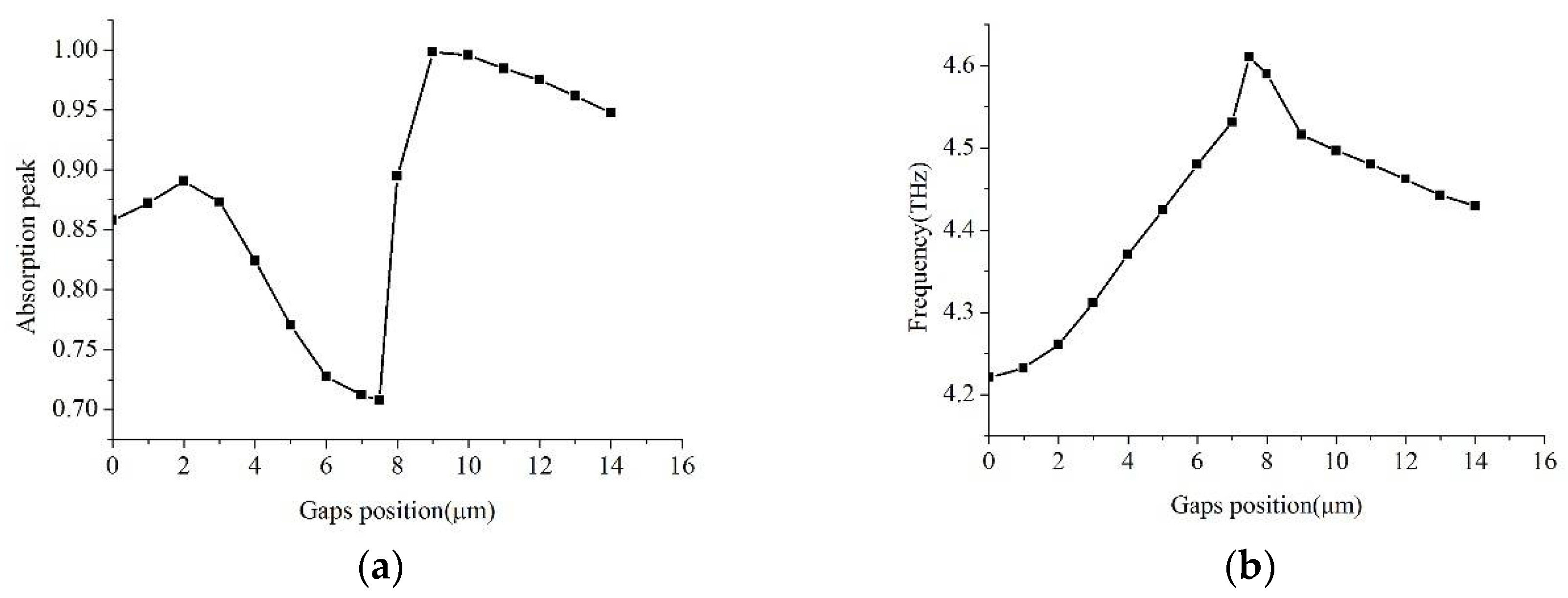
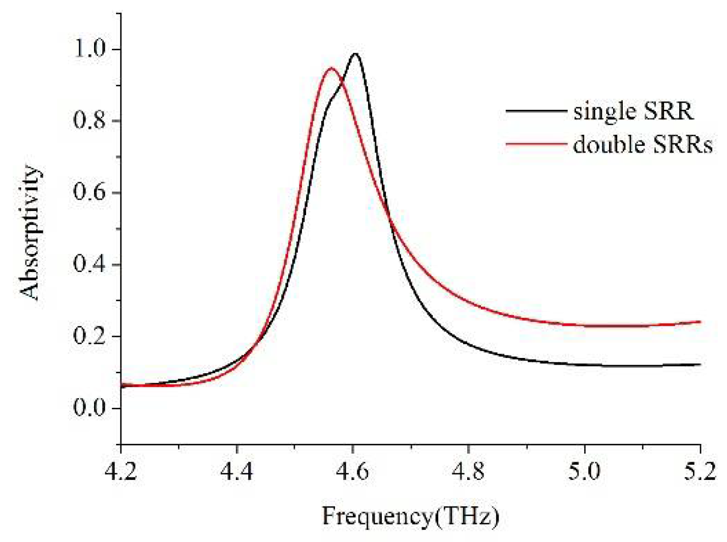
We analyze the change of the absorption frequency and the absorption peak at low-frequency with the varying of the gaps position. Figure 3a shows the varying of the absorption frequency at low-frequency as a function of the gaps position with different distances away from the center. This indicates that the absorption frequency increases with increasing and then decreases after reaching its maximum value 4.61 THz at = 7.5 μm. The absorption peak changes with the gaps position varying, and the absorption peak reaches its minimum at = 7.5 μm, as can be seen from Figure 3b. Another important result is produced when = 7.5 μm, there is only one absorption peak, as can be seen from Figure 4. As for the comparison, if the absorption spectrum of a single SRR is observed, the two conclusions are in good agreement. However, the change of the resonance frequency and absorptivity as a function of the gaps position at a high frequency is more complex because of the coupling between the SRRs.
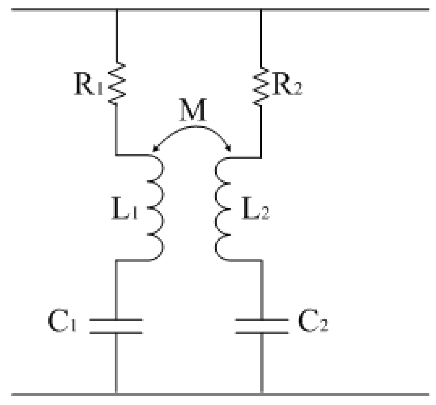
In order to comprehend the absorption characteristics of the perfect absorption deeply at low-frequency and high-frequency with the gaps displaced at different place away from the center, Figure 5 shows the schematic: the absorber can be treated as an inductor-capacitor circuit according to the equivalent theory. The resonant frequency of the single LC circuit is calculated by Equation (1)
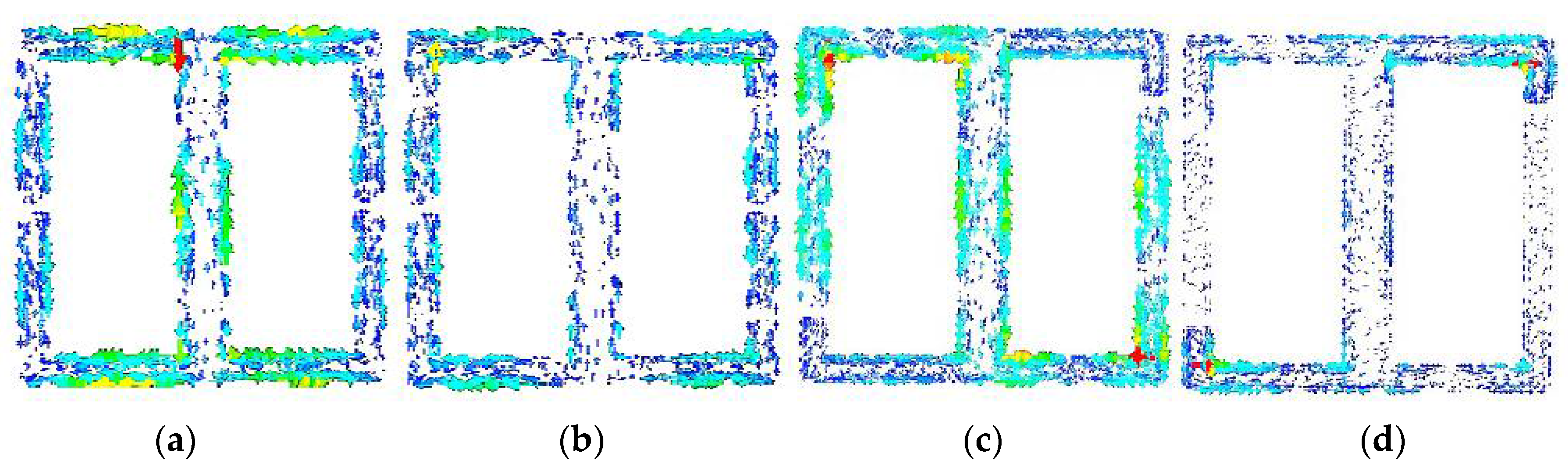
In Equation (1) the parameters L and C represent the effective inductance and the effective capacitance respectively. Ideally, the parameter L is related to the area and geometry of the metal arm and the parameter C is related to the geometry of the split gap. M denotes the coupling parameter, for M = 0, there is no coupling between the two SRRs. As an example, when = 7.5 μm, there is only one absorption frequency; it has almost the same absorptivity and resonance center frequency as the single SRR, shown in Figure 4. When M departs from zero, the coupling effect on the overall response is most drastic. The mutual coupling leads to absorption frequency splitting and changing absorption peaks. In order to better understand the physical mechanism of the resonances occurring, the surface current distribution is studied numerically. Figure 6a,c depict the surface induction current of the SRRs, it is found that there are strong current oscillations at the low-frequency directly excited by the incident terahertz field whether it is in a symmetric or asymmetric case. The current direction is the same on both sides of the SRR gap in the symmetric case and opposite in the asymmetric case. The current length is different when is different, which relates to the resonance frequency and the absorption peak. While the surface current on the all vertical arms is small at the high-frequency in asymmetric case shown in Figure 6b,d. The excited fields from one of the SRRs induce an opposite direction surface current in another SRR, thus leading to the suppressed currents in the SRRs [33]. The induced current in all the arms will lead to a variety of magnetic responses in the system, which cause the splitting and shifting of the LC resonance frequency and variety of the absorption amplitude. The overlapping of the two fundamental LC resonances and the mutual coupling of the dipolar lead to the two strong absorption peaks. At the same time, with increasing asymmetry, the incident linear polarized beam was converted into an elliptically polarized beam at the LC resonance. The component of the incident electric field along the x and y axis is different, which leads to different resonance peak values. The larger the parameter Δx, the more x-polarized the field converting into the y-component [34]. When the polarization of the incident wave is along the x axis, there is only one absorption peak. And as the incident angle changes, the absorption frequency and absorption peak will also change. Thus the polarization and incident angle depending on one another can be a drawback on the application. However, the polarization and incident angle not depending on one another may be achieved by reasonable arrangement of the asymmetry structure to the symmetrical structure [35].
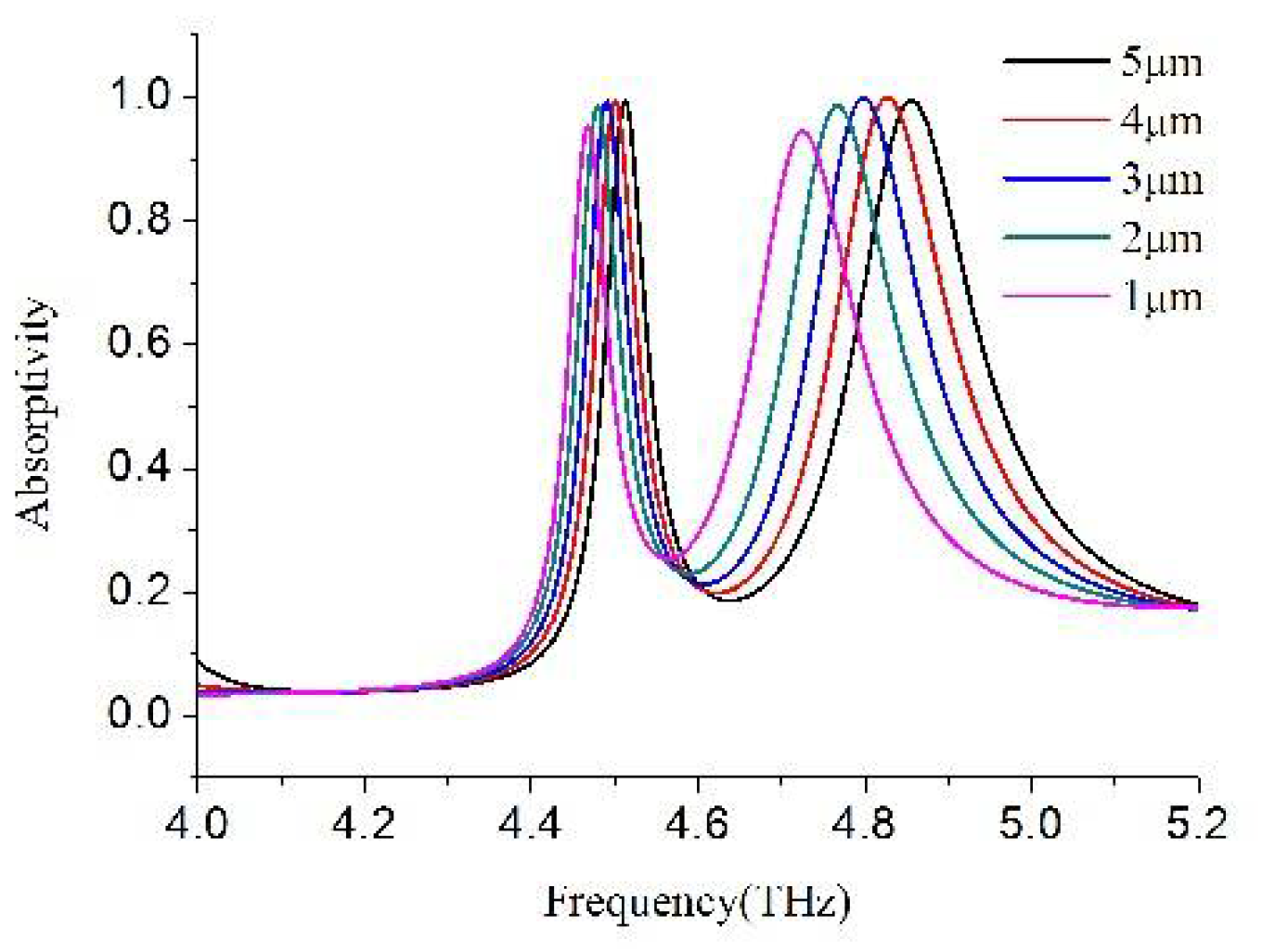
4. The Effects of the Width of the Gaps and the Middle Arm
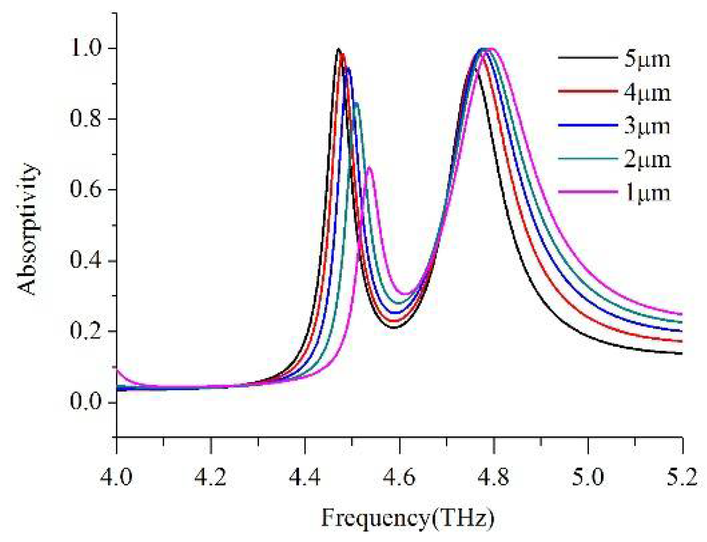
We study the absorptivity varying with the different gaps width (g). We carry out simulations for different gaps width parameters with gaps located at 11 μm away from the center respectively. Figure 7 shows a clear blue-shift from 4.73 to 4.86 THz for the high-frequency with the increasing width of the gaps from 1 to 5 μm in the asymmetric case, whereas there is little movement for the low-frequency. The shift can be well explained using the LC resonance of the SRRs. According to Equation (1), L and C determine the resonance frequency in the SRRs, the capacitance C will decrease when the width of the gaps increase and the frequency will increase accordingly. The coupling between the two SRRs plays a key role and enlarges the result and leads to an obvious shift at the high-frequency. We find that we can modulate the resonance frequency at high-frequency by changing the width of the gaps. In order to investigate the effect of the middle arm on the metamaterial resonances while varying the width of middle arm, we carry out a series of simulations varying the width of middle arm from 1 to 5 μm with the gaps located at 11 μm away from the center. Figure 8 shows representative absorption spectra for the different widths of the middle arm in the asymmetric case, increasing the middle arm width leads to a red shift of the resonance frequency at the low-frequency, which has almost no effect on the frequency shift at the high-frequency. It is obvious that the low-frequency resonant excitation is mainly derived from the middle arm. When the width is 4 μm, two times of the side arm of the SRRs, the resonance peak is equal at the two resonance frequencies. When the width is smaller than that of the frame of the SRRs, the resonance peak is smaller at the low-frequency than at the high- frequency. The change of the width of the middle arm effects the coupling between the SRRs; we can modulate the resonance frequency and the absorption peak by changing the width of the middle arm.
5. Conclusions
In summary, we propose an ultrathin terahertz dual band metamaterial absorber made up of asymmetric double SRRs that has two strong absorptions, 98.6% at 4.48 THz and 98.5% at 4.76 THz, respectively. The changing of the resonant frequency and the absorptivity is demonstrated numerically and is theoretically explained. The resonant frequency and the absorptivity are related to the LC resonance of the metamaterial and are affected by the mutual coupling. The absorption frequency and the absorptivity can be modulated by optimizing the corresponding width of the gaps and the width of the middle arm in the asymmetric case. The advantage of the design can be used to provide improved device functions such as modulator, filters, absorbers, and polarizers in the terahertz band and other frequency bands as well.
Author Contributions
T.L. put forward the idea of the work and was in charge of writing. D.Z. was the research consultant and coordinator. P.Q. and J.L. devoted to data analysis and the revision of the article. M.J., B.Y. and J.W. committed to the simulation.
Funding
This research was funded by the National Natural Science Foundation of China [No. 61775140].
Acknowledgments
The authors would like to thank anonymous reviewers and the editors for their helpful and constructive suggestions that improved this paper.
Conflicts of Interest
The authors declare no conflict of interest.
References
- Lan, C.; Bi, K.; Li, B.; Cui, X.; Zhou, J.; Zhao, Q. Hyperbolic metamaterial based on anisotropic Mie-type resonance. Opt. Express 2013, 21, 29592–29600. [Google Scholar] [CrossRef] [PubMed]
- Pendry, J.B.; Holden, A.J.; Robbins, D.J.; Stewar, W.J. Magnetism from conductors and enhanced nonlinear phenomena. IEEE Trans. Microw. Theory Tech. 1999, 47, 2075–2084. [Google Scholar] [CrossRef] [Green Version]
- Smith, D.R.; Padilla, W.J.; Vier, D.C.; Nemat-Nasser, S.C.; Schultz, S. Composite medium with simultaneously negative permeability and permittivity. Phys. Rev. Lett. 2000, 84, 4184. [Google Scholar] [CrossRef] [PubMed]
- Pendry, J.B. Negative refraction makes a perfect lens. Phys. Rev. Lett. 2000, 85, 3966–3969. [Google Scholar] [CrossRef] [PubMed]
- Fang, N.; Zhang, X. Imaging properties of a metamaterial superlens. Appl. Phys. Lett. 2003, 82, 161–163. [Google Scholar] [CrossRef]
- Hwang, R.B.; Liu, H.W.; Chin, C.Y. A metamaterial-based E-plane horn antenna. Prog. Electromagn. Res. 2009, 93, 275–289. [Google Scholar] [CrossRef]
- Islam, M.M.; Islam, M.T.; Samsuzzaman, M.; Faruque, M.R.I. Compact metamaterial antenna for UWB applications. Electron. Lett. 2015, 51, 1222–1224. [Google Scholar] [CrossRef]
- Lu, M.; Li, W.; Brown, E.R. Second-order bandpass terahertz filter achieved by multilayer complementary metamaterial structures. Opt. Lett. 2011, 36, 1071–1073. [Google Scholar] [CrossRef] [PubMed]
- Melik, R.; Unal, E.; Perkgoz, N.K.; Puttlitz, C.; Demir, H.V. Metamaterial-based wireless strain sensors. Appl. Phys. Lett. 2009, 95, 011106. [Google Scholar] [CrossRef] [Green Version]
- Schurig, D.; Mock, J.J.; Justice, B.J.; Cummer, S.A.; Pendry, J.B.; Starr, A.F.; Smith, D.R. Metamaterial electromagnetic cloak at microwave frequencies. Science 2006, 314, 977–980. [Google Scholar] [CrossRef] [PubMed]
- Landy, N.I.; Sajuyigbe, S.; Mock, J.J.; Smith, D.R.; Padilla, W.J. Perfect metamaterial absorber. Phys. Rev. Lett. 2008, 100, 207402. [Google Scholar] [CrossRef] [PubMed]
- Smith, D.R.; Vier, D.C.; Koschny, T.; Soukoulis, C.M. Electromagnetic parameter retrieval from inhomogeneous metamaterials. Phys. Rev. E 2005, 71, 036617. [Google Scholar] [CrossRef] [PubMed]
- Savinov, V.; Fedotov, V.A.; de Groot, P.A.; Zheludev, N.I. Radiation-harvesting resonant superconducting sub-THz metamaterial bolometer. Supercond. Sci. Technol. 2013, 26, 084001. [Google Scholar] [CrossRef]
- Singh, L.; Xie, L.; Chen, M.; Xu, N.; Singh, R.; Zhang, W. Terahertz sensing of highly absorptive water-methanol mixtures with multiple resonances in metamaterials. Opt. Express 2017, 25, 14089–14097. [Google Scholar]
- Gu, Y.; Kwak, E.S.; Lensch, J.L.; Allen, J.E.; Odom, T.W.; Lauhon, L.J. Near-field scanning photocurrent microscopy of a nanowire photodetector. Appl. Phys. Lett. 2005, 87, 043111. [Google Scholar] [CrossRef]
- Yang, J.; Huang, M.; Yang, C.; Peng, J.; Zong, R. Metamaterial electromagnetic super absorber with arbitrary geometries. Energies 2010, 3, 1335–1343. [Google Scholar] [CrossRef]
- Tao, H.; Landy, N.I.; Bingham, C.M.; Zhang, X.; Averitt, R.D.; Padilla, W.J. A metamaterial absorber for the terahertz regime: Design, fabrication and characterization. Opt. Express 2008, 16, 7181–7188. [Google Scholar] [CrossRef] [PubMed]
- Yuan, Y.; Bingham, C.; Tyler, T.; Palit, S.; Hand, T.H.; Padilla, W.J.; Jokerst, N.M.; Cummer, S.A. A dual-resonant terahertz metamaterial based on single-particle electric-filed-couple resonators. Appl. Phys. Lett. 2008, 93, 1991110. [Google Scholar] [CrossRef]
- Zhang, W.; Li, W.; Chang, S. A thermally tunable terahertz metamaterial absorber. Optoelectron. Lett. 2015, 11, 18–21. [Google Scholar] [CrossRef]
- Kollatou, T.M.; Dimitriadis, A.I.; Assimonis, S.D.; Kantartzis, N.V.; Antonopoulos, C.S. Mulit-Band, Highly Absorbing, Microwave Metamaterial Structures. Appl. Phys. A 2014, 115, 555–561. [Google Scholar] [CrossRef]
- Li, H.; Yuan, L.H.; Zhou, B.; Shen, X.; Cheng, P.Q.; Cui, T.J. Ultrathin multiband gigahertz metamaterial absorbers. J. Appl. Phys. 2011, 110, 014909. [Google Scholar] [CrossRef]
- Sun, J.; Liu, L.; Dong, G.; Zhou, J. An extremely broad band metamaterial absorber based on destructive interference. Opt. Express 2011, 19, 21155–21162. [Google Scholar] [CrossRef] [PubMed]
- Manjappa, M.; Chiam, S.Y.; Cong, L.; Bettiol, A.A.; Zhang, W.; Singh, R. Tailoring the slow light behavior in terahertz metasurfaces. Appl. Phys. Lett. 2015, 106, 181101. [Google Scholar] [CrossRef] [Green Version]
- Bingham, C.; Tao, M.H.; Liu, X.; Averitt, R.D.; Zhang, X.; Padilla, W.J. Planar wallpaper group metamaterials for novel terahertz applications. Opt. Express 2008, 16, 18565–18575. [Google Scholar] [CrossRef] [PubMed]
- Tao, H.; Strikwerda, A.C.; Fan, K.; Padilla, W.J.; Zhang, X.; Averitt, R.D. Reconfigurable Terahertz Metamaterials. Phys. Rev. Lett. 2009, 103, 147401. [Google Scholar] [CrossRef] [PubMed]
- Akosman, A.E.; Serebryannikov, A.E.; Ozbay, E.; Mutlu, M. Asymmetric chiral metamaterial circular polarizer based on four U-shaped split ring resonators. Opt. Lett. 2011, 36, 1653–1655. [Google Scholar]
- Singh, R.; Alnaib, I.A.; Koch, M.; Zhang, W. Asymmetric planar terahertz metamaterials. Opt. Soc. Am. 2010, 18, 13044–13050. [Google Scholar] [CrossRef] [PubMed]
- Tao, H.; Bingham, C.M.; Strikwerda, A.C.; Pilon, D.; Shrekenhamer, D.; Landy, N.I.; Fan, K.; Zhang, X.; Padilla, W.J.; Averitt, R.D. Highly flexible wide angle of incidence terahertz metamaterial absorber: Design, fabrication, and characterization. Phys. Rev. B 2008, 78, 1879–1882. [Google Scholar] [CrossRef]
- Wen, Q.Y.; Zhang, H.W.; Xie, Y.S.; Yang, Q.H.; Liu, Y.L. Dual band terahertz metamaterial absorber: Design, fabrication, and characterization. Appl. Phys. Lett. 2009, 95, 241111. [Google Scholar] [CrossRef]
- Yang, Y.; Huang, R.; Cong, L.; Zhu, Z.; Gu, J.; Tian, Z.; Singh, R.; Zhang, S.; Han, J.; Zhang, W. Modulating the fundamental inductive-capacitive resonance in asymmetric double-split ring terahertz metamaterials. Appl. Phys. Lett. 2011, 98, 121114. [Google Scholar] [CrossRef]
- Seo, M.A.; Park, H.R.; Koo, S.M.; Park, D.J.; Kang, J.H.; Suwal, O.K.; Choi, S.S.; Planken, P.C.M.; Park, G.S.; Park, N.K.; et al. Terahertz field enhancement by a metallic nano slit operating beyond the depth limit. Nat. Photonics 2009, 3, 152–156. [Google Scholar] [CrossRef]
- Lee, J.; Lim, S. Bandwidth-enhanced and polarization-insensitive metamaterial absorber using double resonance. Electron. Lett. 2011, 47, 8–9. [Google Scholar] [CrossRef]
- Li, Z.; Ma, Y.; Huang, R.; Singh, R.; Gu, J.; Tian, Z.; Han, J.; Zhang, W. Manipulating the plasmon-induced transparency in terahertz metamaterials. Opt. Express 2011, 19, 8912–8919. [Google Scholar] [CrossRef] [PubMed]
- Zang, X.F.; Liu, S.J.; Cheng, Q.Q.; Xie, J.Y.; Zhu, Y.M.; Wang, Y.J. Lower-ordersymmetry induced bandwidth controllable terahertz polarization converter. J. Opt. 2017, 19, 115103. [Google Scholar] [CrossRef]
- Li, T.Q.; Liu, H.; Li, T.; Wang, S.M.; Cao, J.X.; Zhu, Z.H.; Dong, Z.G.; Zhu, S.N.; Zhang, X. Suppression of radiation loss by hybridization effect in two coupled split-ring resonators. Phys. Rev. B 2009, 80, 115113. [Google Scholar] [CrossRef]
Figure 1.
Ultrathin terahertz dual band metamaterial absorber. (a) Side view of the unit cell structure with t1 = 7 μm, t = 0.036 μm; (b) Perspective view of the absorber; (c) The front view of the the unit cell with optimized parameters of L = 36 μm, W1 = 2 μm, W2 = 4 μm, g = 2 μm; (d) Periodic structure of the unit cell with Px = Py = 40 μm.

Figure 2.
Simulated absorptivity for the split ring resonators (SRRs) with various distance of the gaps away from the center.
Figure 2.
Simulated absorptivity for the split ring resonators (SRRs) with various distance of the gaps away from the center.

Figure 3.
The resonance frequency (a) and the absorption peak (b) as a function of gaps position at low-frequency.
Figure 3.
The resonance frequency (a) and the absorption peak (b) as a function of gaps position at low-frequency.

Figure 4.
Absorptivity of the single SRR and the double SRRs with = 7.5 μm, respectively.

Figure 5.
Equivalent circuit representation for the SRRs.

Figure 6.
Simulated surface induction current at (a) = 0; (c) = 11 μm at low-frequency and (b) = 0 μm; (d) = 11 μm at high-frequency respectively.
Figure 6.
Simulated surface induction current at (a) = 0; (c) = 11 μm at low-frequency and (b) = 0 μm; (d) = 11 μm at high-frequency respectively.

Figure 7.
Simulated absorptivity as a function of the frequency for the various width of the gaps, with the gaps displaced 11 μm asymmetrically.
Figure 7.
Simulated absorptivity as a function of the frequency for the various width of the gaps, with the gaps displaced 11 μm asymmetrically.

Figure 8.
Simulated absorptivity as a function of frequency for various widths of the middle arm with the gaps displaced 11 μm asymmetrically.
Figure 8.
Simulated absorptivity as a function of frequency for various widths of the middle arm with the gaps displaced 11 μm asymmetrically.

© 2018 by the authors. Licensee MDPI, Basel, Switzerland. This article is an open access article distributed under the terms and conditions of the Creative Commons Attribution (CC BY) license (http://creativecommons.org/licenses/by/4.0/).
Share and Cite
MDPI and ACS Style
Lu, T.; Zhang, D.; Qiu, P.; Lian, J.; Jing, M.; Yu, B.; Wen, J. Ultrathin Terahertz Dual-Band Perfect Metamaterial Absorber Using Asymmetric Double-Split Rings Resonator. Symmetry 2018, 10, 293. https://doi.org/10.3390/sym10070293
AMA Style
Lu T, Zhang D, Qiu P, Lian J, Jing M, Yu B, Wen J. Ultrathin Terahertz Dual-Band Perfect Metamaterial Absorber Using Asymmetric Double-Split Rings Resonator. Symmetry. 2018; 10(7):293. https://doi.org/10.3390/sym10070293
Chicago/Turabian StyleLu, Taiguo, Dawei Zhang, Peizhen Qiu, Jiqing Lian, Ming Jing, Binbin Yu, and Jing Wen. 2018. "Ultrathin Terahertz Dual-Band Perfect Metamaterial Absorber Using Asymmetric Double-Split Rings Resonator" Symmetry 10, no. 7: 293. https://doi.org/10.3390/sym10070293
Note that from the first issue of 2016, this journal uses article numbers instead of page numbers. See further details here.