Symmetric Shape Transformations of Folded Shell Roofs Determining Creative and Rational Shaping of Building Free Forms

Department of Architectural Design and Engineering Graphics, Rzeszow University of Technology, Al. Powstańców Warszawy 12, 35-959 Rzeszów, Poland
*
Author to whom correspondence should be addressed.
Symmetry 2019, 11(12), 1438; https://doi.org/10.3390/sym11121438
Submission received: 30 September 2019
/
Revised: 14 November 2019
/
Accepted: 20 November 2019
/
Published: 22 November 2019
(This article belongs to the Special Issue Selected Papers: Symmetry 2019—The Second Edition of the International Conference on Symmetry)
Abstract
:The paper presents an innovative approach to solving interdisciplinary problems emerging in the design process of building free forms roofed with elastically transformed corrugated shells. The effectiveness and rationality of shaping such free forms and the creativeness in searching for the parametric forms require the application of their regular and symmetric models which have to be derived from the geometric and mechanical properties of the rationally transformed subsequent folds of these shells. Simplified smooth models used for engineering developments and accurate folded models implemented for scientific research have to be created by means of unconventional methods different from those presented in classical courses. Owing to the variety of the forms of the proposed innovative reference tetrahedrons and their parametric description, the algorithms developed by the authors have to be implemented in computer programs. The rationality of the transformed roof shells, revealed in the limitation of the level of the fold’s initial stresses resulting from the shape transformation, and the attractiveness of these forms are achieved by the axial symmetry and contraction of each shell fold at its half-length. The symmetries adopted in the process of modeling such roof shells are also exploited by the discussed new method to obtain coherent unconventional general forms of entire buildings.
1. Introduction
Single or double-curvature vaults and roof shells have been used since the Gothic era. Complete and complex curved metal shell roofs appeared and became very popular in the Renaissance due to their attractive architectural forms and stable constructions [1,2,3]. Nowadays, space grids and complete shells are combined into various consistent shell structures to achieve large internal column-free spaces, strengthen the shell roof constructions, and improve their stability [4,5,6]. Laminated glass shells made of reinforced polymers are employed as members in building constructions to increase the attractiveness and simplicity of the architectural free forms [7,8].
In order to obtain a corrugated steel roof shell (Figure 1), nominally flat sheets folded in one direction can be connected with their longitudinal edges into one strip and then transformed into a spatial shape [9]. Such an operation is performed when the strip is spread on two skew directrices so that the transverse edges of this strip pass along the directrices.
If all folds of such a strip are provided with freedom of their transverse shape deformations, thus allowing the folds to freely adapt their shape to the arbitrary directrices, a relatively large continuous range of various shell forms can be achieved depending on the shape and mutual position of these directrices. A particular feature of the subsequent shell folds of the transformed strip is their tendency to maintain symmetrical forms with a contraction passing halfway along the length of each transformed fold [10]. The shape transformations are effective because they allow the designed shell roof forms to maintain the smallest possible pre-stress and give them the ability to carry live loads despite large cross-sectional deformations and mutual displacements of the subsequent folds in a corrugated shell roof.
In order to obtain special, innovative, attractive and rational forms of roof shells and their structural systems [11,12], the designer has a relatively large amount of freedom in using the effective shape transformations for engineering purposes. Diversified symmetrical arrangements of directrices, entire roof shells, entire building free forms and their structural systems can be employed effectively [13] (Figure 2).
In such a transformed shell, the longitudinal axes of each transformed fold and two opposite longitudinal straight edges of each fold in the shell are skew straight lines. Therefore, each effectively transformed corrugated shell can be modeled with a smooth sector of a regular warped surface [14,15] with a satisfactory accuracy for engineering developments. The border of the section is a closed spatial quadrangle, whose two opposite sides modeling the directrices are curved or straight sections, while the other two are sections modeling two straight longitudinal edges of the shell [10].
2. State of the Art
The transformed folded shells are most often formed as central sectors of hyperbolic paraboloids [16] (Figure 3) or quarters of the sectors arranged symmetrically in different configurations [17] (Figure 4). The geometrical and mechanical properties of the thin-walled folded hyperbolic-paraboloid shells, which are called hypars, have been investigated by such researchers as Winter, Fisher, Edger and Resinger [17], Gergely, Banavalkar and Parker [18], Brayan and Davis [19], and Petcu and Gioncu [20]. However, all of the investigated shells had undergone irrational forced shape transformations, allowing them to only obtain shallow shells.
Adam Reichhart has shaped corrugated shell roofs that have been freely transformed, as he called them, because he thought that the investigated type of the shape transformations does not affect large unnecessary pre-stresses (Figure 2). Reichhart’s concept consists of modeling the subsequent transformed shell folds with the right hyperbolic paraboloids [13]. However, he did not formulate the condition regarding the equilibrium state of a freely transformed shell fold, resulting in the location of the contraction of the fold and the entire transformed shell. He did not define a sufficient number of quantities describing the shape of the shell fold for the case when its longitudinal axis is not perpendicular to the directrices. Thus, Reichhart’s method is only useful and accurate for engineering developments in the cases when the axes of all folds in the transformed shell are perpendicular to the adopted directrices or really close to perpendicular [11].
Abramczyk showed [11,21] that the Reichhart algorithm does not provide the freedom of the fold’s shape changes resulting from the shape transformations. The lack of symmetry and wrong positions of the contraction of the fold’s smooth models in many cases are the effect of Reichhart’s method, which results in the differentiation of the form and effort of both transverse ends of the same fold.
In order to create an accurate method of shaping the considered transformed shells, Abramczyk has proposed a condition requiring the contraction of the entire shell to pass halfway along the length of each shell fold, which ensures the effectiveness of the transformations used. This condition exploits some specific geometrical properties of ruled undevelopable surfaces called warped surfaces, primarily their lines of striction. The other condition employed relates to calculations of the surface areas of the created smooth shell models. Both conditions are based on the results of the experimental tests presented in his doctoral thesis [9].
3. Aims
The aim of the paper is to present the applicability of the authors’ method used for the effective geometric and static-strength shaping of buildings characterized by attractive, symmetric, architectural free forms and roofed with steel shells made up of many nominally flat folded thin-walled sheets of open profiles. The diversified roof shell systems of these sheets can be obtained by connecting them by their longitudinal edges into one continuous folded strip, followed by their elastic and rational transformation into spatial corrugated shell forms characterized by the smallest possible pre-stress to transfer roof live loads.
The authors have observed the need to use various kinds of symmetry because of the many issues they have encountered in their research related to geometric, architectural and static-strength shaping of buildings characterized by unconventional architectural free forms. One of the most important favorite effects of using symmetry is the visual attractiveness of the designed transformed roof shells [22,23].
4. Concept
The implementation of the adopted aim requires a discussion of creating simplified, smooth models of corrugated shell roofs obtained by elastic transformations of nominally flat, thin-walled, rectangular steel sheets profiled in one direction and connected by longitudinal edges into a single continuous folded strip. These models should be characterized by a high visual attractiveness of their spatial shell forms, resulting also from their unconventional forms and symmetry. In addition, the innovative symmetrical forms of the ruled shell roofs should affect the attractiveness of the unconventional architectural free forms of entire buildings, and lead to the rationality and efficiency of their structural systems.
The one-directional corrugation of a nominally flat sheet enables one to achieve large deformations of its folds in directions transverse to the longitudinal axes of these folds. Thus, it is necessary to examine significant changes of the fold’s widths and the mutual position of the adjacent folds in the sheet achieved with the help of a very small force acting perpendicularly to the plane of the sheet in order to adapt the sheet’s shape to the mutual location and shape of two skew directrices.
The process of accurate modeling and rational structural shaping of such transformed shell sheeting is significantly complicated by the fact that the above deformations and displacements are different along each single fold and often for subsequent folds in the sheeting. However, due to the diversity, it is possible to shape the diversified unconventional shapes of the transformed shell roofs. The achieved unconventional corrugated shell forms of roofs whose folds have straight axes and straight longitudinal edges are a positive visual result of the effective sheet’s transformations. A pre-stress induced by these transformations is the negative effect, but the effective transformations enable the shell folds to preserve sufficient capacity to carry live loads (Figure 5).
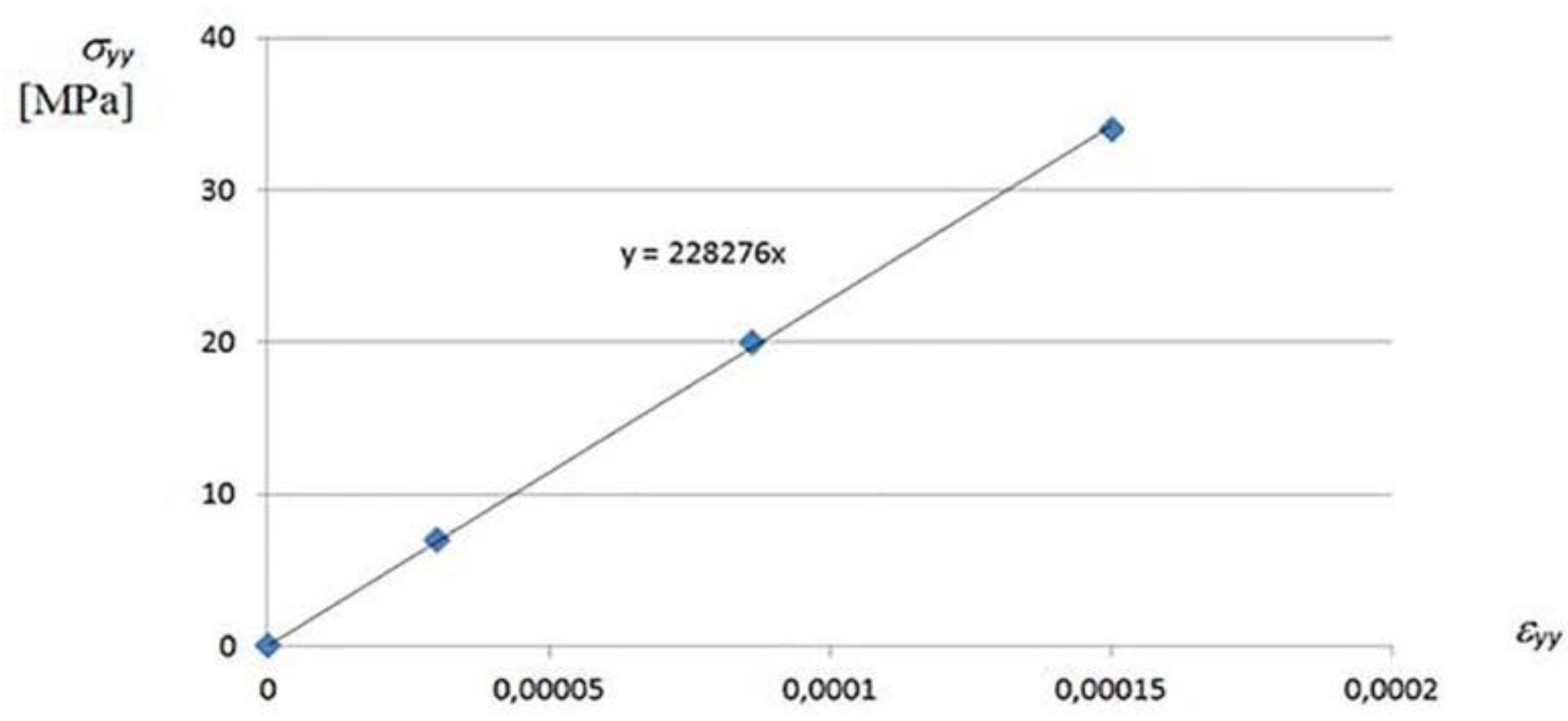
During the authors’ tests [9,21], linear constitutive relations were observed for all types of stresses including the one presented in Figure 6.
Therefore, the following linear constitutive relations can be employed [24]:
where
[σ] = [E] ([ε] − [ε0])
- [σ] = —Vector of stresses, [ε] = —Vector of strains,
- [ε] = , —Vector of nodal displacements,
- [E] = ; c = E/[], G = E/2,
- [ε0] = —Vector of initial strains produced by the increment of temperature, here [ε0] =
where σz = τzx = τxz = τyx = τyz 0, [E] is the matrix of elastic stiffness, and v is Poisson’s ratio.
To obtain the generalized displacements of the adopted nodes, the following equilibrium of generalized nodal forces has to be satisfied [24]:
where [R] is the vector of applied nodal loads, [F] is the vector of nodal forces and moments, [D] is the solution vector of displacements (translations and rotations), [Ke] is the symmetrical mechanical element stiffness matrix, and [Ge] is the symmetrical geometrical element stiffness matrix.
[F] = ([Ke] + [Ge]) ∙ [D] − [R]
To obtain formulas for the element stiffness matrix, load vector, strain vector and body forces vector, the principle of virtual work must be satisfied. It is based on interpolation of generalized displacements referring to nodal degrees of freedom and requires relatively simple calculations. The principle of virtual work can be expressed as [13]:
where [δε] is the vector of strains, [δu] is the virtual displacement, [F] is the body forces in volume V, and [Ф] is the tractions on surface S.
Because the effective initial shape transformations are used to obtain transformed corrugated roof shells, then large displacements and rotations are applied but small strains are achieved. During experimental tests, linear constitutive relations were observed in the examined range of the total twist of each shell fold, so total Lagrangian (TL) formulation, second Piola–Kirchoff stress, and Green–Lagrange stain, as well as dynamics methods, were employed [25].
The classical Newton–Raphson technique was implemented to realize the incremental iteration method used in finite element analysis. This method is used to calculate an incremen Δt [ΔD(i)] in the nodal point displacement, a new modified total displacement vector the incremental solution t+Δt[D](i) at time t + Δt in iteration i, instead of the previous one at time [D](i), and then t calculated during iteration i − 1. The two equations that accomplished the Newton–Raphson iteration are as follows [26]:
t+Δt[K](i−1) [ΔD(i)] = t+Δt[R] − t+Δt[F](i−1)
t+Δt[D](i) = t+Δt[D](i−1) + [ΔD(i)]
In materially nonlinear analysis, only the following equations are employed:
- (a)
- In static analysis:t[K] [D] = t+Δt[R] − t[F]
- (b)
- In dynamic analysis:[M] t+Δt[D″] + t[K] [D] = t+Δt[R] − t[F]
However, if we use the TL formulation, the following conditions are used:
- (a)
- In static analysis:(t[KL] + t[KNL]) [D] = t+Δt[R] − t[F]
- (b)
- In dynamic analysis:[M] t+Δt[D′′] + (t[KL] + t[KNL]) = t+Δt[R] − t[F]
where [M] is the time-independent matrix, t[K] is the linear strain incremental stiffness matrix, t[KL] is the linear strain incremental stiffness matrix, t[KNL] is the nonlinear strain incremental stiffness matrix, t+Δt[R] is the vector of externally applied nodal point loads at time t + Δt, t[F] is the vector of nodal point forces referring to the element stresses at time t, [D] is the vector of increments in the nodal points displacements, and t+Δt[D″] is the vector of nodal point accelerations at times t and t + Δt.
If a freedom of the transverse deformations of a transformed strip, including its width increments, are ensured during the spreading of the strip on directrices, then the elastic shape transformation of this strip is effective. This efficiency consists of obtaining the smallest possible pre-stress of all shell folds caused by the shape transformation, and allows the sheeting to maintain sufficient capacity to transfer the roof’s service loads. The effective transformation usually results in symmetrical forms of the designed corrugated roof shells and their complete folds [9] (Figure 7a,b, Figure 8, Figure 9 and Figure 10), and leads to a balance of the internal forces in the transformed sheets after spreading these sheets on the directrices [21] (Figure 5).
The diagrams presented in Figure 7a,b show the size of the relative width increments of three folds (n = 1 to 3) of the same tested folded sheet, measured along seven transverse measuring lines (i = 1 to 7) uniformly distributed on the top surface of the sheet’s folds (see Figure 8 and Figure 9). The folded geometric model of an effectively transformed sheet is shown in Figure 8, where the longitudinal lines vj,a are the edges of these three folds (j = n = 1 to 3), and ui,a represent transverse measuring lines (i = 1 to 7). The scheme of the arrangement of the above edge and measuring lines is presented in Figure 9.
From Figure 7a, we can read that both edge folds (n = 1 and 3) change their widths identically to each other at their entire length. In Figure 7b, we can see that each of the folds (n = 1 to 3) changes the width on its length symmetrically relative to the central measuring line (i = 4 = x). From both diagrams, we can deduce the symmetric nature of the shape changes at the length and width of the effectively transformed folded sheet.
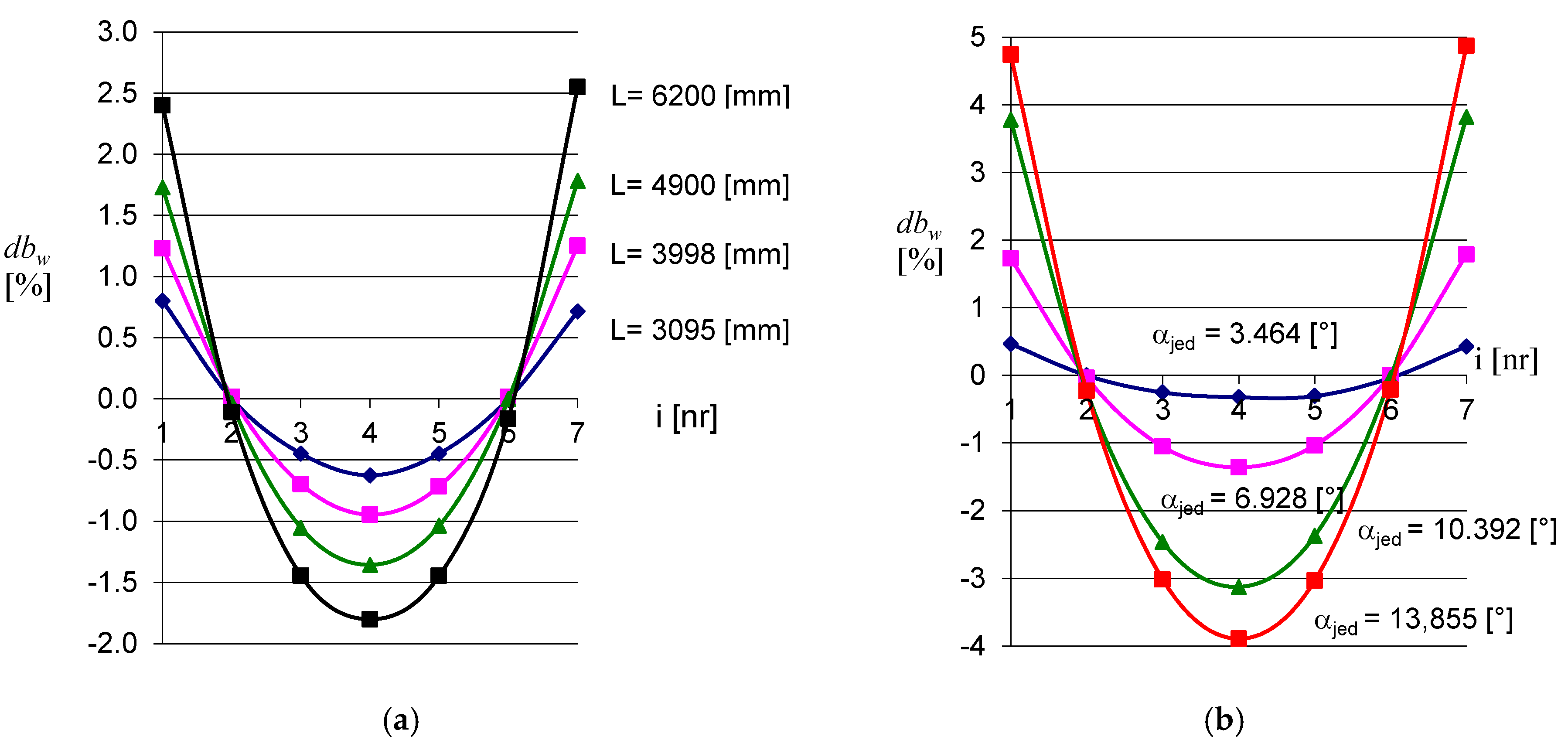
Figure 10a illustrates four experimental sheets of the same profile and different lengths. After effective shape transformations, inducing identical measure of a unit twist angle, these sheets differ in the size of the relative width increments of their folds. However, for each sheet, these increases are symmetric relative to the center measuring lines (i = 4) and the central longitudinal axis y. Figure 10b concerns four different shell forms of the same sheet of length L = 4900 mm, corresponding to four different degrees of its twist, resulting from four different values of the unit twist angle. The smallest degree of the effectively twisted sheet corresponds to the unit twist angle equal to 3.464° and leads to a form of this sheet characterized by the smallest Gaussian curvature. This figure shows that each of the achieved four corrugated shell shapes of this sheet is symmetric toward the straight line being normal to the middle surface of the sheet and passing through the central point of this surface.
For the investigated effective shape transformations, diversified shapes of directrices, including straight or curved and flat or spatial ones, can be assumed. The simplest shape of a transformed shell can be obtained as a result of supporting a corrugated strip with two skew straight lines. On the basis of the above experimental research and properties of ruled surfaces [10], the authors assumed that a central sector of a hyperbolic paraboloid can be used for modeling some effectively transformed corrugated shells. If the directrices and the transformed shell have an identical twist axis of symmetry perpendicular to these directrices, then the smooth shell model can be adopted as a central sector of a right hyperbolic paraboloid.
Therefore, the authors have proposed some methods for shaping the transformed corrugated shells by means of smooth regular warped surfaces [22,23,27]. Two of these methods are discussed in the present paper. Both methods employ the effective fold’s transformations resulting in the contraction of each designed shell appearing at a half-length of its all folds.
The first method relies on the assumption that the shape of the contracting line of the surface modeling the designed shell roof has to be adopted and the shape and position of roof directrices is calculated. A finite number of rulings arranged on the investigated warped surface compatible with the strictly defined relationships between the longitudinal straight edges of the subsequent folds of the transformed shell has to be determined. Two points lying at each ruling at distances equal to a half of the fold’s length are determined in both opposite directions from the line of contraction. Such constructed points define two transverse boundary lines of the model representing the designed transformed shell. All the selected rulings define a smooth shell model. The positions of these rulings calculated by means of the condition that the surface area of each strip limited by two adjacent rulings and modeling a single shell fold must be equal to the surface area of the rectangle modeling the fold before the transformation. Thus, if we know the parametric equation of the examined warped surface:
then we can calculate the surface area Pwpi of its selected central section limited by its two rulings as follows [9]:
where we must calculate the following Jacobi functions:
x = φ(u, v), y = ψ(u, v), z = χ(u, v)
- AA = , BB = , CC =
and ukp = −upp is half of the fold’s length, vpp = 0.0, and vkp = f(v) is the function describing the position of the edge ruling on the hyperbolic paraboloid.
The presented second method consists of adopting two roof directices, searching for a finite number of rulings modeling the longitudinal edges of the subsequent folds in the designed transformed roof shell and determining the smooth surface model of the shell.
5. Method for Geometrical Shaping Transformed Folded Shells Based on Lines of Striction
A coherent method for geometrical shaping transformed corrugated shells was developed by the authors based on specific properties of regular warped surfaces. They employed the following general vector equation of warped surface ω:
where r(u, v) = [x(u, v), y(u, v), z(u, v)] is the vector of the position of any point on a ruled surface ω, e(u) is the vector of the position of any point on directrix e intersecting all rulings ti of ω (Figure 11), and p(u) is the unit director vector of ruling ti. All vectors p(u) have a common origin at point OL that determines the spherical indicatrix p contained in sphere f of the unit radius and center OL, and u, v are two independent variables that are well-known to be curvilinear coordinates of ω.
r(u, v) = e(u) + p(u)∙v
Location of any point on a line of striction s(u) of a warped surface ω in relation to directrix e(u) of ω, can be determined by the formula:
where s(u), also called a line of contraction, is a line composed of the central points of all rulings ti of ω, and v is the parameter describing the position of any point of s(u) on respective ruling ti in relation to directrix e(u). Therefore, if the line s(u) is to be the directrix e(u), the following condition must be satisfied:
Therefore, the straight line s′(u) tangent to s(u) and the straight line p′(u) tangent to the spherical indicatrix p(u) of ω have to be perpendicular to each other:
If Equation (14) is preserved, the vector equation of the surface ω can be written as:
In the previous section, the possibilities of creating smooth models for the transformed folded shells by means of sectors of various warped surfaces were presented. One type of these surfaces is hyperbolic paraboloids (Figure 12), whose mathematical equation is as follows:
where a is a constant used to determine parabola p1 and b is a constant used to determine parabola p2.
A parametric equation of a hyperbolic paraboloid can be obtained by means of Equation (3) and the following parametric equations of its line of striction:
as well as the following parametric components of the director vector of any ruling of this paraboloid:
where the line of contraction is the sum of two parabolas contained in the planes whose equations are given as:
One of these parabolas is adopted as the line s1 of the contraction of Ω.
Another generally known type of surface used by the authors for modeling the transformed folded shells is helicoid, whose line of contraction s is helix with a constant spiral lead and constant curvature (Figure 13 and Figure 14). In the case of the investigated type of helicoid, the creation of one model Ωj of a single fold is enough to build the whole shell roof because all its folds are identically transformed. A parametric equation of this surface can be given as:
where Ro is the radius, bs is a coefficient referring to the spiral lead, and u is the selected parameter of the helix of striction of the helicoid. The helix s of contraction and ruling tj of the examined helicoid are shown in Figure 13. The ruling tj is a binormal of the line s, i.e., it is perpendicular to the osculating plane of s.
Three adjacent rulings tj−1, tj and tj+1 of the considered helicoid w, modeling the longitudinal edges of two adjacent shell folds Ωj and Ωj+1, are shown in Figure 14. The position of these rulings on the surface ω can be found from the condition that the surface area of each Ωj segment must be equal to the surface area of a rectangle modeling the respective shell fold before the transformation. The method of shaping the transformed shells using the lines of striction of warped surfaces will be presented in detail in one of the authors’ subsequent publications using a specific exemplary architectural free form roofed with a transformed roof shell.
In order to model an entire building free form roofed with a transformed folded shell, the authors use the so-called reference tetrahedrons Γ of various types. The reference tetrahedron presented in Figure 15 has four triangular walls and four vertices H1 to H4. The axis of symmetry adopted for the reference tetrahedron is also taken as the axis of symmetry of the transformed roof shell. The way of creating axis-symmetric entire free forms roofed with transformed corrugated shells is presented in the next section by a detailed example based on two border plane directrices of a transformed roof shell.
6. Method for Geometrical Shaping Transformed Folded Shells Based on Border Directrices
In the example presented in this section, an innovative authors’ method of creating free forms of entire buildings roofed with transformed corrugated shells is presented in a brief way. The second innovative method for creating the transformed corrugated shell roofs is employed here. It is based on the adoption of two edge roof directrices and its algorithm is described in detail in the further part of this section.
The mutual inclination of two skew directrices causes the inclination of all sections of the roof eaves to a horizontal plane and the diversified inclination of subsequent shell folds to this plane. To model a general free form of a building, the authors proposed using the so-called innovative reference tetrahedrons [2,14]. A common type of such a tetrahedron Γ [21] is used in the example presented below (Figure 16).
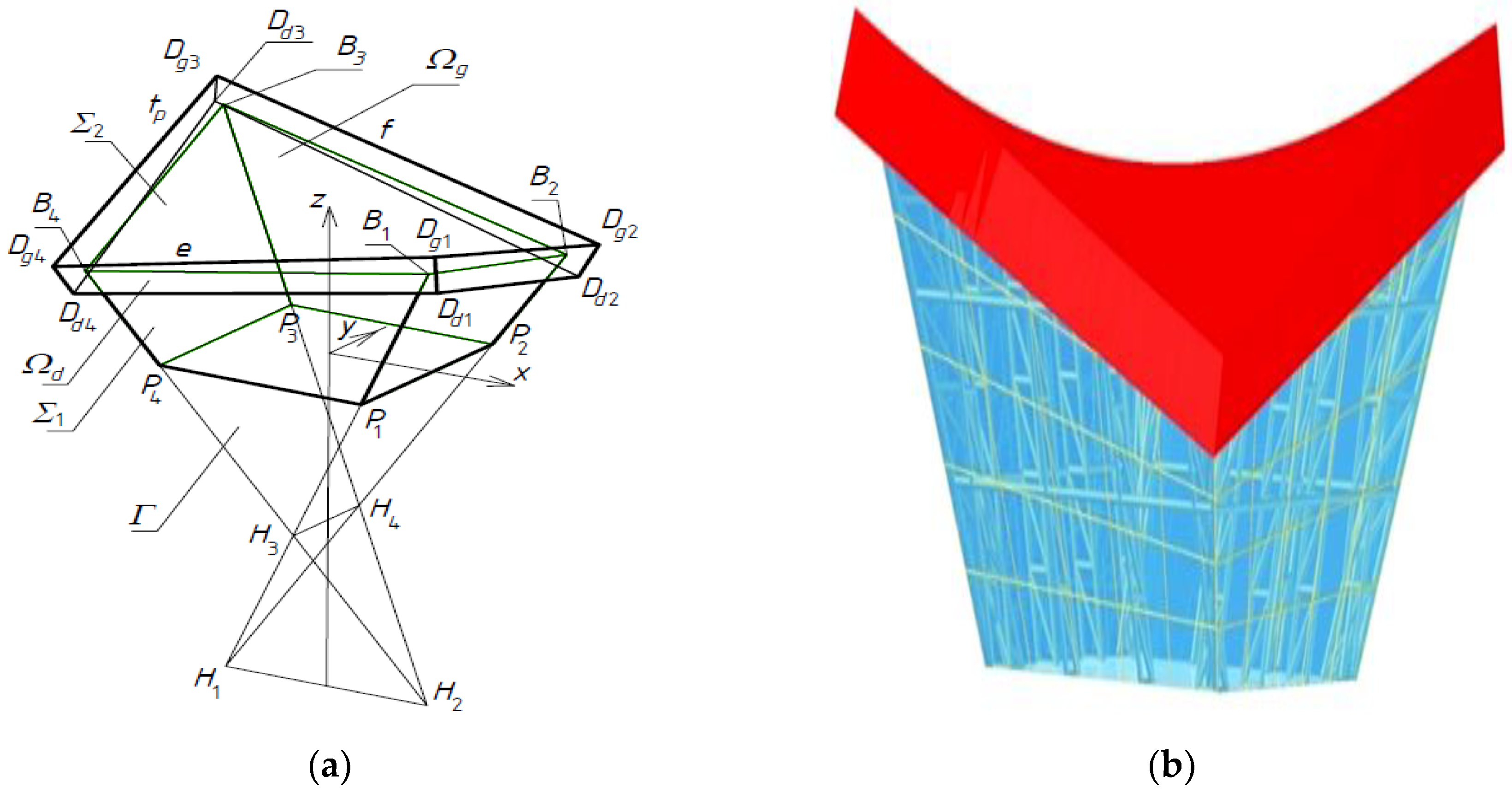
The presented free form Σ is a sum of: (a) a tetrahedral spatial shape Σ1 limited by a horizontal base plane, and (b) a roof form Σ2 bounded by two shells: upper Ωg and lower Ωd. The coordinates of the characteristic vertices of Σ are given in Table 1. A visualization of Σ is shown in Figure 16.
Two straight directrices e and f were determined on the basis of their four adopted ending points Dgi (for i = 1 to 4), whose coordinates are the entered initial data. Segments ei and fi of directrices e and f, shown in Figure 17, are the determined auxiliary short lines modeling the supporting lines of subsequent folds of the shell roof being sought. The lengths of these segments were calculated to develop the simplified smooth shell model of each roof shell fold as a central sector Ωi of a warped surface limited by two rulings ti−1 and ti. Each pair of these segments ei and fi was determined on the basis of two points Ei and Fi displaced on e and f.
The positions of points Ei on e and Fi on f were changed in relation to points Ei−1 and Fi−1, and the shape of ΩI was decided. This change makes it possible to satisfy the two conditions discussed in the concept of the paper, and relate them to the surface areas of simplified models of transformed folds and the optimal position of a contraction line along the length of each fold.
Both aforementioned conditions are represented in the authors’ application of the Rhino/Grasshopper program by two green containers shown in Figure 18. The green container on the left is related to the equality of the surface areas of the fold’s models before and after transformation. The second green container on the right requires that the contraction line pass transversely in relation to the directions of the shell folds through the middle of these folds along their lengths. This container controls the position of the contraction line s, so that it is perpendicular to the rulings ti−1 and ti.
The discussed roof shell is limited from the top and bottom by two oblique surfaces Ωg and Ωd (see Figure 16). The upper one of which is the sought-after symmetrical model of the transformed folded shell sheeting. Half of this model is presented in Figure 19. It was determined using the innovative application built by one of the authors in the Rhino/Grasshopper program.
The calculated values of the lengths of two supporting lines ei and fi, the lengths and unit twist angles αj of the consequent folds of the investigated shell, are tabulated in Table 2. The properties of the other symmetrical part can be obtained by using the z-axis symmetry of the set of the two directrices e and f.
In the example presented above, two symmetric parts are separated by an empty longitudinal strip whose width along each directrix is 70 mm. This empty strip between two symmetric parts of the roof shell should be filled with an unfolded smooth steel sheet. To obtain a continuous roof shell without the empty strip located centrally in the roof, a central longitudinal axis of this empty strip should be found. Consequently, the calculations should start taking this axis as the initial ruling of the designated shell.
Next, the longitudinal strips modeling subsequent folds passing from the central ruling of the roof shell in the direction of the eaves that are outside the roof should be determined. In this way, a smooth model of one of the two symmetric parts of the roof shell is obtained. This time, however, the empty strip, of about half the width of the aforementioned central empty strip, appears between the border fold of the modeled corrugated shell and the assumed straight line of the roof eaves. In the discussed example, the width of the border empty strip is about 35 mm.
7. Discussion
The presented symmetric geometric and mechanical properties of folded orthotropic steel sheets allow the use of symmetry in shaping attractive transformed folded roof shells and entire free forms of buildings by adopting appropriate assumptions regarding the symmetry of shape and mutual position of roof directrices as well as the position of the sheets relative to these directrices. These operations include obtaining rational pre-stresses caused by these shape transformations.
The authors have perceived the need to use various kinds of symmetry by the method in many issues they have come across in their research related to geometric, architectural and static-strength shaping of buildings characterized by unconventional architectural free forms and their warped folded shell roofs. From the authors’ experimental tests [9] and computer simulations [21] it follows that it is justified to model these transformed shells with regular ruled surfaces. In addition, since the mutual displacements of adjacent shell folds in their longitudinal directions are smaller than the displacements in transverse directions many times, the modeling should be carried out by means of warped surfaces, i.e., undeveloped ruled ones.
The visual attractiveness of the designed transformed roof shells and entire free form buildings is one of the most important advantages of exploiting symmetry. The rationality and effectiveness of the shape transformations of corrugated sheeting and the structural systems intended for free form buildings are equally important.
The simplest operation leading to obtain a transformed roof shell is based on the adoption of two directrices as a set of mutually skew straight lines, and then unfolding a continuous strip of folded sheets on these directrices. If the mutual position and shape of the directrices is adopted so that there exists an axis of symmetry of the set of these two directrices, the strip of many rectangular sheets symmetrically distributed on these directrices allows one to obtain a symmetric form of the transformed shell. Thus, the width of each fold of the effectively transformed shell decreases to a minimum at its half-length and extends maximally and identically at its both transverse ends. The maximum compressive forces appearing halfway along the length of each fold result in a contraction in this place. The sum of the contractions of all shell folds is the contraction of the entire transformed roof shell, and divides the shell into two symmetric parts.
Other important advantages of the method are as follows: simplicity, transparency and intuitiveness of creating simplified geometric models for the transformed roof shells and entire building free forms, usefulness for engineering developments. The parametrical shaping of building free forms investigated by the authors was considerably simplified by using symmetry, reducing the number of independent variables, making the method very intuitive, and carrying out parametric computer applications written in the AutoLISP language of programming an AutoCAD visual editor and a Rhino/Grasshopper program.
Two methods for shaping such transformed corrugated shells by means of smooth regular warped surfaces are discussed in the paper. These methods employ fold’s effective transformations resulting in the contraction of each designed shell appearing at a half-length of all its folds.
One method lies in the assumption that the shape of the contracting line of the surface modeling the designed shell roof has to be adopted. The roof shell directrices are sought. A finite number of rulings arranged on the investigated warped surface compatibly with strictly defined relationships between the longitudinal straight edges of the consequent folds of the transformed shell have to be determined.
Each right hyperbolic paraboloid is characterized by exactly two straight lines perpendicular to each other and belonging to two different families of rulings of this paraboloid. One of these straight lines is usually accepted as a model for the straight contraction of the shell, while the other is the twist axis and central ruling of the shell. In other cases, i.e., when such two straight lines do not exist, the shell is modeled with an oblique hyperbolic paraboloid whose contracting line is a parabola, and rulings are straight lines variously inclined to this contracting parabola.
Another particular and relatively simple form of a transformed shell is obtained by an oblique arrangement of the folds of the sheeting in relation to two circle arc directrices contained in two mutually parallel planes. In this case, the transformed shell and its contraction are modeled with a central sector and the circle neck of the revolved hyperboloid respectively, if the inclination of all shell folds to these arc directrices is identical. When the designed folded sheeting takes the form of a revolved hyperboloid, the transverse ends of its folds must be obliquely cut in order to adjust these ends to the direction of the directrices.
Another type of warped surfaces employed for modeling the transformed corrugated shells are helicoids, whose line of striction is a helix and rulings are binomial lines of the helix. The correctness of the selection of this type of warped surface for modeling the transformed shells is also justified by the fact that the plane cross-sections of all transformed folds are arranged in accordance with the contraction of the transformed shell, perpendicularly to the longitudinal axes of the shell folds if the transformation of this shell is effective. Thus, for this case the shape transformation causes no high initial stresses since the folds must retain the ability to carry roof live loads.
The advantage of this method is a relatively simple algorithm of operations and geometric models leading to the determination of a finite number of rulings located on the determined surface. The disadvantage is that the obtained transverse edge lines of the shell model are not planar lines, and the projection of the designed roof shell onto a horizontal plane is not a rectangle or square. In addition, the equation of each surface employed and its line of striction, or the way of rough approximation of the surface by means of a polyhedron and its line of contraction by means of a multi-segment line, must be known. In addition, we do not know, except for some rare cases of the surfaces verified by the authors [10], whether the accepted surface provides the appropriate positions of all its selected rulings along the line of contraction.
Another type of warped surfaces employed for modeling transformed corrugated shells are helicoids, whose line of striction is a helix and rulings are binomial lines of the helix. The correctness of the selection of this type of warped surfaces for modeling transformed shells is also justified by the fact that the plane cross-sections of all transformed folds are arranged in accordance with the contraction of the transformed shell, perpendicularly to the longitudinal axes of the shell folds if the transformation of this shell is effective. Therefore, for this case the shape transformation does not cause high initial stresses since the folds must retain the ability to carry live roof loads.
The authors find preferable the other proposed method of determining smooth models of transformed corrugated shells. It consists in taking account of two roof directices as transverse plane boundary lines of the determined smooth surface model and searching for a finite number of rulings modeling the longitudinal edges of the subsequent folds in the designed shell. Two main conditions have to be satisfied when searching for the smooth model of each shell fold [16]. The first condition requires the contraction of each shell fold to appear halfway along its length. The other condition is identical as the one of the first method and consists in maintaining the equality of surface areas of two models created for the same fold before and after transformation. An architectural stadium of two building free forms roofed with various transformed shells determined on the basis of straight and curved directrices achieved by the authors with the help of this method is presented in Figure 20.
8. Conclusions
The authors’ observations made so far on the basis of their experimental tests and computer analyses show that the main geometric feature of each effectively transformed fold is its tendency to obtain an axis-symmetric shape so that the resulting contraction divides the fold into two congruent parts. The specific kinds of regular ruled surfaces discussed in the paper allow the most extensive possible use of the geometric properties of effectively transformed folds. In particular, these surfaces should be of constant curvature and constant spiral lead of its line of contraction and rulings being binormal lines of the line of contraction. Axis-symmetric central sectors of these surfaces should be selected as the correct models for the effectively transformed roof shells discussed. In addition, these sectors must be divided by the lines of contraction into two congruent parts. Such a ruled surface is usually an open helicoid whose line of striction is a helix.
The aforementioned helix can be deformed into a straight line of striction of a right hyperbolic paraboloid of one sheet. It is also possible to position the shell folds obliquely in relation to the contraction line. For this case, the axis-symmetric smooth surface is the central sector of the revolved hyperboloid of one sheet. The neck circle is the line of contraction of the hyperboloid. The oblique position of the shell folds relative to the contraction line and directrices, resulting from the adaptation of the sheets to the shape of the revolved hyperboloid, requires an oblique cut of both transverse ends of each shell fold of the designed roof shell to obtain a smooth transverse roof shell’s edge compatibly with the direction of the roof directrices.
Various kinds of ruled surfaces can also be used as models for symmetric transformed shells, whose lines of contraction have different curvature and rulings have different inclination to the contraction and directrices. One type of these surfaces is an oblique hyperbolic paraboloid employed by the authors due to its well-known and convenient geometric properties. However, the use of this type of surface for strictly engineering developments still requires a wide range of experimental tests and computer analyses.
The other method is presented on a specific example of geometric shaping of the axis-symmetric roof shell, so that the axis is also adopted as an axis of symmetry of the designed entire building free form. Obtaining the symmetric form of a transformed roof shell requires the adoption of a symmetric set of two skew directrices and supplementing this set with a designated ruling modeling one of two longitudinal edges of any fold of the shell, for example the border fold of the shell. On the basis of the above set, a finite number of pairs of skew straight lines modeling two longitudinal straight edges of subsequent folds of the designed shell are sought. The appropriate width of each warped surface’s strip modeling a single fold of the shell is calculated based on two conditions related to the location of its contracting line and the surface area of the fold model before and after its shape transformation. All smooth models of the fold created by means of the second method are defined in a simplified and approximate way. Therefore, it is not possible to derive the mathematical equations of such shaped transformed shells.
Author Contributions
J.A. carried out research and analyses, visualized and interpreted the results, created models and method as well as wrote all sections of the paper. J.A. was the supervisor and the project administrator. A.P. participated in the concept and interpretation of the results as well as funding acquisition.
Funding
Resources were provided by the Rzeszow University of Technology.
Conflicts of Interest
The authors declare no conflicts of interest. The funders had no role in the design of the study; in the collection, analyses, or interpretation of data; in the writing of the manuscript, or in the decision to publish the results.
References
- Foraboschi, P. The central role played by structural design in enabling the construction of buildings that advanced and revolutionized architecture. Constr. Build. Mater. 2016, 114, 956–976. [Google Scholar] [CrossRef]
- Foraboschi, P. Structural layout that takes full advantage of the capabilities and opportunities afforded by two-way RC floors, coupled with the selection of the best technique, to avoid serviceability failures. Eng. Fail. Anal. 2016, 70, 377–418. [Google Scholar] [CrossRef]
- Abel, J.F.; Mungan, I. Fifty Years of Progress for Shell and Spatial Structures; International Association for Shell and Spatial Structures Publishing: Madrid, Spain, 2011. [Google Scholar]
- Medwadowski, S.J. Symposium on Shell and Spatial Structures: The Development of Form. Bull. IASS 1979, 70, 3–10. [Google Scholar]
- Saitoh, M. Recent Spatial Structures in Japan; J. JASS: Madrid, Spain, 2001. [Google Scholar]
- Foraboschi, P. Optimal design of glass plates loaded transversally. Mater. Des. 2014, 62, 443–458. [Google Scholar] [CrossRef]
- Liu, Y.; Zwingmann, B. Carbon Fiber Reinforced Polymer for Cable Structures—A Review. Polymers 2015, 7, 2078–2099. [Google Scholar] [CrossRef]
- Makowski, Z.S. Analysis, Design and Construction of Double-Layer Grids; Applied Science Publishers: London, UK, 1981. [Google Scholar]
- Abramczyk, J. Influence of the Shape of Flat Folded Sheets and Curved Directrices on the Geometrical Forms of Transformed Shells; Rzeszow University of Technology: Rzeszów, Poland, 2011. (In Polish) [Google Scholar]
- Abramczyk, J. Shell Free Forms of Buildings Roofed with Transformed Corrugated Sheeting; Rzeszow University of Technology: Rzeszów, Poland, 2017. [Google Scholar]
- Obrębski, J.B. Observations on Rational Designing of Space Structures. In Proceedings of the Symposium Montpellier Shell and Spatial Structures for Models to Realization IASS, Montpellier, France, 20–24 September 2004; pp. 24–25. [Google Scholar]
- Rębielak, J. Review of Some Structural Systems Developed Recently by help of Application of Numerical Models. In Proceedings of the XVIII International Conference on Lightweight Structures in Civil Engineering, Łódź, Poland, 7 December 2012; pp. 59–64. [Google Scholar]
- Reichhart, A. Geometrical and Structural Shaping Building Shells Made up of Transformed Flat Folded Sheets; Rzeszow University of Technology: Rzeszów, Poland, 2002. (In Polish) [Google Scholar]
- Grey, A. Modern Differential Geometry of Curves and Surfaces with Mathematica, 4th ed.; Champman & Hall: New York, NY, USA, 2006. [Google Scholar]
- Abramczyk, J. Principles of geometrical shaping effective shell structures forms. JCEEA 2014, XXXI, 5–21. [Google Scholar] [CrossRef]
- McDermott, J.F. Single layer corrugated steel sheet hypars. Proc. ASCE J. Struct. Div. 1968, 94, 1279–1294. [Google Scholar]
- Egger, H.; Fischer, M.; Resinger, F. Hyperschale aus Profilblechen. Stahlbau 1971, 12, 353–361. [Google Scholar]
- Gergely, P.; Banavalkar, P.V.; Parker, J.E. The analysis and behavior of thin-steel hyperbolic paraboloid shells. In Review in A Research Project Sponsored by the America Iron and Steel Institute; Report 338; Ithaca: New York, NY, USA, 1971. [Google Scholar]
- Davis, J.M.; Bryan, E.R. Manual of Stressed Skin Diaphragm Design; London: Granada, Spain; London, UK, 1982. [Google Scholar]
- Petcu, V.; Gioncu, D. Corrugated hypar structures. In Proceedings of the I International Conference on Lightweight Structures in Civil Engineering, Warsaw, Poland, 1 December 1995; pp. 637–644. [Google Scholar]
- Abramczyk, J. Shape transformations of folded sheets providing shell free forms for roofing. In Proceedings of the 11th Conference on Shell Structures Theory and Applications, Gdańsk, Poland, 11–13 October 2017; Pietraszkiewicz, W., Witkowski, W., Eds.; CRC Press Taylor and Francis Group: Boca Raton, FL, USA, 2017; pp. 409–412. [Google Scholar]
- Abramczyk, J. Transformed Shell Roof Structures as the Main Determinant in Creative Shaping Building Free Forms Sensitive to Man-Made and Natural Environments. Buildings 2019, 9, 74. [Google Scholar] [CrossRef] [Green Version]
- Prokopska, A.; Abramczyk, J. Parametric Creative Design of Building Free Forms Roofed with Transformed Shells Introducing Architect’s and Civil Engineer’s Responsible Artistic Concepts. Buildings 2019, 9, 58. [Google Scholar]
- Kidmann, R.; Kraus, M. Steel Structures. Design Using FEM; Ernst & Sohn: Berlin, Germany, 2011. [Google Scholar]
- Cook, R.D.; Malkus, D.S.; Plesha, M.E.; Witt, R.J. Concepts and Applications of Finite Element Analysis. Design Using FEM; John Wiley & Sons Inc.: New York, NY, USA, 2002. [Google Scholar]
- Bathe, K.J. Finite Element Procedures in Engineering Analysis; Prentice-Hall Inc.: Englewood Cliffs, NJ, USA, 1982. [Google Scholar]
- Abramczyk, J.; Prokopska, A. Responsive Parametric Building Free Forms Determined by Their Elastically Transformed Steel Shell Roofs Sheeting. Buildings 2019, 9, 4. [Google Scholar]
Figure 1.
Two asymmetric experimental corrugated shells supported by: (a) curvilinear; (b) straight skew directrices.
Figure 1.
Two asymmetric experimental corrugated shells supported by: (a) curvilinear; (b) straight skew directrices.

Figure 2.
Symmetric roof shells of two structures of: (a) shopping stories; (b) a silo.

Figure 3.
Two symmetrical experimental hyperbolic paraboloid shells: (a) with stiffen edges; (b) without stiffen edges.
Figure 3.
Two symmetrical experimental hyperbolic paraboloid shells: (a) with stiffen edges; (b) without stiffen edges.

Figure 4.
Symmetrically arranged hyperbolic paraboloid shell units: (a) an erected corrugated shed; (b) geometrical smooth models.
Figure 4.
Symmetrically arranged hyperbolic paraboloid shell units: (a) an erected corrugated shed; (b) geometrical smooth models.

Figure 5.
Folded mechanical thin-walled model of nominally plane folded sheet transformed elastically and initially into a shell shape and the graphical expression of the “effective” stresses in MPa on its top surface. (a) The direction of the view according to the longitudinal axis of the edge fold. (b) The direction of the view skew to the longitudinal axis of any fold. (c) An initially transformed and uniformly loaded sheeting.

Figure 6.
Linear dependence between the normal stresses σyy = σy acting perpendicularly to the longitudinal axes of shell folds and the corresponding strains εyy = εy of an effectively transformed thin-walled corrugated shell.
Figure 6.
Linear dependence between the normal stresses σyy = σy acting perpendicularly to the longitudinal axes of shell folds and the corresponding strains εyy = εy of an effectively transformed thin-walled corrugated shell.

Figure 7.
Symmetrical character of the relative width increments dbw of three folds (n = 1 to 3) of the same sheet measured as compatible with seven (i = 1 to 7) measuring lines passing perpendicularly to the longitudinal fold’s axes in relation to the longitudinal axes of all folds of the length L = 4900 [mm] and the unit twist angle αjed = 6928 [o]. (a) The width increments presented along transverse measuring lines. (b) The width increments presented along longitudinal axes of these folds.

Figure 8.
Measuring lines and points traced on the top surface of a rectangular experimental sheet.

Figure 9.
Scheme of the arrangement of measuring points Pi, j, α located at the intersection of longitudinal lines (n = 1 to 3) separating single folds and transverse measuring lines (i = 1 to 7) on a rectangular folded sheet.
Figure 9.
Scheme of the arrangement of measuring points Pi, j, α located at the intersection of longitudinal lines (n = 1 to 3) separating single folds and transverse measuring lines (i = 1 to 7) on a rectangular folded sheet.

Figure 10.
Symmetrical character of the relative width increments dbw of shell folds along seven (i = 1 to 7) measuring lines passing perpendicularly to the longitudinal fold’s axes obtained for: (a) four various sheets twisted by the same unit angle αjed = 6928 [o] and characterized by various lengths; (b) the same sheet of length L = 4900 [mm] and twisted by various unit angles.

Figure 11.
A central sector Ω determined on the basis of the line of striction s and spherical indicatrix p of a warped surface.
Figure 11.
A central sector Ω determined on the basis of the line of striction s and spherical indicatrix p of a warped surface.

Figure 12.
Z-axis-symmetrical sector Ω of oblique (a differs from b) hyperbolic paraboloid ω adopted as a model for a corrugated transformed shell.
Figure 12.
Z-axis-symmetrical sector Ω of oblique (a differs from b) hyperbolic paraboloid ω adopted as a model for a corrugated transformed shell.

Figure 13.
Line of contraction s and binormal ti of the respective Frenet’s frame (sj, nj, tj) of s used as a ruling of the designed helicoid.
Figure 13.
Line of contraction s and binormal ti of the respective Frenet’s frame (sj, nj, tj) of s used as a ruling of the designed helicoid.

Figure 14.
Geometrical shaping of consequent folds of a transformed corrugated shell with sectors Ωj limited by pairs of skew rulings tj−1 and tj distinguished on a helicoid.
Figure 14.
Geometrical shaping of consequent folds of a transformed corrugated shell with sectors Ωj limited by pairs of skew rulings tj−1 and tj distinguished on a helicoid.

Figure 15.
Shaping of an axial-symmetric unconventional building free form by means of a reference tetrahedron Γ.
Figure 15.
Shaping of an axial-symmetric unconventional building free form by means of a reference tetrahedron Γ.

Figure 16.
(a) Simplified model Σ = Σ1 ∪ Σ2 of the discussed building free forms taking account of the thickness and overhang of the transformed shell roof Σ2 and the spatial shape Σ1 limited by elevation walls. (b) Visualization of the examined building free form Σ.
Figure 16.
(a) Simplified model Σ = Σ1 ∪ Σ2 of the discussed building free forms taking account of the thickness and overhang of the transformed shell roof Σ2 and the spatial shape Σ1 limited by elevation walls. (b) Visualization of the examined building free form Σ.

Figure 17.
Narrow smooth longitudinal shell strip Ωi modeling a complete shell fold, created by means of a Loft component and limited by two rulings ti−1(Ei−1, Fi−1) and ti (Ei, Fi) as well as two curves ei and fi.
Figure 17.
Narrow smooth longitudinal shell strip Ωi modeling a complete shell fold, created by means of a Loft component and limited by two rulings ti−1(Ei−1, Fi−1) and ti (Ei, Fi) as well as two curves ei and fi.

Figure 18.
Two basic green components representing two basic conditions related to the fold’s surface areas and line of contraction.
Figure 18.
Two basic green components representing two basic conditions related to the fold’s surface areas and line of contraction.

Figure 19.
Smooth model of the upper surface of the shell roof being sought.

Figure 20.
The architectural stadium of two free form buildings roofed with various transformed shells determined on the basis of straight and curved directrices.
Figure 20.
The architectural stadium of two free form buildings roofed with various transformed shells determined on the basis of straight and curved directrices.


Table 1.
Coordinate of the vertices of the examined free form Σ shown in Figure 16.
Table 1.
Coordinate of the vertices of the examined free form Σ shown in Figure 16.
| Vertex | X-Coordinate | Y-Coordinate | Z-Coordinate |
|---|---|---|---|
| P1 | 5000 | −5000.0 | 0 |
| P2 | 5000 | 5000 | 0 |
| P3 | −5000.0 | 5000 | 0 |
| P4 | −5000.0 | −5000.0 | 0 |
| B1 | 10,000.00 | −7500.0 | 10,000.00 |
| B2 | 7777.7 | 6388.9 | 5555.6 |
| B3 | −10,000.0 | 7500 | 10,000.00 |
| B4 | −7777.7 | −6388.9 | 5555.6 |
| Dg1 | 10,650.60 | −8016.9 | 11,382.60 |
| Dg2 | 8697 | 7448.5 | 5996.4 |
| Dg3 | −10,650.6 | 8016.9 | 11,382.60 |
| Dg4 | −8697.0 | −7448.5 | 5996.4 |
| Dd1 | 11,129.50 | −8585.8 | 9526 |
| Dd2 | 8156.6 | 6739.5 | 4206.1 |
| Dd3 | −11,129.5 | 8585.8 | 9526 |
| Dd4 | −8156.6 | −6739.5 | 4206.1 |
| H1 | −5000 | 0 | −20,000.0 |
| H2 | 5000 | 0 | −20,000.0 |
| H3 | 0 | −2500.0 | −10,000.0 |
| H4 | 0 | 2500 | −10,000.0 |
Values in millimeters. In order to increase the attractiveness and integrity of an entire building free form consisting of a spatial roof shape and a spatial shape limited by facade walls, the facade walls [5,6] have been appropriately inclined to the vertical. The z-axis of the global coordinate system [x, y, z] (see Figure 16a) is also an axis of Γ. The Ωg surface was modeled in the Rhino/Grasshopper program in the following way. The directrices e and f of Ωg were adopted in the form of straight sections having ends in points Dgi (i = 1 to 4) at the beginning of the calculations. The straight line (Dg3, Dg4) was adopted as an initial ruling tp of Ωg. Selected rulings ti of the surface Ωg modeling the longitudinal edges of the subsequent folds of this shell are sought. The distance between two adjacent rulings tj−1 and tj, which are the longitudinal edges of the same smooth strip modeling a single shell roof fold, was determined on the basis of two conditions related to the contraction of each transformed shell fold and the equality of the surface areas of two smooth models of this fold before and after transformation.
Table 2.
Parameters describing the subsequent shell folds in the transformed shell whose simplified smooth model is shown in Figure 19.
Table 2.
Parameters describing the subsequent shell folds in the transformed shell whose simplified smooth model is shown in Figure 19.
| Shell Fold [no.] | Length of Supporting Line ei [mm] | Length of Supporting Line fi [mm] | Fold’s Length [mm] | Fold’s Unit Twist Angle αj [o] |
|---|---|---|---|---|
| 1 | 286.8 | 294.1 | 16,467 | 1.809 |
| 2 | 286.9 | 294 | 16,416 | 1.8199 |
| 3 | 287 | 293.8 | 16,367 | 1.8306 |
| 4 | 286.4 | 293.1 | 16,319 | 1.8411 |
| 5 | 287.1 | 293.6 | 16,273 | 1.8514 |
| 6 | 287.2 | 293.5 | 16,227 | 1.8614 |
| 7 | 287.3 | 293.4 | 16,184 | 1.8713 |
| 8 | 287.4 | 293.2 | 16,142 | 1.8808 |
| 9 | 287.5 | 293.1 | 16,101 | 1.8902 |
| 10 | 287.5 | 293 | 16,061 | 1.8992 |
| 11 | 287.6 | 292.9 | 16,024 | 1.908 |
| 12 | 287.7 | 292.7 | 15,988 | 1.9165 |
| 13 | 287.8 | 292.6 | 15,953 | 1.9247 |
| 14 | 287.9 | 292.5 | 15,919 | 1.9326 |
| 15 | 288 | 292.4 | 15,887 | 1.9403 |
| 16 | 288.1 | 292.3 | 15,857 | 1.9476 |
| 17 | 288.2 | 292.1 | 15,828 | 1.9545 |
| 18 | 288.3 | 292 | 15,800 | 1.9612 |
| 19 | 288.3 | 291.8 | 15,774 | 1.9675 |
| 20 | 288.4 | 291.8 | 15,750 | 1.9735 |
| 21 | 288.6 | 291.6 | 15,727 | 1.9791 |
| 22 | 288.6 | 291.5 | 15,705 | 1.9843 |
| 23 | 288.7 | 291.4 | 15,685 | 1.9892 |
| 24 | 288.8 | 291.3 | 15,667 | 1.9938 |
| 25 | 288.9 | 291.2 | 15,650 | 1.998 |
| 26 | 289.1 | 291.1 | 15,635 | 2.0017 |
| 27 | 289.1 | 291 | 15,622 | 2.0051 |
| 28 | 289.3 | 290.8 | 15,610 | 2.0081 |
| 29 | 289.4 | 290.7 | 15,599 | 2.0108 |
| 30 | 289.5 | 290.6 | 15,590 | 2.013 |
| 31 | 289.6 | 290.5 | 15,583 | 2.0149 |
| 32 | 289.7 | 290.3 | 15,577 | 2.0163 |
| 33 | 289.8 | 290.3 | 15,573 | 2.0174 |
| 34 | 289.9 | 290.1 | 15,570 | 2.018 |
| 35 | 290 | 290 | 15,569 | 2.0183 |
© 2019 by the authors. Licensee MDPI, Basel, Switzerland. This article is an open access article distributed under the terms and conditions of the Creative Commons Attribution (CC BY) license (http://creativecommons.org/licenses/by/4.0/).
Share and Cite
MDPI and ACS Style
Abramczyk, J.; Prokopska, A. Symmetric Shape Transformations of Folded Shell Roofs Determining Creative and Rational Shaping of Building Free Forms. Symmetry 2019, 11, 1438. https://doi.org/10.3390/sym11121438
AMA Style
Abramczyk J, Prokopska A. Symmetric Shape Transformations of Folded Shell Roofs Determining Creative and Rational Shaping of Building Free Forms. Symmetry. 2019; 11(12):1438. https://doi.org/10.3390/sym11121438
Chicago/Turabian StyleAbramczyk, Jacek, and Aleksandra Prokopska. 2019. "Symmetric Shape Transformations of Folded Shell Roofs Determining Creative and Rational Shaping of Building Free Forms" Symmetry 11, no. 12: 1438. https://doi.org/10.3390/sym11121438
Note that from the first issue of 2016, this journal uses article numbers instead of page numbers. See further details here.