Spring Effects on Workspace and Stiffness of a Symmetrical Cable-Driven Hybrid Joint


1
College of Mechanical and Electrical Engineering, Zaozhuang University, Zaozhuang 277160, China
2
School of Mechanical Engineering, Hebei University of Technology, Tianjin 300130, China
*
Authors to whom correspondence should be addressed.
Symmetry 2020, 12(1), 101; https://doi.org/10.3390/sym12010101
Submission received: 25 November 2019
/
Revised: 27 December 2019
/
Accepted: 28 December 2019
/
Published: 5 January 2020
(This article belongs to the Special Issue Symmetry in Engineering Sciences II)
Abstract
:This paper aims to investigate how to determine the basic parameters of the helical compression spring which supports a symmetrical cable-driven hybrid joint (CDHJ) towards the elbow joint of wheelchair-mounted robotic manipulator. The joint design of wheelchair-mounted robotic manipulator needs to consider lightweight but robust, workspace requirements, and variable stiffness elements, so we propose a CDHJ which becomes a variable stiffness joint due the spring under bending and compression provides nonlinear stiffness characteristics. Intuitively, different springs will make the workspace and stiffness of CDHJ different, so we focus on studying the spring effects on workspace and stiffness of CDHJ for its preliminary design. The key to workspace and stiffness analysis of CDHJ is the cable tension, the key to calculate the cable tension is the lateral bending and compression spring model. The spring model is based on Castigliano’s theorem to obtain the relationship between spring force and displacement. The simulation results verify the correctness of the proposed spring model, and show that the spring, with properly chosen parameters, can increase the workspace of CDHJ whose stiffness also can be adjusted to meet the specified design requirements. Then, the modelling method can be extended to other cable-driven mechanism with a flexible compression spring.
1. Introduction
Wheelchair-mounted robotic manipulator is a typical type of the service robot which can help users with motor impairments to perform activities of daily living [1,2,3,4], such as feeding, drinking, dressing, and retrieval of daily objects. The research of wheelchair-mounted robotic manipulator has been going on for nearly 55 years [1,4]. In the past, there are nearly a dozen wheelchair-mounted robotic manipulators which have been developed. However, due to its poor usability, low payload, and high cost, it is not widely used in the market [3,4]. Specifically, for example, the manipulator is heavy, the joints are bulky, and the flexible motion is limited [5]. These problems may be solved by the cable-driven mechanism (CDM), owing to its following remarkable characteristics: small inertia, large workspace, high payload, good transportability, fully remote actuation, and ideal reconfigurability [5,6,7,8,9]. Based on these characteristics, CDM is widely applied in engineering [6]. Several applications are listed as follows. Chen et al. [10] proposed a cable-driven parallel waist rehabilitation robot; Liu et al. [11] proposed a spatial serpentine tail which used a cable-driven circular shape joint; Eftychios et al. [12] proposed a reconfigurable articulated structure considered the structural concept for reconfigurable buildings; Qiao et al. [13] presented the self-adaptive grasp process of a finger which has three degrees of freedom and under actuated cable truss.
Meanwhile, a wheelchair-mounted robotic manipulator as a collaborative robot [14] must perform compliant motion in order to realize physical human-robot interaction [15], because in the field of collaborative robotics to realize physical human-robot interaction, impact mitigation is a core issue [14]. That is to say, in the mechanical structure it needs used variable stiffness elements. So far, a number of variable stiffness elements have been developed. One of them is CDM which is considered to be antagonistic variable stiffness mechanism [16,17] inspired by the musculoskeletal system [18,19]. CDM can generate variable stiffness very effectively with large stiffness variations and it need not modify the equilibrium configuration [16]. Yeo et al. [20] proposed cable-driven manipulators with variable stiffness; Xu et al. [21] proposed a cable-driven soft robot arm in the underwater environment; Liu et al. [22] used the mechanism structure of the human arm for reference, proposed a cable-driven manipulator with a high-payload capacity, assembled physical prototype and tested the payload capacity. Besides, the spring is usually used in most of the variable stiffness designs [23,24,25]. Seriani et al. [14] investigated the preloaded structures for impact mitigation used the fundamental preloaded element, a spring; However, Wu et al. [26] proposed the linear variable-stiffness mechanisms used the preloaded element, a curved beam. López-Martínez et al. [27] proposed a passive mechanical system which consists in a flexible linkage used a preloaded compression spring. Azadi et al. [16] pointed out that changing the geometry of the system can change the stiffness, such as controlling the active coils number of a coil spring, using regulable pitching stiffness, and changing the gap between two leaf springs. Overall, CDM coupled with stiffness adjustability may address some issues of wheelchair-mounted robotic manipulator joint design with relatively low energy consumption and low cost.
As is known to all, cables must remain in tension while performing tasks. Therefore, the study of the CDM workspace must consider the cable tension. There are some different workspaces which have been identified like static equilibrium workspace, wrench-closure workspace, and wrench-feasible workspace [28,29]. Analysis of these workspace generally starts from static equilibrium equations. Static equilibrium workspace and wrench-closure workspace are essentially the same, which are the set of poses where the end-effector can physically maintain equilibrium and all cables are in tension; nevertheless, wrench-feasible workspace is defined as the set of poses where cables tension remains within a prescribed range, the range is usually from the allowable minimum cable tension value to the maximum cable tension value [28,29,30,31]. In addition, many applications require the end-effector to bear certain force/moment combinations in the workspace. Accordingly, the wrench-feasible workspace is considered as the most appropriate workspace [31], which is able to connect with the physical world, and is the most practical workspace for CDM [29]. In this paper, the mentioned workspace is wrench-feasible workspace.
CDM stiffness analysis can be divided into static stiffness analysis and dynamic stiffness analysis [32,33]. Yuan et al. [32] and Nguyen et al. [34] pointed out that analysis and improvement of the static positioning accuracy is the purpose of static stiffness analysis of CDM, especially in the pick-and-place application. In this paper, the mentioned stiffness is static stiffness. However, the vibration analysis is the purpose of dynamic stiffness analysis of CDM in those applications [32,33], requiring high performances [35], especially dynamic performances [36]. Most researchers took cables as massless springs which just considered axial stiffness of cables when CDM is with the light-weighted [34], low speed [33], and small size [37,38], and used the Jacobian-based stiffness analysis method [32,39,40,41,42] to make static stiffness analysis to describe the Cartesian stiffness matrix which is the function of the manipulator’s configuration and mechanism stiffness values. However, it needs to consider transversal stiffness when the cable profile is a sagging curve, the Jacobian-based stiffness analysis method is not applicable [32]. Amare et al. [33] made dynamic stiffness analysis of the CDM in three-dimensional inclined plane with external forces exerted by hydraulic cylinder on the system. Yuan et al. [43] solved the vibration problems of structures used dynamic stiffness matrix method which is used to identify the system natural frequencies.
Spring, as a common component, has been applied in various fields. Although the helical compression spring is commonly used to increase the performance of CDM, only a few studies attempted to systematically analyze springs effects on the workspace and stiffness of CDM. Duan et al. just analyzed the effects on the workspace of CDM with springs which are parallel to the cable, and had no detailed analysis of the effects of spring basic parameters [44]. Similarly, in [45,46], they also took spring as spring cable. Mustafa and Agrawal studied spring placement effects on altering the cable tension required and increasing the feasible workspace [45]. Taghavi et al. [46] investigated adding springs in between the links to improve the wrench-feasible workspace of a two-link CDM. Essentially Duan et al. [44], Mustafa and Agrawal [45], and Taghavi et al. [46] treat springs as passive cables in a straight line shape. During the whole CDM movement, the spring stiffness did not change. In [5,36,47,48], they proposed a CDM with a linear compression spring spine which presents the nonlinear stiffness characteristics under bending and compression, but they did not analyze the impact of adding springs on the workspace and stiffness of CDM in detail. Gao et al. [47], Zhang et al. [5], and Zhang et al. [36] treated the helical spring as a spatially curved bar. This concept of an equivalent column of helical spring is in most engineering applications in [49]. Yigit et al. analyzed helical spring using Castigliano’s Theorem [48]. The same idea is used for helical spring analysis as in [50].
This paper focuses on the spring effects on workspace and stiffness of a symmetrical cable-driven hybrid joint (CDHJ) towards the elbow joint of wheelchair-mounted robotic manipulator for its preliminary design in detail. That is to say, though the spring effects analysis, the basic parameters of the helical compression spring of CDHJ can be determined, which makes preparations for the next assembly prototype. Using Castigliano’s Theorem, which is proposed in [48,50], the helical spring is analyzed to obtain the relationship between spring force and spring displacement. On the basis the statics, the Cartesian stiffness matrix is derived by the Jacobian-based stiffness analysis method [32,39,40,41,42] to deduce static stiffness analysis index of CDHJ. Intuitively, a spring, with properly chosen parameters, can help in keeping cables taut resulting in larger workspace and adjusting CDHJ stiffness to satisfy the specified design requirements.
This paper aims to investigate how to determine the basic parameters of the helical compression spring. Used Castigliano’s theorem the relationship between spring force and displacement is obtained, which is determined by the spring configuration, the geometry, and material properties. The spring parameters are determined by the spring effects on workspace and stiffness of CDHJ. This study is a first step in the CDHJ design. Hence, this research method can guide the design of other CDM with a flexible compression spring with workspace and stiffness requirements. With relatively large workspace, smooth motion, and light structure, the proposed CDHJ might have potential use for wheelchair-mounted robotic manipulator elbow joint.
This paper is organized as follows. The concept of CDHJ and the kinematic modeling is presented in Section 2; next, the modeling of spring lateral bending and compression is given in Section 3; the workspace and stiffness index of CDHJ is given in Section 4; the springs effects on the workspace and stiffness of CDHJ are studied in Section 5; and finally, discussions obtained from the results are presented in the last section.
2. CDHJ Description and Kinematic Analysis
2.1. CDHJ Description
The muscles which control the movement of the human elbow joint are the triceps and the biceps. The elbow joint movement are the antagonistic movement. Flexion occurs when the biceps contracts and the triceps relaxes, while extension occurs when the biceps relaxes and the triceps contracts. Hence, the musculoskeletal mechanism of the human elbow joint reflects symmetry. Based on the mechanism, in order to realize the symmetry of motion, an elbow joint driven by 2 cables and supported by a compression spring in the central position has been designed for the elbow joint of the wheelchair-mounted robotic manipulator. As shown in Figure 1a, cable 1 and cable 2 drive the upper platform (moving platform), and imitate biceps brachii and triceps brachii, respectively. The two platforms are supported by a compression spring, which is the parallel part; two rigid shafts with a rotating pair are in the center of the spring, and rigid shaft 1 passes through the moving platform, forming the series part. Overall, this elbow joint is a symmetrical cable-driven hybrid joint. This symmetry is reflected not only in structure but also in motion, in other words, the upper platform motion of the spring clockwise bend as Figure 1b is the same as the spring counter clockwise bend, so in the next analysis, only the clockwise motion shown in Figure 1b will be analyzed.
Due under bending and compression linear helical compression spring provides nonlinear stiffness characteristics, the CDHJ is a variable stiffness joint. Rigid shaft 1 passes through the upper platform, therefore the CDHJ stiffness can be adjusted by translational motion of the upper platform. Due to the limitation of the intermediate rigid shaft, the CDHJ has a total of two degrees of freedom. Therefore, CDHJ is the simplification of variable stiffness mechanism. That is to say, the CDHJ with stiffness adjustability towards wheelchair-mounted robotic manipulator elbow joint may ameliorate some safety issues in the physical human-robot interaction due to its relatively low energy consumption and low cost.
2.2. Kinematic Analysis
The cables whose profile is a straight line are assumed to have negligible mass. The diagram of the CDHJ is illustrated in Figure 1b. {O1 × 1y1} is the global coordinate system, {O2x2y2} is a local coordinate frame, all the coordinate origins are at the center of the platform. The upper and lower platforms are thin round plates, their radii are b and a, respectively. Denote A1, B1, A2, and B2 as the connecting points of cables 1 and 2, respectively; and the distance from O1 to the rotating pair center as d. The spring is simplified and drawn as an arc.
As mentioned in the previous section, the CDHJ has a total of 2 degrees of freedom: the rotation around the z-axis, and the translational motion on the x-y plane. According to the right hand rule, when the bend direction is clockwise as shown in Figure 1b, θ is negative. Under the rigid restraint of the rotating pair in the center of the spring, the relationship between translational component along the x-axis and that along the y-axis in the global coordinate system can be expressed as:
Denote as the vector defining the mth cable, (m = 1,2), in the global coordinate system; is , is , in the global coordinate system; is , in the local coordinate system.
The input of CDHJ is (l1, l2), the output is (y, θ). The kinematic relationship between the input and output can be obtained used the closed loop vector method:
where .
Since m = 1,2, Equation (2) can be expanded as and . Hence, the cable lengths is , , and .
Equation (1) differentiates time, and we obtain:
The dot product of is as follows.
Equation (4) differentiates time, using , and substitute Equation (3) into it and simplify it, and we obtain:
where ; ; ; .
Hence,
where . Thus, the velocity Jacobian matrix
is obtained. It is the nonlinear mapping between the position change of the upper platform and the length change of the cable, and it is necessary for the analysis of CDHJ stiffness.
3. Modeling of Spring Lateral Bending and Compression
The spring in this CDHJ is subjected to bending and compression effects. The key to cable tension analysis and CDHJ stiffness is spring lateral bending and compression model. In most engineering applications, the coil spring under lateral buckling could be treated as an elastic beam [5,36,47,49,51]. Based this concept of an equivalent beam of helical spring, although wrenches of the spring exerted on the moving platform can be calculated, the influence of different springs on the performance of the mechanism cannot be analyzed by using this model. Therefore, in this paper, spring lateral bending and compression analysis uses the idea in [48,50] to study the effects of different spring parameters on the joint workspace and stiffness in detail. The essence of this modelling idea is to obtain the relationship between spring force and spring displacement based on Castigliano’s theorem. This modeling is developed based each coil of the spring analyzed separately, but the concept of an equivalent beam of helical spring is to simply crumple all the coils into one beam. Hence, according to this idea, the helical spring lateral bending and compression model diagram is shown in Figure 2. Figure 2a is the spring force analysis of the CDHJ. Cable forces T1 and T2 acting on the upper plate are equivalent to generalized forces F1e, F2e, and Me. The frame {Okxkykzk} is attached to the center of the helix section corresponding to the helix end point of each coil. The variable k is the index number of the active coils. Two Cartesian coordinate systems {O0x0y0z0} and {Oxyz} are fixed to the lower and upper platforms, respectively, with {O0x0y0z0} being the global coordinate system coincident on the center of helix section corresponding to helix initiation point of the first coil. The number of spring active coils is n. Each coil frame is rotated around its z-axes in equally, finally yn-axis and y-axis are tangent. In order to use Castigliano’s theorem, Figure 2b shows the infinitesimal elements defined in the helical spring as. The infinitesimal element angular position on k-th coil is defined as α on xk-zk plane. Two forces exert on each spring coil infinitesimal element. One is on tangential direction coincident on ɛz, the other is on normal direction coincident on ɛx.
The position vector is with respect to the local frame {Okxkykzk}. Obviously, . is denoted as the position of the infinitesimal element in the particular coil frame {Okxkykzk}. In the deformed configurations of the spring bend, it is desired that it is the shape of a circular arc. Meanwhile, due the platform motion is symmetric, the analysis only discusses the clockwise bend as shown in Figure 1b. Hence, θ is negative. , where , R is radius of the helical spring, and n is the active coils number.
The position vector is with respect to the global coordinate system. And , so .
The generalized forces vectors , , and are with respect to the global coordinate system. So, , , and . Then, , , and . So far, can be obtained as follows, which is the total moment acting on the infinitesimal element.
where, , which is the moment acting on the element resulting from the equivalent force vector . Similarly, .
According to the Castigliano’s theorem, it should be defined in the element specific frame {εxεyεz}. The moment vector .
The strain energy in k-th coil, due to each element of moment vector is given by
where the modulus of elasticity is E, the shear modulus is G, the moment inertia is I, the polar moment inertia is J. So, strain energy in the k-th coil is the summation of three strain energies.
The spring total strain energy is the summation of all the coil strain energies.
Castigliano’s theorem is now invoked to determine the relationship between spring force and spring displacement.
Equations (11a), (11b), and (11c) can be written in given form in Equation (12).
where D is a 3 × 3 matrix. Let Kp be D−1, then the important relationship becomes:
where . From Equation (1), , substitute it into Kp and simplify, Equation (13) can become:
where .
Equation (14) reveals the nonlinear force-deformation relation or stiffness equation of the spring. Wrenches of the spring exerted on the moving platform can be calculated by Equation (14), and then through the static analysis of the moving platform, the cable tension can be obtained. Matrix K is a more complex form of proportionality factor, which is determined by the spring configuration, the geometry and material properties and is not a constant. That is to say, the linear helical compression spring became a nonlinear stiffness spring under the bending and compression effects. So, CDHJ is a variable stiffness joint. Through translational motion, the stiffness of the spring is adjusted which determines the joint system stiffness.
4. Workspace and Stiffness Index of CDHJ
4.1. Workspace Index
The workspace for CDHJ shows the set of poses for which the joint can be satisfied with positive cable tension within the specified actuation cable limits. This workspace is generated by the following conditions.
Wrench-feasible condition:
The cable length should meet the following condition.
The translational should be restricted. From Equation (1), the translation component along the x-axis is limited by (y, θ). Meanwhile, the translation motion is restricted by structural size of CDHJ. Hence,
The constant orientation workspace when θ is fixed, is defined as:
The total workspace should be the intersection of all constant orientation workspaces in the range between θmin and θmax [52], is defined as:
In order to evaluate and compare the different spring effects on the CDHJ workspace, the authors need to develop workspace index Aw, which is the area of joint workspace and is used to assess the size of the workspace. The boundary values in arbitrary units, corresponding to that showed in Equations (15)–(17) for the following numerical examples, are given in Table 1.
4.2. CDHJ Stiffness Index
This section focuses on analyzing static stiffness analysis of CDHJ. For a massless cable whose profile is a straight line, static stiffness analysis generally uses the Jacobian-based stiffness analysis method [32,39,40,41,42] to describe the Cartesian stiffness matrix which is the function of the manipulator’s configuration and mechanism stiffness values. For CDHJ, the Cartesian stiffness matrix , the relationship between the incremental displacement i, and the incremental wrench [39,42] are as follows:
where , and are rigidity of cable 1 and cable 2, respectively; , , m = 1, 2; as r1, and as r2; , T1 and T2 are the tension of cable1 and cable 2, respectively.
In order to evaluate and compare the different spring effect on the CDHJ stiffness, the stiffness indices based on the stiffness matrix should be developed. Due the previous Cartesian stiffness matrix namely Equation (21) is inhomogeneous.
The Cartesian stiffness matrix needs to be homogenized first. This paper adopts the method introduced in [40,42], which divides the unit-inconsistent matrix into unit-consistent translational and rotational components.
Denote and as the eigenvalues of , and is , where is a dimensionally homogeneous matrix in N; is a dimensionally homogeneous matrix in N·m. The directions of maximum and minimum translational stiffness are the eigenvectors of , and the stiffness magnitudes in these directions are the corresponding eigenvalues and . represents the rotational part of the stiffness, which is reduced to a scalar value. Therefore, denote as the translational stiffness index. Similarly, denote the rotational stiffness index as, . The two performance indices and indicate the joint stiffness behaviors, and a higher index means higher rigidity [40,42]. In order to evaluate the CDHJ stiffness, the index is defined as:
In order to evaluate and compare the different spring effects on the spring stiffness, spring stiffness matrix K also uses the above method to be homogenized. Thus, denote the translational stiffness index as . Similarly, denote the rotational stiffness index as . The index is used to evaluate the helical spring stiffness, and .
5. Numerical Simulation
5.1. Cable Parameters
In this paper, we recommend that this cable-driven hybrid joint will be applied to the elbow joint of wheelchair-mounted robotic manipulator. The manipulator’s service object is the special group of the elderly and the disabled, so the speed and acceleration need low; the working objects are daily necessities such as water cups, toothbrushes, books, etc., so the manipulator is lightweight robot; the manipulator is mounted on wheelchair, and its working environment is home or office, so it has small size. According to the application characteristics (light-weighted, small size, low speed, pick-and-place application) of wheelchair-mounted robotic manipulator, cables are modeled as a massless spring. Spring cable model is suitable for the robots with the light-weighted [34], low speed [33], and small size [37,38], whose profile is a straight line. For the cable actuators, 6 × 7 wire rope is considered. dc is diameter of steel wire, 2 mm. According to the method utilized in [42], the stiffness of the ith cable is formulated as:
where EC denotes the modulus of elasticity of the cable, 68 Gpa; AC denotes the cross-sectional area of the cable, 5.28 mm2; lcw denotes the length of the actuating winch, which is assumed to be constant, 30 mm.
5.2. Numerical Analysis of Spring Effects on CDHJ Workspace and Stiffness
Helical compression spring basic parameters are the radius of the spring R, the radius of the spring wire r, the modulus of elasticity of the spring material E, the shear modulus of that material G, and the active coils number n. Different parameters determine different helical compression springs. In order to use Castigliano’s theorem to derive the nonlinear force-deformation relation of the spring, the total strain energy of the spring should be calculated using the above values, and then calculate the cable tension. This section analyses these spring parameters effects on CDHJ workspace and stiffness. Furthermore, the basic parameters of the compression spring of CDHJ can be determined. Structural parameters a, b, and d are 0.08 m, 0.0623 m, and 0.025 m, respectively.
5.2.1. Spring Parameters (n, E/G) on CDHJ Workspace and Stiffness
Spring as a common part, its parameters are discrete. In this section, spring materials are selected as carbon spring steel wire, oil quenched-tempered spring steel wire, alloy spring steel wire, stainless steel wire for spring, copper and copper alloy wire, beryllium bronze wire, spring steel. The modulus of elasticity and the shear modulus, namely E/G of these materials are in Table 2. Due to structural size restriction, compression spring free height is 105 mm, active coils numbers are 5, 8, 10, 13, 16, 20, and 25. In order to make a clear explanation of spring parameters (n, E/G) effects, the other parameters of spring are selected primarily, namely R = 0.02 m, r = 0.0015 m. Figure 3 shows spring parameters on CDHJ workspace. The horizontal coordinate is spring material marked as shown in Table 2. Figure 4 shows spring parameters on CDHJ stiffness. Every pose point of the joint stiffness calculation is all in the workspace. The longitudinal coordinate is the minimum value of joint stiffness under this configuration.
As shown in Figure 3, the minimum of CDHJ workspace area Aw is all at No. 5 material, the maximum of Aw is all the same at n = 8 for No. 4 material and No. 6 material, n = 10 for No. 4 material and No. 6 material, n = 13 for No. 6 material, and n = 16 for No. 6 material. When CDHJ is the same material, Aw is all the minimum at n = 5. Contrarily, when CDHJ is the same material, the minimum value of joint stiffness min() is the maximum at n = 5 as shown in Figure 4. If n = 5 is removed, min() under No. 1, No. 2, No. 3, No. 4, and No. 6 material increases with the increase of n.
In conclusion, if the larger CDHJ workspace is firstly considered, and the larger joint stiffness is secondly considered, then the selection of n and E/G is 10 and 93.1/40.2 Gpa (No. 4 material). So, the next analysis is based on this.
5.2.2. Variable Stiffness Spring Effects on the CDHJ Stiffness
Linear helical compression spring became a nonlinear stiffness spring under combined bending and compression effects as shown in Figure 5. Spring stiffness increases with the increase of θ, and decreases with the increase of compression as shown in Figure 6a,c. Therefore, CDHJ is the simplification of nonlinear stiffness mechanism, and CDHJ stiffness adjustment is achieved by the additional translation motion as shown in Figure 6a,c. From Figure 5, when θ is zero, the change of spring stiffness is not affected by the translational motion. Thus, it can be called as a singular position for stiffness [48]. In fact, at θ = 0°, the compression spring is a linear spring, which meets Hooke’s law. That is to say, no matter how y is adjusted, the spring stiffness remains unchanged. From Figure 6a,c, obviously, spring stiffness is smaller at n = 10 for No. 4 material than at n = 5 for No. 1 material.
From Figure 6b,d, intuitively, the tension of one cable increases, the tension of other cable decreases, and the antagonistic characteristics of two cables are in line with the antagonistic characteristics of CDM, which verifies the correctness of the spring lateral bending and compression model. Meanwhile, comparing Figure 6a,b with Figure 6c,d, when the spring stiffness is large, the corresponding cable tension is also large, which also verifies the correctness of the spring lateral bending and compression model.
In summary, the spring stiffness under lateral bending and compression is changing, which makes CDHJ stiffness variable, and when CDHJ is at work, its stiffness can be adjusted by the additional translation motion. In addition, when spring stiffness is large, the cable tension is also required to be large, which agrees with the rule of thumb.
5.2.3. Spring Parameters (R, r) on CDHJ Workspace and Stiffness
Alike the idea of the last section, the spring radius R is 0.015 m, 0.0175 m, 0.02 m, 0.0225 m, 0.025 m, 0.0275 m, and 0.0325 m. The spring wire radius r is 0.00075 m, 0.001 m, 0.00125 m, 0.0015 m, 0.00175 m, and 0.002 m. Figure 7 shows spring parameters (R, r) on CDHJ workspace. The horizontal coordinate is spring radius R. Figure 8 shows spring parameters (R, r) on CDHJ stiffness . The longitudinal coordinate is the minimum value of joint stiffness under this configuration.
As shown in Figure 7, except r = 0.002 m, CDHJ workspace area Aw decreases with the increase of R. Except R = 0.015 m, CDHJ workspace area Aw increases with the increase of r. Whether how much r is, the maximum of Aw is at R = 0.015 m. The Aw maximum is at r = 0.0015 m, and 0.00175 m. Aw approaches 0 at r = 0.00075 m, R = 0.0225 m, and r = 0.001 m, R = 0.0325 m. The minimum of Aw is 0 at r = 0.00075 m, R = 0.025 m, 0.0275 m, and 0.0325 m.
As shown in Figure 8, CDHJ stiffness min() increases with the increase of R. CDHJ stiffness min() decreases with the increase of r. Contrarily with the effects on joint workspace, the maximum of min() is at r = 0.00075 m, R = 0.025 m, 0.0275 m, and 0.0325 m. When Aw approaches 0 at r = 0.00075 m, R = 0.0225 m, and r = 0.001 m, R = 0.0325 m, min() is relatively large. The difference is too large, therefore the value of min() approaches 0 at Figure 8a,b. In fact, they are 1.054 × 10⁸ and 1.0432 × 10⁸ and are relatively large compared with other cases.
Comprehensive comparison of Figure 7 and Figure 8, it can be inferred that when the workspace is large, stiffness is relatively small. Obviously this is in accord with common sense. We always hope that the workspace is larger, and there is a certain degree of stiffness. So the selection of R and r is 0.015 m and 0.0015 m.
6. Discussion
In order to determine the spring basic parameters, this paper puts forward spring effects on CDHJ. After introducing the symmetry design, the kinematic analysis of the joint is carried out to calculate the velocity Jacobian matrix. Then, in order to calculate the cable tension, it analyzes lateral bending and compression modeling of the spring based on Castigliano’s theorem. This method may be applied to other CDM with spring spines. Finally, it analyzes spring effects on CDHJ workspace and stiffness with Matlab. This is actually similar to the stiffness feasible workspace mentioned in [53], which can provide ideas for the optimal design of other CDM. First, because the linear helical compression spring became a nonlinear stiffness spring under the bending and compression effects as shown in Figure 5, the CDHJ is a variable stiffness mechanism, whose stiffness adjustment can be realized by the translational motion of the upper platform as shown in Figure 6a,c. From Figure 6, when spring stiffness is relatively large, the cable tension is also required to be large, this can verify the correctness of the spring lateral bending and compression model. Second, when the spring is different, workspace and stiffness of CDHJ is different. Comparing Figure 3 with Figure 4, and Figure 7 with Figure 8, when the CDHJ workspace is relatively large, the stiffness is relatively small. This agrees with the rule of thumb, and indirectly verifies the correctness of the spring lateral bending and compression model. Due spring as a common part, its parameters are discrete. After analyzing the spring basic parameters (n, E/G, R, r) selected in the paper, it can be inferred that joint workspace is larger, and there is a certain degree of stiffness at n = 10, E/G = 93.1/40.2 Gpa, R = 0.015 m, r = 0.0015 m, whose workspace is as shown in Figure 9. Due the upper platform motion being symmetric, Figure 9 only shows the workspace of the spring clockwise bend as shown in Figure 1b. From Figure 9, the larger the rotation angle, the smaller the translation range, this shows that the larger the rotation angle, the smaller the adjustable range of CDHJ stiffness. In addition, due to the restriction of the intermediate spring, the CDHJ rotation angle will not exceed 70°, but the CDHJ will be an elbow joint for wheelchair-mounted robotic manipulator to perform activities of daily living which is needed elbow range of motion of 110° [54], so the proposed CDHJ may be of the potential use for wheelchair-mounted robotic manipulator elbow joint featured with stiffness adjustability, large workspace, smooth motion, and light structure. Therefore, the next work is to assemble the CDHJ prototype based on the spring basic parameters determined by the simulation results. The future research will study the shoulder and wrist joints (3 or 4 cables driven) and assemble them into a wheelchair-mounted robotic manipulator.
Author Contributions
Conceptualization, Z.S.; methodology, Z.S. and S.Z.; software, Z.S., S.Z., and C.Y.; validation, L.L., J.L., and D.C.; formal analysis, L.L.; investigation, Z.S. and D.C.; resources, D.C.; data curation, S.Z. and J.L.; writing—original draft preparation, Z.S. and S.Z.; writing—review and editing, Z.S.; visualization, J.L.; supervision, Z.S. and D.C.; project administration, Z.S. and D.C.; funding acquisition, Z.S. and D.C. All authors have read and agreed to the published version of the manuscript.
Funding
This research was supported by National Natural Science Foundation (NSF) of China, grant number 51275152 and 51875167; NSF of Hebei Province, grant number 2018202114.
Conflicts of Interest
The authors declare no conflict of interest.
References
- Chung, C.S.; Wang, H.; Cooper, R.A. Functional assessment and performance evaluation for assistive robotic manipulators: Literature review. J. Spinal. Cord. Med. 2013, 36, 273–289. [Google Scholar] [CrossRef] [PubMed] [Green Version]
- Hersh, M. Overcoming Barriers and Increasing Independence–Service Robots for Elderly and Disabled People. Int. J. Adv. Robot. Syst. 2015, 12, 1–33. [Google Scholar] [CrossRef] [Green Version]
- Jiang, H.R.; Zhang, T.; Wachs, J.P.; Duerstock, B.S. Enhanced control of a wheelchair-mounted robotic manipulator using 3-D vision and multimodal interaction. Comput. Vis. Image Und. 2016, 149, 21–31. [Google Scholar] [CrossRef]
- Bilyea, A.; Seth, N.; Nesathurai, S.; Abdullah, H.A. Robotic assistants in personal care: A scoping review. Med. Eng. Phys. 2017, 49, 1–6. [Google Scholar] [CrossRef] [PubMed]
- Zhang, S.; Cao, D.X.; Li, S.; Min, H.; Fan, F. Inverse kinematic tension analysis and optimal design of a cable-driven parallel-series hybrid joint towards wheelchair-mounted robotic manipulator. J. Eur. Syst. Autom. 2018, 51, 59–74. [Google Scholar]
- Yang, K.S.; Yang, G.L.; Chen, S.L.; Wang, Y.; Zhang, C.; Fang, Z.J.; Zheng, T.J.; Wang, C.C. Study on stiffness-oriented cable tension distribution for a symmetrical cable-driven mechanism. Symmetry 2019, 11, 1158. [Google Scholar] [CrossRef] [Green Version]
- Gagliardini, L.; Caro, S.; Gouttefarde, M.; Girin, A. Discrete reconfiguration planning for cable-driven parallel robots. Mech. Mach. Theory 2016, 100, 313–337. [Google Scholar] [CrossRef] [Green Version]
- Zi, B.; Lin, J.; Qian, S. Localization, obstacle avoidance planning and control of a cooperative cable parallel robot for multiple mobile cranes. Robot. Comput. Int. Manuf. 2015, 34, 105–123. [Google Scholar] [CrossRef]
- Kaluarachchi, M.M.; Ho, J.H.; Yahya, S. Design of a single motor, tendon driven redundant manipulator with reduced driving joint torques. Mech. Based Des. Struct. Mach. 2018, 46, 591–614. [Google Scholar] [CrossRef]
- Chen, Q.; Zi, B.; Sun, Z.; Li, Y.; Xu, Q.S. Design and development of a new cable-driven parallel robot for waist rehabilitation. IEEE/ASME Trans. Mechatron. 2019, 24, 1497–1507. [Google Scholar] [CrossRef]
- Liu, Y.J.; Wang, J.M.; Ben-Tzv, P. A cable length invariant robotic tail using a circular shape universal joint mechanism. J. Mech. Robot. 2019, 11, 051005. [Google Scholar] [CrossRef]
- Christoforoua, E.G.; Phocasb, M.C.; Matheoub, M.; Müller, A. Experimental implementation of the ‘effective 4-bar method’ on a reconfigurable articulated structure. Structures 2019, 20, 157–165. [Google Scholar] [CrossRef]
- Qiao, S.L.; Guo, H.W.; Liu, R.Q.; Deng, Z.Q. Self-adaptive grasp process and equilibrium configuration analysis of a 3-DOF UACT robotic finger. Mech. Mach. Theory 2019, 133, 250–266. [Google Scholar] [CrossRef]
- Seriani, S.; Gallina, P.; Scalera, L.; Lughi, V. Development of n-DoF preloaded structures for impact mitigation in cobots. J. Mech. Robot. 2018, 10, 051009. [Google Scholar] [CrossRef]
- Beckerle, P.; Salvietti, G.; Ünal, R.; Prattichizzo, D.; Rossi, S. A Human-robot interaction Perspective on Assistive and rehabilitation robotics. Front. Neurorobot. 2017, 11, 1–6. [Google Scholar] [CrossRef] [Green Version]
- Azadi, M.; Behzadipour, S.; Faulkner, G. Antagonistic variable stiffness elements. Mech. Mach. Theory 2009, 44, 1746–1758. [Google Scholar] [CrossRef]
- Boehler, Q.; Vedrines, M.; Abdelaziz, S.; Poignet, P.; Renaud, P. Synthesis method for the design of variable stiffness components using prestressed singular elastic systems. Mech. Mach. Theory 2018, 121, 598–612. [Google Scholar] [CrossRef]
- Nam, K.H.; Kim, B.S.; Song, J.B. Compliant actuation of parallel-type variable stiffness actuator based on antagonistic actuation. J. Mech. Sci. Technol. 2010, 24, 2315–2321. [Google Scholar] [CrossRef]
- Petit, F.; Friedl, W.; Hoppner, H.; Grebenstein, M. Analysis and synthesis of the bidirectional antagonistic variable stiffness mechanism. IEEE/ASME Trans. Mechatron. 2015, 20, 684–695. [Google Scholar] [CrossRef]
- Yeo, S.H.; Yang, G.L.; Lim, W.B. Design and analysis of cable-driven manipulators with variable stiffness. Mech. Mach. Theory 2013, 69, 230–244. [Google Scholar] [CrossRef]
- Xu, F.; Wang, H.; Au, K.W.S.; Chen, W.; Miao, Y. Underwater dynamic modeling for a cable-driven soft robot arm. IEEE/ASME Trans. Mechatron. 2018, 23, 2726–2738. [Google Scholar] [CrossRef]
- Liu, F.; Xu, W.F.; Huang, H.L.; Ning, Y.H. Design and analysis of a high payload manipulator based on a cable-driven serial-parallel mechanism. J. Mech. Robot. 2019, 11, 051006. [Google Scholar] [CrossRef]
- Scalera, L.; Palomba, I.; Wehrle, E.; Gasparetto, A.; Vidoni, R. Natural motion for energy saving in robotic and mechatronic systemsand. Appl. Sci. 2019, 9, 3516. [Google Scholar] [CrossRef] [Green Version]
- Ham, R.V.; Sugar, T.G.; Vanderborght, B.; Hollander, K.W.; Lefeber, D. Compliant actuator designs. IEEE Robot. Autom. Mag. 2009, 16, 81–94. [Google Scholar] [CrossRef]
- Vanderborght, B.; Albu-Schaeffer, A.; Bicchi, A.; Burdet, E.; Caldwell, D.G.; Carloni, R.; Catalano, M.; Eiberger, O.; Friedl, W.; Ganesh, G.; et al. Variable impedance actuators: A review. Robot. Auton. Syst. 2013, 61, 1601–1614. [Google Scholar] [CrossRef] [Green Version]
- Wu, Y.S.; Lan, C.C. Linear variable-stiffness mechanisms based on preloaded curved beams. J. Mech. Des. 2014, 136, 122302. [Google Scholar] [CrossRef]
- López-Martínez, J.; Blanco-Claraco, J.L.; García-Vallejo, D.; Giménez-Fernández, A. Design and analysis of a flexible linkage for robot safe operation in collaborative scenarios. Mech. Mach. Theory 2015, 92, 1–16. [Google Scholar] [CrossRef]
- Lau, D.; Oetomo, D.; Halgamuge, S. Wrench-Closure Workspace Generation for Cable Driven Parallel Manipulators using a Hybrid Analytical-Numerical Approach. ASME J. Mech. Des. 2011, 133, 071004. [Google Scholar] [CrossRef]
- Duan, Q.J.; Duan, X.C. Workspace Classification and Quantification Calculations of Cable-Driven Parallel Robots. Adv. Mech. Eng. 2014, 6, 358727. [Google Scholar] [CrossRef] [Green Version]
- Phama, C.B.; Yeo, H.S.; Yang, G.L.; Chen, M. Workspace analysis of fully restrained cable-driven manipulators. Robot. Auton. Syst. 2009, 57, 901–912. [Google Scholar] [CrossRef]
- Bosscher, P.; Riechel, A.; Ebert-Uphoff, I. Wrench-feasible workspace generation for cable-driven robots. IEEE Trans. Robot. 2006, 22, 890–902. [Google Scholar] [CrossRef]
- Yuan, H.; Courteille, E.; Deblaise, D. Static and dynamic stiffness analyses of cable-driven parallel robots with non-negligible cable mass and elasticity. Mech. Mach. Theory 2015, 85, 64–81. [Google Scholar] [CrossRef]
- Amare, Z.; Zi, B.; Qian, S.; Du, J.L.; Ge, Q.J. Three-dimensional static and dynamic stiffness analyses of the cable driven parallel robot with non-negligible cable mass and elasticity. Mech. Based Des. Struct. 2017, 46, 455–482. [Google Scholar] [CrossRef]
- Nguyen, D.Q.; Gouttefarde, M.; Company, O.; Pierrot, F. On the Simplifications of Cable Model in Static Analysis of Large-Dimension Cable-Driven Parallel Robots. In Proceedings of the IEEE/RSJ International Conference on Intelligent Robots and Systems (IROS), Tokyo, Japan, 3–7 November 2013; pp. 928–934. [Google Scholar]
- Rogier, D.R.; Mitchell, R.; Amir, K. Out-of-plane vibration control of a planar cable-driven parallel robot using a multi-axis reaction system. IEEE/ASME Trans. Mech. 2018, 23, 1684–1692. [Google Scholar]
- Zhang, S.; Cao, D.X.; Hou, B.; Li, S.; Min, H.; Zhang, X.L. Analysis on variable stiffness of a cable-driven parallel-series hybrid joint toward wheelchair-mounted robotic manipulator. Adv. Mech. Eng. 2019, 11, 1–12. [Google Scholar] [CrossRef]
- Nguyen, D.Q.; Gouttefarde, M. Stiffness Matrix of 6-DOF Cable-Driven Driven Parallel Robots and Its Homogenization Advances in Robot Kinematics. In Advances in Robot Kinematics; Springer: Cham, Switzerland, 2014; pp. 181–191. [Google Scholar]
- Khalilpour, S.A.; Taghirad, H.D.; Habibi, H. Wave-Based Control of Suspended Cable Driven Parallel Manipulators. In Proceedings of the 2017 5th International Conference on Control Instrumentation and Automation, Shiraz, Iran, 21–23 November 2017; pp. 173–178. [Google Scholar]
- Behzadipour, S.; Khajepour, A. Stiffness of cable-based parallel manipulators with application to stability analysis. ASME J. Mech. Des. 2006, 128, 303–310. [Google Scholar] [CrossRef]
- Wu, G. Stiffness analysis and optimization of a co-axial spherical parallel manipulator. Model. Ident. Control 2014, 35, 21–30. [Google Scholar] [CrossRef] [Green Version]
- Hoevenaars, A.G.L.; Lambert, P.; Herder, J.L. Jacobian-based stiffness analysis method for parallel manipulators with non-redundant legs. J. Mech. Eng. 2016, 230, 341–352. [Google Scholar] [CrossRef]
- Anson, M.; Alamdari, A.; Krovi, V. Orientation workspace and stiffness optimization of cable-driven parallel manipulators with base mobility. J. Mech. Robot. 2017, 9, 031011. [Google Scholar] [CrossRef]
- Yuan, H.; Courteille, E.; Gouttefarde, M.; Hervé, P. Vibration analysis of cable-driven parallel robots based on the dynamic stiffness matrix method. J. Sound. Vib. 2017, 394, 527–544. [Google Scholar] [CrossRef]
- Duan, Q.J.; Vashista, V.; Agrawal, S.K. Effect on wrench-feasible workspace of cable-driven parallel robots by adding springs. Mech. Mach. Theory 2015, 86, 201–210. [Google Scholar] [CrossRef]
- Mustafa, S.K.; Agrawal, S.K. Force-Closure of Spring-Loaded Cable-Driven Open Chains: Minimum Number of Cables Required & Influence of Spring Placements. In Proceedings of the 2012 IEEE International Conference on Robotics and Automation, Saint Paul, MN, USA, 14–18 May 2012; pp. 1482–1487. [Google Scholar]
- Taghavi, A.; Behzadipour, S.; Khalilinasab, N.; Zohoor, H. Workspace Improvement of Two-Link Cable-Driven Mechanisms with Spring Cable. In Cable-Driven Parallel Robots; Springer: Berlin, Germany, 2013; pp. 201–213. [Google Scholar]
- Gao, B.T.; Song, H.G.; Zhao, J.G.; Guo, S.X.; Sun, L.X.; Tang, Y. Inverse kinematics and workspace analysis of a cable-driven parallel robot with a spring spine. Mech. Mach. Theory 2014, 76, 56–69. [Google Scholar] [CrossRef]
- Yigit, C.B.; Boyraz, P. Design and modeling of a cable-driven parallel-series hybrid variable stiffness joint mechanism for robotics. Mech. Sci. 2017, 8, 65–77. [Google Scholar] [CrossRef] [Green Version]
- Krużelecki, J.; Życzkowski, M. On the concept of an equivalent column in the stability problem of compressed helical springs. Arch. Appl. Mech. 1990, 60, 367–377. [Google Scholar] [CrossRef]
- Leech, A.R. A Study of the Deformation of Helical Springs under Eccentric Loading. Ph.D. Thesis, Naval Postgraduate School, Monterey, CA, USA, 1994. [Google Scholar]
- Timoshenko, S.; Gere, J. Theory of Elastic Stability; McGraw-Hill: New York, NY, USA, 1961; p. 142. [Google Scholar]
- Hay, A.M.; Snyman, J.A. Optimization of a planar tendon-driven parallel manipulator for a maximal dextrous workspace. Eng. Optimiz. 2005, 37, 1–20. [Google Scholar] [CrossRef]
- Bolboli, J.; Khosravi, M.A.; Abdollahi, F. Stiffness feasible workspace of cable-driven parallel robots with application to optimal design of a planar cable robot. Mech. Mach. Theory 2019, 114, 19–28. [Google Scholar] [CrossRef]
- Raiss, P.; Rettig, O.; Wolf, S.; Loew, M.; Kasten, P. Range of Motion of Shoulder and Elbow in Activities of Daily Life in 3D Motion Analysis. Z. Orthop. Unfall. 2007, 145, 493–498. [Google Scholar] [CrossRef]
Figure 1.
Diagram of the cable-driven hybrid joint (CDHJ). (a) 3-D joint mechanism. (b) 2-D joint diagram.
Figure 1.
Diagram of the cable-driven hybrid joint (CDHJ). (a) 3-D joint mechanism. (b) 2-D joint diagram.

Figure 2.
Helical spring lateral bending and compression model diagram. (a) Spring force analysis diagram on x-y plane. (b) Infinitesimal element on x-z plane from top view.
Figure 2.
Helical spring lateral bending and compression model diagram. (a) Spring force analysis diagram on x-y plane. (b) Infinitesimal element on x-z plane from top view.

Figure 3.
Spring parameters (n, E/G) on CDHJ workspace. (a) Aw at n = 5; (b) Aw at n = 8; (c) Aw at n = 10; (d) Aw at n = 13; (e) Aw at n = 16; (f) Aw at n = 20; (g) Aw at n = 25.
Figure 3.
Spring parameters (n, E/G) on CDHJ workspace. (a) Aw at n = 5; (b) Aw at n = 8; (c) Aw at n = 10; (d) Aw at n = 13; (e) Aw at n = 16; (f) Aw at n = 20; (g) Aw at n = 25.
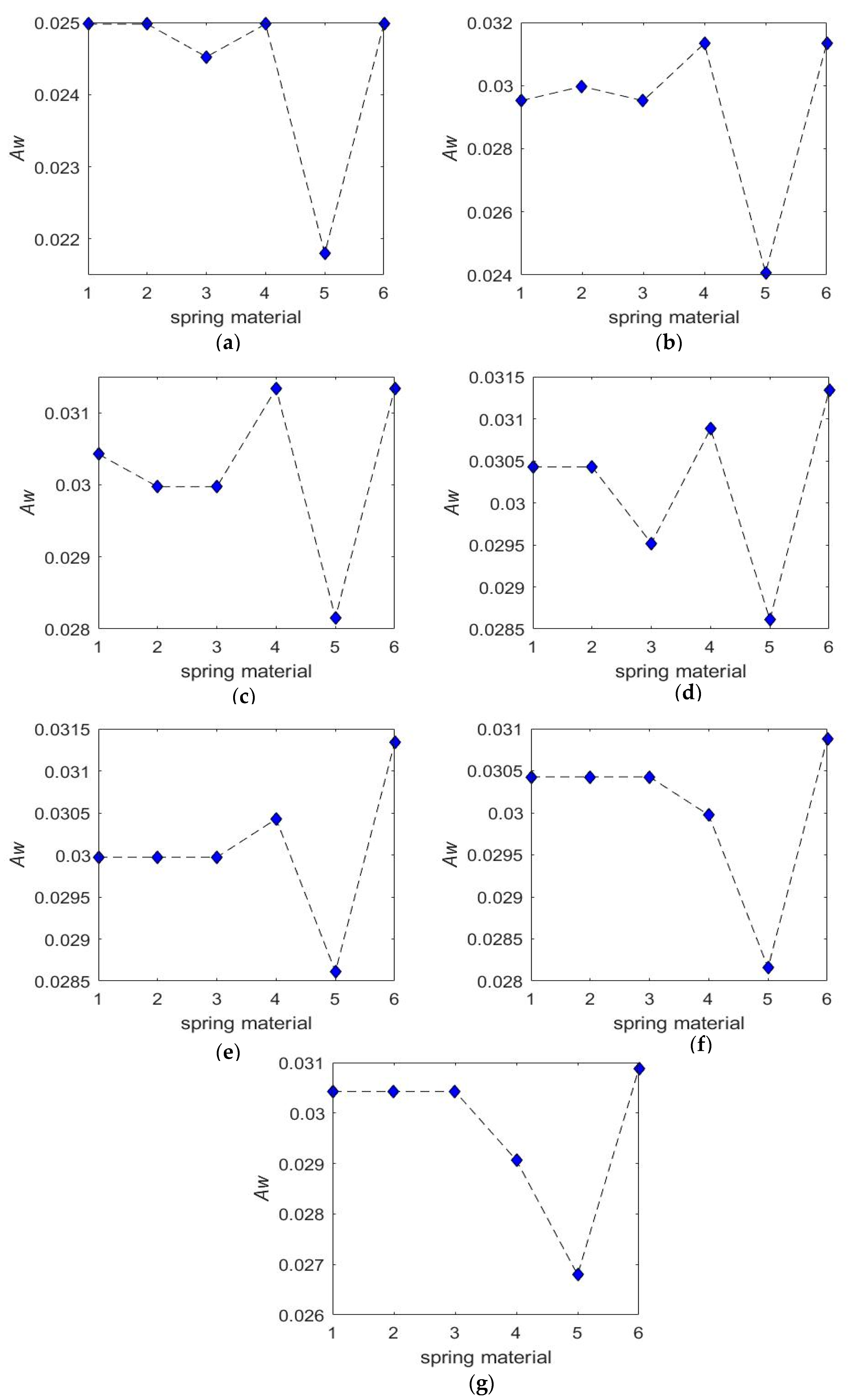
Figure 4.
Spring parameters (n, E/G) on CDHJ stiffness. (a) min() at n = 5; (b) min() at n = 8; (c) min() at n = 10; (d) min() at n = 13; (e) min() at n = 16; (f) min() at n = 20; (g) min() at n = 25.
Figure 4.
Spring parameters (n, E/G) on CDHJ stiffness. (a) min() at n = 5; (b) min() at n = 8; (c) min() at n = 10; (d) min() at n = 13; (e) min() at n = 16; (f) min() at n = 20; (g) min() at n = 25.

Figure 5.
Spring stiffness at n = 5 for No. 1 material.
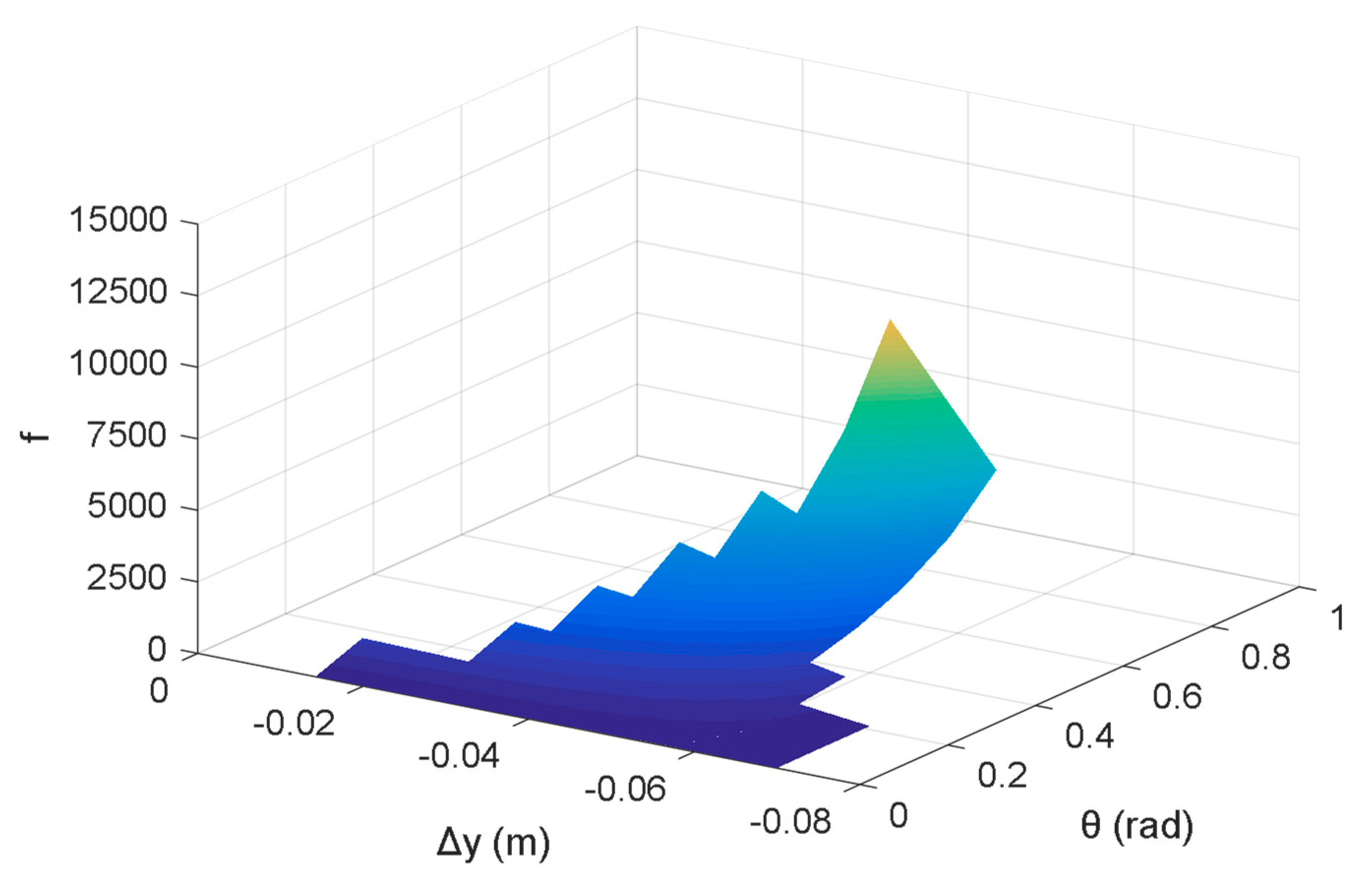
Figure 6.
Spring stiffness on CDHJ stiffness and cable tension at θ = −36°. (a) and at n = 5 for No. 1 material; (b) and at n = 5 for No. 1 material; (c) and at n = 10 for No. 4 material; (d) and at n = 10 for No. 4 material.
Figure 6.
Spring stiffness on CDHJ stiffness and cable tension at θ = −36°. (a) and at n = 5 for No. 1 material; (b) and at n = 5 for No. 1 material; (c) and at n = 10 for No. 4 material; (d) and at n = 10 for No. 4 material.

Figure 7.
Spring parameters (R, r) on CDHJ workspace. (a) Aw at r = 0.00075 m; (b) Aw at r = 0.001 m; (c) Aw at r = 0.00125 m; (d) Aw at r = 0.0015 m; (e) Aw at r = 0.00175 m; (f) Aw at r = 0.002 m.
Figure 7.
Spring parameters (R, r) on CDHJ workspace. (a) Aw at r = 0.00075 m; (b) Aw at r = 0.001 m; (c) Aw at r = 0.00125 m; (d) Aw at r = 0.0015 m; (e) Aw at r = 0.00175 m; (f) Aw at r = 0.002 m.

Figure 8.
Spring parameters (R, r) on CDHJ stiffness. (a) min() at r = 0.00075 m; (b) min() at r = 0.001 m; (c) min() at r = 0.00125 m; (d) min() at r = 0.0015 m; (e) min() at r = 0.00175 m; (f) min() at r = 0.002 m
Figure 8.
Spring parameters (R, r) on CDHJ stiffness. (a) min() at r = 0.00075 m; (b) min() at r = 0.001 m; (c) min() at r = 0.00125 m; (d) min() at r = 0.0015 m; (e) min() at r = 0.00175 m; (f) min() at r = 0.002 m

Figure 9.
CDHJ workspace at n = 10 for No. 4 material, R = 0.015 m, r = 0.0015 m.


Table 1.
Boundary values of variables.
| Parameters | Value |
|---|---|
| Tmin (N) | 1 |
| Tmax (N) | 300 |
| lmin (m) | 0.01 |
| xmin (m) | 0 |
| xmax (m) | 0.08 |
| θmin (rad) | −1.48 |
| θmax (rad) | 0 |
| ymin (m) | 0.035 |
| ymax (m) | 0.095 |
Table 2.
E/G of spring materials.
| Spring Materials | Mark | E (Gpa) | G (Gpa) |
|---|---|---|---|
| carbon spring steel wire, oil quenched-tempered spring steel wire, alloy spring steel wire, spring steel | 1 | 206 | 78.5 |
| stainless steel wire for spring (A) | 2 | 185 | 70 |
| stainless steel wire for spring (B), (C) | 3 | 195 | 73 |
| copper and copper alloy wire | 4 | 93.1 | 40.2 |
| beryllium bronze wire | 5 | 129.4 | 42.1 |
| spring-tempered steel | 6 | 195 | 81.5 |
© 2020 by the authors. Licensee MDPI, Basel, Switzerland. This article is an open access article distributed under the terms and conditions of the Creative Commons Attribution (CC BY) license (http://creativecommons.org/licenses/by/4.0/).
Share and Cite
MDPI and ACS Style
Zhang, S.; Sun, Z.; Lu, J.; Li, L.; Yu, C.; Cao, D. Spring Effects on Workspace and Stiffness of a Symmetrical Cable-Driven Hybrid Joint. Symmetry 2020, 12, 101. https://doi.org/10.3390/sym12010101
AMA Style
Zhang S, Sun Z, Lu J, Li L, Yu C, Cao D. Spring Effects on Workspace and Stiffness of a Symmetrical Cable-Driven Hybrid Joint. Symmetry. 2020; 12(1):101. https://doi.org/10.3390/sym12010101
Chicago/Turabian StyleZhang, Shan, Zheng Sun, Jili Lu, Lei Li, Chunlei Yu, and Dongxing Cao. 2020. "Spring Effects on Workspace and Stiffness of a Symmetrical Cable-Driven Hybrid Joint" Symmetry 12, no. 1: 101. https://doi.org/10.3390/sym12010101
Note that from the first issue of 2016, this journal uses article numbers instead of page numbers. See further details here.