Optimal Structural Design of a Magnetic Circuit for Vibration Harvesters Applicable in MEMS

1
CVVOZE Centre—Department of Theoretical and Experimental Electrical Engineering, Brno University of Technology, Technicka 12, 616 00 Brno, Czech Republic
2
SIX Centre—Department of Theoretical and Experimental Electrical Engineering, Brno University of Technology, Technicka 12, 616 00 Brno, Czech Republic
3
Department of Theoretical and Experimental Electrical Engineering, Brno University of Technology, Technicka 12, 616 00 Brno, Czech Republic
*
Author to whom correspondence should be addressed.
Symmetry 2020, 12(1), 110; https://doi.org/10.3390/sym12010110
Submission received: 28 November 2019
/
Revised: 16 December 2019
/
Accepted: 22 December 2019
/
Published: 6 January 2020
(This article belongs to the Special Issue Symmetry in Electromagnetism)
Abstract
:The paper discusses the results of research into a vibration-powered milli- or micro generator (MG). The generator harvests mechanical energy at an optimum level, utilizing the vibration of its mechanical system. The central purpose of our report is to outline the parameters that are significant for implementing the actual design to harvest the maximum (optimum) energy possible within periodic symmetrical systems, while respecting the typical behavior of the output voltage. The relevant theoretical outcomes influence the measurability and evaluation of the physical quantities that characterize the designed structures. The given parameters, which are currently defined in millimeters, are also applicable within the micrometer range, or MEMS. The article compares some of the published microgenerator concepts and design versions by using effective power density, among other parameters, and it also brings complementary comments on the applied harvesting techniques. The authors demonstrate minor variations in the magnetic rotationally symmetric circuit geometry that affect the pattern of the device’s instantaneous output voltage; in this context, the suitability of the individual design approaches that are to be used with MEMS as a vibration harvesting system is analyzed in terms of properties that are applicable in Industry 4.0.
1. Introduction
In recent years, alternative sources of energy have become the main subject of numerous research projects [1,2,3,4,5,6,7,8,9,10,11,12,13,14,15,16,17,18,19,20,21,22], with the optimum energy conversion being one of the central points of focus. Such a transformation is often ensured through a vibration microgenerator [23,24,25,26]. Effective energy harvesters exploiting the mechanical vibrations and related non-stationary magnetic fields have already been investigated and reported [2].
The comparative approach applied to harvesters for milli- or micro generators (MGs) within study [18] allows for an effective evaluation of different conversion concepts, namely, interpretations of Faraday’s law of induction. An optimal harvester design to yield the maximum power is obtainable via minor structural modifications that may substantially change the resulting performance while the parameters (including the weight, volume, and vibrations) remain virtually identical to those of standard harvesters. Different papers, including [2], detail functional magnetic circuits for vibration harvesters, where the model experiments and a comparison of various versions illustrate the effect of magnetic circuit modifications on the output voltage and power of a harvester. Advantageously, the devices can be grouped into periodic structures and also used in closed systems, such as automobiles, aircraft, and other units that are suitable for the inclusion of harvesters as additional and reliable energy sources. The possibilities of residual energy harvesting are examined in article [3]; the discussion comprises, among other aspects, specific harvester installation conditions, and requirements.
As regards the microgenerator design (Figure 1), Figure 2a introduces the most widely preferred principle (I, [2,3]); in the given context, it is necessary to respect the general conclusions of Faraday’s law of induction as formulated in, for example, Equation (1) and Figure 2b below. Figure 2 shows multiple processes and elements, including the magnetization of the permanent magnet M; magnetic flux Φ; magnetic lines of force; oriented area S enclosed by the coil thread; electric coil; and, character of the generator’s core motion with respect to the coil. The related Figure 2c then introduces a design version that minimizes the impact of external electromagnetic fields (non-stationary) on the principal function of the generator.
The generator was modeled to facilitate optimal design of the dimensions (minimum size and weight m) [2]. The vibrations measured with critical positioning of the device reached the maximum of G = 0.2 g (g = 9.81 ms−2). In the discussed concept, the resonance might vary, according to the origin of the vibrations, from the tuned resonance frequency fr by up to tens of percent.
As regards the optimum design variant, the critical parameter consisted in the boundary sensitivity of the generator to the minimum vibration amplitude; the relevant value corresponded to 0.01 g–0.05 g. In the following portions of the presentation, the proposed structural problems and methods for their solution will be discussed.
2. Designing the MG
The microgenerator utilizes an external environment that is characterized by the occurrence of mechanical vibrations, exploiting a suitable mechanical coupling to dampen these vibrations and generate an electric power Pout. The required output power Pout of the optimal design depends on the type of the output load Z. The optimal arrangement of the MG is based on the concepts in Figure 1, Figure 2c, and Figure 3, with the magnetization orientation indicated. In terms of the mechanical properties, the device was discussed in dedicated papers and patents, such as [10,25]. Figure 4 presents details of the transformation process and electricity generation; the actual engineering approach adopted in solving these procedures then embodies the necessary precondition for the subsequent identification of the optimal design. The mathematical model outlined in [2] is, in a basic form, incorporated in the corresponding Formula (5), below.
Figure 3, as above, presents one of the progressive options available for seating the moving part of the generator, a solution that eliminates the classic spring or girded beam (Figure 1). The designed system (Figure 3), is tuned to the mechanical oscillation resonance frequency fres and it constitutes the basis of the optimal approach. Such an arrangement allows for us to reach the maximum possible harvest rate and transform the field into an electric voltage; Figure 4 shows the corresponding preconditions.
3. Modeling the MG
To support our approaches, the paper includes fundamental parts of the relevant mathematical model, which is defined, for example, within referenced publications [1,2,3]. In the given context, the model can be formulated, as
where E(t) denotes the electric field intensity vector, B(t) is the magnetic flux density vector, v(t) represents the generator core position drift in time (the instantaneous velocity) vector, S stands for the cross section of the area with magnetic flux Φ, and l denotes the curve along the boundary of the S. Figure 4 illustrates the change of the magnetic flux of the field (ti1, …, ti4) and also the resulting induction of the voltage u. The behavior of the voltage u(t) can be evaluated by following the steps that are indicated in Figure 4; this behavior assumes the validity of Equation (1), magnetic flux Φ configuration, and electric coil shape with an active surface Sc.
We need to know the values of energy and transformation rate to be able to evaluate the efficiency of the proposed design (Figure 2c). The state equation can be defined with respect to the energy conservation law regarding the considered problem [1,2,3]. Subsequently, the kinetic and potential energies, Wk and Wp, respectively, which are related to the movement of the generator’s core, can be defined as
where m is the mass of the MG system, v denotes the mean velocity, and g represents the gravity constant.
The equation of state used by the authors of [1] and [2] captures the electromechanical coupling in the device, being expressed as
where dz/dt is the moving part drift in time, further measurable as the velocity v; η represents the magnetic field transformation efficiency; n denotes the normal vector; γ is the specific conductivity of the wire; ℓ is the length of the shift caused by the specific strength; B denotes the magnetic flux density vector; J represents the current density vector; VJc stands for the coil wire volume; and, VJ is the volume of the electrically conductive components. The MG system then also includes the braking forces
where is the acceleration of the moving part, denotes the velocity v of the moving parts, m represents the mass, k stands for the stiffness coefficient, lc is the damping coefficient, and Fz is the forces affecting the moving parts. The simplified model is described as
where Bbr is the braking magnetic flux density, Jv denotes the current density of the electrically conductive components, Jcirc represents the current density in the coil winding, and i stands for the instantaneous value of the current through the coil. The geometrical model that is applied in ANSYS (Version 12, ANSYS inc., Houston, USA) is presented in sources [23], ref. [2] as well as Figure 3a and Figure 5a. Figure 6, as below, shows the typical analysis of the ANSYS numerical model. The novel (optimal) generator design was tested on both a pneumatic and an electrodynamic shaker to verify the magnetic independence of the proposed solution. The magnetic circuit is designed such that its structure is enclosed within the body of the generator, ensuring reduced sensitivity to the external magnetic field and its changes. This parameter is of interest for application in the periodic structure of the outlined design usable in MEMS. The assumptions embodied in the variant from Figure 2c were experimentally verified.
4. Selecting the MG Core Design
Within the design of the generator, the ANSYS system [4] was used for the numerical analysis and to optimize the key parts. A mathematical model exploiting partial differential equations further described the electromagnetic field distribution [1,2]. This model becomes evident from Formulas (3), (5); the non-linear equations, which define the behavior of the external electric circuit [1,2,3]; and, the mechanical model of the main parts of the generator. There is mutual action between the mechanical and the electromagnetic effects. The partial differential equations of a coupled electro-mechanical circuit [4,5] were used to build the physical model.
A simplified model was employed to design the generator components. The model utilized lumped parameters, as shown in Figure 7, and it also assumed various versions of the magnetic field changes described with respect to the phase perspective, as indicated in Figure 4a–g. The individual parts, comprising the permanent magnet, air gap, electrical winding, magnetic circuit, electric coil, one turn of the winding, pole extension, beam, body, and core of the magnetic part of the generator, are denoted by using the reference symbols in Figure 7a.
A lumped parameters model can describe these components in order to perform quick assessment of the properties of the proposed concept. The above structures are classifiable into two groups: One of these exploits the approach where a magnetic field moves with respect to a fixed coil, as shown in Figure 7b; the other then utilizes an electric coil moving with respect to a stationary magnetic field and fixed to the body of a generator. Regarding the above analysis, we also examine the concept of a magnetic field moving with respect to an electric coil fixed to the body of a generator based on principle II (Figure 3a), in which the ferromagnetic circuit is fully closed and its components do not move against each other.
The generator design versions were used to build a series of models in ANSYS and then employed to examine the vibration energy harvesting rate. As a result, we can demonstrate the distribution of the magnetic flux density module B and the magnetic field intensity module H in Figure 6c of the functional sample according to the configurations that are presented in Figure 6a,b.
5. Critical Parameters of the MG Design
The critical parameters are outlined in sources [1,2,26] and can be categorized into the following areas:
- mechanical dynamics;
- electromagnetic field; and,
- electronic systems (power management blocks).
In terms of the mechanical dynamics, the optimal state depends on finding an interval of the mechanical approach to a vibration system for the known resonant frequency fres. Regarding this task, an aspect of major importance consists in the nonlinear stiffness coefficient k in the entire generator system (Figure 8). If the factor is adequately considered, then the device is capable of providing an operational efficiency of approximately 90%; in such conditions, the MG will operate at its maximum efficiency with minimal vibrations. The nonlinearity of the stiffness coefficient k depends on the choice of principal approach (Figure 1a,b and also Figure 6, Figure 7 and Figure 8).
Such an approach to the mechanical configuration of the MG is suitable for multiple purposes in microtechnology, including the formation of fields of resonant MGs (Figure 9, Figure 10, Figure 11 and Figure 12). Two approaches were tested as regards the electromagnetic field: one utilizing air to substitute for the ferromagnetic material in the magnetic field (principle II, Figure 1b), and the other applying a ferromagnetic material according to Figure 3a. Figure 9 demonstrates a solution to facilitate the further development of the progressive concept (principle II) through changes of the dimensional parameters of the design, t1, t2, ϕD1 − ϕD3.
6. Microstructures
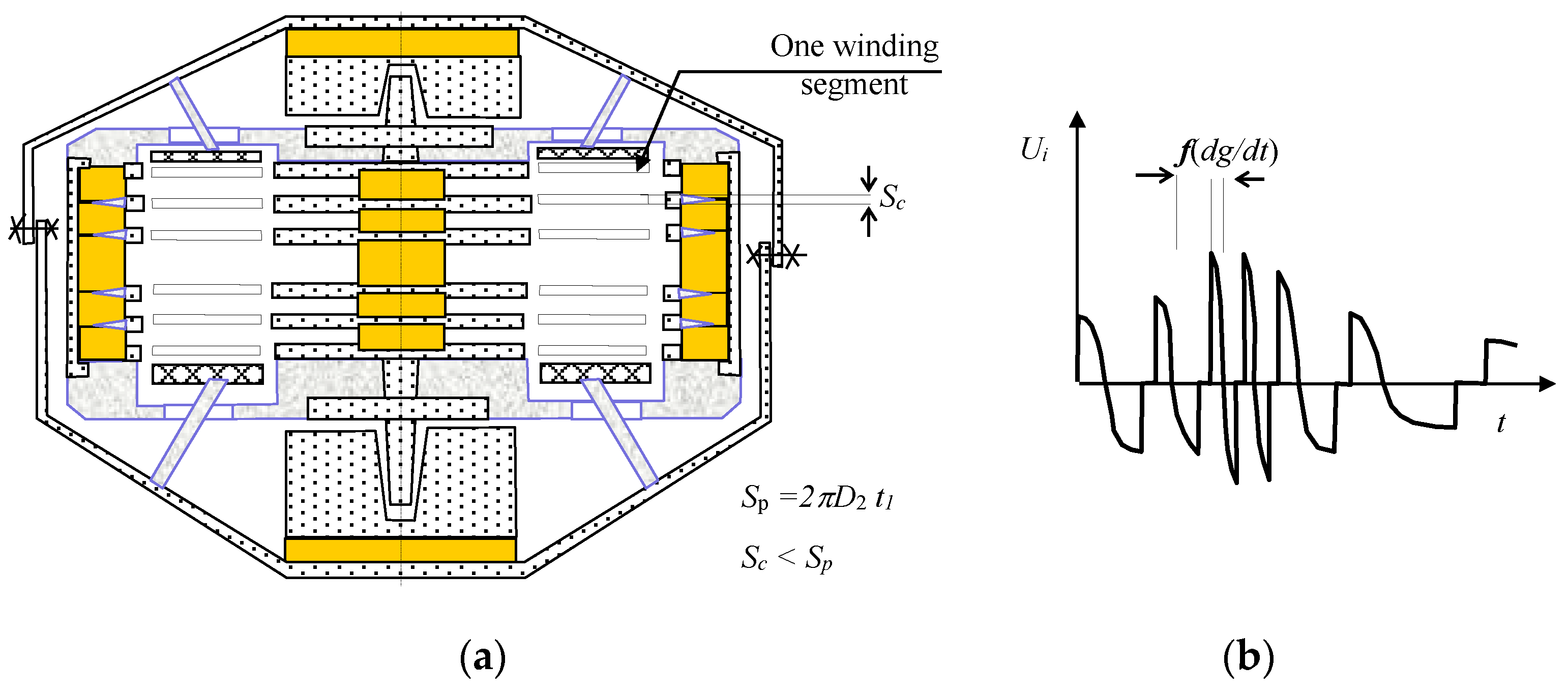
In order to apply the above-defined principles and conclusions, we have to consider the relevant figures (MG principle II, Figure 1b, Figure 3a and Figure 9, Figure 10, Figure 11 and Figure 12, where Sc is the effective area of the coil, Figure 2c; Sp denotes the area of the pole extension; t1 represents the thickness of the pole extension of the MG core; Nseg is the number of the electrical winding segments; Npol is the number of the pole extensions of the core and shell; and, f (dg/dt), g (dg/dt) denote the time variation of the gravitational acceleration of the moving part of the microgenerator. The correct setting of the MG0 structure, Figure 9, Figure 10 and Figure 11, can be verified through measuring or evaluating the behavior of the output voltage on the terminals of the MG segment. The obtained instantaneous values of the patterns of the voltage u(t) are then applicable in expressing, via the indirect method and based on the above formula (5), the observed physical quantities of the model.
As regards vibration energy harvesting within the microdimension, it is necessary to utilize in the MG fields the discussed principle II (Figure 7), together with certain variants of the relevant configurations of the magnetic circuit and winding (Figure 9, Figure 10, Figure 11 and Figure 12). Thus, the preset requirements for the generator sensitivity and effective use of the space will enable us to harvest a high amount of residual energy. Figure 13, below, illustrates an exemplary periodic MG structure. The actual design (Figure 10, Figure 11 and Figure 12) or other parameters can be altered to ensure the desired shape of the output voltage (Figure 10b, Figure 11b and Figure 12b) and also the conversion effectivity rate in transforming the mechanical vibrations to electrical energy.
The optimal design of a symmetrically structured sensitive vibration harvester (principle II, Figure 1b to operate in the resonant band can be applied in segmentation into microgenerator structures, as in Figure 13). Segmented microgenerators clustered as units (a MEMS harvester) can be arranged into fields. In this type of configuration, the designer has to consider the condition in which the length of the excitation vibration wave is
where L denotes the length of a side of the periodic structure, ls represents the length of the MG element, and lh is the space between the elements of the periodically structured field of microgenerators. During the propagation of vibrations, the structure behaves such that the electric voltage is almost in phase at the output of the windings.
The actual engineering of the procedure to facilitate, especially in terms of the size, the transition from a minigenerator to a microdevice (MEMS) is accompanied by not only technological questions and problems, but also the fundamental requirement of respecting the principles that are characterized in this paper. Generally, it is possible to suggest that the set of usable magnetic materials comprises items such as nano Ni and convenient permalloys deposited via sputter coating or lamination. The weight of the flat structure, ms, then determines the achievable resonant frequency, harvesting efficiency, and adjustment of the harvester’s lower sensitivity limit. Importantly, each concrete application of the principle requires designing a suitable MEMS structure by using the above-shown models.
7. Comparing MG Concepts, Designs, and Structures
Current experiments with vibration microgenerators converting energy via magnetic induction (vibration/electric energy) employ various harvesting approaches (principle I, principle II) and magnetic circuit structures [2]; thus, the devices exhibit diverse output power and conversion efficiency rates with respect to the given size and vibration frequency spectrum [12,13,14,15,16,17,18,19,20,21,22]. When engineering a periodic microstructure, a designer has to consider the degree of efficiency at which the transformed energy (mechanical vibrations) is to be harvested, and they then select the microstructure element accordingly, while utilizing available technologies. Several specific methods and the obtained results by different research groups are compared below, Figure 14, Figure 15, Figure 16, Figure 17 and Figure 18; in this context, the relevant concepts and structures of vibration generator transformation elements applied internationally are also discussed in view of the samples MG I–MG IV presented herein (Figure 19, Figure 20 and Figure 21).
The microgenerators that are characterized in Figure 14, Figure 15, Figure 16, Figure 17 and Figure 18 correspond to the concepts and design versions of the vibration generator magnetic circuit and housing outlined by the authors of this paper. The solution from Figure 2a corresponds to the embodiments that are discussed within articles [14,15], comprising a clearly open magnetic circuit and an induction coil unfavorably positioned with respect to the movement of the permanent magnet. The concepts and tests that are presented in [11,13] relate to the configuration from Figure 2b, where the induction coil is positioned and oriented such that the harvester provides a higher efficiency; however, the magnetic circuit is not markedly closed. The technique adopted by Yang et al. [16] approaches the effective configuration from Figure 2c; the researchers employed the non-linear, non-monotonous function of the stiffness coefficient k, namely, the function specified as the solution respecting Principle I, Figure 1a). By contrast, Beeby et al. [12] proposed an interpretation that, when compared to our investigation, resembles the system stiffness coefficient within Principle II–Figure 1b.
At the DTEEE FEEC, BUT, comparative tests were performed of a vibration generator (Figure 19) with magnetic damping [2] of the mobile arm’s movement; these testing cycles comprised design variants MG I–MG II according to Principle I and also versions MG III–MG IV exploiting Principle II. The parameters obtained in selected generators are summarized in Table 1; a wider comparison is available in study [18] (as in table 4).
If application in microelectronics and periodic systems is assumed, then the solution displayed in Figure 2c appears to be advantageous; however, at major vibrations, namely, ones between 0.3 g and 1.0 g, it is beneficial to configure the magnetic circuit and coil as set out within Principle I, Figure 1a). Where the external vibrations drop below 0.3 g (0.01 g–0.2 g), Principle II, Figure 1b, has to be applied. A generator configuration design requires an analysis of the magnetic field expected for the active section of the device and overall presetting of the maximum values of the specific magnetic flux density B into the air gap that is to contain the generator winding, Figure 6; such an analysis and presetting have to facilitate the maximum magnetic flux change in time and space, as formulated within Faraday’s law of induction (1) and to enable geometrical configuration of the winding shown in Figure 4. In the given context, it is advantageous to employ the double action system to facilitate a magnetic flux change, as indicated in Figure 5a and Figure 7.
Figure 20 presents the tested generators MG I–MG II that exploit Principle I and the energy harvesting efficiency rates yielded from Figure 2c, exhibiting various size versions together with different parameters and measured patterns of the output electrical voltage Uout.
Figure 21 presents the embodiments of MG III and MG IV respecting the magnetic circuit configuration according to Principle II and the energy harvesting effectivity scheme that characterizes the variant from Figure 2c.
The last column of Table 1 comprises data that are related to effective power density [W/m3]; this quantity enables us to express the effectivity of individual generator concepts and structures as regards harvesting quality. The last four lines indicate a comparable quantity for fossil and nuclear fuels, batteries, and supercaps.
For comparison purposes, Table 1 contains a quantity denoted as “effective power density“; in this context, it would probably be interesting to also indicate the harvesting rate of the microgenerator, but such a task appears to be rather problematic. Although the efficiency of a resonant harvester can be preset to a desired level, as demonstrated via Formulas (1)–(5), the associated model (5), and the test cycles visualized in Figure 19,Figure 20 and Figure 21 the achievable efficiency rate markedly depends on the quality of the mechanical coupling between the vibration source, the power management unit, and other relevant parameters; our tests yielded final rates between 50 and 95%. The problem was analyzed by different authors already previously [2,3,4,5,24].
8. Conclusions
The paper discussed the outcomes of a theoretical investigation into the design and principles of mini/micro generators to facilitate mechanical vibration energy harvesting [2]. The main product of the continuous research consists in simulation-based determination of the optimum rotationally symmetric geometry design versions and parameters of a relevant magnetic circuit.
The advantageous solutions and options are embodied in the generator design versions according to the proposed principles I and II, which ensure the necessary resistive loads and associated impedances. Exploiting the measured output voltages of the selected variants, the derived theoretical models can evaluate the harvester quality and fabrication procedure. Using the hybrid measurement approach combined with a numerical model, it is possible to classify other physical quantities of the electromagnetic field inside the generator.
The harvesters fabricated according to principle II, utilized in the range of fr = 10–50 Hz (frequent in the automotive and aeronautics sectors), are integrable into miniaturized microgenerator structures working within the range of G = 0.05 g–0.08 g. This concept could advantageously employ in practice the higher level of vibrations available compared to the design based on principle I [3]. The generators that employ principle I operate at vibration levels higher than G ≥ 0.15 g. Generally, the winding configuration variants convenient for the frequency ranges of fv = 1–10 Hz, fv = 50–150 Hz are demonstrated in Figure 2b,c.
We discussed selected samples of microgenerators to evaluate multiple quantities, including the effective power density (Table 1). This quantity is utilized as the parameter enabling us to choose the source of energy applicable in the given task or unit and determine whether the actual selection of the correct approach is a parameter for facilitating effective designing of MEMS structures. The knowledge that was obtained through the experiments is beneficial for the use of autonomous electro-mechanico-electronic systems in Industry 4.0 projects.
Author Contributions
P.F. contributed to the theoretical part, numerical model, and experiments; he also wrote the paper. Z.S. conceived and designed the experiments; J.D. contributed to the optimization procedures; and P.D., J.Z. evaluated the experiments and graphics. All authors have read and agreed to the published version of the manuscript.
Acknowledgments
The research was financed by the National Sustainability Program under grant No. LO1401 and supported within a grant of Czech Science Foundation (GA 17-00607S). For the actual analyses and experiments, the infrastructure of the SIX Center was used.
Conflicts of Interest
The authors declare no conflict of interest. The founding sponsors had no role in the design of the study; in the collection, analyses, or interpretation of data; in the writing of the manuscript, and in the decision to publish the results.
References
- Stratton, J.A. Theory of Electromagnetic Field; Czech Version; SNTL: Praha, Czech Republic, 1961. [Google Scholar]
- Szabo, Z.; Fiala, P.; Dohnal, P. Magnetic circuit modifications in resonant vibration harvesters. Mech. Syst. Signal Process. 2018, 99, 832–845. [Google Scholar] [CrossRef]
- Fiala, P. Vibration Generator Conception; Research Report in Czech; DTEEE, Brno University of Technology: Brno, Czech Republic, 2003; p. 95. [Google Scholar]
- Jirků, T.; Fiala, P.; Kluge, M. Magnetic resonant harvesters and power management circuit for magnetic resonant harvesters. Microsyst. Technol. 2010, 16, 677–690. [Google Scholar] [CrossRef]
- Fiala, P.; Jirků, T. Analysis and Design of a Minigenerator, Progress in Electromagnetics 2008. In Proceedings of the PIERS 2014 in Guangzhou, Guangzhou, China, 25–28 August 2014; pp. 749–753. [Google Scholar]
- Madinei, H.; Khodaparast, H.H.; Adhikari, S.; Friswell, M. Design of MEMS piezoelectric harvesters with electrostatically adjustable resonance frequency. Mech. Syst. Signal Process. 2016, 81, 360–374. [Google Scholar] [CrossRef]
- Scapolan, M.; Tehrani, M.G.; Bonisoli, E. Energy harvesting using parametric resonant system due to time-varying damping. Mech. Syst. Signal Process. 2016, 79, 149–165. [Google Scholar] [CrossRef]
- Gatti, G.; Brennan, M.; Tehrani, M.; Thompson, D. Harvesting energy from the vibration of a passing train using a single-degree-of-freedom oscillator. Mech. Syst. Signal Process. 2016, 66, 785–792. [Google Scholar] [CrossRef] [Green Version]
- Davino, D.; Krejčí, P.; Pimenov, A.; Rachinskii, D.; Visone, C. Analysis of an operator-differential model for magnetostrictive energy harvesting. Commun. Nonlinear Sci. Numer. Simul. 2016, 39, 504–519. [Google Scholar] [CrossRef] [Green Version]
- Saravanan, S.; Dubey, R. Optical absorption enhancement in 40 nm ultrathin film silicon solar cells assisted by photonic and plasmonic modes. Opt. Commun. 2016, 377, 65–69. [Google Scholar] [CrossRef]
- Kulkarni, S.; Koukharenko, E.; Torah, R.; Tudor, J.; Beeby, S.; O’Donnell, T.; Roy, S.; Beeby, S. Design, fabrication and test of integrated micro-scale vibration-based electromagnetic generator. Sens. Actuators A Phys. 2008, 145, 336–342. [Google Scholar] [CrossRef] [Green Version]
- Beeby, S.P.; Torah, R.N.; Torah, M.J.; O’Donnell, T.; Saha, C.R.; Roy, S. A microelectromagnetic generator for vibration energy harvesting. J. Micromech. Microeng. 2007, 17, 1257–1265. [Google Scholar] [CrossRef]
- Zhu, D.; Roberts, S.; Tudor, M.J.; Beeby, S.P. Design and experimental characterization of a tunable vibration-based electromagnetic micro-generator. Sens. Actuators A Phys. 2010, 158, 284–293. [Google Scholar] [CrossRef] [Green Version]
- Elvin, N.G.; Elvin, A.A. An experimentally validated electromagnetic energy harvester. J. Sound Vib. 2011, 330, 2314–2324. [Google Scholar] [CrossRef]
- Wang, P.-H.; Dai, X.-H.; Fang, D.-M.; Zhao, X.-L. Design, fabrication and performance of a new vibration-based electromagnetic micro power generator. Microelectron. J. 2007, 38, 1175–1180. [Google Scholar] [CrossRef]
- Yang, J.; Yu, Q.; Zhao, J.; Zhao, N.; Wen, Y.; Li, P.; Qiu, J. Design and optimization of a bi-axial vibration-driven electromagnetic generator. J. Appl. Phys. 2014, 116, 114506. [Google Scholar] [CrossRef]
- Lee, B.-C.; Rahman, A.; Hyun, S.-H.; Chung, G.-S. Low frequency driven electromagnetic energy harvester for self-powered system. Smart Mater. Struct. 2012, 21, 125024. [Google Scholar] [CrossRef]
- Siddique, A.R.M.; Mahmud, S.; Van Heyst, B. A comprehensive review on vibration based micro power generators using electromagnetic and piezoelectric transducer mechanisms. Energy Convers. Manag. 2015, 106, 728–747. [Google Scholar] [CrossRef]
- Quinn, J.B.; Waldmann, T.; Richter, K.; Kasper, M.; Wohlfahrt-Mehrens, M. Energy Density of Cylindrical Li-Ion Cells: A Comparison of Commercial 18650 to the 21700 Cells. J. Electrochem. Soc. 2018, 165, A3284–A3291. [Google Scholar] [CrossRef]
- Liu, C.; Yu, Z.; Neff, D.; Zhamu, A.; Jang, B.Z. Graphene-Based Supercapacitor with an Ultrahigh Energy Density. Nano Lett. 2010, 10, 4863–4868. [Google Scholar] [CrossRef] [PubMed]
- Zhu, D.; Tudor, M.J.; Beeby, S.P. Strategies for increasing the operating frequency range of vibration energy harvesters. J. Meas. Sci. Technol. 2010, 21, 22001. [Google Scholar] [CrossRef]
- El-Hami, M.; Glynne-Jones, P.; White, N.; Hill, M.; Beeby, S.; James, E.; Brown, A.; Ross, J. Design and fabrication of a new vibration-based electromechanical power generator. Sens. Actuators A Phys. 2001, 92, 335–342. [Google Scholar] [CrossRef]
- ANSYS Users Manual, (1991–2019). USA. Available online: www.ansys.com (accessed on 1 July 2018).
- Fiala, P.; Hadas, Z.; Singule, Z.; Ondrusek, C.; Szabo, Z. A Vibrational Generator for Electric Energy Producing, (in CZ Vibrační Generator pro Výrobu Elektrické Energie). Patent No. 305591-CZ, 12 September 2006. [Google Scholar]
- Fiala, P. Fotovoltaický Element Zahrnující Rezonátor (A Photovoltaic Element with an Included Resonator). Patent No. 303866, 27 January 2011. [Google Scholar]
- Fiala, P.; Szabo, Z.; Marcon, P.; Roubal, Z. Mini-and Microgenerators Applicable in the MEMS Technology, Smart Sensors, Actuators, and MEMS VIII. Proc. SPIE 2017, 10246, 1–8. [Google Scholar] [CrossRef]
Figure 1.
The principal configuration of the core of the milli- or micro generator (MG): (a) a beam version, principle I; (b) a beam version, principle II [2].
Figure 1.
The principal configuration of the core of the milli- or micro generator (MG): (a) a beam version, principle I; (b) a beam version, principle II [2].

Figure 2.
The basic arrangement of the investigated rotationally symmetric geometry device exploiting Faraday´s induction law: (a) the classic solution; (b) the novel arrangement; and, (c) the option with a closed magnetic circuit to minimize (optimize) the impact of external magnetic fields [2].
Figure 2.
The basic arrangement of the investigated rotationally symmetric geometry device exploiting Faraday´s induction law: (a) the classic solution; (b) the novel arrangement; and, (c) the option with a closed magnetic circuit to minimize (optimize) the impact of external magnetic fields [2].

Figure 3.
The basic arrangement of the investigated device exploiting Faraday´s induction law: (a) the MG core; and (b) the magnetic flux density distribution along the z axis, line A-A.
Figure 3.
The basic arrangement of the investigated device exploiting Faraday´s induction law: (a) the MG core; and (b) the magnetic flux density distribution along the z axis, line A-A.

Figure 4.
The electric voltage induction in the applied coil, (a–g), according to Faraday´s law of induction [2].
Figure 4.
The electric voltage induction in the applied coil, (a–g), according to Faraday´s law of induction [2].

Figure 5.
A geometrical model of the tested MG [2]: (a) the core of MG; and, (b) the functional sample subjected to a shaker-based test of the double-action winding.
Figure 5.
A geometrical model of the tested MG [2]: (a) the core of MG; and, (b) the functional sample subjected to a shaker-based test of the double-action winding.

Figure 6.
A geometrical rotationally SYMMETRIC model of the MG0 based on principle II [2]: (a) the ANSYS geometrical model; (b) the core; and, (c) the optimal design, detailed distribution of the magnetic flux density module B [T].
Figure 6.
A geometrical rotationally SYMMETRIC model of the MG0 based on principle II [2]: (a) the ANSYS geometrical model; (b) the core; and, (c) the optimal design, detailed distribution of the magnetic flux density module B [T].
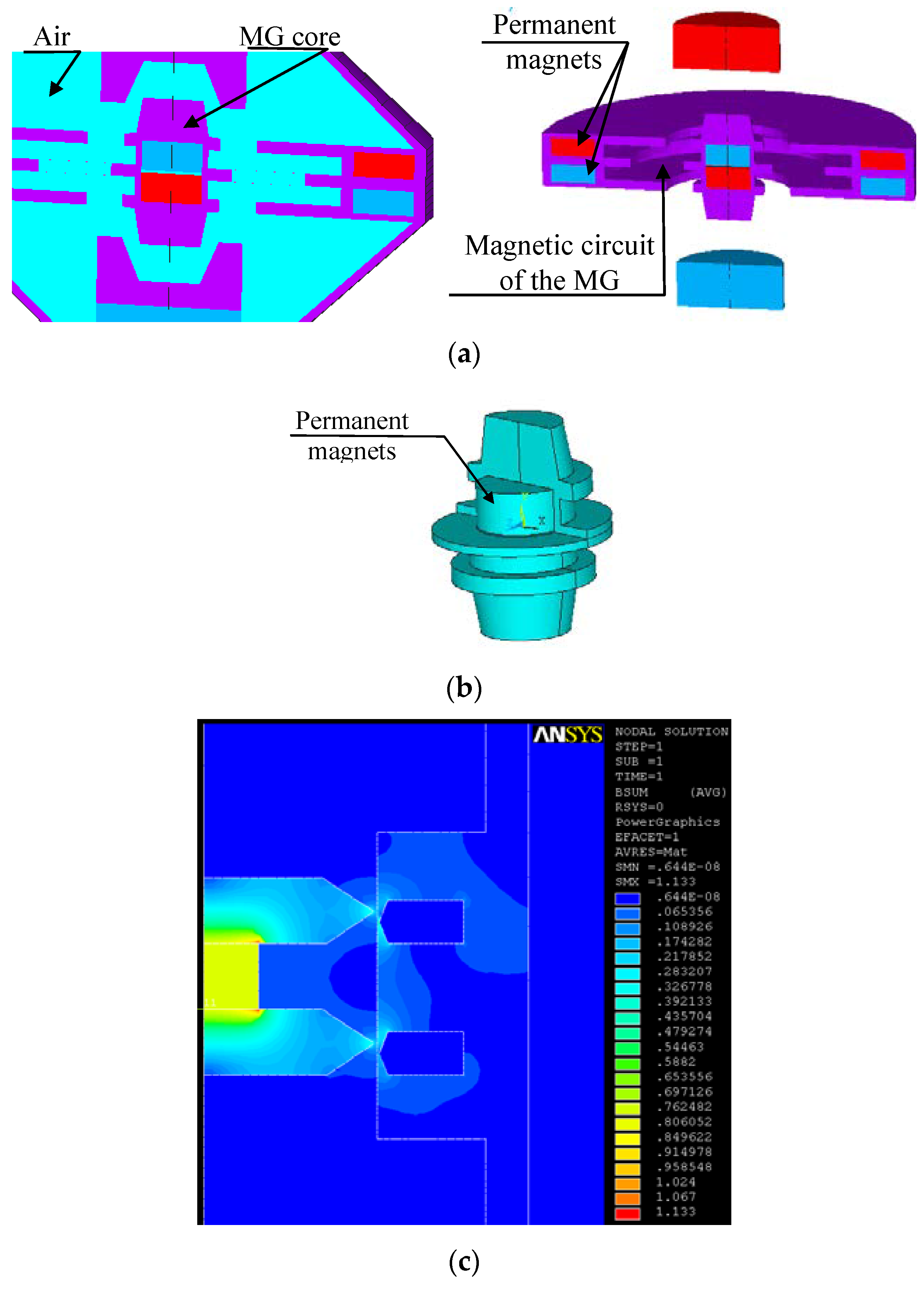
Figure 7.
The MG core with a ferromagnetic circuit according to principle II [2]: (a) a structurally simple variant, acceleration g within the interval of 0.01 g–0.3 g; (b) a scheme of the configuration.
Figure 7.
The MG core with a ferromagnetic circuit according to principle II [2]: (a) a structurally simple variant, acceleration g within the interval of 0.01 g–0.3 g; (b) a scheme of the configuration.

Figure 8.
The applied stiffness characteristics [2], coefficient k; the behavior is nonlinear in both of the MG magnetic circuit principles.
Figure 8.
The applied stiffness characteristics [2], coefficient k; the behavior is nonlinear in both of the MG magnetic circuit principles.

Figure 9.
A component diagram of the MG0 design with the linearized coefficient of stiffness k (based on principle II).
Figure 9.
A component diagram of the MG0 design with the linearized coefficient of stiffness k (based on principle II).

Figure 10.
A component diagram of the MG0 design with the linearized coefficient of stiffness k (based on principle II); (a) configuration A, and (b) its output voltage Uout.
Figure 10.
A component diagram of the MG0 design with the linearized coefficient of stiffness k (based on principle II); (a) configuration A, and (b) its output voltage Uout.

Figure 11.
A component diagram of the MG0 design with the linearized coefficient of stiffness k (based on principle II); (a) configuration B, and (b) its output voltage.
Figure 11.
A component diagram of the MG0 design with the linearized coefficient of stiffness k (based on principle II); (a) configuration B, and (b) its output voltage.

Figure 12.
A component diagram of the MG0 design with the linearized coefficient of stiffness k (based on principle II); (a) configuration C, and (b) its output voltage.
Figure 12.
A component diagram of the MG0 design with the linearized coefficient of stiffness k (based on principle II); (a) configuration C, and (b) its output voltage.

Figure 13.
A field of periodically configured MGs an exemplary structure.

Figure 14.
The silicon-based concepts developed by (a) Kulkarni et al. [11] and (b) Zhu et al. [13].

Figure 15.
The vibration microgenerator designed by Beeby et al. [12].
Figure 15.
The vibration microgenerator designed by Beeby et al. [12].
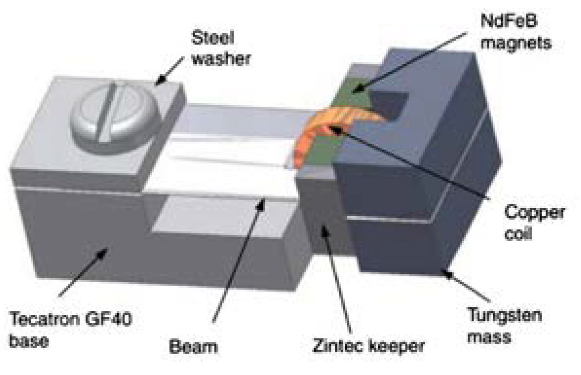
Figure 16.
The electromagnetic design by Wang et al. [15].
Figure 16.
The electromagnetic design by Wang et al. [15].

Figure 17.
The electromagnetic vibration energy harvester using cylindrical geometry, developed by Yang et al. [16].
Figure 17.
The electromagnetic vibration energy harvester using cylindrical geometry, developed by Yang et al. [16].

Figure 18.
The permanent magnet (a) having a spring in the cylindrical structure of the energy harvester [18], (b) tested sample designed by Lee et al. [17].

Figure 19.
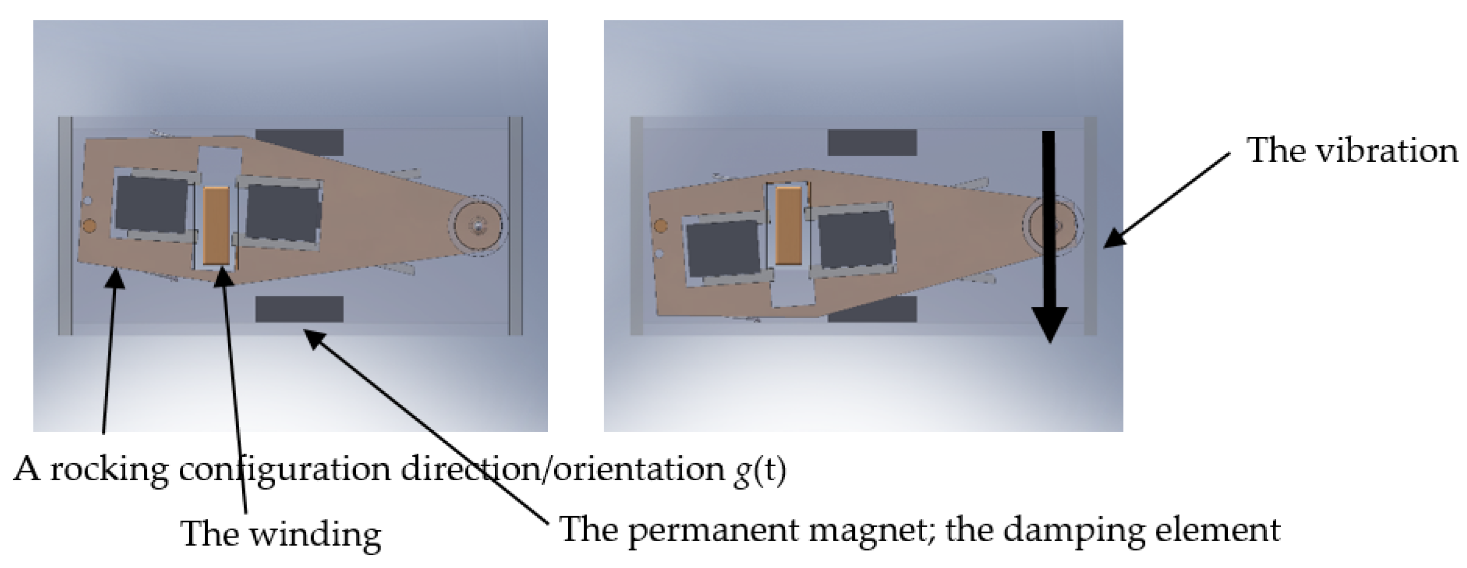
The basic symmetric magnetic circuit, structural design [2] according to Principles I and II, invariably with magnetic damping in the limit position of the rocking arm [3].

Figure 20.
The tested microgenerator [2] based on Principle I: (a) MG I—the dimensions of 90 × 40 × 30 mm, Uout max = 300 V; (b) MG II—the dimensions of 50 × 27 × 25 mm, Uout max = 20 V; and (c) the instantaneous behavior of the output electrical voltage in MG I and MG II (the effect of the stiffness coefficient k—Figure 8).

Figure 21.
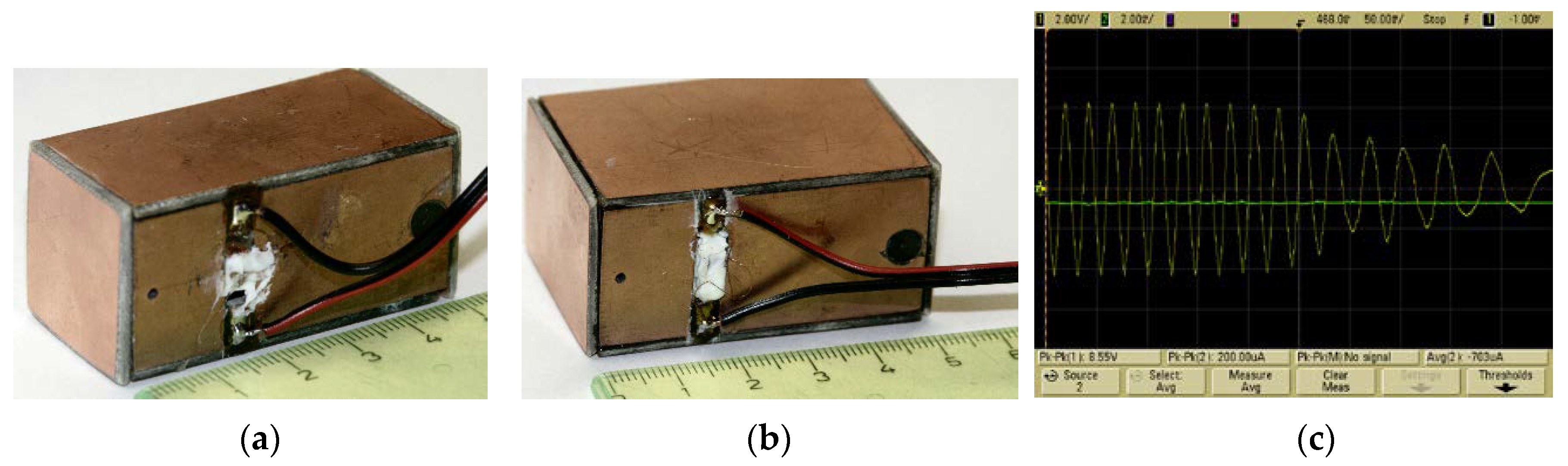
The devices based on Principle II [2]: (a) MG III—the dimensions of 50 × 25 × 25 mm, Uout max = 10 V; (b) MG IV—the dimesnions of 50 × 35 × 25 mm, Uout max = 20 V; and, (c) the instantaneous behavior of the output electrical voltage in MG III and MG IV (the effect of the stiffness coefficient k—Figure 8).
Figure 21.
The devices based on Principle II [2]: (a) MG III—the dimensions of 50 × 25 × 25 mm, Uout max = 10 V; (b) MG IV—the dimesnions of 50 × 35 × 25 mm, Uout max = 20 V; and, (c) the instantaneous behavior of the output electrical voltage in MG III and MG IV (the effect of the stiffness coefficient k—Figure 8).

Table 1.
The parameters of selected vibration generators.
| Reference | Permanent Magnet Type | Generator Body Size x, y, z [m] | Resonant Frequency fr [Hz] | Amplitude Mech. Part A [m] | Output Power Pout [W] | Output Voltage Uout [V] | Load Resistance R [Ω] | Acceleration G, g = 9.81 [m/s] | Effective Power Density [W/m3] |
|---|---|---|---|---|---|---|---|---|---|
| Beeby et al. [12], 2007 | − | 375 mm3 | 52 | − | 2 × 10⁻⁶ | 0.428 RMS | 4000 | 0.06 g | ≈6 |
| Zhu et al. [13], 2010 | FeNdB | 2000 mm3 | 67.6–98 | 0.6 × 10⁻³ | 61.6–156.6 × 10⁻⁶ | − | − | 0.06 g | ≈30–80 |
| Kulkarni et al. [11], 2008 | FeNdB | 3375 mm3 | 60–9840 | 1.5 × 10⁻³ | 0.6 × 10⁻⁶ | 0.025 | 52,700 | 0.398–4 g | ≈0.2 |
| Wang et al. [15], 2007 | FeNdB | 256 mm3 | 121.25 | 0.738 × 10⁻³ | - | 0.06 | - | 1.5 g | - |
| Lee et al. [17], 2012 | FeNdB | 1.4 × 10⁻⁴ m3 | 16 | − | 1.52 × 10⁻³ | 4.8 | 5460 | 0.2 g | ≈10 |
| Yang et al., [16], 2014. | − | 50,000 mm3 | 22–25 | 13.4 × 10⁻³ | 0.7–2.0 | 110 | 0.6 g | ≈270 | |
| Elvin et al., [14], 2011 | − | 15,000 mm3 | 112 | − | 4 × 10⁻⁶ | 0.007 | 986 | - | ≈0.26 |
| MG I [2], 2006 | FeNdB | 90, 40, 30 mm | 20–35 | 50 × 10−6–400 × 10−6 | 70 × 10−3 | 4–60 (300) p-p | 7500 | 0.15–0.4 g | ≈650 |
| MG II [2], 2006 | FeNdB | 50, 27, 25 mm | 17–25 | 50 × 10−6–400 × 10−6 | 19.5 × 10⁻³ | 6−15 | 5000 | 0.1–0.7 g | ≈60 |
| MG III | FeNdB | 50, 25, 25 mm | 21–31.5 | 50 × 10−6–400 × 10-6 | 5.0 × 10⁻³ | 1.0–2.5 | 600 | 0.05–0.4 g | ≈15 |
| MG IV | FeNdB | 50, 35, 25 mm | 21–31.5 | 50 × 10−6–400 × 10−6 | 8.0 × 10⁻³ | 1.0–2.5 | 1200 | 0.05–0.4 g | ≈18 |
| *Lith. battery [19], 2018 | ≈40 × 106 | ||||||||
| *supercap [20], 2010 | ≈3–5 | ||||||||
| *fuel | ≈4 × 10⁹ | ||||||||
| *U235 | ≈9 × 10¹⁶ |
© 2020 by the authors. Licensee MDPI, Basel, Switzerland. This article is an open access article distributed under the terms and conditions of the Creative Commons Attribution (CC BY) license (http://creativecommons.org/licenses/by/4.0/).
Share and Cite
MDPI and ACS Style
Szabó, Z.; Fiala, P.; Zukal, J.; Dědková, J.; Dohnal, P. Optimal Structural Design of a Magnetic Circuit for Vibration Harvesters Applicable in MEMS. Symmetry 2020, 12, 110. https://doi.org/10.3390/sym12010110
AMA Style
Szabó Z, Fiala P, Zukal J, Dědková J, Dohnal P. Optimal Structural Design of a Magnetic Circuit for Vibration Harvesters Applicable in MEMS. Symmetry. 2020; 12(1):110. https://doi.org/10.3390/sym12010110
Chicago/Turabian StyleSzabó, Zoltán, Pavel Fiala, Jiří Zukal, Jamila Dědková, and Přemysl Dohnal. 2020. "Optimal Structural Design of a Magnetic Circuit for Vibration Harvesters Applicable in MEMS" Symmetry 12, no. 1: 110. https://doi.org/10.3390/sym12010110
Note that from the first issue of 2016, this journal uses article numbers instead of page numbers. See further details here.