
Symmetric Heat Transfer Pattern of Fuel Assembly Subchannels in a Sodium-Cooled Fast Reactor
College of Energy and Mechanical Engineering, Shanghai University of Electric Power, Shanghai 201306, China
*
Author to whom correspondence should be addressed.
Symmetry 2022, 14(11), 2423; https://doi.org/10.3390/sym14112423
Submission received: 8 October 2022
/
Revised: 8 November 2022
/
Accepted: 10 November 2022
/
Published: 16 November 2022
(This article belongs to the Topic Nuclear Energy Systems)
Abstract
:The method outlined in this paper is convenient and effective for studying the thermal performance of fuel assemblies cooled with sodium fast reactors using the subchannel procedure. To initially study an optimization model for a symmetric single fuel assembly heat transfer pattern analysis in a fast sodium-cooled reactor based on subchannel calculations, this paper innovatively proposes a subchannel heat transfer analysis method with the entransy dissipation theory, which can solve the limitations and inaccuracies of the traditional entropy method such as poor applicability for heat transfer processes without functional conversion and the paradox of entropy production of heat exchangers. The symmetric distributions of the thermal-hydraulic parameters such as coolant flow rate, coolant temperature, cladding temperature, and fuel pellet temperature were calculated, and the entransy dissipation calculation method corresponding to the fuel assembly subchannels was derived based on the entransy theory. The effect of subchannel differences on the thermal-hydraulic parameters and the symmetric distribution pattern of entransy dissipation during the cooling process of the fuel assembly was analyzed and compared from the symmetrical arrangement of subchannels in the axial and radial directions.
1. Introduction
The sodium-cooled fast reactor (SFR) is the most promising and mature technology for generation IV nuclear systems [1]. The development of generation IV nuclear systems has received much attention from international scholars since they were proposed and have obvious economic and structural advantages over existing reactor types [2,3,4]. Compared to the other fourth-generation nuclear systems, SFR has richer operating experience and more mature technologies [5,6]. Given the great difference between liquid sodium and conventional fluids in the aspect of physical properties such as Pr number, the flow and heat transfer features of liquid metal sodium are different from the ordinary working media such as water, and have their particularity and complexity [6,7]. Reactor system parameters, including system pressure, heat flux density, and mass flow rate, are particularly critical to the operational safety and efficiency of the reactor [8]. Domestic and international scholars have analyzed the influence of system parameters on the wall temperature and heat transfer coefficient in the research of reactor core subchannels. Most of the existing researches have analyzed the heat transfer characteristics of the flow process of sodium coolant based on the cladding temperature, heat transfer coefficient, and flow resistance [9].
For the pool-type sodium-cooled fast reactor, the thermal-hydraulic design task of the reactor is to effectively take out heat under normal operating conditions and expected operating events according to the overall indicators of the power plant, so that the fuel does not melt and the fuel rods do not burn out [10]. Sufficient cooling can be provided under accident conditions and severe accident conditions to ensure that the release of radioactive substances from the reactor is limited within the allowable range and does not affect public safety [11]. As the core part of the thermal-hydraulic design of the reactor, the study of the thermal-hydraulic behavior of the core is very important, which is directly related to the safe operation of the entire reactor. Therefore, it is necessary to develop corresponding software modules to accurately simulate this behavior.
In view of the existing deficiencies in the classical heat transfer theory, Guo et al. [12,13] derived the heat transfer potential capacity and the heat transfer potential capacity dissipation function from a different perspective based on the nature of the heat transfer phenomenon. To consummate the existing heat transfer theory, a new physical quantity, termed as entransy, was brought forward by Guo et al. [12,13]. Its physical meaning corresponds to the total amount of heat transfer capacity and the rate of dissipation of heat transfer capacity. According to reference [12], entransy was once illuminated as a potential capacity in the heat transfer process. Henceforth, many scholars have applied entransy theory [14,15,16,17] to investigate and improve the heat transfer performances (HTPs) of various thermal systems [17,18]. The theory of entransy implements the optimization of the basis of heat transfer processes from the direction of analogy between heat and electrical conduction [19]. The heat transfer analysis shows that the entransy of an object describes its heat transfer capacity, as the electrical energy in a capacitor describes its charge transfer capacity. Entransy dissipation occurs during the heat transfer process as a measure of the irreversibility of heat transfer. The advent of the extreme value principle of entransy dissipation provides a completely different perspective for heat transfer optimization and solves the limitations and backwardness of the previous heat evaluation by virtue of entropy generation and thermal resistance as evaluation indicators, directly eliminating the defect of the entropy production paradox [20,21].
In contrast to the entropy production rate, the entransy dissipation rate is better suited to describe heat transfer, provided that the goal is not to minimize the dissipation of the work capacity. The principles of entransy and entransy dissipation extremes provide different directions and ideas for the optimization in heat transfer systems and can be used as a characteristic expression for analyzing the overall heat transfer capacity of the system [22]. In a study by Guo et al. [23], the heat dissipation problem of the wire insulation and the heat dissipation problem of the main parts of the housing were considered, and the results were optimized according to the principle of minimum heat dissipation potential (minimum dissipation rate). The results showed that the temperature gradient tends to be uniform, and the lower the heat transfer potential, the higher the heat transfer efficiency. Cheng et al. [23] compared two methods to minimize the entropy generation and minimize the dissipation of the transfer potential by numerical methods. The results show that the optimization results based on minimizing the heat dissipation potential dissipation can improve the heat transfer efficiency more effectively.
At present, scholars mostly use the traditional entropy production analysis method to evaluate the heat transfer of fast reactor cores, but there are many drawbacks. The entransy dissipation method is a new heat transfer analysis method, which focuses more on the energy transfer capacity loss. This paper innovatively proposes a subchannel heat transfer analysis method combining subchannel analysis and entransy dissipation theory, which can solve the limitations and inaccuracies of the traditional entropy method such as poor applicability for heat transfer processes without functional conversion and the paradox of entropy production of heat exchangers.
The temperature and velocity distribution of the fluid at the core scale can be calculated using this subchannel procedure. However, it still has its limitations. For improving the accuracy of subchannel calculation, much research is required in the subchannel process [24]. The subchannel procedure has been used in this article to simulate the cooling process of symmetrical fuel assembly of the sodium-cooled fast reactor. The thermal-hydraulic analysis of the subchannel and the study of the entransy dissipation law under the steady state of the reactor has been carried out, aiming to provide a heat transfer evaluation method based on the second law of thermodynamics and focusing on the symmetric thermal-hydraulic characteristics of the core, in addition to the existing conventional methods. In the subsequent study of the reactor heat exchange system, this method can be used as a reference for scholars and applied to engineering practice.
2. Numerical Methods
2.1. Mathematical Model
In this article, the sodium-cooled reactor, which has a high boiling point, does not boil when considering the design operating parameters of the conceptual reactor. The procedure therefore uses a single-phase flow model and does not consider flow and heat transfer in two phases [25]. Turbulent mixing processing uses the equal mass model, i.e., energy and momentum exchange between the subchannels is considered without considering mass exchange. Because it is the main factor affecting the hot channel enthalpy drop, introducing this model can improve the solution accuracy [26]. In this procedure, the subchannel division method formed by connecting the fuel rod centerline, vertical pipe wall line, and inner wall of the assembly is employed. Below is an analysis model of the procedure [24,27].
The mass conservation equation can be expressed as follows:
, , and are the flow area, the coolant density, and the axial mass flow rate of subchannel i [1]; is horizontal flow; is the height of axial control volume; t is the transient time of the process; and N is quantity of subchannels.
The energy conservation equation can be expressed as follows:
where is the enthalpy; is the turbulent mass flow rate; is the turbulent enthalpy; is the thermal conductivity factor; l is the turbulence length; T, Tn are the channel and adjacent channel temperatures; t is the transient time of the process; W is maximum difference in subscripts of adjacent channels; N is quantity of subchannels; qU is the heat transfer from the wrapper of the adjacent subchannels; λ is the thermal conductivity; and s is the gap length.
The axial momentum conservation equation can be expressed as follows:
where is the axial velocity; is the pressure; is the gravitational acceleration; is the angle between the flow and the vertical direction; is the frictional drag coefficient; is the channel hydraulic diameter; is the turbulent momentum factor; is the turbulent cross-mixing transverse flow; t is the transient time of the process; and W is maximum difference in subscripts of adjacent channels.
The transverse momentum conservation equation can be expressed as follows:
where is the adjacent channel pressure; is the cross-flow resistance coefficient; t is the transient time of the process; x is the axial position; and s is the gap length.
2.2. Physical Model
2.2.1. Fluid Physical Model
At ambient pressure, sodium has a melting point of 97.8 °C, and liquid sodium has flow properties similar to water, but its thermal conductivity exceeds that of water by two orders of magnitude and is therefore a very important source of methane. Since sodium has a boiling point up to 883 °C at ambient pressure, which is higher than the design temperature of the fast reactor and ensures the safety of the rapid reactor, it makes great sense for liquid metal sodium to act as a good coolant in the rapid reaction vessel. Most international-built fast reactors have used liquid metal sodium as the coolant to date. In this study, sodium physical properties used include density, isobaric specific heat capacity, dynamic viscosity, and thermal conductivity, as listed in Table 1 [28].
2.2.2. Heat Convection Model
The Pr number of liquid metallic sodium is very low. Therefore, under certain conditions, it will show different heat transfer characteristics from other liquids. This unique heat transfer characteristic of liquid sodium is determined by its special physical properties. This is mainly reflected in the following aspects: flow characteristics; rheological properties; heat conduction properties; radiation characteristics; and anisotropy. Compared with normal fluids, liquid metals have different basic turbulent heat transfer characteristics from conventional fluids because of their large thermal conductivity, which is mainly molecular heat transfer, temperature boundary layer, and velocity boundary layer separation during convection heat transfer. Experimental study on the heat transfer performance of liquid sodium at different flow rates shows that the total heat transfer coefficient per unit of time tends to decrease with the increase in flow velocity, but the total pressure drop tends to increase. The results showed that the average Nusselt number in liquid sodium decreased with the increase in Reynolds number. The Pr ≤ 0.007 of liquid sodium indicates that the thermal conduction of liquid metallic sodium during convection heat transfer is not omitted in relation to the momentum–heat diffusion transfer process and may even be dominant in individual cases. This difference will eventually be reflected in the heat transfer dimensionless Nu number relationship, while the Dittus–Boetler formula, which ignores the effects of molecular heat conduction, works only for water and not for liquid metals with low Pr numbers. The convective heat transfer relationship for the cooling process of sodium-cooled reactors can be expressed as the following [29]:
The scope of application of this formula is 1.15 ≤ P/D ≤ 1.30, 10 ≤ Pe ≤ 5000. In Equation (5), P is the rod spacing, D is the outer diameter of the rod, and Pe is the Peclet number, which is a dimensionless value equal to the product of the Reynolds number Re and the Prandtl number Pr.
2.2.3. Friction Pressure Drop Model
Novendstern [30] built a semi-empirical model for fuel rod assembly with hexagonal wire wrap. An additional friction coefficient is used to reflect the wire wrap in the model. Considering the influence of fluid flow and pipe length on friction coefficient, the simplified calculation formula is applied to single and multi-pipe wire wrap. The method is easy to implement and has practical value in engineering. It can be used for reference in engineering design. Firstly, the pressure drop of smooth tube is calculated by Blasius relation. Then, multiplicator M is introduced to explain the problem of wire wrap, i.e.,
M is a function of flow parameters and structural parameters, which can be expressed as
The applicable range of the Novendstern model is 2600 < Re < 200,000, 1.05 < P/D < 1.42, and 8 < H/D < 96.
2.2.4. Subchannel Model
Based on the design parameters of the fuel assembly system for the sodium cold reactor, the operating pressure of the system was determined to be 0.43 MPa, and the inlet temperature of the sodium coolant at the bottom of the core was determined to be 360 °C. The inlet flow of the sodium coolant was uniformly distributed. In order to study the distribution of symmetric heat transfer performance in component subchannels under various operating conditions, it is necessary to establish relevant mathematical models and numerical solutions. In this paper, the model is validated and analyzed by taking CEFR of a single sodium cold fast reactor as an example. The CEFR fuel assembly model has a symmetric hexagonal structure. The model is divided into inlet segments and active zones. The model assumes equal inlet pressure for each channel.
According to the position and shape of each fuel rod, the subchannels can be divided into inner channel, side channel, and angle channel, as shown in Figure 1, and the basic parameters of the fuel assembly are given in Table 2.
The single fuel assembly consists of 61 fuel rods arranged in a triangle and individually numbered counterclockwise from the inside out in a filament position. At the same time, the coolant channel in the fuel assembly is divided into different subchannels, which are divided into internal channels, corner channels, and side channels according to the position of the coolant channel, which are divided into 126 subchannels. As shown in Figure 1, subchannel 1 is the corner channel, subchannel 4 is the side channel, and subchannel 55 is the internal channel. Each subchannel corresponds to an inner hole, and there is a certain degree of interference between the subchannels. There are 6 subchannels in the corner, 24 subchannels in the border, and 96 subchannels in the interior.
2.3. Entransy Dissipation Equations
The equations listed below are derived and calculated by combining the symmetrical geometric arrangement of the fuel assembly and the entransy dissipation theory.
2.3.1. Entransy Dissipation in Heat Transfer Process
Under the condition of the given parameters, using the definition formula of entransy flow, the entransy flow caused by heat transfer of the fuel rod can be deduced as follows:
C is the thermal cycle coefficient; q is the heat flux density between the cladding and the coolant; Tc is the cladding temperature; and is the axial pitch.
Since the entransy dissipation is a state variable, the change in the entransy dissipation of sodium fluid is calculated according to the flow parameters of sodium fluid. The increment of internal entransy dissipation of sodium fluid can be deduced as follows:
2.3.2. Entransy Dissipation in Flow Process
Assuming that the flow of sodium in the channel is caused by the pressure difference between the outlet and the inlet, and that the flow is in a stable adiabatic state, regardless of the effect of the enthalpy change on the entransy, it can be concluded as follows:
where is the fluid density; p is the pressure; and e is the specific entransy, i.e., the entransy per unit mass of fluid.
In the subchannels, considering only the entransy dissipation of the flow process, the above formula is combined to approximate the temperature of sodium by the average temperature of the fluid, and the entransy dissipation caused by the fluid resistance can be deduced as follows:
3. Results and Discussion
3.1. Thermal-Hydraulic Parameters of the Subchannels
3.1.1. Distribution of the Axial Power
The core power distribution is an approximately symmetrical cosine function along the axial direction, as shown in Figure 2, and the relative power is expressed by the normalization method. The peak power is about 0.4 m in the axial position and the peak factor is about 1.234. Under the action of the insulation layer, the power of both ends of the core increases, resulting in the corresponding power valley values in the range of 0–0.1 m and 0.7–0.8 m.
3.1.2. Distribution of the Coolant Temperature
Figure 3 shows the axial distribution of coolant temperatures in a total of 12 symmetrically arranged subchannels in three different areas of the fuel assembly, with orange lines representing the corner channels, purple lines representing the inner channels, and green lines representing the side channels. According to the results, the temperature of inner channel coolant increases with the increase in axial height, and the maximum temperature occurs at the outlet of the channels. There is a temperature gradient between the channels along the radial direction, and its size is related to the position of the region. The coolant temperature is higher in the subchannels near the interior, as the figure shows. The exit temperatures of the corner channels and the side channels are slightly lower than that of the inside channels. The larger the equivalent diameter of the subchannels, the larger the circulation area, resulting in better cooling effect of the channels. Among them, the corner channels show the best radial symmetry, and the inner channels and the side channels show different degrees of symmetry deviation.
3.1.3. Distribution of the Cladding Temperature
Figure 4 shows the axial distribution of cladding temperatures for a total of 12 symmetrically arranged fuel rods in three different areas of the fuel assembly, with orange lines representing the corner rods, purple lines representing the inner rods, and green lines representing the side rods. It is clear from the figure that the cladding temperature in the 0–0.1 m range tends to moderate due to changes in axial power distribution and coolant flow, while the cladding temperature in the 0.1–0.8 m range tends to moderate after a surge in the increase due to axial power distribution and reaches its maximum value at export. The cladding temperature of the inner fuel rods is significantly higher than that of the corner and side fuel rods, and the cladding temperature of the corner fuel rods is relatively low. The reason for this is that the temperature of cladding is higher in the channels with better cooling effect, while the temperature of cladding in other channels is also affected by the type of channel and shows great difference. Among them, the corner channels show the best radial symmetry, and the inner channels and the side channels show different degrees of symmetry deviation.
3.1.4. Distribution of the Hot Rod Temperature
Figure 5 shows the axial temperature distribution of the hot rods in the fuel assembly. The axial temperature distribution of the hot rod includes the center temperature of the fuel, the outer surface temperature of the fuel, the inner surface temperature of the cladding, the outer surface temperature of the cladding, and the temperature of the coolant. The peak fuel temperature is 692.46 °C and the maximum temperature difference between the center and the outer surface of the fuel rod is between 0.45 m and 0.55 m, with a value of 75.87 °C, where the effect of thermal stress fatigue loss on the structural strength of the core should be emphasized. As neutron moderation increases at the upper and lower ends of the core, the released energy of the fission reaction increases, as does the power at the end, resulting in a slight increase in temperature at both ends of the fuel rod. The peak temperature of the cladding is 580.03 °C, the temperature difference between the fuel rods is significant due to the thermal conduction resistance between the fuel rod and the cladding, and the temperature difference between the fuel rods is significant. The same trend is shown by the increase in the temperature of the fuel rod at both ends. The temperature of the coolant increased monotonously with the increase in axial height, and the maximum occurred at the outlet of the channel at 567.53 °C.
3.2. Entransy Analysis of Subchannels
3.2.1. Distribution of Fractional Entransy Dissipation
Figure 6 shows the axial distribution of fractional entransy dissipation in a total of 12 symmetrically arranged subchannels in three different regions of the fuel assembly. With the decrease in pressure along the axial direction to zero, the changing trend of fractional entransy dissipation in each channel is almost uniform, and the linear trend decreases in the range of 0–0.8 m. The fractional entransy dissipation of the side channel is obviously larger than that of the corner channel and the inner channel, and the fractional entransy dissipation of the corner channel is relatively small. The main reason is the influence of flow area and mass velocity in the side channel. The mass velocity in the corner channel increases slightly compared with that in the inner channel, but the effect is not as obvious as the temperature field in the inner channel. Among them, the inner channels exhibit the best radial symmetry in the fractional entransy dissipation, while the side channels exhibit obvious symmetry deviation.
3.2.2. Distribution of Coolant Entransy in Flow Process
Figure 7 shows the axial distribution of coolant entransy in the flow process in a total of 12 symmetrically arranged subchannels in three different regions of the fuel assembly. From the calculation results, it is obvious that there are great differences between the subchannels along the altitude direction. All channels are on the rise. The coolant entransy in the flow process of the side channel is obviously larger than that of the corner channel and the inner channel. The coolant entransy in the flow process of the corner channel is relatively small. The reason is that the flow area and mass flow of the side channel are larger than that of the corner channel and the inner channel. The coolant flow temperature and mass flow rate of the corner channel are the smallest, but the mass flow rate is larger than that of the inner channel. The corner channels exhibit the best radial symmetry in coolant entransy in the flow process, and the inner channels and the side channels exhibit different symmetric deviations. The symmetry deviation of the inner channels increases with the increase in axial height, while the symmetry deviation of the side channels decreases with the increase in axial height.
3.2.3. Distribution of Entransy Flow in Heat Transfer Process
Figure 8 shows the axial distribution of entransy flow in the heat transfer process in a total of 12 symmetrically arranged subchannels in three different regions of the fuel assembly. Because of the change in axial power and coolant flow, the entransy flow in the heat transfer process is similar to the power distribution. The entransy flow of the corner channel is obviously smaller than that of the side channel and the inner channel. The entransy flow of the side channel is relatively small. The reason is that the heated perimeter of the corner channel is smaller than that of the side channel and the inner channel, so the entransy flow is smaller, and the overall cooling effect of the inner channel is higher than that of the side channel. The corner channels exhibit the best symmetry in the aspect of entransy flow in heat transfer process, while the side channels and inner channels exhibit some symmetry deviation.
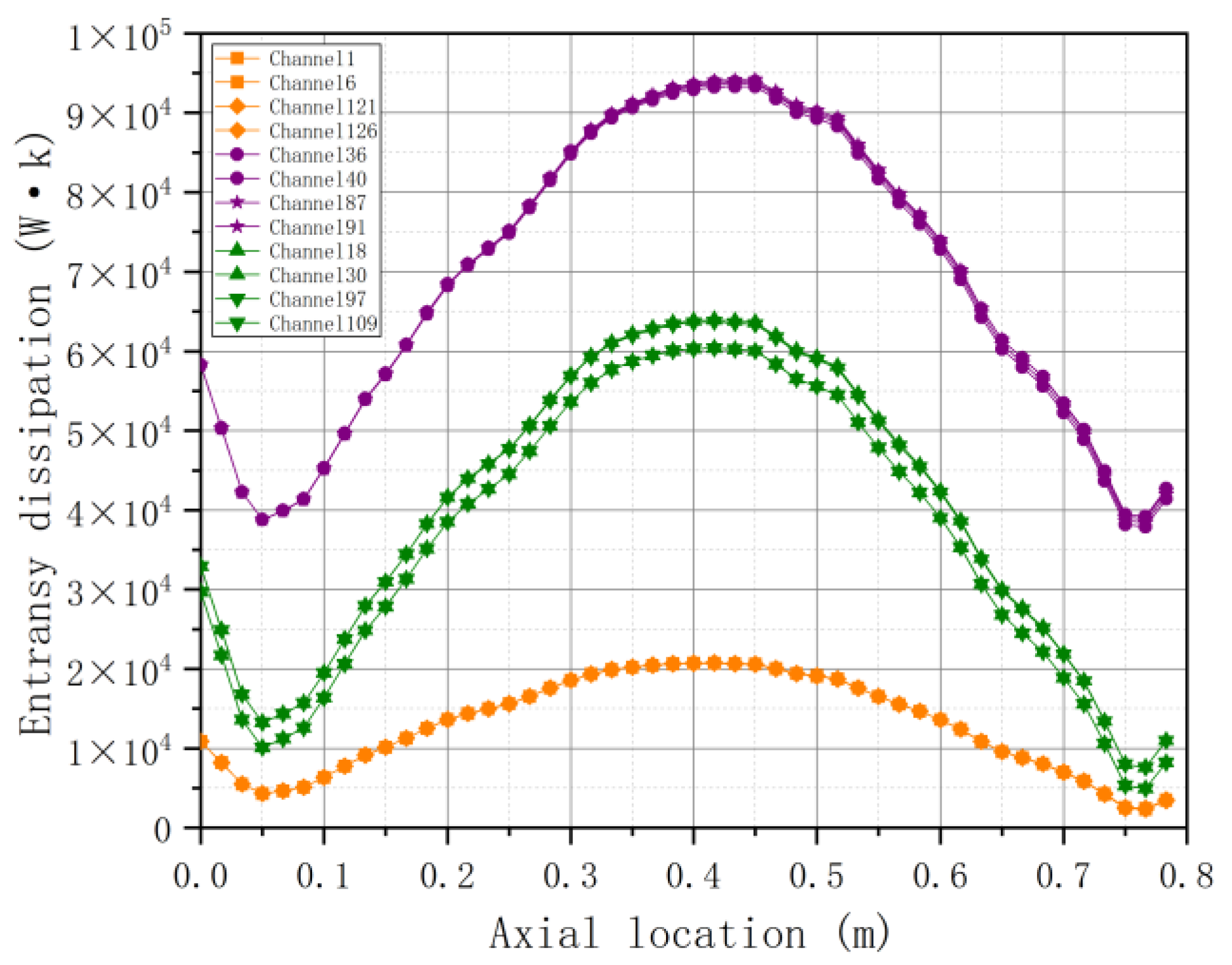
3.2.4. Entransy Dissipation Distribution of Subchannels
Figure 9 shows the axial distribution of entransy dissipation in a total of 12 symmetrically arranged subchannels in three different regions of the fuel assembly. It can be seen from the figure that the general trend is influenced by axial power distribution and the trend is relatively uniform. The entransy dissipation of the corner channel is obviously smaller than that of the side channel and the inner channel, and the entransy of the side channel is relatively small. The changing trend of entransy dissipation in the corner channel is the smoothest, which shows that the entransy dissipation is the least affected by power during the heat transfer in this channel. When the heated perimeter is constant, the entransy dissipation of the side channel is significantly lower than that of the inner channel. The reason is that the wet perimeter of the side channel is larger than that of the inner channel, which causes negative feedback. Among them, the corner channels and the inner channels exhibit the best symmetry, while the side channels exhibit obvious symmetry deviation.
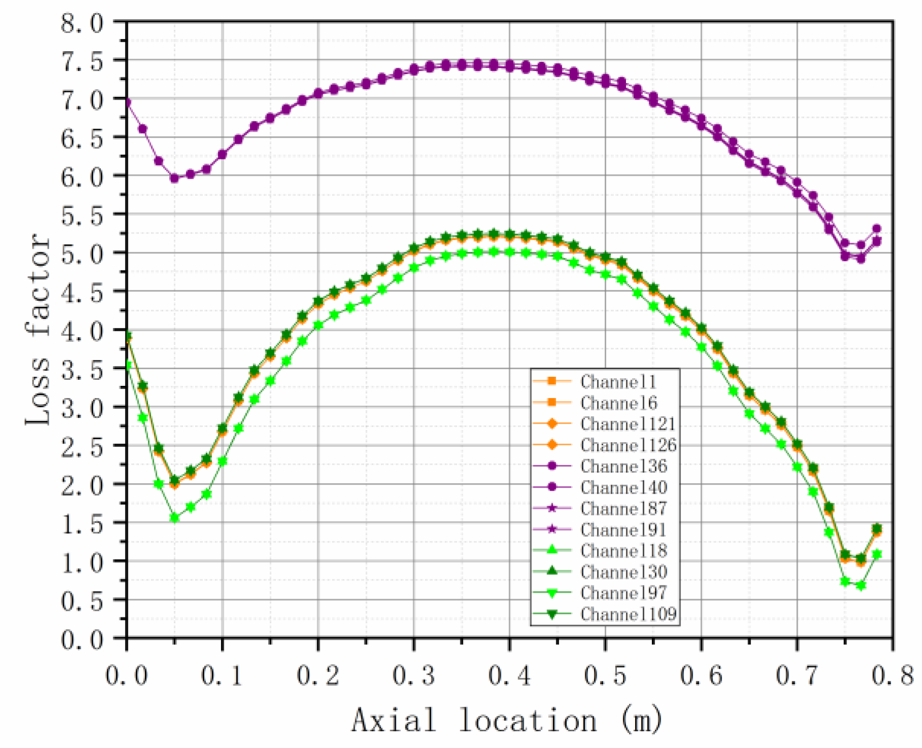
3.2.5. Entransy Loss Factor Distribution of Subchannels
Figure 10 shows the axial entransy loss factor distribution of subchannels in a total of 12 symmetrically arranged subchannels in three different regions of the fuel assembly. It can be seen that the entransy loss factor of the inner channel is obviously higher than that of the side channel and the corner channel, while the entransy loss factor of the side channel and the corner channel is similar, and the trend is basically the same. The inner channel has a larger heated perimeter and a smaller wet perimeter, which leads to larger entransy flow in the heat transfer process and smaller entransy flow in the flow process, so the entransy loss factor is larger than other channels.
However, the inner channel is least affected by the power and exhibits a more moderate axial symmetry. The entransy dissipation in the side channels is large, while the entransy loss factor is minimal, which is analyzed as negative feedback from its larger mass flow rate. Among them, the corner channels exhibit the best symmetry in terms of entransy loss factor, while the side channels and the inner channels exhibit some degree of symmetry deviation.
4. Conclusions
In this article, based on the subchannel procedure STAC, CEFR is chosen as the model for symmetry subchannel analysis to analyze the steady-state thermal parameters and entransy dissipation pattern. The results show that the Pu enrichment of the assembly determines the approximate symmetric cosine function distribution of the axial power, and further affects the assembly temperature and coolant flow rate. Therefore, the distributions of power, temperature, and coolant flow are approximately symmetric and M-shaped. The core coolant and cladding temperatures are monotonically increasing in the axial distribution and the peak temperatures are found at the exit. The internal temperature of individual assembly is sensitive to the axial power distribution, and there are valleys near the inlet and outlet. In addition, the larger the equivalent diameter of the circulation channel and the larger the circulation area, the better the cooling effect. The final calculation shows that the center temperature of the hot rod reaches 692.46 °C, which is lower than the melting point of nitride fuel. It illustrated that the use of sodium is safe and efficient for reactors. The validation shows that the results of the STAC thermal analysis program are in good agreement with the literature data and can be applied to the thermal-hydraulic analysis of the sodium-cooled fast reactor.
The fractional entransy dissipation is affected by the pressure drop in the subchannels, and the overall trend is the same decrease. The inner channel presents the best radial symmetry to the entransy dissipation. The coolant entransy in flow process of each channel is influenced by circulation area and mass flow rate, among which the corner channel shows the best radial symmetry for coolant entransy in the flow process. The entransy flow in the heat transfer process of each channel is significantly affected by the power distribution, among which the corner channel has the lowest response to the power, the subchannel has significantly different entransy flow in the heat transfer process with its different thermal perimeter, and the corner channel shows the best symmetry to the entransy flow in the heat transfer process. The subchannel entransy dissipation shows the trend of power distribution, mass flow rate, and channel structure together, in which the corner channel is affected by the power the least and the entransy dissipation is also the least, while the inner channel is affected by the mass flow rate and channel structure together. The corner channels and the inner channels exhibit the best symmetry in terms of the subchannel entransy dissipation. Due to the complex structure of the inner channel and lateral cross-mixing, the entransy loss factor of the inner channel is larger than that of the edge channel. The edge channel shows the best heat transfer performance with a low entransy loss factor corresponding to a larger entransy dissipation due to its large mass flow rate, while the corner channels exhibit the best symmetry in terms of entransy loss factor.
Author Contributions
Conceptualization and writing, C.H.; methodology, J.L.; investigation, L.H.; supervision, Z.D.; validation, X.N. All authors have read and agreed to the published version of the manuscript.
Funding
This research received no external funding.
Institutional Review Board Statement
Not applicable.
Informed Consent Statement
Not applicable.
Data Availability Statement
Not applicable.
Acknowledgments
The authors gratefully acknowledge the support of the College of Energy and Mechanical Engineering, Shanghai University of Electric Power.
Conflicts of Interest
The authors declare no conflict of interest.
References
- Yue, N.; Zhang, D.; Chen, J.; Song, P.; Wang, X.A.; Wang, S.; Qiu, S.; Su, G.H.; Zhang, Y. The development and validation of the inter-wrapper flow model in sodium-cooled fast reactors. Prog. Nucl. Energy 2018, 108, 54–65. [Google Scholar] [CrossRef]
- Wang, C.; Zhang, D.; Qiu, S.; Tian, W.; Wu, Y.; Su, G. Study on the characteristics of the sodium heat pipe in passive residual heat removal system of molten salt reactor. Nucl. Eng. Des. 2013, 265, 691–700. [Google Scholar] [CrossRef]
- Liu, L.; Zhang, D.; Lu, Q.; Wang, K.; Qiu, S. Preliminary neutronic and thermal-hydraulic analysis of a 2 MW Thorium-based Molten Salt Reactor with Solid Fuel. Prog. Nucl. Energy 2016, 86, 1–10. [Google Scholar] [CrossRef]
- Yang, H.Y. International forum on generation IV nuclear energy systems (GIF) progress in the development of sodium-cooled fast reactors. Annu. Rep. China Inst. At. Energy 2009, 1, 4–5. [Google Scholar]
- Chellapandi, P.; Velusamy, K. Thermal hydraulic issues and challenges for current and new generation FBRs. Nucl. Eng. Des. 2015, 294, 202–225. [Google Scholar] [CrossRef]
- Hou, Y.D.; Wang, L.; Wang, M.J.; Zhang, K.; Zhang, X.S.; Hu, W.J.; Wu, Y.W.; Tian, W.X.; Qiu, S.Z.; Su, G.H. Experimental study of liquid sodium flow and heat transfer characteristics along a hexagonal 7-rod bundle. Appl. Therm. Eng. 2019, 149, 578–587. [Google Scholar] [CrossRef]
- Qiu, Z.; Ma, Z.; Wu, Y.; Qiu, S.; Su, G. Experimental research on the thermal hydraulic characteristics of liquid sodium flowing in annuli with low Peclet number. Ann. Nucl. Energy 2015, 75, 483–491. [Google Scholar] [CrossRef]
- Gao, X.Z.; Ren, L.X. Numerical simulation study on thermal hydraulics of lead-bismuth fast reactor fuel assembly. Technol. Innov. Appl. 2019, 22, 4. [Google Scholar]
- Zhang, S.M.; Zhang, D.H. Development and verification of sub-channel analysis code for solid fuel core of sodium cooling fast reactor. At. Energy Sci. Technol. 2018, 52, 320–325. [Google Scholar]
- Liang, J.T.; Lu, D.G.; Zhao, H.Q.; Fu, J.P.; Yang, J.; Guo, Z.X.; Zhang, Y.H. Three-dimensional numerical simulation of pool-type sodium-cooled fast reactor double-loop 12% difference asymmetric power operation and flow regulation mitigation conditions. Sci. Technol. Eng. 2021, 21, 7. [Google Scholar]
- Zhang, Y.M.; Zhang, X.J.; Zhang, S.W.; Sun, J.B. Releasing and harmful analysis of active material in nuclear reactor on accident condition. Chem. Def. Ships 2014, 3, 1–7. [Google Scholar]
- Guo, Z.Y.; Zhu, H.Y.; Liang, X.G. Entransy—A physical quantity describing heat transfer ability. Int. J. Heat Mass Transf. 2007, 50, 2545–2556. [Google Scholar] [CrossRef]
- Cheng, X.T.; Liang, X.G. Work entransy and its applications. Sci. China Technol. Sci. 2015, 58, 2097–2103. [Google Scholar] [CrossRef]
- Chen, L.G. Progress in entransy theory and its applications. Sci. Bull. 2012, 57, 23. [Google Scholar] [CrossRef] [Green Version]
- Cheng, X.; Zhang, Q.; Liang, X. Analyses of entransy dissipation, entropy generation and entransy–dissipation-based thermal resistance on heat exchanger optimization. Appl. Therm. Eng. 2012, 38, 31–39. [Google Scholar] [CrossRef]
- Chen, L.; Xiao, Q.; Feng, H. Constructal Optimizations for Heat and Mass Transfers Based on the Entransy Dissipation Extremum Principle, Performed at the Naval University of Engineering; a Review. Entropy 2018, 20, 74. [Google Scholar] [CrossRef] [Green Version]
- Chen, X.; Zhao, T.; Zhang, M.Q.; Chen, Q. Entropy and entransy in convective heat transfer optimization: A review and perspective. Int. J. Heat Mass Transf. 2019, 137, 1191–1220. [Google Scholar] [CrossRef]
- Xie, Z.H.; Chen, L.G.; Sun, F.R. Comparative study on constructal optimizations of T-shaped fin based on entransy dissipation rate minimization and maximum thermal resistance minimization. Sci. China Technol. Sci. 2011, 54, 10. [Google Scholar] [CrossRef]
- Han, C.H.; Kim, K.H. Entransy and Exergy Analyses for Optimizations of Heat-Work Conversion with Carnot Cycle. J. Therm. Sci. 2016, 25, 242–249. [Google Scholar] [CrossRef]
- Chen, L.G.; Yang, A.B.; Feng, H.J.; Ge, Y.L.; Xia, S.J. Constructal design progress for eight types of heat sinks. Sci. China 2020, 63, 5–37. [Google Scholar] [CrossRef]
- Hoffmann, K.; Kulmus, K.; Essex, C.; Prehl, J. Between Waves and Diffusion: Paradoxical Entropy Production in an Exceptional Regime. Entropy 2018, 20, 881. [Google Scholar] [CrossRef] [PubMed] [Green Version]
- Liu, X.B.; Meng, J.A.; Guo, Z.Y. Heat exchanger thermal resistance analysis based on entransy dissipation. Prog. Nat. Sci. 2008, 10, 1186–1190. [Google Scholar]
- Cheng, X.G.; Meng, J.A.; Guo, Z.Y. Potential capacity dissipation minimization and entropy generation minimization in heat conduction optimization. J. Eng. Thermophys. 2005, 26, 1034–1036. [Google Scholar]
- Lin, C.; Yang, H.Y.; Chou, Z.W. Preliminary development of sub-channel code for the natural convection assembly of sodium cooled fast reactor. At. Energy Sci. Technol. 2021, 55, 9. [Google Scholar]
- Wang, X.K.; Qi, S.P.; Yang, J.; Ye, S.S.; Wang, L.X.; Feng, Z.R.; Zhong, D.T.; Jia, H.Y.; Yang, X.Y.; Liu, Y.Z.; et al. Development of system code FR-Sdaso for sodium cooled fast reactor. At. Energy Sci. Technol. 2020, 54, 9. [Google Scholar]
- Moorthi, A.; Sharma, A.K.; Velusamy, K. A review of sub-channel thermal hydraulic codes for nuclear reactor core and future directions. Nucl. Eng. Des. 2018, 332, 329–344. [Google Scholar] [CrossRef]
- Sha, W.T.; Schmitt, R.C.; Huebotter, P.R. Boundary-Value Thermal-Hydraulic Analysis of a Reactor Fuel Rod Bundle. Nucl. Sci. Eng. 2017, 59, 140–160. [Google Scholar] [CrossRef]
- Shan, J.Q.; Qiu, H.Z. Research on the derivation of the partial derivative formula of sodium physical properties for safety analysis. Nucl. Power Eng. 1997, 18, 6. [Google Scholar]
- Seo, H.; Kim, J.H.; Bang, I.C. Subchannel analysis of a small ultra-long cycle fast reactor core. Nucl. Eng. Des. 2014, 270, 389–395. [Google Scholar] [CrossRef]
- Novendstern, E.H. Turbulent flow pressure drop model for fuel rod assemblies utilizing a helical wire-wrap spacer system. Nucl. Eng. Des. 1972, 22, 28–42. [Google Scholar] [CrossRef]
Figure 1.
Subchannel division of fuel assembly.

Figure 2.
Distribution of the axial power.

Figure 3.
Distribution of the coolant temperature.

Figure 4.
Distribution of the cladding temperature.

Figure 5.
Distribution of the hot rod temperature.

Figure 6.
Distribution of fractional entransy dissipation.

Figure 7.
Distribution of coolant entransy in flow process.

Figure 8.
Distribution of entransy flow in heat transfer process.

Figure 9.
Entransy distribution of coolant flow process.

Figure 10.
Entransy distribution of coolant flow process.


Table 1.
Liquid sodium physical property relationship.
| Parameter | Unit | Value/Formula |
|---|---|---|
| Melting point | K | TM = 370.95 |
| Boiling point | K | TB = 1156.15 |
| Enthalpy of liquid | J/kg | hs = −6.7511 × 10⁴ + 1630.22 T ± 0.41674 T2 + 1.54279 × 10⁻⁴ T3 |
| Density | kg/m3 | ρ = 1011.6 ± 0.22051 T ± 1.92243 × 10⁻⁵ T2 + 5.63769 × 10⁻⁹ T3 |
| Isobaric specific heat | J/(kg·K) | Cp = 1630.22 ± 0.83354 T + 4.62838 × 10⁻⁴ T2 |
| kinetic viscosity | N∙s/m2 | μ = 10−2.4892 + 220.65 T−1 ± 0.4925 log10T |
| Thermal conductivity | W/(m·K) | λ = 109.7 ± 6.4499 × 10⁻² T − 1.1728 × 10⁻⁵ T2 |
Table 2.
Basic parameters of the fuel assembly.
| Parameter | Unit | Value/Description |
|---|---|---|
| Full length | m | 2.592 |
| Number of rods | root | 61 |
| Center distance | m | 7 × 10⁻³ |
| Full length of cladding | m | 1.313 |
| The outer diameter of cladding | m | 6 × 10⁻³ |
| The inner diameter of cladding | m | 5.4 × 10⁻³ |
| Coolant flow rate | m/s | <5 |
| Cladding material | / | CN-1515 |
| Maximum temperature of cladding | °C | 670 |
| Inlet and outlet temperature | °C | 360/530 |
| Maximum line power density | kW/m | 4.10 |
Publisher’s Note: MDPI stays neutral with regard to jurisdictional claims in published maps and institutional affiliations. |
© 2022 by the authors. Licensee MDPI, Basel, Switzerland. This article is an open access article distributed under the terms and conditions of the Creative Commons Attribution (CC BY) license (https://creativecommons.org/licenses/by/4.0/).
Share and Cite
MDPI and ACS Style
Huang, C.; Liu, J.; Hai, L.; Dong, Z.; Niu, X. Symmetric Heat Transfer Pattern of Fuel Assembly Subchannels in a Sodium-Cooled Fast Reactor. Symmetry 2022, 14, 2423. https://doi.org/10.3390/sym14112423
AMA Style
Huang C, Liu J, Hai L, Dong Z, Niu X. Symmetric Heat Transfer Pattern of Fuel Assembly Subchannels in a Sodium-Cooled Fast Reactor. Symmetry. 2022; 14(11):2423. https://doi.org/10.3390/sym14112423
Chicago/Turabian StyleHuang, Chao, Jianquan Liu, Lihan Hai, Zenghao Dong, and Xinyi Niu. 2022. "Symmetric Heat Transfer Pattern of Fuel Assembly Subchannels in a Sodium-Cooled Fast Reactor" Symmetry 14, no. 11: 2423. https://doi.org/10.3390/sym14112423
Note that from the first issue of 2016, this journal uses article numbers instead of page numbers. See further details here.