
Characterization of Engineering-Suitable Optical Fiber Sensors Packaged with Glass Fiber-Reinforced Polymers
by
 , and
, and
Tong Jiao
1,2 ,
,
Chuhong Pu
2,
Wenjing Xing
2,
Tao Lv
2,
Yuan Li
3,
Huaping Wang
4,* and
Jianping He
5,* 1
State Key Laboratory of Geohazard Prevention and Geoenvironment Protection, Chengdu University of Technology, Chengdu 610059, China
2
College of Environment and Civil Engineering, Chengdu University of Technology, Chengdu 610059, China
3
School of Telecommunication Engineering, Hubei Open University, Wuhan 430074, China
4
School of Civil Engineering and Mechanics, Lanzhou University, Lanzhou 730000, China
5
School of Civil Engineering, Dalian University of Technology, Dalian 116024, China
*
Authors to whom correspondence should be addressed.
Symmetry 2022, 14(5), 973; https://doi.org/10.3390/sym14050973
Submission received: 31 March 2022
/
Revised: 16 April 2022
/
Accepted: 26 April 2022
/
Published: 10 May 2022
(This article belongs to the Special Issue Symmetry in Applied Mechanics Analysis on Smart Optical Fiber Sensors)
Abstract
:Glass fiber-reinforced polymer- (GFRP-) packaged optical fiber (OF) sensors are considered a promising engineering-suitable sensor for structural health monitoring. To date, some critical characteristics of the GFRP-packaged OF (GFRP-OF) sensors have not yet been thoroughly studied. This study aimed to systematically characterize the properties of the GFRP-OF sensors. Firstly, we proposed a dimension optimization method for GFRP-OF sensors by strain transfer theory, which is based on a symmetrical three-layered cylindrical model. Then, we experimentally investigated the properties of the GFRP-packaged fiber Bragg grating sensor and GFRP-packaged distributed optical fiber sensor, including their mechanical properties, strain/temperature sensing performance, fatigue resistance, and corrosion resistance. The experimental results showed that the shear bearing capacity of GFRP-OF sensors was more than 120 times larger than that of the other three coated OF sensors, indicating that GFRP dramatically enhanced the robustness of the OF sensor. The GFRP–OF sensors also feature excellent strain and temperature sensing performance with high linearity and repeatability. The results also demonstrated that the GFRP–OF sensors have good fatigue properties with absolute fluctuations of strain sensitivity coefficients throughout the fatigue cycles within 0.02 pm/με; repeatability error did not exceed 0.5%, and nonlinear errors were less than 2%. A case study presented in the last section also illustrates the effectiveness of the GFRP-OF sensor in a field application.
1. Introduction
Optical fiber was one of the most important inventions in the late 20th century. It was initially utilized in signal transmission. Subsequently, various optical sensing techniques based on optical fibers became available, such as fiber Bragg gratings (FBG) [1], Fabry–Perot [2], distributed Brillouin optical time-domain analysis (BOTDA) [3,4,5], Brillouin optical time-domain reflectometry (BOTDR) [6,7], Brillouin optical correlation-domain reflectometry (BOCDR) [8], and distributed acoustic sensing (DAS) [9]. Since optical fiber (OF) sensors have some excellent advantages such as electromagnetic resistance, small size, corrosion resistance, and so forth, they have been applied to measure strain, temperature, pressure, vibration, etc., for structural health monitoring purposes in civil engineering fields [10,11,12,13,14,15,16,17,18,19].
However, due to the bare OF sensors’ fragility, it is rather challenging to install them in civil structures, usually in rough construction conditions and harsh environments. So, the bare OF sensors need to be packaged properly to ensure they are robust enough and function well in long-term structural health monitoring. Various materials, mainly metal, high-molecular polymer, and fiber-reinforced polymer (FRP), have been used for packaging OF sensors. Metallic materials such as stainless steel, aluminum, copper, and titanium alloys have been investigated to package OF sensors through an adhesive interlayer [20,21,22,23,24]. However, metal-packaged OF sensors have suffered from the plasticity and corrosion of metal materials as well as the creep and aging characteristics of the adhesive interlayer, resulting in a small measurement range (less than 2000 µε) and deficiencies in durability, linearity, and repeatability [25,26]. OF sensors packaged by high-molecular polymers have many advantages, such as small size, light weight, anti-corrosion properties, etc. [27,28,29]. However, the polymer materials that are used for packaging OF sensors are mostly a class of polymers with low modulus, such as rubber, polyurethane, etc. The modulus of these materials generally ranges from a few megapascals to a few hundred megapascals, while the modulus of optical fiber is as high as 72 GPa. The large difference in modulus between the optical fiber and the encapsulated material will cause a high strain transfer loss [26]. Moreover, the polymer’s aging characteristics and viscoelastic effect will affect the polymer-packaged OF sensors’ service life and measurement stability [27], thus seriously restricting their applications in long-term monitoring.
With the development of glass fiber-reinforced polymer (GFRP) for practical infrastructure, GFRP has become a popular construction material because of its high strength, high durability, whole process pseudoelasticity, corrosion resistance, and fatigue resistance. Moreover, the quasi-elastic constitutive relation of FRP materials is linear to 15,000 µε, so it is a good candidate as a packaging material for OF strain sensors. Many GFRP-packaged OF (called GFRP-OF) sensors, including GFRP-packaged FBG (called GFRP-FBG) and GFRP-packaged distributed OF sensors (called GFRP-DOF), have been widely studied and successfully used in practical applications [30,31,32,33,34,35]. These studies have confirmed that the GFRP-packaged OF sensors have many advantages: high shear strength, corrosion resistance, easy installation, high viability, etc. However, previous studies mainly focused on the fabrication method of GFRP-OF sensors and their application effects in various practical projects. There are still some critical characteristics of the GFRP-OF sensors that have not yet been thoroughly studied. For instance, the thickness of the package layer affects the strain transfer efficiency of the sensors [26]. How to determine the reasonable packaging thickness of GFRP-OF by mechanical analysis to achieve high strain transfer efficiency? In addition, some mechanical properties and sensing characteristics of the GFRP-OF sensors (shear performance, strain measuring range, temperature and strain characteristics, etc.), especially their long-term fatigue performance, have not been systematically studied. These issues are related to the optimal design, fabrication, and installation methods of the sensors and their long-term monitoring performance, so further research is still needed.
This study introduces a GFRP-OF sensor fabrication method and proposes a dimension optimization method for GFRP-OF sensors based on strain transfer theory. In addition, the characterization of GFRP-OF sensors, including their ruggedness, strain, temperature sensing properties, fatigue resistance, and corrosion resistance were systematically investigated. A case study was also presented to show the effectiveness of the GFRP-OF sensor for long-term structural health monitoring in a field application.
2. Materials and Methods
2.1. GFRP-OF Sensor and Its Dimensional Optimization
The GFRP–OF sensor consists of a GFRP rod and built-in FBG or DOF sensors arranged along the rod’s central axis (as shown in Figure 1). Based on this packaging structure, with the characteristics of high strength, high durability, and corrosion resistance of GFRP, the embedded FBG or DOF sensing elements can be well protected by GFRP, thus significantly enhancing the robustness of these OF sensors.
The GFRP-OF sensor is expected to be robust enough to resist harsh construction and service environments in civil engineering applications. However, it introduces an intermediate layer with different material properties between the OF sensor and the host material. resulting in the measured deformation of the host material smaller than the actual value due to the strain transfer loss [25,26]. Proper geometric dimensions are to be determined by strain transfer analysis to reduce the strain transfer loss and improve the accuracy of the GFRP-OF sensor. According to reference [26], a three-layered cylindrical model for the strain transfer analysis can be established, as shown in Figure 2. The radii of the OF sensor and GFRP layer are and , respectively. The Young’s modulus of is , and the longitudinal shear modulus of GFRP is .
Following reference [36], the relationships of strains between the host material and OF sensor are theoretically deduced as:
where and are strains of the host matrix and OF sensor, respectively.
The measured values of the OF sensor are the average strain in its gauge length, so the average strain transfer coefficient () of the OF sensor, which explains the strain transfer ratio, is defined as:
where and are the average strains of the host matrix and OF sensor, respectively.
According to the physical meaning of the strain transfer coefficient, its reciprocal can be defined as the modified factor . The measured strain of the GFRP-OF sensor can be corrected by multiplying the modified factor with the measured strain to reduce the strain transfer error. The modified factor can be expressed as,
Define the ratio of the error between the strain of the host matrix and the measured strain of the OF sensor to the strain of the host matrix as the strain transfer error coefficient , which can be obtained as below:
where, is the characteristic value of strain transfer rate.
Equations (2) and (5) show that the strain transfer rate of the GFRP-OF sensor highly depends on the material properties (E and G) and radius (r) of the GFRP and OF sensor. When the type of optical fiber is selected, the modulus of the optical fiber is constant. Thus, only the longitudinal shear modulus and radius of the GFRP would affect the strain transfer rate of the GFRP-OF sensors. Parametric studies on the longitudinal shear modulus and radius of the GFRP were performed to determine the strain transfer rate for measurement error correction. Table 1 lists the values for the parameters used in the parametric study.
Figure 3a shows the strain transfer error as a function of the longitudinal shear modulus of GFRP. The strain transfer error monotonically increases in general with the decrease in the longitudinal shear modulus of GFRP. Thus, a higher longitudinal shear modulus of GFRP yields minor strain transfer error, resulting in more accurate measurement. Figure 3b shows the strain transfer error changing with the GFRP thickness ranging from 1 mm to 10 mm. A smaller radius of the packaged GFRP introduces minor strain transfer error. Therefore, to obtain a GFRP-OF with a higher strain transfer rate, theoretically, a GFRP with higher shear strength should be used to package OF sensors, and the diameter of the GFRP-OF should be designed as small as possible. However, both shear strength and diameter will affect the robustness of GFRP-OF. Specifically, the smaller the diameter is, the worse the robustness of the GFRP-OF is. Thus, the determination of diameter should seek a balance between strain transfer efficiency and robustness. As can be seen from Figure 3, when the GFRP-OF has a longitudinal shear modulus within 3 GPa to 9 GPa and a radius between 1 mm and 10 mm, the GFRP-OF sensors have a less than 5% strain transfer error, which can be considered to meet measurement accuracy requirements in most cases. While higher measurement accuracy is needed, the correction factor can be calibrated after fabricating the GFRP-OF sensors following Equations (3) and (4).
2.2. Fabrication of the GFRP-OF Sensor
The GFRP-OF sensor is fabricated by integrating a bare standard single-mode OF sensor with GFRP in the process of making a GFRP bar, which is usually made by a pultrusion technique. Pultrusion is a continuous, cost-effective manufacturing process for producing composite structures with constant cross-sections [37,38]. Figure 4a shows a schematic representation of the process. During the pultrusion process, unidirectional roving glass fibers with an OF sensor are pulled through a resin impregnation bath, where the OF sensor goes through a pre-designed hole in the middle of the splitting plate and emerges into the roving glass fibers through a combiner plate. The roving fibers and OF sensor become impregnated with resin and are later pulled through a heated die. Once the impregnated fibers enter the heated die, the cross-linking process of the resin begins. Herein, the optimum parameters for the best cross-linking will depend on the pulling speed and the temperature gradient inside the die. As they are pulled through the die, the resin gradually polymerizes, and the fibers and resin copy the cylindrical shape of the given die. The bar exits the die once the resin is cured. Subsequently, the composite bar will be cut to the desired length by a saw system at the end of the process line.
In this work, two types of sensors, FBG and DOF sensors, were embedded into the GFRP bar, thus, developing GFRP-FBG and GFRP-DOF, respectively. The former can be used for local measurements with high accuracy, while the latter can measure a full-scale distributed measurement with long distances. GFRP-FBG or GFRP-DOF sensors with a diameter of 5 mm were manufactured using the pultrusion machine (HB/LJ202, Harbin Composite Material Equipment Development Co., Ltd., Harbin, China) at the Zhixing Technology Nantong Co., LTD (Nantong, China) facility. In the pultrusion process, 86 threads of unidirectional 312T rovings with a nominal linear density of 9600 TEX (9600 g/1000 m) made by China Jushi Co., Ltd. (Tongxiang, China) were utilized as reinforcement. The matrix was Derakane 411-350 epoxy vinyl ester resin made by INEOS Group Holdings (Rolle, Switzerland). The embedded bare FBG and DOF were made by Luna Innovations Corporation (Roanoke, VA, USA) and Corning Inc. (New York, NY, USA), respectively. The pulling speed was set as 150 mm/min, and the die block temperature was controlled at 200 ± 5 °C by measuring the temperature using two thermocouples within the body of the die block.
2.3. Experimental Program
A series of tests were conducted to fully investigate GFRP-OF sensor characteristics that are closely related to engineering applications, including the fundamental mechanical properties, strain and temperature sensing properties, fatigue properties, and corrosion resistance properties. The experimental descriptions follow.
2.3.1. Mechanical Tests
GFRP-OF sensors’ ruggedness was evaluated by shear strength and ultimate tensile strain and compared with bare OF, polyimide-coated OF, and carbon-coated OF. The details of the tested OF sensors are shown in Table 2 for the sensor size and supplying companies.
A universal testing machine, WDW-100E (Shidai Shijin Testing Machine Co., Ltd., Jinan, China), provided the material testing equipment and software to complete the shear test on the GFRP-OF sensors shown in Figure 6a. The tests were carried out by the process and methods of national standards of P.R.C., “Fiber-reinforced plastic composites—Determination of shear strength” (GB/T 1450.1-2005). For the SMF28 bare OF, polyamide-coated OF, and carbon-coated OF, a small cutter was designed to test the shear strength of these thinner coated OFs, as shown in Figure 6b. The cutter consisted of a slot formed by two steel blocks, a thin aluminum edge, and a long pole used for weight transfer and adjustment. The shear force carried by the OF sensors can be calculated using the controlled weight. During the tests, the coated OF were laid across the slot, and the two ends were fixed using glue. Then, the weights were put in the plate step by step until the coated OF was broken. For a statistically valid measurement, more than 20 samples were tested for each type of coated OF, and the average shear strength of the 20 samples was used to perform the comparison. In addition, the maximum and minimum measured shear strength was removed from the sample data to calculate the average strength for higher reliability.
For the ultimate tensile strain, Figure 7a shows the device designed to test the ultimate tensile strain of the GFRP-OF. The device consists of a steel reaction frame, a pressure transducer, and a hydraulic jack that provides the tensile load. The tension on the GFRP-OF was measured by the extensometer and BOTDA system (DiTeSt STA202, Omnisens, Lausanne, Switzerland). The used BOTDA system has a spatial resolution of 0.5 m, a strain measurement accuracy of ±10 με, and a temperature measurement accuracy of 1 °C. The GFRP-OF was loaded gradually till failure. Figure 7b shows the designed loading device for all other coated OFs (the SMF28 bare OF, polyamide-coated OF, and carbon-coated OF). The coated OFs were fixed on the two rolling ends by glue at a given gauge, and they could be extended along with controlled rolling displacement till failure. The strain could be calculated based on the recorded displacement, in addition to strain measurements by the BOTDA system.
2.3.2. Strain and Temperature Sensing Tests
Laboratory tests were performed to investigate the strain and temperature sensing characteristics of GFRP-FBG and GFRP-DOF sensors. The tested GFRP-FBG had a diameter of 5 mm with a gauge length of 10 cm, and the GFRP-DOF sensors had a gauge length of 1 m with the same diameter as the GFRP-FBG. The wavelength changes of the GFRP-FBG were recorded by an FBG interrogator (SM130, Micron Optics, New York, NY, USA). The Brillouin frequency of the GFRP-DOF was demodulated using a BOTDA system (DiTeSt STA202, Omnisens, Lausanne, Switzerland).
The tensile tests of the GFRP-FBG were conducted on a universal testing machine (WDW-100E, Shidai Shijin Testing Machine Co., Ltd., Jinan, China), and an extensometer was mounted on the test specimens to provide the reference strain values, as shown in Figure 8 for the test setup. For the GFRP-DOF, the specimen was tested using a reaction frame, as shown in Figure 7a. The load was provided by a hydraulic jack and was divided into six loading steps of 200 με for each step. Three loading cycles were repeated. BOTDA was configured to acquire the Brillouin frequency with a sweep frequency range from 10.8 to 11.2 GHz at 0.5 m spatial resolution and 0.1 m readout resolution.
A laboratory test was conducted to investigate the temperature sensing properties of GFRP packaged OF sensors. Both the GFRP-FBG and GFRP-OF sensors were placed in a thermostatic water bath (HH-600, Jintan Youlian Instrument Research Institute, Changzhou, China), as shown in Figure 9. The thermostatic water bath had a temperature resolution of 0.1 °C and a temperature controlling accuracy of ±1.0 °C. During the test, the temperature was raised from 0 °C to 60 °C with an increasing step of 5 °C. The initial water temperature was set to 0 °C, which was achieved by placing ice cubes in the thermostatic water bath.
2.3.3. Fatigue Test
A fatigue performance test with a test frequency of 10 Hz was performed to investigate the long-term sensing performance of the GFRP-FBG sensor under cyclic loading. The samples were tested using the fatigue testing machine MTS-810 (MTS Systems Corporation, Eden Prairie, MN, USA), as shown in Figure 10. The test was carried out by the process and methods of national standards of P.R.C., “Test method for fatigue properties of polymer matrix composite materials” (GB/T 35465-2020). In the test, the stress concentration at the clamping device would seriously affect the fatigue performance of the specimens. To reduce the influence of the clamping device on the test results of GFRP-FBG, the GFRP-FBG was clamped on the fatigue testing machine by an extrusion anchorage with a length of 80 mm and outer diameter of 25 mm. The anchorage consisted of a steel barrel and an aluminum sleeve. Figure 11 shows that the anchorage can firmly grip the CFRP-FBG by exerting proper radial contact pressure generated from the extrusion process. An extrusion region was designed on the outside of the barrel to generate a suitable contact pressure distribution on the CFRP-FBG. Using the anchorage enabled avoiding the premature failure of the specimen due to stress concentration during the test. More details about the anchorage can be found in reference [39].
In the test, the specimens were cyclically loaded by controlling strain. Five test conditions with high strain amplitudes at 10,000 με, 8000 με, 7000 με, 6000 με, and low strain amplitude at 2000 με were conducted to investigate the fatigue performance of the GFRP-FBG. Three groups of specimens with a diameter of 5 mm were tested under each test condition. The center wavelength responses from the GFRP-FBG sensor were recorded using an FBG demodulator produced by Micron Optics with a wavelength resolution of 5 pm and a scanning frequency of 250 Hz.
Before the test, the tensile test was carried out to determine the initial performance indexes of the GFRP-FBG, such as linearity, repeatability, and sensitivity. During the test, the loading was suspended after each specific cycle (e.g., 100,000 and 200,000 times). The performance indexes of the GFRP-FBG were measured again by a tensile test, and then the cyclic loading was continued. Under the higher cyclic strain, when the wavelength of the GFRP-FBG indicated abnormal drift, anchor failure, or GFRP-FBG breakage, the experiment was terminated, and the number of recorded cycles treated as the fatigue life of the sensor. Under lower cyclic strain, the GFRP-FBG sensor may not experience fatigue damage for a long time. Therefore, the test was terminated at 8,000,000 cycles. In this case, it could be considered that the strain gauge had good fatigue resistance and was suitable for long-term monitoring.
2.3.4. Accelerated Corrosion Test
To verify the corrosion resistance, the GFRP-FBG sensor and metal-packaged FBG sensor were tested in a salt-spray corrosion testing cabinet for 1 year, with a working temperature of 35 °C and a salt spray of 3.5% NaCl solution, as shown in Figure 12.
3. Results and Discussions
3.1. Characterization of the Mechanical Behavior of the GFRP-OF Sensor
Table 3 shows the measured shear strength and ultimate tensile strain results for all tested OF sensors. It shows that the polyimide-coated OF had the highest shear strength, while the common Corning SMF28 bare had the lowest. Although the shear strength of the GFRP-OF was not the strongest, its ultimate shear force (i.e., shear bearing capacity) was more than 120 times larger than that of the other three coated OF sensors. This was because the diameter of GFRP-OF was much larger than that of the other three coated OF sensors. The results demonstrate that the robustness of the OF sensor was dramatically enhanced after being packaged in GFRP with high strength properties. The strain measurement range of the polyimide-coated OF was the largest, at 47,907 µε, and that of the GFRP-OF was around 20,000 με. Both the coated OF sensors and GFRP-OF had improved ultimate strain values compared to the bare OF. However, the ultimate strain of bare OF was not significantly increased after GFRP encapsulation because the ultimate elongation of GFRP material was 1.2–3.1% [40].
3.2. Strain and Temperature Sensing Characterization
- (1)
- Strain sensing
Figure 13a shows the test results for three loading cycles. The GFRP-FBG sensor had a strain sensitivity of 1.28 pm/με and showed good linearity with R2 equal to 0.999. The strain sensitivity of the GFRP-FBG sensor was close to that of the bare FBG, which was usually 1.2 pm/με. The repeatability and linearity of the GFRP-FBG were all less than 0.4%. Figure 13b shows the hysteresis performance and measurement range of the GFRP-FBG sensor by loading–unloading cycles from 0 με to the maximum strain. The GFRP-FBG had a small hysteresis error of less than 0.3% and a strain measurement range of more than 5000 με.
Figure 14 shows the measured Brillouin frequency shifts of the GFRP-DOF sensor as a function of the applied strains. The R2 value for the linear regression line was close to 1.0, indicating a good correlation. The strain sensitivity of the GFRP-DOF sensor varied from 22.66 με/MHz to 22.96 με/MHz, with an average value of 22.7 με/MHz (i.e., 0.044 MHz/με). This value is about 89.8% that of the Corning SMF28 bare optical fiber (~0.049 MHz/με) [41], which could be attributed to the strain transfer loss caused by the GFRP packaging layer. It is evident from the plot that the GFRP-DOF response to strain was highly reproducible, resulting in only slight variations in strain sensitivity. This highlights the excellent linearity and repeatability of the GFRP-DOF sensor.
- (2)
- Temperature sensing
Figure 15 shows the measured center wavelength changes of the GFRP-FBG sensor with temperature changes. The temperature sensitivity of the GFRP-FBG was 17.22 pm/°C, 1.84 times larger than that of the bare FBG sensor (~9.35 pm/°C). The GFRP-FBG enhanced the temperature sensitivity because the coefficient of thermal expansion of GFRP was more significant than the bare FBG. Figure 16 shows the test results for the GFRP-OF in temperature sensing. It had a temperature sensitivity of 0.82 °C/MHz (i.e., 1.22 MHz/°C), which was 1.23 times larger than that of the bare Conning SMF28 optical fiber (~0.99 MHz/°C) [41].
3.3. Fatigue Property Characterization
Table 4 summarizes the test results for all of the specimens. The results were analyzed from the following aspects.
3.3.1. Variation in the Center Wavelength with Fatigue Cycles
Figure 17 shows the example fatigue time–history curves for the F6-1 specimen. As the fatigue cycles increased, the center wavelength curve did not show any obvious shift, and it showed excellent consistency throughout the whole fatigue cycle. Table 4 shows that the center wavelength variation values for all specimens were within 11 pm, which would cause an error of about 10 με. The error was very small relative to the applied strain amplitude. Therefore, it can be concluded that the GFRP-FBG has good stability.
3.3.2. Variation of Sensitivity, Repeatability, and Linearity with the Fatigue Cycles
After a certain number of fatigue cycles, tensile tests were performed to obtain the strain-center wavelength curves for all GFRP-FBG specimens. Then, the sensitivity coefficient, repeatability error, nonlinear error, and other property indexes after different fatigue cycles could be obtained to evaluate the fatigue performance of GFRP-FBG. Figure 18 plots the strain-center wavelength curves for the F8-1 specimen after 0, 100,000, 200,000, and 300,000 cycles, respectively. It shows that the strain sensitivity of the GFRP-FBG, varying from 0.985 to 1.009, was stable with minor changes after experiencing large numbers of fatigue cycles. The average sensitivity coefficients for each test condition after a different number of fatigue cycles are plotted in Figure 19. It can be seen that the strain sensitivity coefficients for all test conditions maintained good stability throughout the fatigue cycles, with absolute fluctuations within 0.02 pm/με and relative changes of less than 2%. Figure 20 shows the variation curves for repeatability error with the number of fatigue cycles, where the repeatability error under all test conditions did not exceed 0.5%. It indicates that long-term fatigue loading has a negligible effect on the repeatability of the GFRP-FBG. The linearity was represented by the nonlinear error. Due to space limitations, Figure 21 only shows the nonlinear errors of the F6-1 specimen after different fatigue cycles. The results show that the nonlinear error only fluctuated slightly with the increase in the number of cycles, and all nonlinear errors were less than 2%. In conclusion, the sensing property indexes such as sensitivity, repeatability, and linearity of GFRP-FBG were less affected by long-term fatigue loading. This indicates that the GFRP-FBG has excellent fatigue resistance characteristics and meets the long-term monitoring needs of practical engineering.
3.3.3. Prediction of Fatigue Life
Based on the data obtained from the tests, the strain-fatigue life curve (ε-N) of GFRP-FBG was characterized by the power exponential cycle law, as shown in Figure 22. According to the fatigue life curve, the failure time of GFRP-FBG under different working conditions could be predicted. It can be concluded that the fatigue life can reach more than 4 million cycles when the cyclic strain amplitude is 6000 με, and the expected fatigue life will be longer when the cyclic strain is less than 6000 με. The results indicate that the GFRP-FBG has excellent fatigue resistance and can fully meet the long-term monitoring requirements for structures.
3.4. Corrosion Durability Characterization
Figure 23 shows the results of the corrosion test. The metal-packaged FBG sensors corroded significantly, while the GFRP-FBG still showed good performance after 1 year in the corrosive environment. This indicates that the GFRP-FBG sensor has good corrosion resistance.
4. Case Study
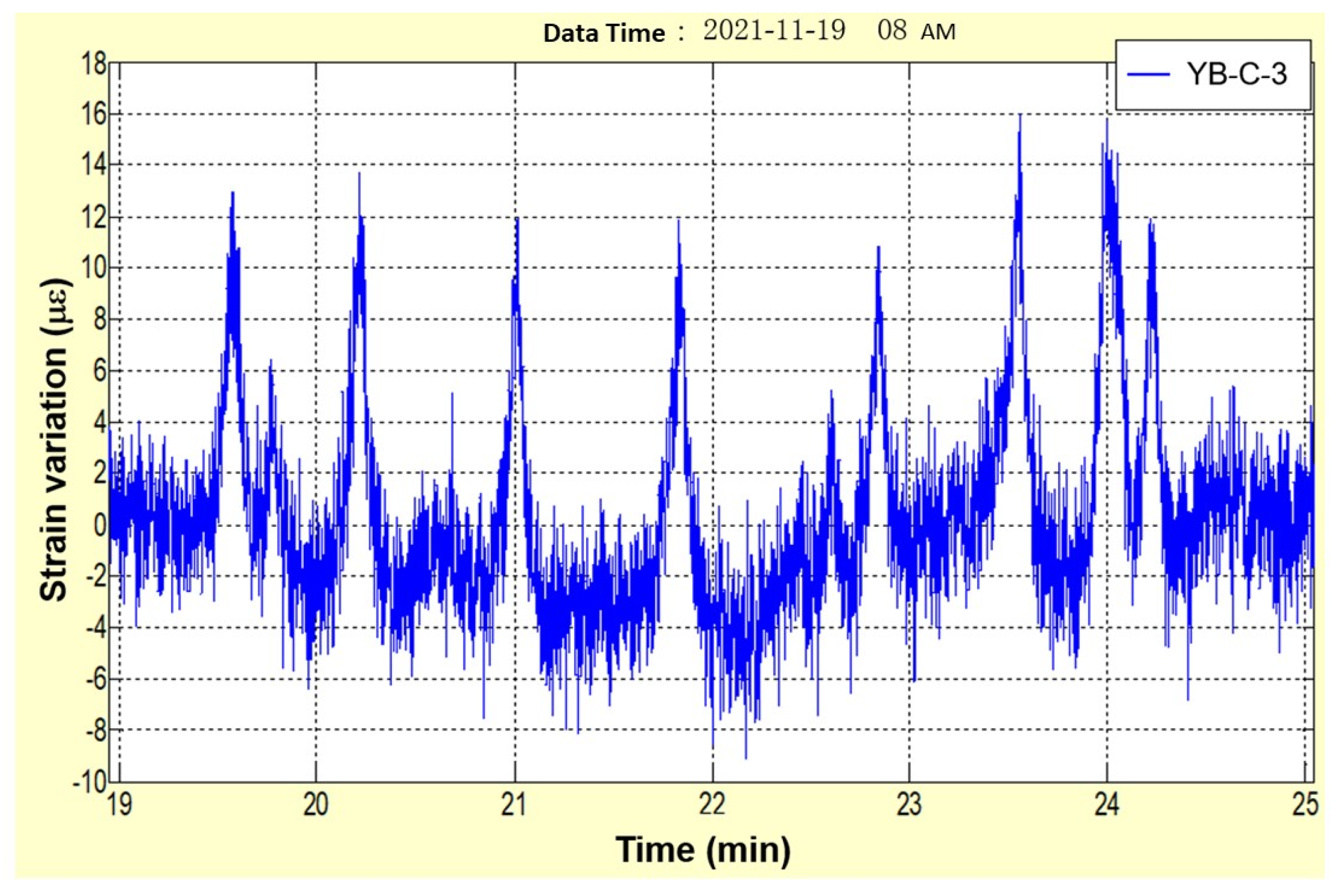
To test the effectiveness of the GFRP-FBG sensor for practical applications, a case study was performed on the Aizhai bridge, Jishou city, Hunan province, China. The Aizhai Bridge is a super long suspension bridge with separated towers and beams and a span arrangement of 242 m + 1176 m + 116 m, as shown in Figure 24. A structural health monitoring system was established to obtain readings for strain, temperature, acceleration, deflection, wind velocity, cable force, and humidity. In this SHM system, four GFRP-FBG sensors were used for strain and temperature measurements on the main beam and main tower. Table 5 lists the technical parameters of the applied GFRP-FBG sensors. The data acquired and processed by the FBG demodulator were transferred to the data receiving server, in which the data could be retained, managed, and arithmetically processed. The GFRP-FBG installed on the Aizhai bridge has been working well since October 2013, and the strain measurements of one of the GFRP-FBGs are demonstrated in Figure 25. This case study highlights that the GFRP-FBG is robust enough for practical application.
5. Conclusions
This study introduced a fabrication method for GFRP-OF sensors and proposed a geometric dimensions determination method for GFRP-OF sensors based on strain transfer theory. A series of tests were carried out to investigate the properties of the GFRP-OF sensors, including their ruggedness, strain, temperature sensing properties, fatigue resistance, and corrosion resistance. The following conclusions were obtained from the study:
- (a)
- The fabrication method for engineering-suitable GFRP-OF sensors was introduced in detail, and the sensor was examined through SEM. According to the SEM images, the interface between bare fiber and GFRP was well combined.
- (b)
- The strain transfer error of the GFRP-OF sensor is determined by the longitudinal shear modulus and radius of the GFRP: a higher GFRP longitudinal shear modulus yields minor strain transfer error, resulting in more accurate measurement, and a smaller GFRP packaging radius introduces minor strain transfer error. Because the shear strength and diameter will affect the robustness of the GFRP-OF, the determination of diameter should seek a balance between strain transfer efficiency and robustness. The strain transfer error is less than 5% for a GFRP-OF sensor with longitudinal shear modulus in the range of 3–9 GPa and diameter in the range of 1–10 mm.
- (c)
- After packaging, the high-strength GFRP dramatically enhanced the robustness of the OF sensors; the shear bearing capacity of GFRP-OF sensors was more than 120 times larger than that of the other three coated OF sensors. The GFRP-FBG and GFRP-DOF had good strain and temperature sensing performance with high linearity, repeatability, and less hysteresis. The GFRP-FBG also exhibited excellent fatigue resistance, with absolute fluctuations of strain sensitivity coefficients within 0.02 pm/με throughout the fatigue cycles, repeatability error that did not exceed 0.5%, and nonlinear errors of less than 2%, as well as good corrosion resistance.
Author Contributions
Conceptualization, methodology, validation, theoretical analysis, writing—original draft preparation, T.J.; investigation, data processing, C.P., W.X. and T.L.; validation, Y.L.; theoretical analysis, writing—review and editing, funding acquisition, H.W.; resources, methodology, supervision, J.H. All authors have read and agreed to the published version of the manuscript.
Funding
This work was financially supported by the National Natural Science Foundation of China under Grant No. 42107210, the Open Research Fund of State Key Laboratory of Geohazard Prevention and Geoenvironment Protection under Grant No. SKLGP2022K022, the National Natural Science Foundation of China under Grant No. 61875027, and also by the National Key R&D Program of China under Grant No. 2019YFC1509602, the National Natural Science Foundation of China under Grant No. 51908263, the National Natural Science Foundation of China under Grant No. DL2021175003L, the National Natural Science Foundation of China under Grant No. G2021175026L.
Institutional Review Board Statement
Not applicable.
Informed Consent Statement
Not applicable.
Data Availability Statement
The data supporting the results reported in the paper can be accessed from the corresponding authors.
Conflicts of Interest
The authors declare no conflict of interest.
References
- Meltz, G.; Morey, W.W.; Glenn, W.H. Formation of Bragg gratings in optical fibers by a transverse holographic method. Opt. Lett. 1989, 14, 823–825. [Google Scholar] [CrossRef] [PubMed]
- Kent, A.M.; Michael, F.G.; Ashish, M.V.; Richard, O.C. Quadrature phase-shifted, extrinsic Fabry-Perot optical fiber sensors. Opt. Lett. 1991, 16, 273–275. [Google Scholar]
- Tateda, M.; Horiguchi, T.; Kurashima, T.; Ishihara, K. First measurement of strain distribution along field-installed optical fibers using Brillouin spectroscopy. J. Lightwave Technol. 1990, 8, 1269–1273. [Google Scholar] [CrossRef]
- Horiguchi, T.; Kurashima, T.; Tateda, M. Tensile strain dependence of Brillouin frequency shift in silica optical fibers. IEEE Photonic Technol. Lett. 1989, 1, 107–108. [Google Scholar] [CrossRef]
- Toshio, K.; Tsuneo, H.; Mitsuhiro, T. Distributed-temperature sensing using stimulated Brillouin scattering in optical silica fibers. Opt. Lett. 1990, 15, 1038–1040. [Google Scholar]
- Kurashima, T.; Tateda, M.; Horiguchi, T.; Koyamada, Y. Performance improvement of a combined OTDR for distributed strain and loss measurement by randomizing the reference light polarization state. IEEE Photonic Technol. Lett. 1997, 9, 360–362. [Google Scholar] [CrossRef]
- Maughan, S.M.; Kee, H.H.; Newson, T.P. 57-km single-ended spontaneous Brillouin-based distributed fiber temperature sensor using microwave coherent detection. Opt. Lett. 2001, 26, 331–333. [Google Scholar] [CrossRef]
- Mizuno, Y.; Zou, W.W.; He, Z.Y.; Hotat, K. Proposal of Brillouin optical correlation-domain reflectometry (BOCDR). Opt. Express 2008, 16, 12148–12153. [Google Scholar] [CrossRef]
- Wang, Y.; Yuan, H.; Liu, X.; Bai, Q.; Zhang, H.; Gao, Y.; Jin, B. A comprehensive study of optical fiber acoustic sensing. IEEE Access 2019, 7, 85821–85837. [Google Scholar] [CrossRef]
- Zhang, S.H.; Liu, B.; He, J.P. Pipeline deformation monitoring using distributed fiber optical sensor. Measurement 2019, 133, 208–213. [Google Scholar] [CrossRef]
- Berrocal, C.G.; Fernandez, I.; Bado, M.F.; Casas, J.R.; Rempling, R. Assessment and visualization of performance indicators of reinforced concrete beams by distributed optical fibre sensing. Struct. Health Monit. 2021, 20, 3309–3326. [Google Scholar] [CrossRef]
- Bao, Y.; Valipour, M.; Meng, W.; Hayat KH, K.; Chen, G. Distributed fiber optic sensor-enhanced detection and prediction of shrinkage-induced delamination of ultra-high-performance concrete overlay. Smart Mater. Struct. 2017, 26, 085009. [Google Scholar] [CrossRef]
- He, J.P.; Xue, Y.; Xu, J.; Zhang, D.Q.; Zhang, S.H. Whole-process monitoring of sinkhole collapse based on distributed optical fiber strain-vibration joint system and its case study in railway subgrade. Opt. Fiber Technol. 2020, 60, 102380. [Google Scholar] [CrossRef]
- Chai, J.; Lei, W.L.; Du, W.G.; Yuan, Q.; Zhu, L.; Zhang, D.D.; Li, H. Experimental study on distributed optical fiber sensing monitoring for ground surface deformation in extra-thick coal seam mining under ultra-thick conglomerate. Opt. Fiber Technol. 2019, 53, 102006. [Google Scholar] [CrossRef]
- Liu, S.P.; Gu, K.; Zhang, C.C.; Shi, B. Experimental research on strain transfer behavior of fiber-optic cable embedded in soil using distributed strain sensing. Int. J. Geomech. 2021, 21, 04021190. [Google Scholar] [CrossRef]
- Zhang, C.C.; Shi, B.; Zhu, H.H.; Wang, B.J.; Wei, G.Q. Toward distributed fiber-optic sensing of subsurface deformation: A theoretical quantification of ground-borehole-cable interaction. J. Geophys. Res.-Solid Earth 2020, 125, e2019JB018878. [Google Scholar] [CrossRef]
- Maraval, D.; Gabet, R.; Jaouen, Y.; Lamour, V. Dynamic optical fiber sensing with Brillouin optical time domain reflectometry: Application to pipeline vibration monitoring. J. Lightwave Technol. 2017, 35, 3296–3302. [Google Scholar] [CrossRef]
- Ren, L.; Li, H.N.; Li, S.; Li, D.S. Development of tube-packaged FBG strain sensor and application in the vibration experiment of submarine pipeline model. In Proceedings of the Advanced Sensor Systems and Applications II, Beijing, China, 8–12 November 2004; Volume 5634. [Google Scholar]
- Madani, A.; Harazim, S.M.; Bolaños Quiñones, V.A.; Kleinert, M.; Finn, A.; Ghareh Naz, E.S.; Ma, L.; Schmidt, O.G. Optical microtube cavities monolithically integrated on photonic chips for optofluidic sensing. Opt. Lett. 2017, 42, 486–489. [Google Scholar] [CrossRef]
- Havermann, D.; Mathew, J.; MacPherson, W.N.; Maier RR, J.; Hand, D.P. Temperature and strain measurements with fiber Bragg gratings embedded in stainless steel 316. J. Lightwave Technol. 2015, 33, 2474–2479. [Google Scholar] [CrossRef]
- Mou, C.B.; Saffari, P.; Li, D.Z.; Zhou, K.M.; Zhang, L.; Soar, R.; Bennion, I. Smart structure sensors based on embedded fibre Bragg grating arrays in aluminium alloy matrix by ultrasonic consolidation. Meas. Sci. Technol. 2009, 20, 034013. [Google Scholar] [CrossRef]
- Tu, Y.; Tu, S.T. Fabrication and characterization of a metal-packaged regenerated fiber Bragg grating strain sensor for structural integrity monitoring of high-temperature components. Smart Mater. Struct. 2014, 23, 035001. [Google Scholar] [CrossRef]
- Ou, J.P.; Zhou, Z. Encapsulation techniques for FBG and smart monitoring for bridges with FBG sensors. In Proceedings of the 4th International Workshop on Structural Health Monitoring at Stanford University, Stanford, CA, USA, 15–17 September 2003; pp. 180–187. [Google Scholar]
- Kuang, Y.; Guo, Y.X.; Xiong, L.; Liu, W.L. Packaging and temperature compensation of fiber Bragg grating for strain sensing: A Survey. Photonic Sens. 2018, 8, 04320. [Google Scholar] [CrossRef] [Green Version]
- Wang, H.P.; Jiang, L.Z.; Xiang, P. Priority design parameters of industrialized optical fiber sensors in civil engineering. Opt. Laser Technol. 2018, 100, 119–128. [Google Scholar] [CrossRef]
- Wang, H.P.; Jiang, L.Z.; Xiang, P. Improving the durability of the optical fiber sensor based on strain transfer analysis. Opt. Laser Technol. 2018, 42, 97–104. [Google Scholar] [CrossRef]
- Ren, P.; Zhou, Z. Low modulus polymer packaged optical fiber sensor for macro-crack monitoring in ice structures of cold regions. Opt. Eng. 2014, 53, 097102. [Google Scholar] [CrossRef]
- Sun, W.; Jia, L.F.; Wang, Z.Y.; Jia, Z.G. Optical fiber sensor encapsulated by polyurethane. Optik 2018, 165, 124–131. [Google Scholar] [CrossRef]
- Sun, Y.; Lee, H.S.; Han, B. Measurement of elastic properties of epoxy molding compound by single cylindrical configuration with embedded fiber Bragg grating sensor. Exp. Mech. 2017, 57, 313–324. [Google Scholar] [CrossRef]
- Leung, C.K.Y.; Wan, K.T.; Inaudi, D.; Inaudi, D.; Bao, X.; Habel, W.; Zhou, Z.; Ou, J.; Ghandehari, M.; Wu, H.C.; et al. Review: Optical fiber sensors for civil engineering applications. Mater. Struct. 2015, 48, 871–906. [Google Scholar] [CrossRef] [Green Version]
- Tang, Y.S.; Wu, Z.S. Distributed long-gauge optical fiber sensors based self-sensing FRP bar for concrete structure. Sensors 2016, 16, 286. [Google Scholar] [CrossRef] [Green Version]
- He, J.P.; Zhou, Z.; Ou, J.P. Optic fiber sensor-based smart bridge cable with functionality of self-sensing. Mech. Syst. Signal Pract. 2013, 35, 84–94. [Google Scholar] [CrossRef]
- Tarawneh, M.A.; Huang, Y. Glass fiber-reinforced polymer packaged fiber Bragg grating sensors for low-speed weigh-in-motion measurements. Opt. Eng. 2016, 55, 086107. [Google Scholar] [CrossRef]
- Dawood, T.A.; Shenoi, R.A.; Sahin, M. A procedure to embed fibre Bragg grating strain sensors into GFRP sandwich structures. Compos. Part A 2007, 38, 217–226. [Google Scholar] [CrossRef]
- Huang, M.H.; Zhou, Z.; Huang, Y.; Ou, J.P. A distributed self-sensing FRP anchor rod with built-in optical fiber sensor. Measurement 2013, 46, 1363–1370. [Google Scholar] [CrossRef]
- Wang, H.P.; Xiang, P.; Jiang, L.Z. Strain transfer theory of industrialized optical fiber-based sensors in civil engineering: A review on measurement accuracy, design and calibration. Sens. Actuators A Phys. 2019, 285, 414–426. [Google Scholar] [CrossRef]
- Vedernikov, A.; Safonov, A.; Tucci, F.; Carlone, P.; Akhatov, I. Pultruded materials and structures: A review. J. Compos. Mater. 2022, 54, 4081–4117. [Google Scholar] [CrossRef]
- Vedernikov, A.; Safonov, A.; Tucci, F.; Carlone, P.; Akhatov, I. Modeling spring-in of L-shaped structural profiles pultruded at different pulling speeds. Polymers 2021, 13, 2748. [Google Scholar] [CrossRef]
- Shao, L.; Ou, J.P.; Zhou, Z. Development of a new anchorage system for carbon fiber–reinforced polymer rods using extrusion process. Adv. Struct. Eng. 2022, 25, 1002–1014. [Google Scholar]
- ACI440.1R-15; Guide for the Design and Construction of Structural Concrete Reinforced with Fiber Reinforced Polymer (FRP) Bars. ACI Committee 440; IHS Group: Farmington Hills, MI, USA, 2015.
- He, J.P. Full-Scale Distributed Monitoring Technology of Optical Fiber Brillouin and its Applications in Civil Engineering. Ph.D. Thesis, Harbin Institute of Technology, Harbin, China, 2009. (In Chinese). [Google Scholar]
Figure 1.
GFRP-OF sensors: (a) schematic drawing; (b) photo.

Figure 2.
Strain transfer analysis model of GFRP-OF sensor.
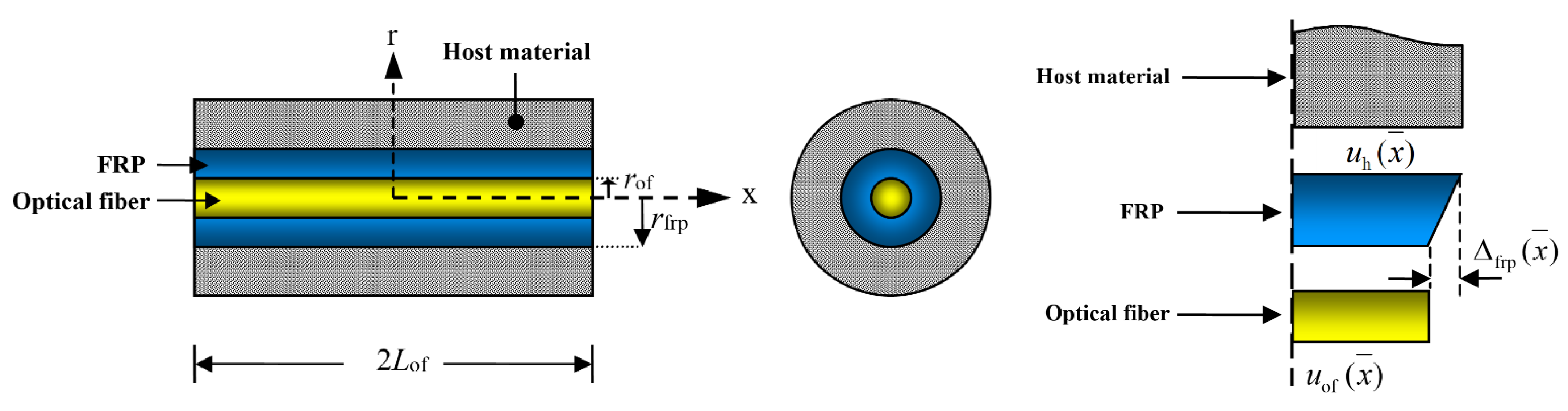
Figure 3.
Influence of GFRP material properties and geometry on strain transfer error: (a) longitudinal shear modulus; (b) radius.
Figure 3.
Influence of GFRP material properties and geometry on strain transfer error: (a) longitudinal shear modulus; (b) radius.

Figure 4.
(a) Schematic packaging procedures for GFRP-OF sensor, and (b) prototype of the GFRP-OF sensor.
Figure 4.
(a) Schematic packaging procedures for GFRP-OF sensor, and (b) prototype of the GFRP-OF sensor.
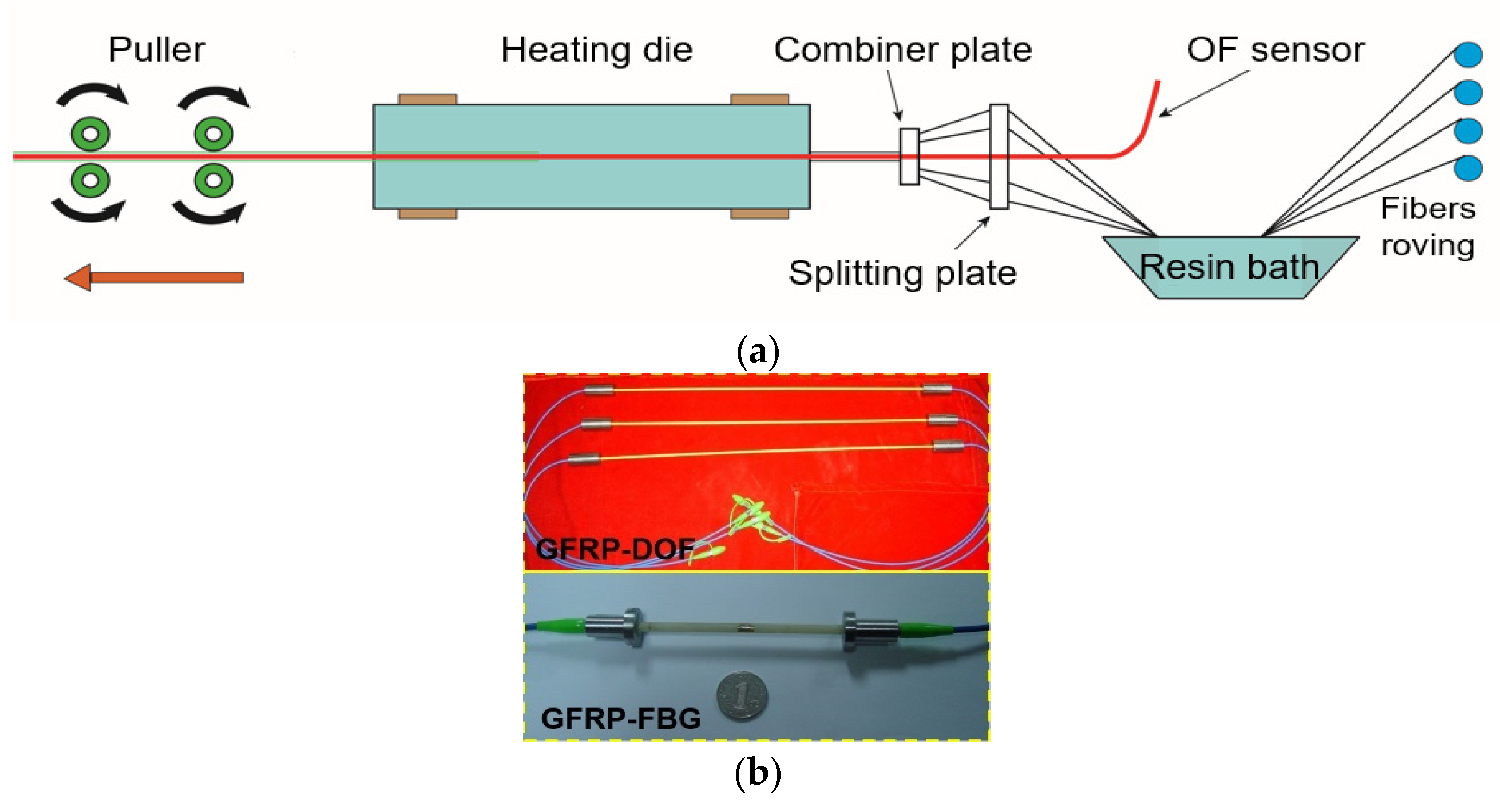
Figure 5.
SEM images of GFRP-OF sensor: (a) at 10,000×; (b) at 20×.
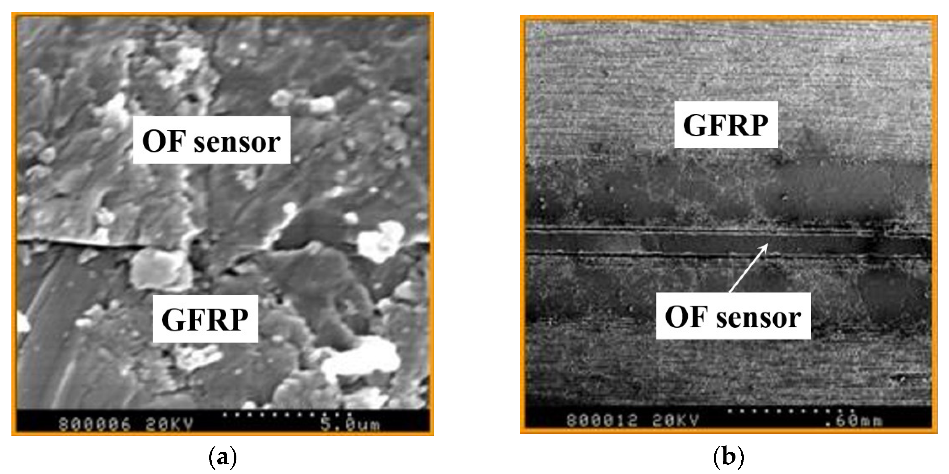
Figure 6.
Experimental setup for shear strength tests: (a) GFRP-OF; (b) other coated OF sensors.

Figure 7.
Experimental setup for ultimate tensile strain tests: (a) GFRP-DOF; (b) coated OF sensor.

Figure 8.
Experimental setup for GFRP-FBG sensor strain sensing test.

Figure 9.
Experimental setup for temperature sensing tests.
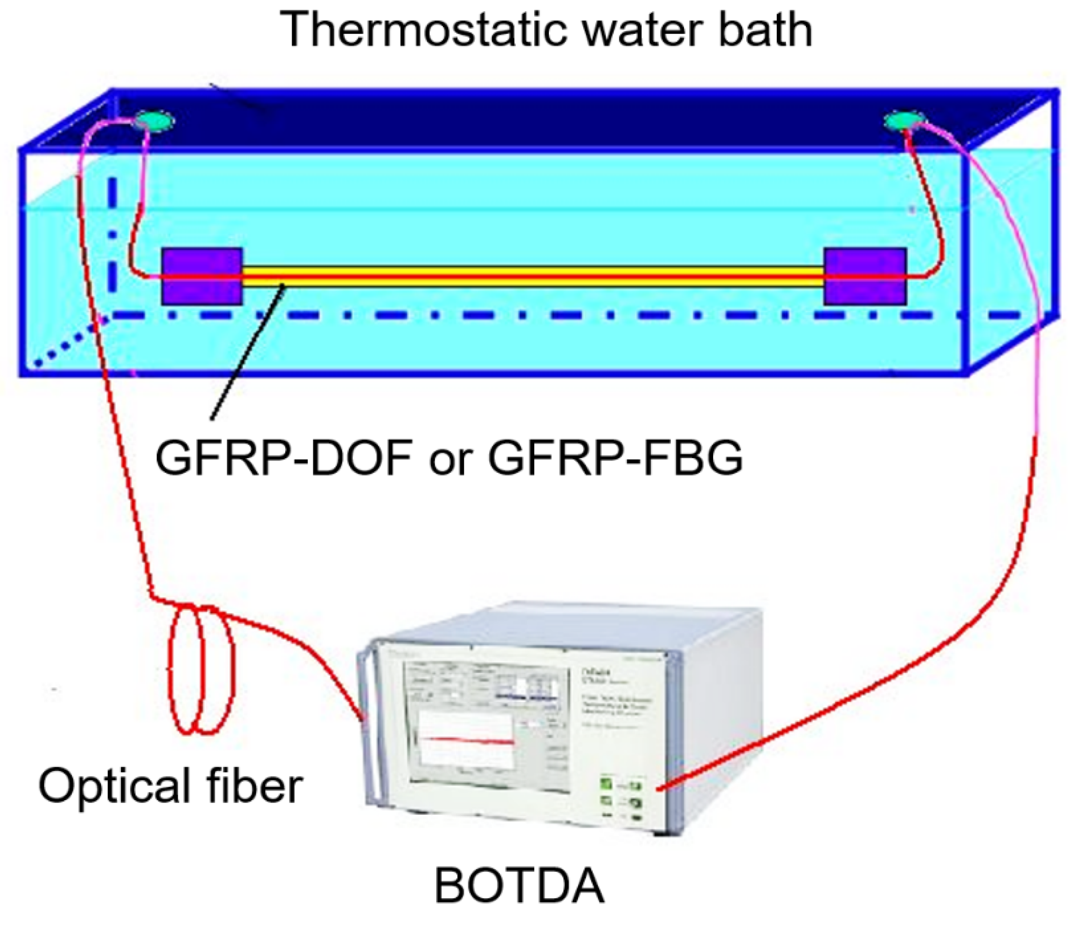
Figure 10.
Experimental setup for fatigue tests.
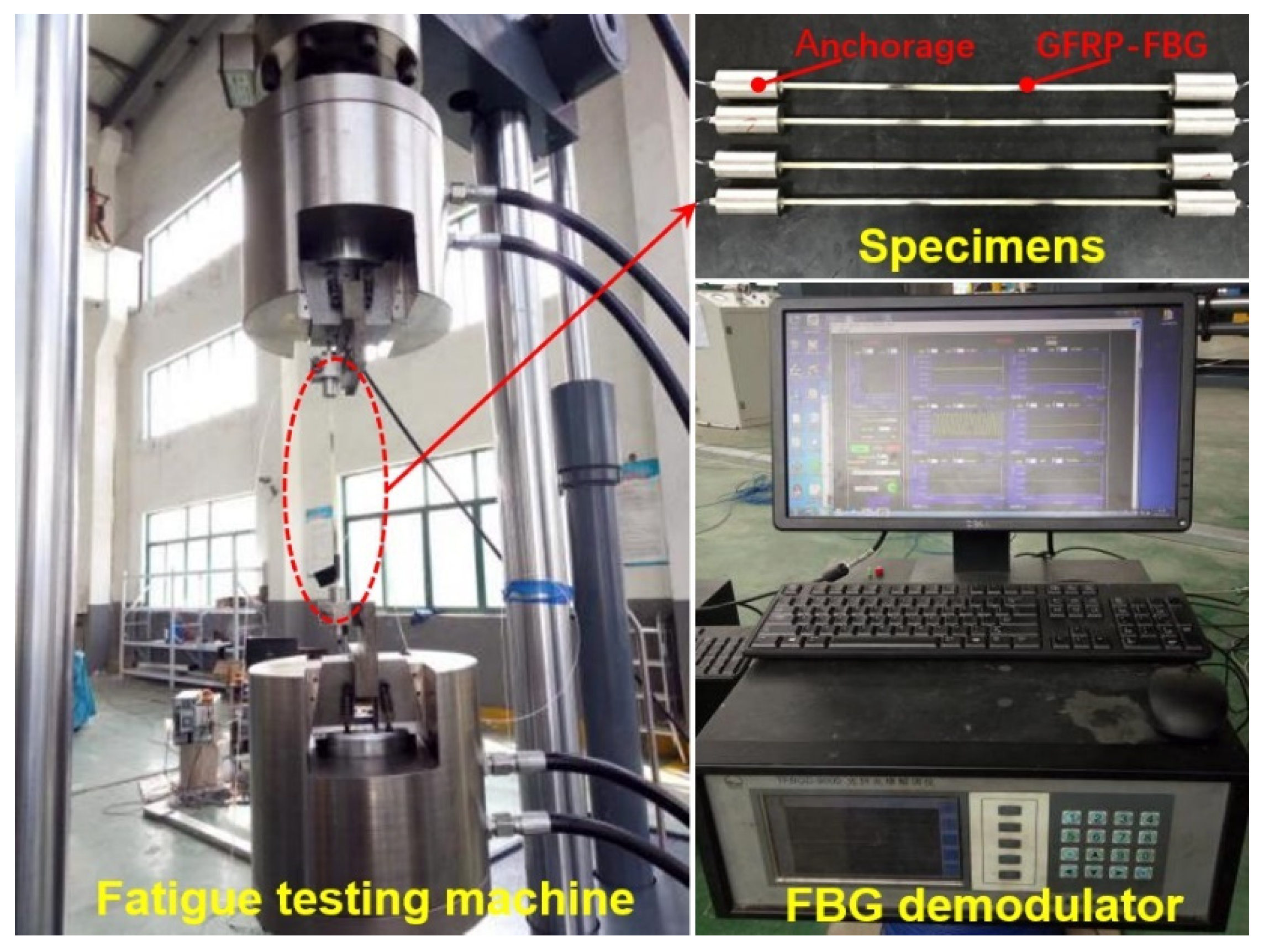
Figure 11.
Anchorage of GFRP-FBG [39].
Figure 11.
Anchorage of GFRP-FBG [39].
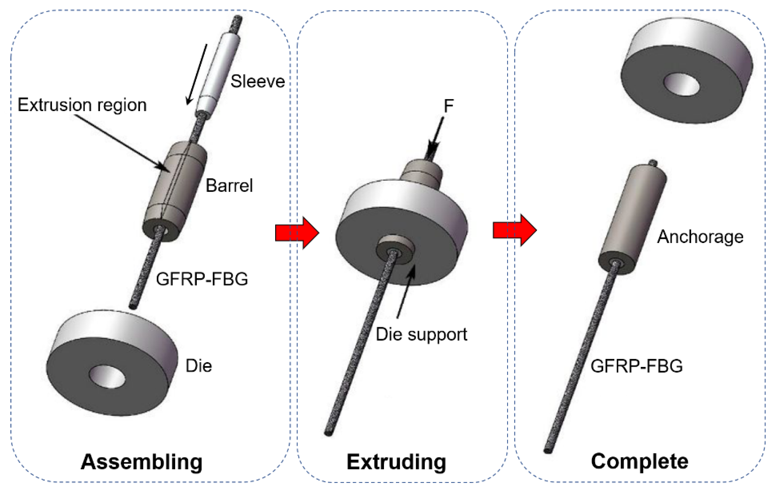
Figure 12.
Experimental setup for corrosion durability tests.
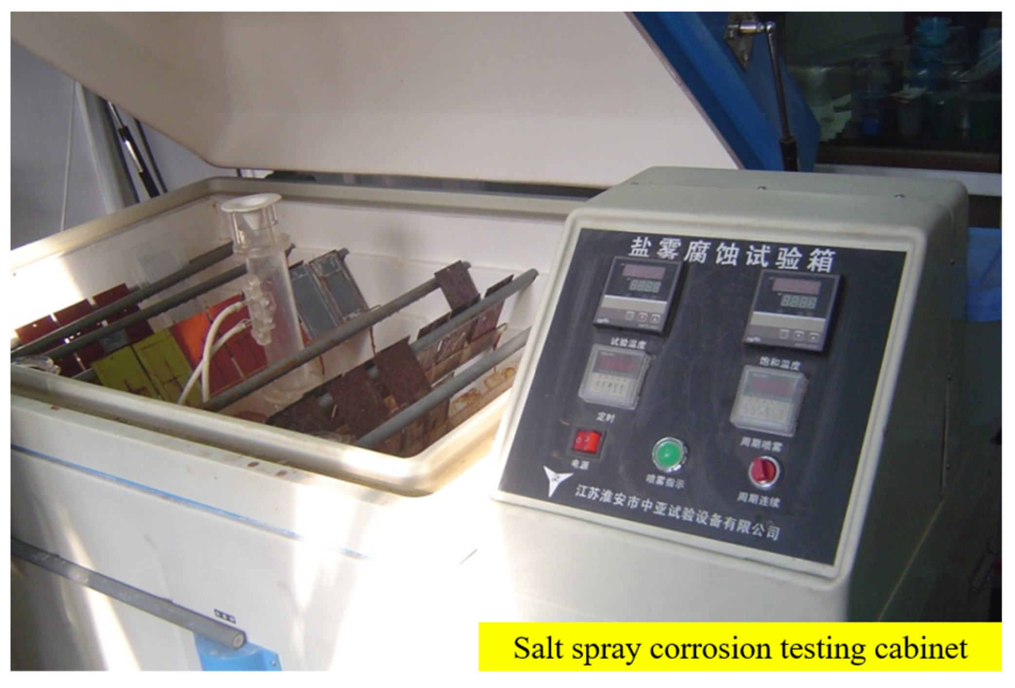
Figure 13.
Results of strain sensing test of GFRP-FBG: (a) sensitivity and (b) loading and unloading.
Figure 13.
Results of strain sensing test of GFRP-FBG: (a) sensitivity and (b) loading and unloading.

Figure 14.
Results of strain sensing test of GFRP-DOF sensor.

Figure 15.
Results of temperature sensing test of GFRP-FBG.
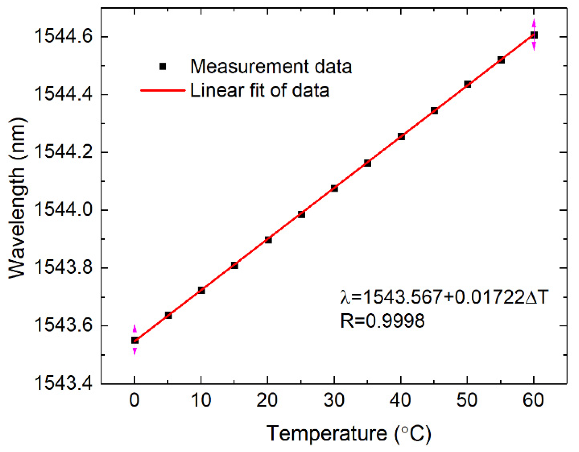
Figure 16.
Results of temperature sensing test of GFRP-DOF.
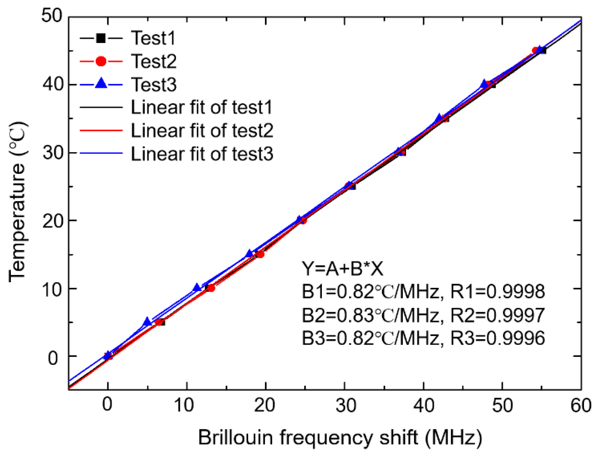
Figure 17.
Center wavelength changes in GFRP-FBG at different fatigue cycles.
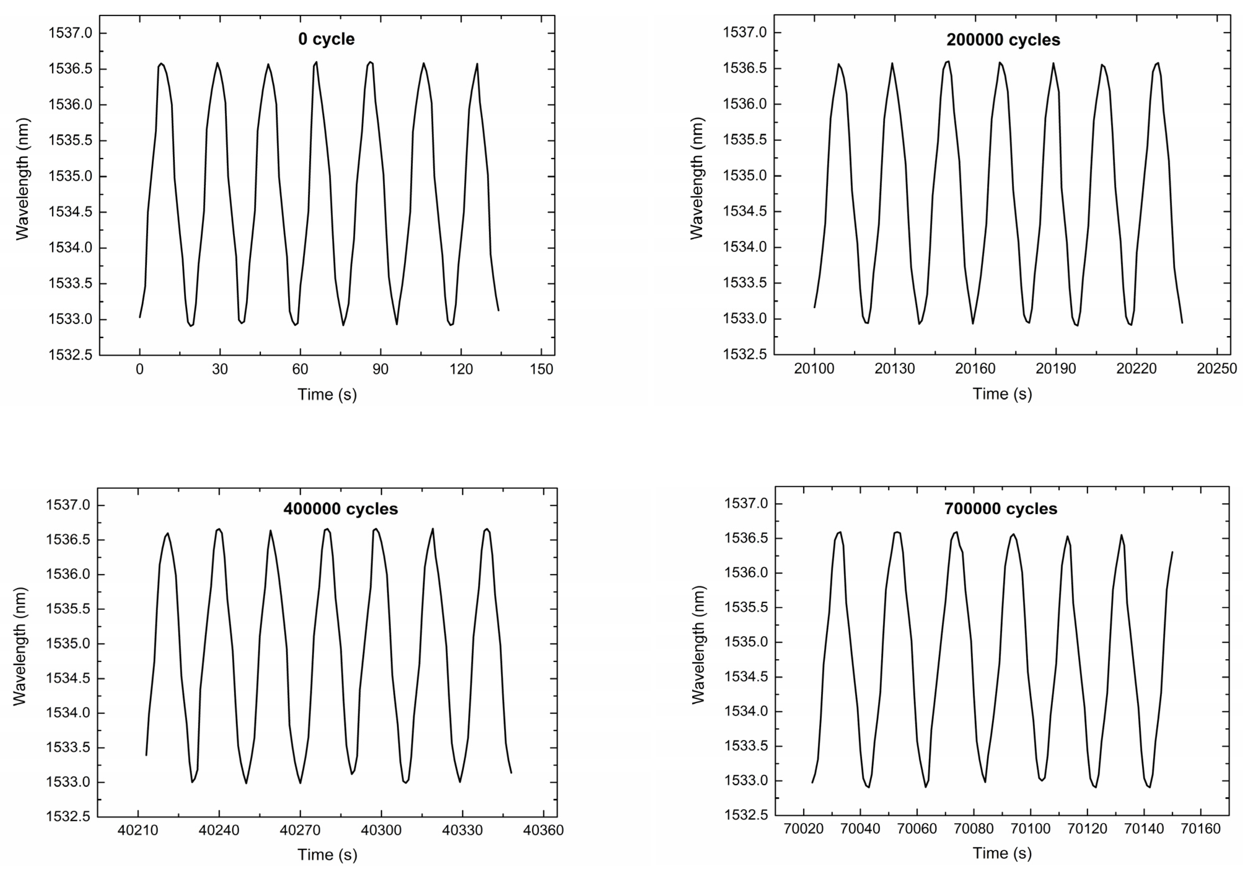
Figure 18.
Relationship between wavelength and strain after different fatigue cycles.

Figure 19.
GFRP-FBG sensitivity coefficient changes after different cycles.

Figure 20.
GFRP-FBG repeatability errors after different cycles.

Figure 21.
Nonlinear errors of GFRP-FBG specimen (F6-1) after different fatigue cycles.
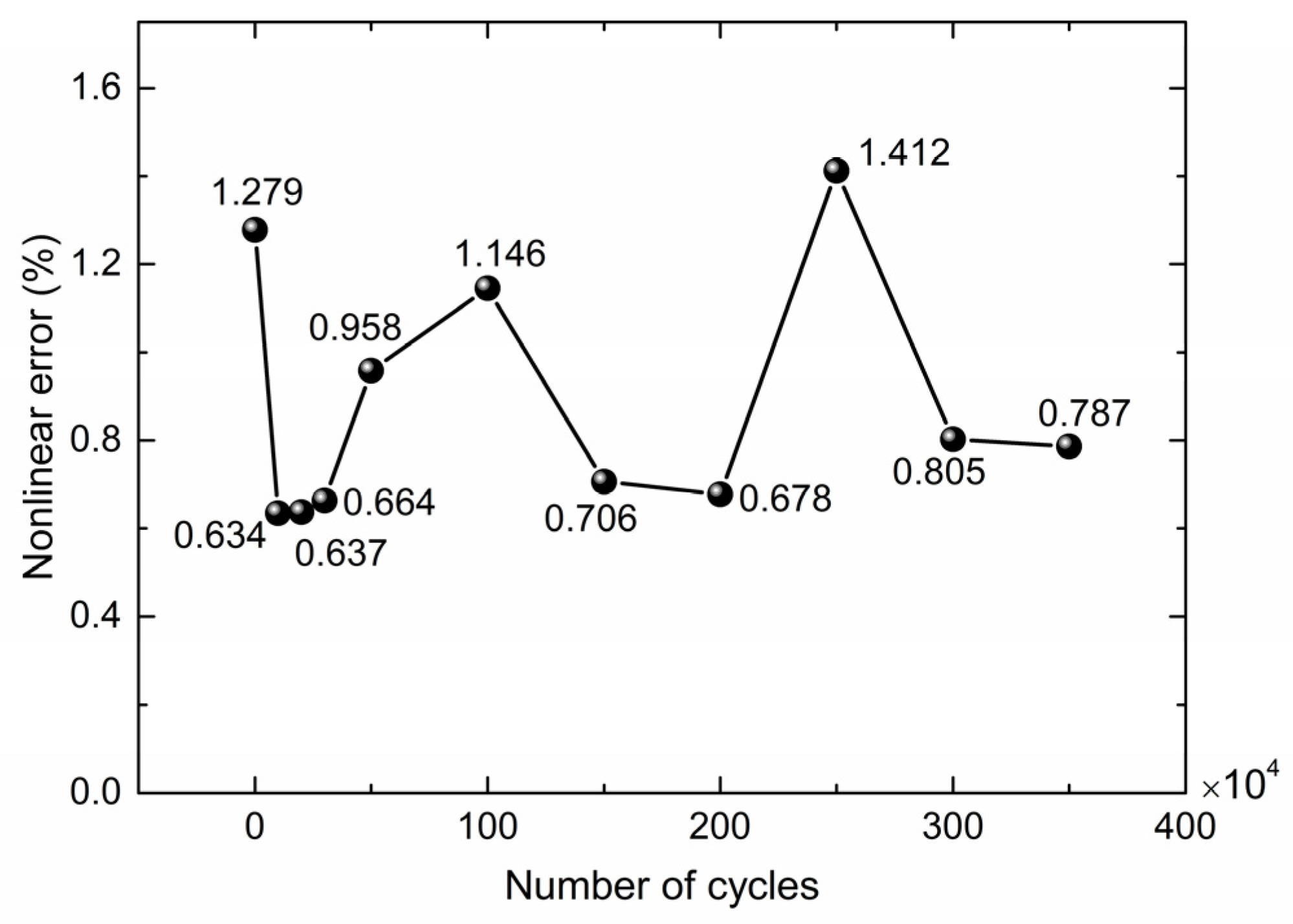
Figure 22.
Strain-fatigue life curve of GFRP-FBG.
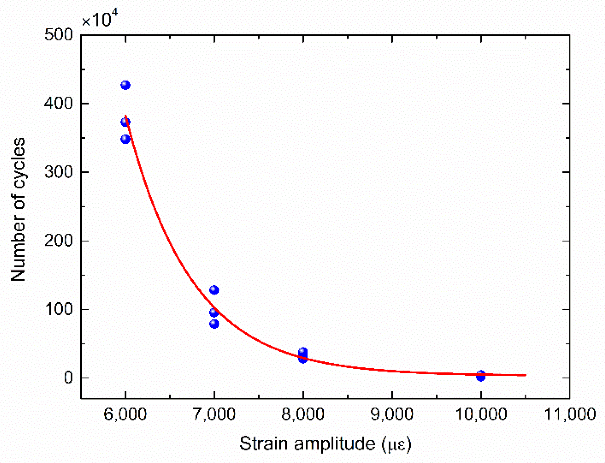
Figure 23.
Results of corrosion durability tests.

Figure 24.
Overview of the Aizhai Bridge.
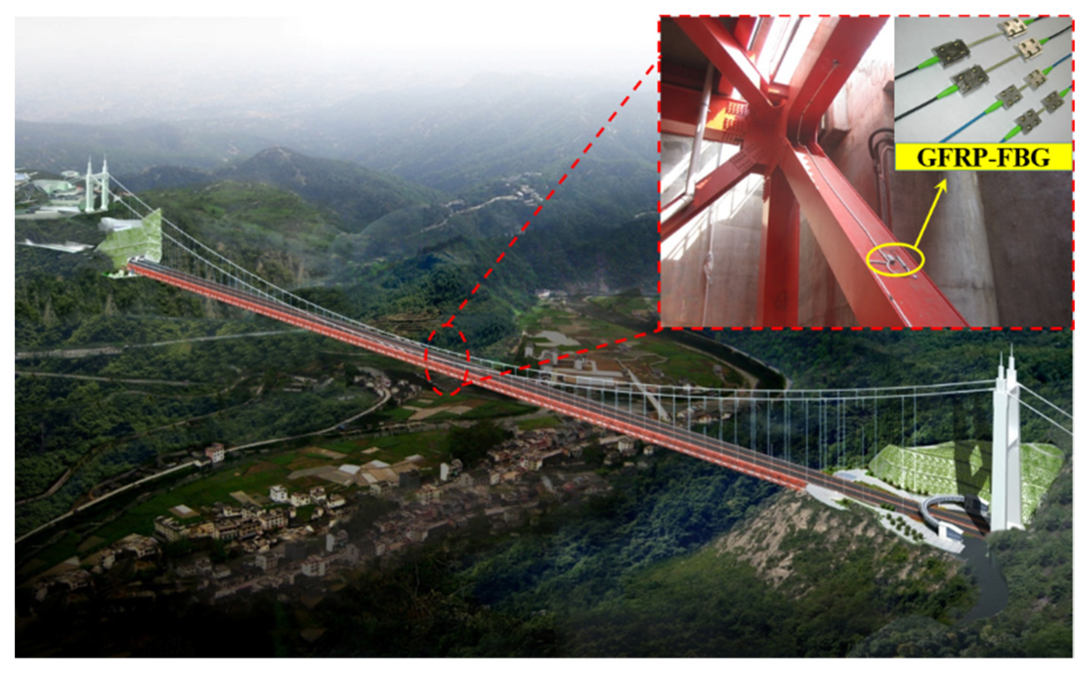
Figure 25.
Strain measurements by GFRP-FBG.

Table 1.
Material and geometrical parameters of the strain transfer model.
| Description | Symbols | Values | Unit |
|---|---|---|---|
| Young’s modulus of optical fiber | 7.2 × 10¹⁰ | Pa | |
| Radius of optical fiber | 6.25 × 10⁻⁵ | m | |
| Longitudinal shear modulus of GFRP | 1 × 10⁹~10 × 109 | Pa | |
| Thickness of GFRP | 0.001~0.01 | m | |
| Half of the gauge length | 0.01 | m |
Table 2.
OF sensors used for ruggedness characterization.
| No | Type of OF Sensor | Coating/Packaging Material | Dia. (mm) | Company |
|---|---|---|---|---|
| 1 | SMF28 bare OF | UV Acrylics | 0.25 | Corning Inc. (New York, NY, USA) |
| 2 | Polyimide-coated OF | Polyimide | 0.17 | T&S Communications LTD (Shenzhen, China) |
| 3 | Carbon-coated OF | Carbon | 0.17 | OFS Fitel, LLC (Norcross, GA, USA) |
| 4 | GFRP-packaged OF | GFRP | 5.00 | Harbin Tide Science & Technology Inc. (Harbin, China) |
Table 3.
Test results for OF with different coating/packaging materials.
| No. | OF Type | Coating/Packaging Materials | Dia. (mm) | Shear Strength (MPa) | Shear Force (N) | Ultra Strain (με) | |||
|---|---|---|---|---|---|---|---|---|---|
| Mean Value | Standard Deviation | Mean Value | Standard Deviation | Mean Value | Standard Deviation | ||||
| 1 | SMF28 bare OF | UV Acrylics | 0.25 | 67.04 | 3.76 | 3.29 | 0.22 | 17,500 | 693 |
| 2 | Polyimide-coated OF | Polyimide | 0.17 | 278.31 | 9.83 | 6.31 | 0.53 | 47,907 | 1919 |
| 3 | Carbon-coated OF | Carbon | 0.17 | 145.12 | 7.22 | 3.29 | 0.16 | 31,939 | 1710 |
| 4 | GFRP-packaged OF | GFRP | 5.00 | 105.00 | 5.03 | 741.83 | 26.21 | 20,375 | 1261 |
Table 4.
Test results under different test conditions.
| Test Conditions | Strain Amplitude (με) | Specimen Number | Fatigue Cycle Number (10,000 Times) | Wavelength Variation (pm) | |
|---|---|---|---|---|---|
| Mean Value | Standard Deviation | ||||
| Fatigue tests with higher cyclic strain | 0~10,000 | F10-1 | 1.9301 | 11 | 0.041 |
| F10-2 | 4.3422 | 9 | 0.038 | ||
| F10-3 | 2.2398 | 9 | 0.029 | ||
| 0~8000 | F8-1 | 33.5210 | 7 | 0.017 | |
| F8-2 | 28.1386 | 10 | 0.033 | ||
| F8-3 | 38.0440 | 8 | 0.031 | ||
| 0~7000 | F7-1 | 78.9963 | 8 | 0.034 | |
| F7-2 | 95.4139 | 9 | 0.029 | ||
| F7-3 | 128.1010 | 6 | 0.027 | ||
| 0~6000 | F6-1 | 372.9284 | 8 | 0.027 | |
| F6-2 | 427.0311 | 3 | 0.009 | ||
| F6-3 | 348.0035 | 7 | 0.019 | ||
| Fatigue tests with lower cyclic strain | 0~2000 | F2-1 | 800 | 5 | 0.013 |
| F2-2 | 800 | 4 | 0.008 | ||
| F2-3 | 800 | 7 | 0.022 | ||
Table 5.
Monitoring items and technical parameters of GFRP-FBG sensors used in case study.
| Object | Monitoring Items | GFRP-FBG Sensors | |||
|---|---|---|---|---|---|
| Frequency | Accuracy | Scale | Numbers | ||
| Main-beam | Steel strain | 20 Hz | 1 με | ±1000 με | 40 |
| Main-beam | Steel temperature | 1 time/h | 0.5 °C | −20 °C~70 °C | 15 |
| Main-tower | Concrete strain | 20 Hz | 1 με | ±1000 με | 8 |
| Main-tower | Concrete temperature | 1 time/h | 0.5 °C | −20 °C~70 °C | 8 |
Publisher’s Note: MDPI stays neutral with regard to jurisdictional claims in published maps and institutional affiliations. |
© 2022 by the authors. Licensee MDPI, Basel, Switzerland. This article is an open access article distributed under the terms and conditions of the Creative Commons Attribution (CC BY) license (https://creativecommons.org/licenses/by/4.0/).
Share and Cite
MDPI and ACS Style
Jiao, T.; Pu, C.; Xing, W.; Lv, T.; Li, Y.; Wang, H.; He, J. Characterization of Engineering-Suitable Optical Fiber Sensors Packaged with Glass Fiber-Reinforced Polymers. Symmetry 2022, 14, 973. https://doi.org/10.3390/sym14050973
AMA Style
Jiao T, Pu C, Xing W, Lv T, Li Y, Wang H, He J. Characterization of Engineering-Suitable Optical Fiber Sensors Packaged with Glass Fiber-Reinforced Polymers. Symmetry. 2022; 14(5):973. https://doi.org/10.3390/sym14050973
Chicago/Turabian StyleJiao, Tong, Chuhong Pu, Wenjing Xing, Tao Lv, Yuan Li, Huaping Wang, and Jianping He. 2022. "Characterization of Engineering-Suitable Optical Fiber Sensors Packaged with Glass Fiber-Reinforced Polymers" Symmetry 14, no. 5: 973. https://doi.org/10.3390/sym14050973
Note that from the first issue of 2016, this journal uses article numbers instead of page numbers. See further details here.