Gravimetric Separation of Heavy Minerals in Sediments and Rocks


Laboratory for Provenance Studies, Department of Earth and Environmental Sciences, University of Milano-Bicocca, Piazza della Scienza 4, 20126 Milan, Italy
Minerals 2020, 10(3), 273; https://doi.org/10.3390/min10030273
Submission received: 15 February 2020
/
Revised: 13 March 2020
/
Accepted: 17 March 2020
/
Published: 18 March 2020
(This article belongs to the Special Issue Heavy Minerals: Methods & Case Histories)
Abstract
:The potential of heavy minerals studies in provenance analysis can be enhanced conspicuously by using a state-of-the-art protocol for sample preparation in the laboratory, which represents the first fundamental step of any geological research. The classical method of gravimetric separation is based on the properties of detrital minerals, principally their grain size and density, and its efficiency depends on the procedure followed and on the technical skills of the operator. Heavy-mineral studies in the past have been traditionally focused on the sand fraction, generally choosing a narrow grain-size window for analysis, an approach that is bound to introduce a serious bias by neglecting a large, and sometimes very large, part of the heavy-mineral spectrum present in the sample. In order to minimize bias, not only the largest possible size range in each sample should be considered, but also, the same quantitative analytical methods should be applied to the largest possible grain-size range occurring in the sediment system down to 5 μm or less, thus including suspended load in rivers, loess deposits, and shallow to deep-marine muds. Wherever the bulk sample cannot be used for practical reasons, we need to routinely analyze the medium silt to medium sand range (15–500 μm) for sand and the fine silt to sand range (5–63 or > 63 μm) for silt. This article is conceived as a practical handbook dedicated specifically to Master and PhD students at the beginning of their heavy-mineral apprenticeship, as to more expert operators from the industry and academy to help improving the quality of heavy-mineral separation for any possible field of application.
“Day by day, what you choose, what you think, and what you do is who you become”Heraclitus
1. Introduction
A detailed and efficient protocol for heavy-mineral separation from sediments and rocks represents a handy practical support tool designed to be consulted routinely in the laboratory. Continuing a tradition started in Italy more than a century ago by De Filippi (1839) [1], who performed a pioneering quantitative provenance study of heavy minerals in sediments of the Ticino River and Artini (1891) [2], who investigated mineralogy of the Po plain sediments, this little handbook will enable Master and PhD students to use it as a substantial help to carry out autonomously a quick and effective heavy-mineral separation, but also, more expert researchers will discover simple practical solutions to speed the separation procedure.
As in Garzanti and Andò (2019) [3], the definition of heavy minerals used in this article includes only minerals of certain extrabasinal terrigenous origin (i.e., ultimately eroded from bedrock exposed in source areas), denser than 2.90 g/cm3, and occurring either as single detrital grains or in rock fragments. Grains of suspect intrabasinal (e.g., carbonates, bioclasts, and glaucony); pedogenic or diagenetic (e.g., aggregates of iron or titanium oxides); and anthropogenic origin (e.g., barite in core samples and moissanite) are thus neglected. Phyllosilicates are neglected as well. Transparent heavy minerals identified under the microscope are considered separately from opaque and altered heavy minerals.
The study of heavy minerals, which was quite popular in the past—for a historical overview, the reader is referred to Carver, 1971 [4] and to the monumental book edited by Mange and Wright, 2007 [5])—has recently seen a renovated and increasing interest also in source-to-sink studies aimed at the search for hydrocarbon reservoirs (e.g., Morton and McGill, 2018 [6]). Laboratory practice for sample treatment and heavy-mineral separation was thoroughly investigated and illustrated a half century ago (e.g., [7,8,9,10]), but, later on, the methodology has seen a sort of standardization, and not only for the best, and the stimulus for the betterment of laboratory procedures has seen little progress since then. An updated recent publication in which the state-of-the art techniques for heavy-mineral separation are thoroughly explained through the entire process, from sampling to mineralogical analysis, thus does not exist to the best of my knowledge. The purpose of this article is to fill this gap, especially as the study of recent unconsolidated silts and sands is concerned. Only a limited attention would be dedicated instead to lithified sandstones, and chemical methods for disaggregation will not be illustrated here. We strongly suggest to minimize the use of chemicals in the lab to a very minimum and especially to avoid the use of carcinogenic organic compounds such as bromoform, which has represented for a century the standard dense liquid used in mineral separation and which is still unfortunately in use in several laboratories worldwide. Other standard procedures include chemical attack with oxalic, acetic, or even chloridric acids, but such attacks are in most cases not only scarcely helpful but also counterproductive. Besides incremental time and cost, every additional passage involves material loss during cleaning, precipitation of insoluble salts, and even loss of key provenance indicators such as olivine or apatite. Another critical aspect that we emphasize here is first and foremost the necessary care taken in the field to collect pristine samples following criteria apt to guarantee both consistency and representativeness.
2. Sampling
No study can be better than the samples collected in the field. Great attention should thus be dedicated to the sampling plan, concerning locations, sampling spacing, and representativity of the targeted sedimentary system [3]. In the case of modern sediments, it is vital to avoid the detrimental practice of panning, which concentrates the densest species and consequently modifies irreparably the original proportions among different detrital minerals.
Once the sample is collected it is important to adopt a good systematic practice in sample labelling, in order to simplify laboratory procedures and avoid bad mistakes. For instance, in the case of modern sediment samples, we simply label them in progressive numerical order specifying the name of a nearby site and, in case of fluvial sediments, the name of the river.
During the successive steps of laboratory protocol, it is wise to add a series of simple coded symbols to readily identify the separated grain-size or density fraction (e.g., 15–500 μm, L = light, <2.90 g/cm3 and H = heavy, >2.90 g/cm3). Color-coded dots can be used to designate sediment fractions separated for specific petrographic, mineralogical, or geochemical analyses.
3. Safety Rules and Pre-treatments
This section illustrates the practical duties that need to be carried out before starting to process a series of sediment samples. Specific care should be dedicated to health and safety issues following good practices in the lab and especially avoiding wherever possible the use of toxic chemicals. The laboratory for mineral separation should be clean, safe, and well-organized. The use of blotting paper before starting any procedure is advisable. Reading carefully safety data sheets for each chemical product used (e.g., acids, dense liquids, etc.) is essential.
NB: Never ever use bromoform. This organic liquid is toxic and carcinogenic!
3.1. Preparation of Na-Polytungstate
Sodium-polytungstate (SPT; salt formula Na6 (H2W12O40)·H2O) is a more suitable heavy liquid, perfectly soluble in water and widely used for heavy-mineral separations. The use of SPT [11] combined with the centrifuge [12,13] has replaced the traditional but very dangerous use of bromoform, also using a much smaller amount of dense liquid and thus saving both costs and time during the procedure. Solutions with density up to 3.15 g/cm3 can be prepared with SPT, which may be helpful to concentrate mineral of interest for geochronological and thermochronological analysis (see Section 6.2 below). Lower densities can be simply achieved by adding deionized or distilled water and higher densities by evaporation in a fume hood. This versatility allows us to separate isodensimetric fractions to concentrate specific minerals (e.g., quartz or K-feldspar for cosmonuclide or optically stimulated luminescence analysis; [14]).
One liter of solution with density 2.90 g/cm3 is obtained from 2420 g of SPT and 478 g of deionized or distilled water poured in a 5-L beaker. Add the SPT in progressive steps, a few grams at a time. Put the beaker on a magnetic stirrer with an anchor for an hour until a homogeneous solution, transparent and pale yellow in color, is obtained. Stop the stirrer and check the density with a lead densimeter with density range 2.50–3.00 g/cm3, in a cylinder with a 4-cm diameter, adding 250 mL of SPT solution.
3.2. Preparation of Na–Dithionite–Citrate–Bicarbonate
The presence of iron oxides and hydroxides (e.g., hematite, lepidocrocite, and goethite) as coatings on single minerals or rock fragments may modify their density and hamper their proper identification under the microscope. This problem needs to be faced while studying surficial textures of weathered minerals in deeply weathered tropical and equatorial soils and paleosols. As a most effective way for iron-oxide removal from clays, the use of Na–Dithionite–Citrate–Bicarbonate (DCB) was proposed by Mehra and Jackson (1958) [15]. This mildly acid solution does not corrode apatite, monazite, or olivine and can thus be used for treatment of sedimentary samples.
The following protocol, derived from procedures used at the Natural History Museum of Milano, is recommended. Take a 5-L beaker with 2 L of deionized water and put the beaker on a magnetic stirrer at maximum speed. Add 120 g of Na-citrate, 40 g of Na-ditionite, and 16 g of Na-bicarbonate. After ca 15 min, when salts are all in solution, the DCB is ready. The DCB is poured in a 500-mL labeled beaker containing the sediment until the sediment is submerged; the rest can be stored for future use. Place the beaker under a fume hood and let the reaction to go on for 12 h at least at room temperature; after which, the sampled is cleaned with abundant (1–2 L) tap water to eliminate acid residues and finally wash with deionized water. This procedure can be used also on rock samples and large crystals and is most effective if followed by energic cleaning with universal degreaser and a brush.
3.3. Preparation of Nylon Sieves with 5 μm and 15 μm Mesh
Steel sieves, which can be cleaned in ultrasonic bath, are commercially available in the market down to 32 (or 20) μm. Since in sediments deposited by tractive currents the finest tail of the size distribution is markedly enriched in ultra-dense minerals (e.g., monazite, magnetite, and zircon; [16]), in very-coarse silt to very-fine sand samples, it is crucial to consider the finest size classes of the sample as well in order not to obtain a biased heavy-mineral suite [17,18]. This holds true also for poorly sorted sediments and especially for cohesive muds and mudrocks, for which including even classes as fine as 5–15 μm is compulsory. For this purpose, specific tools must be prepared.
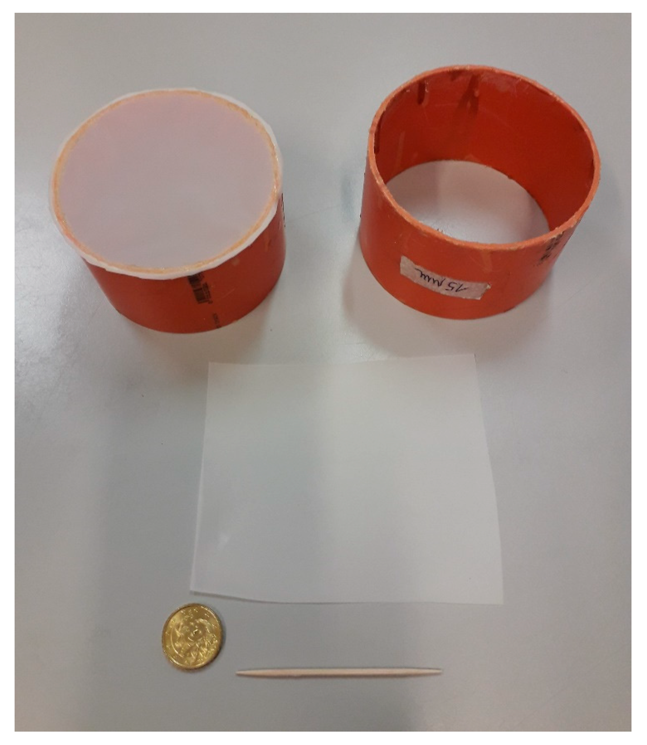
Currently, in our lab, we use handmade tissue sieves with 15 μm, 10 μm, and 5 μm mesh. Nylon mesh rolls that are commercially available are cut in 10-cm-wide strips and then cut in turn in 10 × 10-cm-square pieces that are stored in a clean plastic bag on which the mesh size is clearly indicated. A one-square-piece is mounted on a PVC or plexiglass ring with a diameter of 8 cm obtained by cutting a PVC or plexiglass gutter pipe in 10-cm-high pieces. Both basal and top surfaces of the ring must be made flat and smooth by using sandpaper and then carefully washed.
The tissue sieve is glued well-centered on the surface of the ring using a nontoxic and nonrapid glue spread thinly and evenly all around the rim of the ring. Next, to seal the tissue sieve, a few drops of glue are spread all around the rim with a toothpick, and the handmade tool is dried in a clean oven at ca. 40 °C for several hours. Finally, the tissue in excess is cut with scissors (Figure 1).
NB: Carefully wash the PVC ring with tap water to eliminate residues of abrasive grains used in sandpaper (e.g., moissanite but sometimes also garnet) that may contaminate the heavy-mineral fraction.
3.4. Sample Drying
The sample may reach the lab in diverse conditions and packages. In case of loose sediment, in order to reduce loss or contamination risks the sample is best laid on a large sheet of clean paper. If the sample is wet, then it may be placed in an aluminum tray and left overnight in the oven at a temperature not exceeding 40–60 °C.
4. Let Us Start!
4.1. Rock and Consolidated Samples
The initial laboratory procedures depend on sample type. In the case of hard rocks, the first step is to mechanically disaggregate the sample minimizing pulverization. Rocks are split with a manual or hydraulic press in small centimetric chips (Figure 2). Between 20 and 40 g are generally sufficient to obtain the desired amount of heavy minerals, and the rest of the chips can be archived. The part of the sample collected in a tray is weighed and placed in an agate mortar with 10–20 mL of deionized water to prevent loss of material and the production of powder, which is harmful to breathe. A pressure is exerted repetitively with the agate pestle, avoiding rotational movements that may lead to grain grinding. Gentle percussions have been experimentally demonstrated to cause negligible breakage of heavy minerals (Henningsen, 1967 [19] and Mange and Maurer, 1992 [20] (p. 11)).
In the case of indurated silt or sand, it may suffice to place the weighed sample in a glass beaker, to add 100 mL of deionized water and to stir for several minutes with a metal spatula until complete disaggregation. The obtained sediment suspension can be poured onto the 500-μm mesh sieve as illustrated in Section 5.1 below.
4.2. Micro-Sampling of Loose Sediment
The representativity of the sample is granted not only by careful collection in the field but in the laboratory as well, by following suitable procedures that largely depend on sample grain size. In the simplest case of clean sand, the sample can be split repeatedly in two parts by means of a riffle box (Figure 3). The operation is repeated until the desired amount is obtained, weighed, and placed in a suitable labeled plastic vial. The discarded quantity is archived in the original container. More complex is the case of muddy samples, which are dried, placed on a clean sheet of paper, and well-homogenized horizontally by rolling the paper until a cone of sediment is obtained. Following Parfenoff, 1970 [21] (pp. 45–47), the cone is divided into four parts; a quarter of it is taken, and the rest is stored. The procedure is repeated until an appropriate quantity is obtained and transferred with a suitable tool (Even a bus ticket would do, but do not use electrostatic plastic!) on another clean sheet of paper and weighed. The same Parfenoff method is used in the case of gravelly sand.
4.3. How Much Do We Need?
The amount of sample needed for heavy-mineral separation depends on several factors, including expected heavy-mineral concentration, grain size, sorting, and type of study. Heavy-mineral concentration ranges widely from typically << 1% in case of ancient sandstone or quartzose modern sand heavily weathered in equatorial environments or recycled from ancient quartzarenites (e.g., [22]) to 5%–10% in modern orogenic sediments, reaching up to >50% in placer sands (e.g., [23]).
NB: For modern sands, heavy-mineral concentration can be expeditiously assessed by weighing a well-filled plastic vial of known volume.
As a general standard, we use up to 50–60 g of very coarse sand and 30–40 g of coarse sand, whereas 5–15 g are sufficient for medium sand, 2–3 g for fine to very fine sand, and even only 1 g for silt. For clayey silt and silty clay, it is advisable to take about 5 g.
A semi-quantitative operational approach can be assisted by a simple formula that takes into account not only grain size but also the age of the sample (a rough proxy of the intensity of selective diagenetic dissolution), the average density of expected source rocks, and the degree of heavy-mineral enrichment (as judged empirically by sample color and weight). The required amount of sample X is thus given by: X = t ∙ ρR ∙ S ∙ H, where t ranges between 1 for Holocene samples to 10 for Mesozoic or older samples; ρR ranges between 1 for medium/high-grade source rocks to 10 for sedimentary source rocks; S is 0.5 for silt; 1 is for fine sand, 2 for medium sand, 3 for coarse sand, 10 for very coarse sand, and 30 for pebbly sand; and H ranges between 0.5 for blackish-reddish placer lags to 5 for white antiplacer sand.
NB: Playing with examples:
Silt from a collision orogen unaffected by hydraulic sorting: t = 1, ρR = 2, S = 0.5, and H = 1→ X = 1g
Modern sand from granitoid rocks: t = 1, ρR = 6, S = 2, and H = 4→ X = 48g
Gravelly sand from a magmatic arc: t = 1, ρR = 2, S = 30, and H = 1→ X = 60g
Mesozoic fine-grained sandstone from a cratonic basement: t = 10, ρR = 10, S = 1, and H = 1→ X = 100g
4.4. Do We Really Need Large Samples for U-Pb Zircon Dating?
In the last decade, detrital-zircon geochronology has become one of the most popular approach to provenance analysis. In order to be sure to extract a sufficient amount of zircon grains and to minimize logistic problems and costs, researchers may think of preconcentrating heavy minerals in the field with expeditious techniques such as panning. Panning, however, concentrates denser grains at the expense of less dense grains and therefore introduces bias, for instance because metamictic zircon is less dense than crystalline zircon (e.g., [24]). Is the only correct alternative to collect very big samples (many kilograms; e.g., [25])?
Considering the hydraulic-equivalence principle that tells us that zircon grains in water-laid fine to medium sand are a 0.6–0.7ϕ class finer than the bulk sample [16,26], the appropriate grain size of the sample to be collected is assessed readily and even precisely by taking advantage of ad hoc software [27]. The volume of sand that needs to be collected in the field may thus be reduced by orders of magnitude. By adopting a correct protocol in the lab, that may be applied even for coarse silt, even small sediment samples (2–10 g) can yield a sufficient amount of datable zircon grains. In this way, a series of problems are circumvented, not only as regards field logistics and shipping costs, but also, mineral separation in the laboratory becomes more rapid and much less cumbersome. This is particularly valuable when only a few grams of material are available (e.g., deep-sea cores).
After following the procedure illustrated here below, without doing any further preconcentration by toxic liquids such as methylene iodide, or by Wilfley table, Franz magnetometer, or hand-picking that inevitably introduce a grain-selection bias, the heavy-mineral separate is mounted in araldite, and each grain in the mount is located and identified by Cartesian coordinates under either the Raman spectroscope or the scanning electron microscope [28]. Fixing scanning electron microscope grids or other easily identified locator grids to the mount is useful and offers a simple solution for identifying the exact position of points of interest within a sample, where grains can then be located by reference to these.
5. Sieving Procedures
NB: The worst mistakes that may occur in the lab are accidental sample switch or sample contamination. To stay on the safe side, samples are best processed in numerical order. In case of a modern fluvial system, you may proceed from upstream to downstream.
5.1. Wet Sieving with Steel Sieves
Sediment samples may contain a mixture of clay, silt, sand, and gravel and thus need to be sieved before heavy-mineral separation. In poorly sorted sediments, the presence of detrital grains with great size differences within a single concentrate makes mounting and identification difficult [20]. For these reasons, we routinely consider a size window as large as possible, including as many as 5ϕ classes (15–500 μm; see [3] for a detailed discussion of this crucial issue).
Wet sieving is particularly recommended for poorly sorted sediments including mud. The weighted aliquot of the original sample is placed in a glass beaker with 100 mL of deionized water to facilitate disaggregation of particles. For recent sediments, a gentle pressure with a spatula or spoon will be enough. In order to extract heavy minerals from the 15–500-μm-size window, then a 500-μm sieve is cleaned and mounted onto a sieve bottom pan with drainage outlet. This is useful to collect in another beaker the passing < 500-μm sediment suspension.
NB: During this process, dense minerals may concentrate and remain in the sieve bottom pan. The bias introduced by an inaccurate recovery from the beaker may be serious, especially for heavy-mineral poor samples and for the densest heavy minerals (Figure 4).
In order to recover the entire amount of the <500-μm fraction, the sieve bottom pan must be cleaned several times with tap water until no grains are detected on the sieve bottom pan.
NB: Since we choose to avoid chemical attack with hydrogen peroxide, samples very rich in plant debris pose a problem; their mechanical comminution during sieving produces a flux of particles that pass through the steel meshes. The weight of the passing fraction is thus somewhat overestimated and the heavy-mineral concentration slightly underestimated. Repeated washing beyond 3–5 times is therefore not recommended.
The <500-μm sediment suspension is left to settle in the beaker overnight. After sand and silt have settled, most of the water is siphoned off with a little tube, taking advantage of the principle of communicating vessels. Some water is left in the beaker for the subsequent sieving step.
NB: Sediment in suspension can be recovered from the beaker for further investigations of clay mineralogy and chemistry or organic matter.
5.2. Wet Sieving with Nylon Sieves
A handmade sieve with 15-μm, 10-μm or 5-μm mesh (prepared as in Section 3.3) is labeled by writing the sample name and grain-size range (e.g., 15–500 μm) on adhesive paper. The sieve is placed in a funnel sustained by a metal rack, centered above a 2l beaker labeled by writing the sample name and grain-size range (e.g., <15 μm) on adhesive paper. A supplementary beaker is prepared in the same way. A little water and sediment are poured in the sieve, exerting a gentle pressure with fingers using gloves.
NB: A light pressure and continuous stirring are necessary to speed up the sieving process and avoid that the clay is deposited, thus clogging the meshes. Excess pressure, however, can break the nylon sieve.
The process needs to be repeated over and over, adding a small quantity of sediment each time to avoid clogging of the meshes. After each step, the sieve is placed in the empty supplementary beaker and moved up and down to let the water pass through and clean the net.
NB: The use of ultrasonic bath is not recommended, as it might lead to the deformation of nylon meshes, thus jeopardizing the quality of the sieving process.
At the end of this multistep procedure, which may take between tens of minutes to several hours, the cleaned 15–500-μm-class thus obtained is transferred into a labeled paper filter and dried in an oven overnight at 40–60 °C. The tissue is then removed with a knife from the handmade sieve and disposed.
The passing <15-μm fraction collected in the beaker is left to settle for up to a full day. Once settled, the excess water is siphoned off. The sediment is transferred in a smaller beaker (e.g., 500 mL) by pipetting deionized water and left again to settle. The day after, the excess water is siphoned off, and the small beaker with sediment is placed in the oven. Once dried, the <15-μm fraction is weighed and archived.
NB: While recovering sediment from the paper filter, be careful and avoid exerting an excessive pressure with your fingers that may generate paper fibers in the sample. In this event, the fibers can be easily removed with an electrostatically charged tip. Successively, whenever the sediment is poured on paper for weighing or splitting, the use of transparent paper is recommended to avoid undesired electrostatic effects and material loss which may be significant for silt samples and platy minerals.
Since this procedure takes three days, it is convenient to process batches of 4–5 samples and possibly to work in pairs to optimize efficiency.
5.3. Clay-rich Samples: Settling Tubes and Wet Sieving at 5 μm
Clay-rich samples cannot be processed by wet-sieving alone in a reasonable amount of time, because the nylon meshes are quickly clogged. In these cases, a hybrid procedure is recommended to extract the silt fraction, which may be essential in heavy-mineral studies of soils, suspended load, eolian dust, lagoonal or offshore muds, or deep-sea turbidites [29,30,31,32,33,34].
The weighted sample is passed through a 63-μm steel sieve mounted onto a sieve bottom pan with drainage outlet. Sand-size grains, commonly including micas, bioclasts or plant debris, are thus separated and weighed. The passing <63-μm fraction, collected in a glass beaker, is poured in a 40-cm-high graduated cylinder with a 6-cm diameter and 1000-mL volume filled up with filtered tap water. After adding 1 g of sodium hexaphosphate, the suspension is homogenized for 1 min with a 55-cm-high PVC or steel stirrer with a 5-cm diameter, thus preventing flocculation. After 20 min, silt particles are settled, and the dirty water in excess of 100 mL containing clay (<2 μm fraction) is siphoned off and left in a 5-L beaker for days. It is recommended to siphon water off up to the 100 mL line of the cylinder in order to avoid siphoning off any silt. The procedure is repeated up to five times, adding filtered tap water and Na-hexaphosphate each time.
The silt fraction thus obtained is carefully pipetted out of the cylinder in a glass beaker and next wet-sieved with handmade sieves at 5 μm following the procedure illustrated in Section 5.2. The cleaned silt fraction (5–63 μm) thus obtained is dried in an oven at 40–60 °C and weighed. The passing (<5 μm) very fine silt class is left to settle in the beaker. Heavy minerals can be separated from very fine silt, but they are too small to be recovered with paper filter. The clay fraction can be also recovered and weighed.
6. Gravimetric Separation by Centrifugation
The use of the centrifuge has become a most practical method of heavy-mineral separation since the development of the partial freezing method [4,20]. Nevertheless, the use of funnels is still largely adopted, even though it involves larger volumes of the dense liquid, longer times for recovery, low replicability of results because of operator bias, and lower quality of the heavy-mineral separation. Moreover, the funnel method is strongly discouraged for silt-sized sediments for a variety of reasons. The use of the centrifuge with 50-mL conic test tubes combined with partial freezing in liquid nitrogen represents a better procedure by far, allowing us to obtain a very sharp separation of heavy minerals from tectosilicates and other low-density particles that are common in sediments.
NB: The conic tubes must have externally printed graduation; otherwise, grains may be trapped by the internal graduation steps.
6.1. Ordinary Separation with SPT at 2.90 g/cm3
Once dried, the sieved grain-size fraction is ready for gravimetric separation with sodium politungstate (SPT) at density 2.90 g/cm3. If a common centrifuge with four positions is used, then it is convenient to treat four samples at a time. Each conic tube is labeled with the sample name written both on the lid and on the sides. One by one, the sediment samples are poured in the appropriate test tube, which is inserted in a holder placed on a large piece of a thoroughly cleaned paper. The tubes are progressively stored in a plastic tube rack possibly orderly in increasing numerical order. Next, a tube holder is placed on a precision balance and, shifting the tare to zero, each test tube is weighed, adding SPT to the sediment until the total weight reaches 100 ± 0.1 g. It is advisable to add drop by drop the last grams of SPT using a pipette.
The operative conditions of the centrifuge are set according to the chosen grain-size window. If a wide-size window was chosen (e.g., 5–500 μm or 15–500 μm), then 2500–3000 revolutions per minute (rpm) and 2–3 min are appropriate.
NB: Do note ever press the conic tubes in the holder of the centrifuge. Always use a balanced setting with tubes having the same weight to avoid undesired vibration leading to automatic blockage.
The test tubes are firmly closed and shaken until the all sediment is in suspension. The test tubes are placed in the centrifuge either filling all positions or in a balanced configuration, the cover of the centrifuge is locked, and the engine started. Once the centrifuge automatically stops and the cover is unlocked, the test tubes are collected and placed vertically in a plastic rank where they are left for 15–30 min. This time interval is necessary to complete in static conditions the sharp separation of slow-settling platy phyllosilicates and other grains with density close to 2.90 g/cm3.
NB: Instead of liquid nitrogen, you may use a freezing mixture consisting of ice and salt at temperatures −11/−14 °C, although the procedure results to be laborious and time-consuming.Dry ice is also effective, cheaper, and easier to handle than liquid nitrogen. Freezing of SPT is achieved within ca. 5 min where a centrifuge tube is half-embedded in dry ice within an insulated, lidded container. A further advantage is the slow sublimation of dry ice; provided the container is insulated, 1 liter of dry ice will persist for at least 12 h at 18 °C and can be used repeatedly during a separation session.
To retrieve the separated dense fractions, the test tubes are partially frozen by using liquid nitrogen. Safety reasons advise to wear a lab coat and protective goggles and gloves. The test tubes are placed in a plastic container insulated by polystyrene that can be obtained by cutting the top of a 1l plastic bottle. Liquid nitrogen at −196 °C is poured in the container to a height of 2 cm. The liquid nitrogen rapidly evaporates and thus needs to be continuously refilled until the container is frozen. The test tubes are placed in the container and fixed in vertical position with a piece of paper. After a couple of minutes, the lower part of the test tube containing the dense fraction is frozen, whereas the upper part containing the low-density fraction remains liquid (Figure 5).
Such a partial freezing allows to recover the liquid suspension containing the low-density fraction in a folded and properly labeled paper filter by pipetting deionized water with care. Washing with 0.5–1 L deionized water dilutes the liquid, speeding up the filtering process, and avoids the clogging of grains with SPT salt after drying. The diluted SPT is recovered in glass beakers.
NB: Do not touch the interior of the conic tube with the tip of the wash bottle to avoid picking up grains and preventing the contamination of successive samples.
The lower part of the test tube is defrosted by adding deionized water, and the dense fraction is recovered in another folded, properly labelled paper filter, washed with 0.3–0.5 L deionized water (more where dense grains are particularly abundant). The diluted SPT is recovered in glass beakers.
For each sample, the two paper filters containing the low-density and dense fractions are folded, closed with a peg, and placed to dry in oven at 40–60 °C overnight. The dried fractions are both weighed with a precision balance with four decimals, and weights are noted on an appropriate data sheet (Table 1).
6.2. Separation with Nontoxic SPT at 3.15 g/cm3
In the separation of minerals commonly used in geochronological and thermochronological analysis such as zircon, apatite, monazite, rutile, or titanite, a valid alternative to using a toxic carcinogenic organic liquid such as methylene iodide is represented by SPT liquid with density reaching up to 3.15 g/cm3 using goggles/visor when handling SPT, as it can precipitate on the retina if it gets into the eyes. This is obtained by slowly evaporating under a fume hood the SPT liquid, starting from 2.90 g/cm3, on a magnetic stirrer at room temperature 20–25 °C (not on the hot plate to avoid rapid evaporation and crystallization of SPT). Density is checked periodically with a lead densimeter including the density range 3.00–4.00 g/cm3. Good results are achieved up to 3.15 g/cm3, whereas obtaining an even denser liquid at room temperature is difficult because of incipient crystallization of SPT turning the solution turbid.
6.3. Recovery of Diluted SPT
The diluted SPT collected in glass beakers is evaporated on the hot plate under a fume hood at 100 °C. To enhance aspiration and speed up the evaporation process, it is advisable to nearly close the frontal screen of the hood, leaving a space of ca. 1 cm. To obtain a clean heavy liquid, while evaporating the SPT solution on the hot plate, it is necessary to filter the solution with double-piled paper filters when a density of ≤2.5 g/cm3 is reached in order to remove impurities, tiny SPT crystals formed during evaporation, or mineral grains left over by inaccurate previous operators.
When the SPT solution’s density approaches 2.90 g/cm3, the density is checked with a lead densimeter in a cylinder with a 4-cm diameter adding 250 mL of SPT solution. If the density is too low, then the SPT solution is placed again in a beaker under the fume hood to slowly evaporate at room temperature. If the density is too high, then the SPT is placed again in the 2-L beaker under the fume hood and on a magnetic stirrer, and a few drops of deionized water are added with a 5-mL dropper.
If the procedure is followed carefully, the used SPT can be recycled and used for years, thus reducing costs and environmental pollution.
7. Preparation of Grain Mounts
Canada Balsam
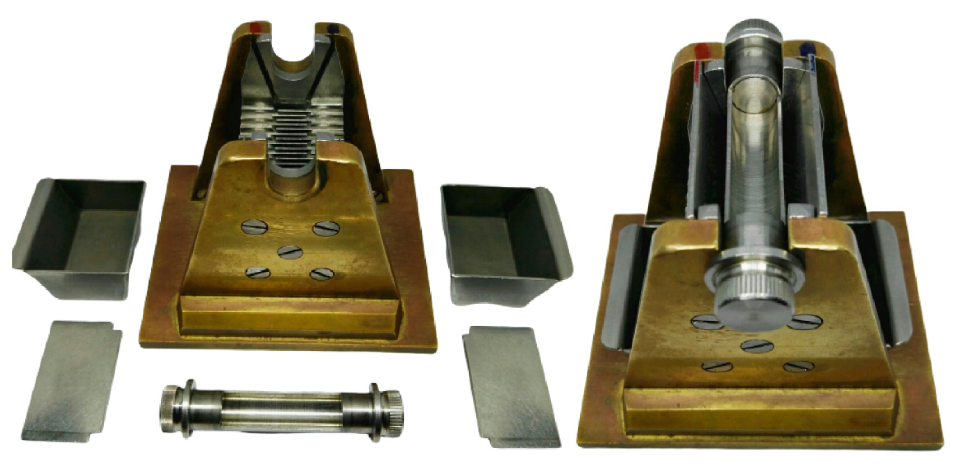
The recovered amount of the heavy fraction is generally much greater than what is strictly needed to prepare a grain mount. In order to obtain a representative aliquot of the heavy fraction, the latter needs to be repeatedly split into parts by using a micro-riffle box with 2-mm-wide slots and a 4-cm-long holder (Figure 3). The use of the Parfenoff cone or, worse, of a spoon or spatula is not recommended, especially when particles with different grain sizes and shapes occur in the sample.
NB: The minimum quantity needed for the grain mount is 3–5 mg. It is wise to keep in the archive the remaining part of the heavy-mineral fraction for replicate analyses and future investigations.
The split aliquot is temporarily poured out on a small (e.g., 7 × 5 cm) piece of clean white paper folded and refolded to prevent contamination and appropriately labeled. In the meanwhile, a digital hot plate covered by a clean aluminum foil is warmed up to ~130 °C. I advise to place between three and five glass slides (76 × 24 mm), carefully cleaned with paper and denatured alcohol to remove any trace of haloes and dust, on the upper left part of the hot plate. In the same way, an equal number of 22 × 22-mm cover slips are cleaned and warmed up. A glass slide and a cover slip are gently pushed with a toothpick to the lower right corner of the hot plate. Next, a drop of Canada balsam (n = 1.54) with the appropriate viscosity (not all brands perform in the best way) is picked up with a spatula and placed on the cover slip.
NB: The heavy-mineral mount and the cover slip should be positioned in an asymmetric position, approximately in the middle of the left half of the slide. This enables using the entire area of the mount during point counting.
After a couple of minutes, the Canada balsam is warm enough. The refolded paper containing the split heavy fraction is opened and used to pour out carefully all grains within the Canada balsam. To prepare a single layer of grains avoiding overlaps, we suggest spreading them around evenly with a clean toothpick conveniently held inclined by ca. 45° and rotating it quickly, avoiding to concentrate the grains close to the edges of the glass slide. With another toothpick, the cover slip is moved off the edge of the hot plate and picked up between fingers holding it by the sides to avoid burns. To avoid formation of air bubbles, the cover slip is overturned, placed tilted by ca. 45° by the edge of the glass slide, and let lying well-centered on the melted Canada balsam.
NB: The hot plate should be very slightly inclined toward the back of the fume hood to facilitate spreading the balsam and expelling all air bubbles.
After a couple of minutes necessary to polymerize the hot Canada balsam and let the air out, a light pressure is applied with a toothpick to minimize the thickness of the grain mount. This precaution is necessary, because thick grain mounts may not be observed with objectives with large magnification (e.g., 63×). If the amount of Canada balsam is insufficient to fill the space among grains —which may happen with bimodal mounts, including medium-sand particles—an additional drop of bounding resin picked up with a spatula can be added with a clean toothpick from the edge of the cover slip. The drop will melt soon and, thanks to the gentle tilt of the hot plate, will gradually flow and fill up the voids among the grains. The mount is now ready. You can rotate it with the toothpick to the edge of the hot plate, pick it up with a tong, and immerge in a small beaker filled with tap water to quench it. Finally, the mount is cleaned with alcohol and paper to eliminate all balsam residues, labeled with the proper sample name, and archived in slide holders.
8. Conclusions
This article, born from the experience gained in twenty years of heavy-mineral studies, illustrates in detail practical solutions apt to optimize workflow and avoid common mistakes. Our goal is to fill a gap in technical knowledge opened in the last half-century—a period during which both provenance-analysis techniques and sensitivity to environmental safety issues have rapidly increased—thus responding to the growing needs of students, researchers, and professionals from the industry. We indicate how, with handmade tools and a clever protocol design, mineral separations can be performed, minimizing time and cost on one side and improving quality of the results on the other. The illustrated procedure allows a skilled operator to obtain clean fractions of any grain size and to separate minerals not only from sand but also from finer and finest sediments, thus enabling grain by a grain analysis of particles down to a size of few microns. High-resolution quantitative provenance analysis of the entire grain-size spectrum thus becomes possible, targeting soils, fluvial suspended loads, eolian dust, and muds deposited in any environment, from the land to the deep sea. Such a performance, however, requires to make the correct decisions, from the first essential step represented by sampling in the field to the choice of the appropriate size-window for analysis, and to follow the correct procedures aimed at a complete recovery of the targeted minerals in the laboratory. The proposed practical handbook provides the beginner, as well as the experienced researcher, with a friendly protocol, standard but also adaptable to diverse needs, as an essential requirement for the comparison and consistency of data produced in different laboratories.
Funding
Funding provided by Projects MIUR-PRIN 2015EC9PJ5 “The subduction and exhumation of the continental lithosphere: Their effects on the structure and evolution of the orogens” and MIUR—Dipartimenti di Eccellenza 2018–2022, Department of Earth and Environmental Sciences, University of Milano-Bicocca.
Acknowledgments
This little handbook is dedicated to my wife, Giovanna Castiglioni and to all my students and colleagues who have helped me to apply and continuously refine the separation techniques illustrated here, including Pietro Vignola, Paolo Gentile, Danilo Bersani, Nicoletta Fusi, Marta Padoan, Mara Limonta, Laura Borromeo, Marta Barbarano, Guido Pastore, Eleonora Botti, and Christian France-Lanord. A special thought is for Maria Mange for her fundamental contribution to heavy-mineral studies and to Eduardo Garzanti for years of encouragements and continuing challenges to push forward the limits of heavy-mineral research.
Conflicts of Interest
The author declares no conflicts of interest.
References
- De Filippi, F. Sulla costituzione geologica della pianura e delle colline della Lombardia. Annu. Univers. Stat. 1839, 59, 225–248. [Google Scholar]
- Artini, E. Intorno alla composizione mineralogica delle sabbie del Ticino. Giornale di Mineralogia Cristallografia e Petrologia Pavia 1891, 2, 177–195. [Google Scholar]
- Garzanti, E.; Andò, S. Heavy Minerals for Junior Woodchucks. Minerals 2019, 9, 148. [Google Scholar] [CrossRef] [Green Version]
- Carver, R.E. Heavy-Mineral Separation. Chap. 18 in Procedures in Sedimentary Petrology; Carver, R.E., Ed.; John Wiley: Hoboken, NJ, USA, 1971. [Google Scholar]
- Mange, M.A.; Wright, D.T. Heavy Minerals in Use; Developments in Sedimentology Series; Elsevier: Amsterdam, The Netherlands, 2007; Volume 58, 1283p. [Google Scholar]
- Morton, A.; McGill, P. Correlation of Hydrocarbon Reservoir Sandstones Using Heavy Mineral Provenance Signatures: Examples from the North Sea and Adjacent Areas. Minerals 2018, 8, 564. [Google Scholar] [CrossRef] [Green Version]
- Krumbein, W.C.; Pettijohn, F.J. Manual of Sedimentary Petrography; D. Appleton-Century: New York, NY, USA, 1938; 549p. [Google Scholar]
- Hutton, C.O. Studies of heavy detrital minerals. Bull. Geol. Soc. Am. 1950, 61, 635–710. [Google Scholar] [CrossRef]
- Pettijohn, F.J.; Potter, P.E.; Siever, R. Sand and Sandstone; Springer: New York, NY, USA, 1972; 618p. [Google Scholar]
- Hutchison, C.S. Laboratory Handbook of Petrographic Techniques; John Wiley & Sons: Hoboken, NJ, USA, 1974. [Google Scholar]
- Callahan, J. A nontoxic heavy liquid and inexpensive filters for separation of mineral grains. J. Sediment. Petrol. 1987, 57, 765–766. [Google Scholar] [CrossRef]
- Fessenden, F.W. Removal of heavy liquid separates from glass centrifuge tubes. J. Sediment. Petrol. 1959, 29, 621. [Google Scholar] [CrossRef]
- Scull, B.J. Removal of heavy liquid separates from glass centrifuge tubes—Alternate method. J. Sediment. Petrol. 1960, 30, 626. [Google Scholar] [CrossRef]
- Galli, A.; Panzeri, L.; Martini, M.; Sibilia, E.; Vignola, P.; Andò, S.; Pini, R.; Rossi, P.M. Optically stimulated luminescence dating of a stratigraphic Late Glacial–Holocene sequence in the Po plain (Bubano quarry, Bologna, Italy). Quat. Int. 2009, 199, 45–55. [Google Scholar] [CrossRef]
- Mehra, O.P.; Jackson, M.L. Iron Oxide Removal from Soils and Clays by a Dithionite-Citrate System Buffered with Sodium Bicarbonate. Clays Clay Miner. 1958, 7, 317–327. [Google Scholar] [CrossRef]
- Garzanti, E.; Andò, S.; Vezzoli, G. Settling equivalence of detrital minerals and grain-size dependence of sediment composition. Earth Planet. Sci. Lett. 2008, 273, 138–151. [Google Scholar] [CrossRef]
- Garzanti, E.; Andò, S.; Vezzoli, G. Grain-size dependence of sediment composition and environmental bias in provenance studies. Earth Planet. Sci. Lett. 2009, 277, 422–432. [Google Scholar] [CrossRef]
- Andò, S.; Vignola, P.; Garzanti, E. Raman counting: A new method to determine provenance of silt. Rend. Lincei 2011, 22, 327–347. [Google Scholar] [CrossRef]
- Henningsen, D. Crushing of sedimentary rock samples and its effect on shape and number of heavy minerals. Sedimentology 1967, 8, 537–546. [Google Scholar] [CrossRef]
- Mange, M.A.; Maurer, H.F.W. Heavy Minerals in Colour; Chapman and Hall: London, UK, 1992; 147p. [Google Scholar]
- Parfenoff, A.; Pomerol, C.; Tourenq, J. Les Minéraux en Grains—Méthodes d’ Étude et Détermination; Masson: Paris, France, 1970; 578p. [Google Scholar]
- Garzanti, E.; Vezzoli, G.; Andò, S.; Limonta, M.; Borromeo, L.; France-Lanord, C. Provenance of Bengal Shelf Sediments: 2. Petrology and Geochemistry of Sand. Minerals 2019, 9, 642. [Google Scholar]
- Garzanti, E.; Andò, S.; France-Lanord, C.; Vezzoli, G.; Censi, P.; Galy, V.; Najman, Y. Mineralogical and chemical variability of fluvial sediments 1. Bedload sand (Ganga–Brahmaputra, Bangladesh). Earth Planet. Sci. Lett. 2010, 299, 368–381. [Google Scholar] [CrossRef]
- Chakoumakos, B.C.; Murakami, T.; Lumpkin, G.R.; Ewing, R.C. Alpha-decay—Induced fracturing in zircon: The transition from the crystalline to the metamict state. Science 1987, 236, 1556–1559. [Google Scholar] [CrossRef]
- Chisholm, E.K.; Sircombe, K.; DiBugnara, D. Handbook of Geochronology Mineral Separation Laboratory Techniques; Chisholm, E.K., Sircombe, K., DiBugnara, D., Eds.; Geoscience Australia: Canberra, Australia, 2014; Volume 46, pp. 1–45. [Google Scholar]
- Malusà, M.; Garzanti, E. The Sedimentology of Detrital Thermochronology. In Fission-Track Thermochronology and its Application to Geology; Springer: Cham, Switzerland, 2019; pp. 123–143. [Google Scholar]
- Resentini, A.; Malusà, M.G.; Garzanti, E. MinSORTING: An Excel® worksheet for modelling mineral grain-size distribution in sediments, with application to detrital geochronology and provenance studies. Comput. Geosci. 2013, 59, 90–97. [Google Scholar] [CrossRef]
- Vermeesch, P.; Rittner, M.; Petrou, E.; Omma, J.; Mattinson, C.; Garzanti, E. High Throughput Petrochronology and Sedimentary Provenance Analysis by Automated Phase Mapping and LAICPMS. Geochem. Geophys. Geosyst. 2017, 18, 4096–4109. [Google Scholar] [CrossRef]
- Yokoyama, K.; Amano, K.; Taira, A.; Saito, Y. Mineralogy of Silts from the Bengal Fan. Proc. ODP Sci. Results 1990, 116, 59–73. [Google Scholar]
- Garzanti, E.; Andó, S.; France-Lanord, C.; Censi, P.; Vignola, P.; Galy, V.; Lupker, M. Mineralogical and chemical variability of fluvial sediments 2. Suspended-load silt (Ganga–Brahmaputra, Bangladesh). Earth Planet. Sci. Lett. 2011, 302, 107–120. [Google Scholar] [CrossRef]
- Delmonte, B.; Paleari, C.I.; Andò, S.; Garzanti, E.; Andersson, P.S.; Petit, J.R.; Crosta, X.; Narcisi, B.; Baroni, C.; Salvatore, M.C.; et al. Causes of dust size variability in central East Antarctica (Dome B): Atmospheric transport from expanded South American sources during Marine Isotope Stage 2. Quat. Sci. Rev. 2017, 168, 55–68. [Google Scholar] [CrossRef] [Green Version]
- Caracciolo, L.; Andò, S.; Vermeesch, P.; Garzanti, E.; McCabe, R.; Barbarano, M.; Paleari, C.; Rittner, M.; Pearce, T. A multidisciplinary approach for the quantitative provenance analysis of siltstone. Mesozoic Mandawa Basin, southeastern Tanzania. Geol. Soc. Lond. Spec. Publ. 2019, 484, SP484-2018. [Google Scholar] [CrossRef]
- Andò, S.; Aharonovich, S.; Hahn, A.; George, S.C.; Clift, P.D.; Garzanti, E. Integrating heavy-mineral, geochemical and biomarker analyses of Plio-Pleistocene sandy and silty turbidites: A novel approach for provenance studies (Indus Fan, IODP Expedition 355). Geol. Mag. 2019. [Google Scholar] [CrossRef]
- Borromeo, L.; Andò, S.; France-Lanord, C.; Coletti, G.; Hahn, A.; Garzanti, E. Provenance of Bengal Shelf Sediments: 1. Mineralogy and Geochemistry of Silt. Minerals 2019, 9, 640. [Google Scholar] [CrossRef] [Green Version]
Figure 1.
Tissue sieve made with nylon mesh. From bottom to top: toothpick and 100-cm2-piece of nylon mesh; PVC ring and tissue sieve ready for use.
Figure 1.
Tissue sieve made with nylon mesh. From bottom to top: toothpick and 100-cm2-piece of nylon mesh; PVC ring and tissue sieve ready for use.

Figure 2.
Manual press designed to split sedimentary rocks using protective eye goggles.
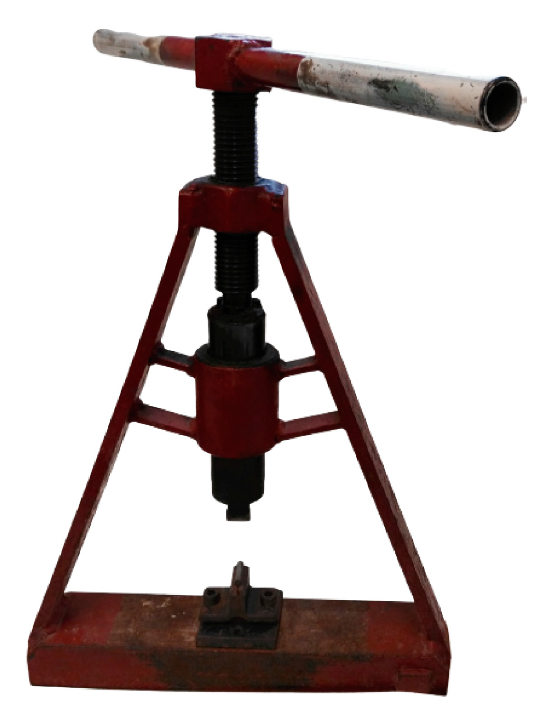
Figure 3.
Riffle box designed to split sediments (length 10 cm, width 8 cm, and height 8 cm).

Figure 4.
Dense minerals concentrate in the sieve bottom pan during wet sieving with a sketch of the apparatus described in Section 5.1.
Figure 4.
Dense minerals concentrate in the sieve bottom pan during wet sieving with a sketch of the apparatus described in Section 5.1.
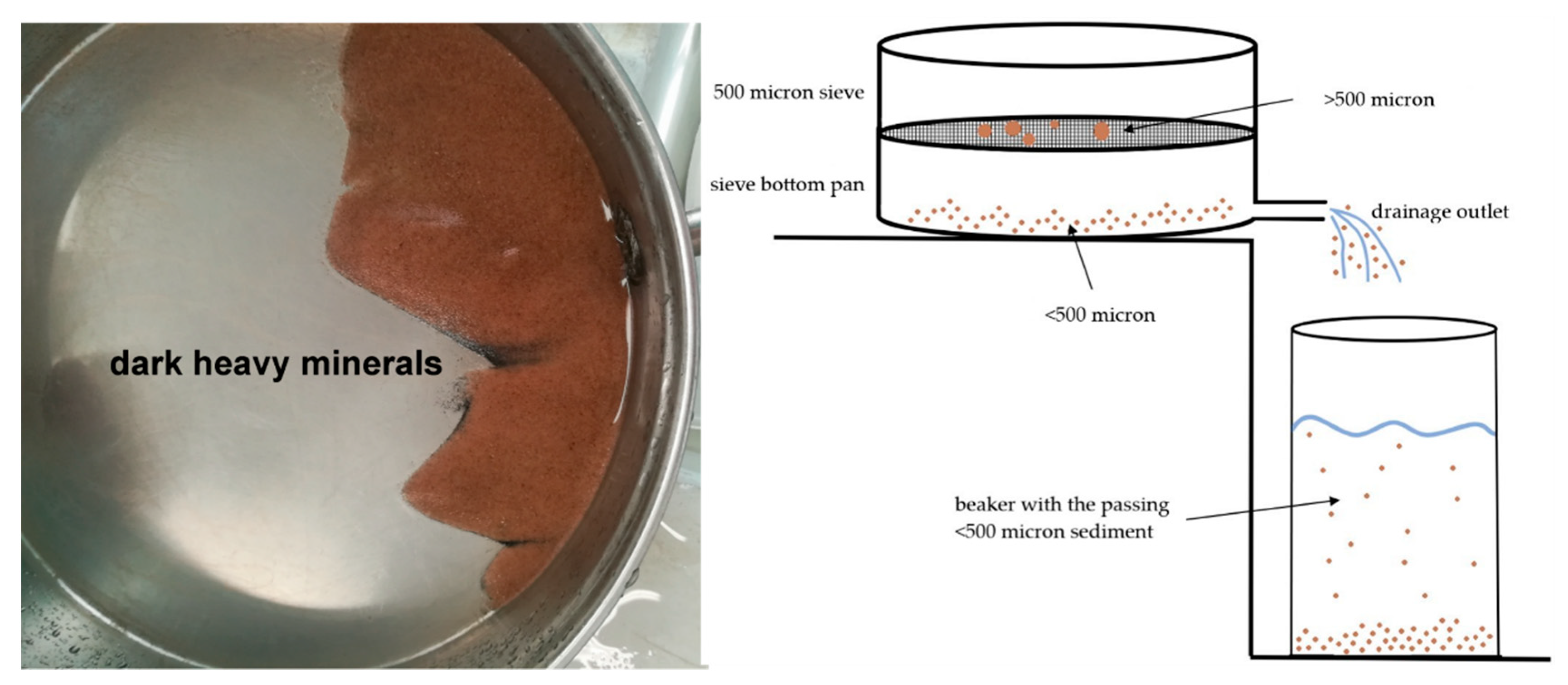
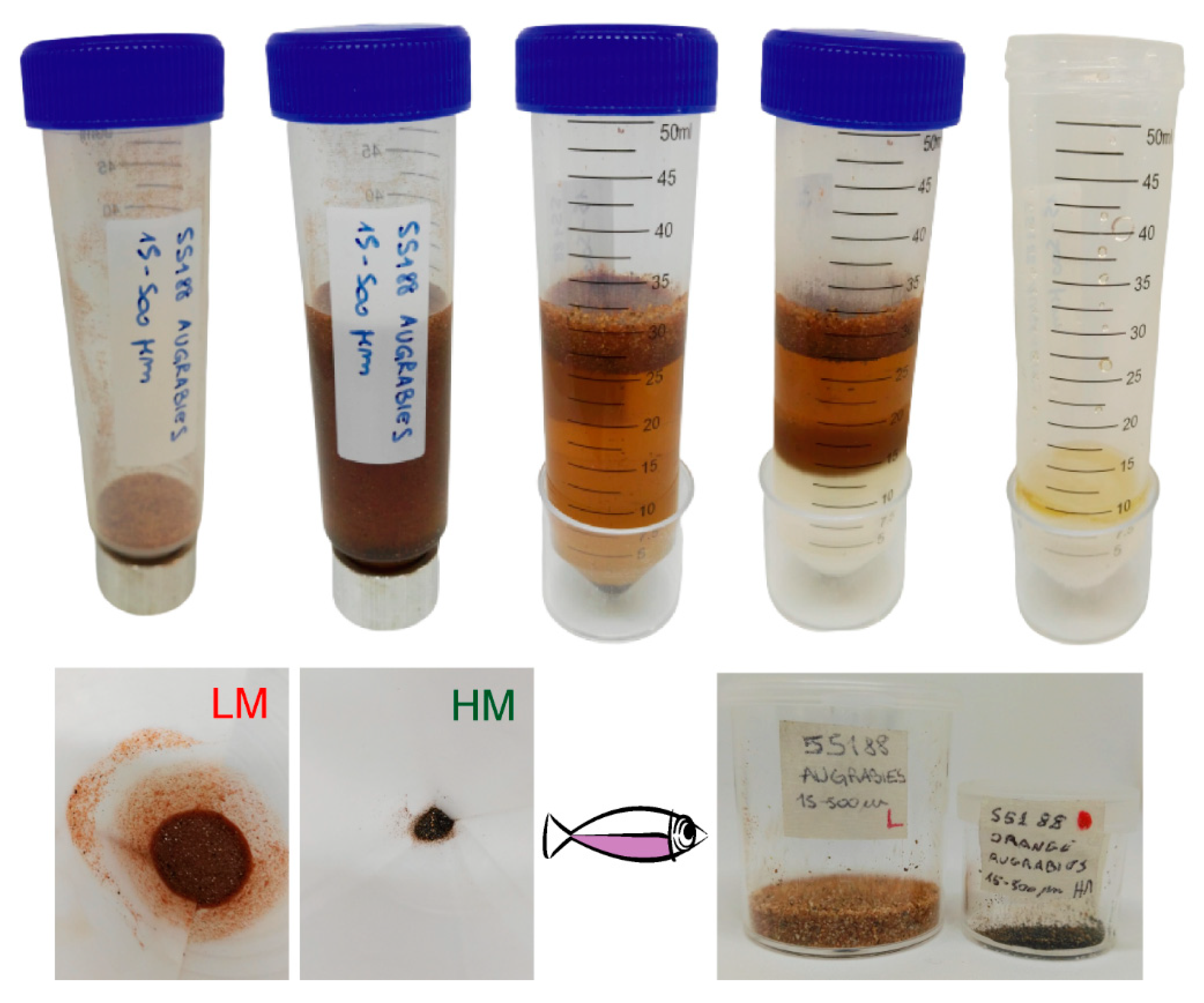
Figure 5.
Gravimetric separation sequence with SPT and conic tubes, to separate the dense and light fractions in a centrifuge. From left to right in the first line: initial dry sample, sample mixed with SPT after shaking, the light minerals (LM) and the heavy minerals (HM) separated by SPT after the centrifugation, sample with frost-heavy fraction in the bottom and unfrozen light fraction in the top of the conic tube, and empty conic tube after recovering of the light fraction with the heavy minerals still in the ice. Second line: washed light minerals in the paper filter, washed dark heavy minerals in the paper filter, and light and heavy minerals dried and stored and labeled in plastic boxes after weighing.


Table 1.
Laboratory data sheet for sieving medium silt to medium sand range (15–500 μm). Percentage of dense (>2.90 g/cm3) fraction separated in the lab (%HM); grams (g).
Table 1.
Laboratory data sheet for sieving medium silt to medium sand range (15–500 μm). Percentage of dense (>2.90 g/cm3) fraction separated in the lab (%HM); grams (g).
| Sample Name | g | ||||||
|---|---|---|---|---|---|---|---|
| Initial dry weight | |||||||
| >500 μm | g used | g Light Minerals | g Heavy Minerals | %HM | Mount ready | ||
| 15–500 μm | |||||||
| <15 μm | |||||||
| Total weight | |||||||
| Splitter with Parfenoff |  | Dry sieving | | Settling tubes | | ||
| Micro-Splitter | | Wet sieving | |
© 2020 by the author. Licensee MDPI, Basel, Switzerland. This article is an open access article distributed under the terms and conditions of the Creative Commons Attribution (CC BY) license (http://creativecommons.org/licenses/by/4.0/).
Share and Cite
MDPI and ACS Style
Andò, S. Gravimetric Separation of Heavy Minerals in Sediments and Rocks. Minerals 2020, 10, 273. https://doi.org/10.3390/min10030273
AMA Style
Andò S. Gravimetric Separation of Heavy Minerals in Sediments and Rocks. Minerals. 2020; 10(3):273. https://doi.org/10.3390/min10030273
Chicago/Turabian StyleAndò, Sergio. 2020. "Gravimetric Separation of Heavy Minerals in Sediments and Rocks" Minerals 10, no. 3: 273. https://doi.org/10.3390/min10030273
Note that from the first issue of 2016, this journal uses article numbers instead of page numbers. See further details here.