Article

The Influence of Slag Tapping Method on the Efficiency of Stabilization Treatment of Electric Arc Furnace Carbon Steel Slag (EAF-C)

Dipartimento di Meccanica, Politecnico di Milano, Via La Masa 1, 20156 Milano, Italy
*
Author to whom correspondence should be addressed.
Minerals 2019, 9(11), 706; https://doi.org/10.3390/min9110706
Submission received: 15 October 2019 / Revised: 7 November 2019 / Accepted: 12 November 2019 / Published: 14 November 2019
(This article belongs to the Special Issue Metallurgical Slags)

Abstract

:
Studies conducted over the past 10 years have demonstrated the technical suitability of the electric arc furnace slag as an alternative to natural stone in several applications. Steel slag can be profitably used as a road surface layer, for foundations and embankments, or for concrete aggregates. However, a strong limitation to their use is due to the presence of toxic metals (Ba, Cr, V, Mo, etc.) that can be released into the environment in particular conditions, especially for unbound products in which the slag can come into contact with water. Recent studies have investigated the role of chemical composition and microstructure of slag on toxic metal leaching, allowing for the design of suitable stabilization treatments for hindering such leaching. In this work, four batches of electric arc furnace carbon steel slag underwent a stabilization treatment and the obtained results were compared. In two batches, the stabilizer was added directly in the slag pot and the slag was cooled down in the same pot. The other two batches were stabilized during the downfall from slag door to slag pit. Several slag samples were collected before and after the stabilization treatment and were characterized by means of ED-XRF, XRD, and SEM analysis. Leaching tests were carried out in agreement with EN 12457-2 standard on 4 mm granulated slag, and the leachate concentration was compared with the current Italian limits listed in D.M. 3 August 2005 N. 201 and D.M. 5 April 2006 N. 186. The results clearly indicated that the cooling in the slag pot improved the efficiency of the stabilization treatment, leading to a complete transformation of the microstructure by a full development of homogeneous gehlenite matrix and a coarsening of Cr-spinels, assuring better toxic metal retention behavior. On the contrary, stabilization in the slag-pit was rapid and reduced the interaction between slag and stabilizer, leading only to partial transformation of larnite into gehlenite, and also reducing the coarsening of Cr-spinel. In addition, a layering effect was observed, resulting in an inhomogeneous product from top to bottom in terms of chemical composition, microstructure, and leaching behavior.

1. Introduction

The last 10 years consolidated the position of steelmaking slag as a suitable technical alternative to natural stones for several engineering applications, such as road construction and concrete production [1,2,3,4].
After an initial stationary consumption of steelmaking slag by employing the whole amount of produced material, since 2010 the production of slag has increased by about 25% and its use has overcome the stocks of about 3%, reaching is maximum in 2008 (25 Mt/y of recycled slag). The employment of steel slag as road construction material followed the same trend, now representing the 45%–50% of the whole amount of the recycled slag. In this scenario, electric arc furnace carbon steel slag (EAF-C slag) production oscillates around 5 Mt/y (Figure 1).
The successful conversion of steelmaking slag into a valuable product is due to the development of several stabilization treatments able to solve some of the issues concerning this material: volume expansion, self-dusting, and toxic metal leaching. Stabilization treatments have been applied to all the different types of steelmaking slag, such as basic oxygen furnace (BOF) slag, electric arc furnace (EAF) slag, and secondary metallurgy (LF, AOD, VOD) slag.
Different approaches were proposed to solve one of the most important problems that affects BOF, EAF, and ladle slag—the volume instability. For the end-user of the slag, that is, the construction industry, volume stability means the slag particles must maintain their volume for a long term. If not, that is, when the particles shrink or swell, the integrity of the concrete or asphalt is compromised. Other than dicalcium silicate (β→γ) transformation and CaO and/or MgO hydration, thermal shrinkage also afflicts slag, producing volume instability and disintegration.
Chemical modification outside the furnace was demonstrated to be a good technique to solve instability problems (both volume instability and self-dusting). Kuhn et al. [6] developed a process for dissolving a large quantity of SiO2 (~10 wt %) in carbon steelmaking slags. By co-injecting oxygen, the slag is stirred and FeO in the slag is oxidized to Fe2O3, generating the required heat to dissolve the SiO2. SiO2 reacts with exceeding CaO, avoiding hydration problem and reducing the weathering time. The process is currently operational at ThyssenKrupp Duisburg and ArcelorMittal Gent. Silica addition also acts on stability of dicalcium silicate. Kalina et al. [7] found that SiO2-saturated dicalcium silicate (2CaO·SiO2) does not suffer from crystalline transformation, thus limiting the dusting effect. Similar results were found by Yu-Chen Lee [8]. In his research, different techniques were tested to reduce the volume instability of BOF slag, but only sand addition demonstrated its efficiency over the problems.
An alternative stabilizer of quartz is alumina, which causes the formation of the stable dicalcium aluminosilicate (or gehlenite) complex [9]. The presence of alumina reduces slag basicity and moves the system out of the dicalcium silicate (or larnite) stable region on the CaO-SiO2-Al2O3 phase diagram [10]. Actually, alumina requirement depended on the binary basicity index (CaO/SiO2) of the slag.
The effect of rapid cooling on larnite transformation has also been studied. Indeed, quenching should stabilize the β-2CaO·SiO2 grains and prevent the disintegration of the slag into a fine powder. In theory, rapid cooling should avoid staying in the range of β-γ transformation (700–500 °C) for enough time to promote the change in lattice structure, thus freezing the β-2CaO·SiO2 form. Nevertheless, industrial trials by Erdmann et al. [11] suggest that slow cooling, that is, slag pot cooling during several days, leads to a denser and coarser slag than the commonly used slag pit cooling. Similar trials performed on AOD slags also seem to corroborate that the level of fines—linked to thermal shrinkage—can be mitigated through very slow cooling in slag pots.
One of the most investigated environmental problems of steelmaking slag is Cr6+ release. Hexavalent form is the most reactive and dangerous (it is classified as carcinogenic by the World Health Organization). Different studies aimed to find a way to reduce or inhibit the leaching of Cr oxyanion. The milestone in this subject is the RFCS (Research Fund for Coal and Steel) project n° 7215-PP/044 [12]. In this project, the correlation between chemical composition and chromium leaching for stainless steel steelmaking slag was identified, formulating a simple parameter (sp-factor) to forecast the Cr leaching behavior of the slag. On the basis of this result, a method for treating EAF stainless steel slag (EAF-SS) was developed [13]. During the slag tapping, stabilizers are added into the liquid to promote the nucleation of spinel-type phases in the solidified slag. Among several stabilizers (MgO, FeO, SiO2, and Al2O3) a mix 75–85 wt % Al2O3 and 10–20 wt % SiO2 (called TE 75) gave the best results—the modified slag being without dusting problems and the Cr leaching being maintained under the regulation limits. However, the effectiveness of sp-factor has been recently disproved in terms of predicting the leaching of Cr in carbon steel slag [7]. In fact, in such slag the Cr leaching is controlled by the Cr solved in silicates and aluminates [14,15]. In this regard, Geißler et al. [16] defined a new index, called cs-factor, which accounts for the Cr bound in calcium silicates, more solvable in water than spinels. Even by pure quartz addition, spinel formation and Cr fixation can be achieved, as stated by Mombelli et al. [17]. In detail, the injection of quartz or sand during slag tapping significantly reduced the slag’s melting temperature, allowing it to be maintained in a liquid state for a prolonged period of time. This permits spinels to aggregate in larger and more stable structures.
The proven efficiency of in-tapping chemical stabilization treatment of electrical furnace slag was never investigated as a function of the tapping method—slag-pot or slag-pit tapping. The former consists of slag falling in a suitable container lined with refractory material (slag ladle or pot), whereas the latter on slag falling on a collecting area (the slag pit), both placed at a lower level than the electric arc furnace. The main difference between pit and pot tapping is in the cooling rate—in the ladle, the slag solidifies with a slow cooling rate, taking approximately 20–24 h, whereas in the pit, the slag is fast cooled by the use of air or water splashes, which limit the dusting effect. This difference in cooling rate may affect the reaction time between slag and stabilizers. For this reason, in this paper, four batches of EAF carbon steel slag (two treated in a pot, two treated in a pit) were investigated. Morphological and crystallographic characterization were carried out to understand the influence of stabilizers on the phase arrangement, whereas the leaching test according to EN 12457-2 standard was used to investigate the leaching behavior of such slag. From the comparison of the different batches, the role of MgO in the slag was clarified. MgO-compounds (i.e., α-Ca2SiO4) tend to react with SiO2 to form merwinite instead of gehlenite. The key role of mayenite as a marker of the efficacy of the stabilization treatment is also highlighted. Finally, one of the novel findings is that the slag-pit favors the layering of the slag, inducing different behaviors from top to bottom of the treated pile.

2. Materials and Methods

2.1. Description of the Analyzed Slag

The EAF slags were provided by different electric steelworks associated with different steel productions. Several samples of both as-received and stabilized conditions were collected and investigated, classifying the different slag into four batches according to the production site and tapping method (Table 1).
Group A slag was derived from the production of rebar steel, and the stabilization treatment consisted of the addition of pure quartz into the fluid slag during its tapping, allowing the production of a continuous flow of treated slag with a specific chemical composition. The dosing device consisted of a sand silo equipped with an automatic vibrating delivery table and with a chute positioned downstream from the delivery device to continuously carry the sand in the pot. The added quartz had an average particle size between 1 and 5 mm, with 90% included in the 1–2 mm range and its amount being comprised between 5% and 15% by weight of the slag, depending on the initial chemical composition of the slag to be treated [17]. Two different heats, before (samples A1 and A2) and after stabilization treatment (samples A1M and A2M) were analyzed.
Group B slag belonged to the production of quality steels. Siliceous sand (1–4 mm) was conveyed to slag-pot during the tapping by means of dilute phase pneumatic conveying system. Approximately 8% to 12% sand was injected at 3–5 bar as a function of the tapped slag amount. Two samples were investigated: as-received (B) and stabilized (BM) forms.
Group C, as well B, came from the production of quality steels, but the slag after tapping was collected in a pit. During the path between the slag door and the pit, the slag flux was intercepted by the stabilizer added through a pneumatic transport system, instead of its discharging by gravity. Thus, the mixing was assured by the high kinetic energy of the stabilizer flow. The injection assured the decrease of the powdered material losses caused by the convective air flow and EAF fume plant suction, thanks to the high coherence of the material flow and the right grain size of the powder. The pilot plant consisted of a silo stocking the stabilizer and of a metering valve supplying and conveying it through the pneumatic transport to a nozzle that lay close to the EAF door. Dosing of stabilizer was controlled by modifying air pressures and flow (1–3.5 bar; 150–300 Nm3/h), stabilizer flow (0–140 kg/min), and silo pressure (2–4 bar) [18]. Several trials were performed to evaluate the impact of the different process parameters on the microstructure transformation. Two as-received slags were characterized (C1, C2) and then different samples that varied the stabilizer addition conditions were collected. Details are reported in Table 2.
Group D slag was the second batch of slag-pit treated slag. With respect to group C, the EAF tapped the slag in a tunnel behind the furnace. The stabilizer addition was carried out by two pneumatic lances with different injection angles, aimed to intercept the slag flow both in-flight and in the contact area with the pit floor. Fine quartzite (10 wt % on the total slag mass) was added and samples were collected at different layers. Stabilized sample (DM) was collected in the slag flow-pit floor contact area, whereas two additional samples were collected far from the mixing zone, one under the solidified slag pile (DMd) and one on its top (DMu).

2.2. Chemical, Crystallographic, and Microstructural Characterization

The slag chemical composition was determined by Energy Dispersive X-Ray Fluorescence (ED-XRF) analysis through the Ametec Spectro Xepos spectrometer in Helium atmosphere on 5 g of powdered slag. The average chemical compositions of the as-received and treated slag are reported in Table 3.
A morphological and microstructural investigation was performed by means of XRD and SEM analyses. X-ray diffraction (XRD) data were collected using a Bruker D8 Advance diffractometer in a θ−θ configuration employing the Cu Kα radiation (λ = 1.54 Å) with a fixed divergence slit size 0.5° and a rotating sample stage. Grinded samples (average diameter 15 μm) were scanned between 10° and 80° (step size of 0.007°) with the Vantec detector. The morphological and microstructural characterization was performed by Zeiss EVO50 scanning electron microscopy (SEM, Carl Zeiss AG, Oberkochen, Germany) equipped with an Oxford Inca Energy Dispersive Spectroscopy (EDS) probe (Oxford Instruments, High Wycombe, UK). The slag was moulded in araldite-based resin before being ground and polished.

2.3. Leaching Test

Standard leaching tests were performed according to EN 12457-2 on granulated slag ranging from 4 to 0.1 mm. The fine fraction below 0.1 mm was discharged. The slag test portion was brought in contact with fixed volume of deionized water (10 L/kg) and stirred at 10 rpm by a rotatory mixer for 24 h. The test was based on the assumption that equilibrium or near-equilibrium was achieved between the liquid and solid phases during the test. The concentration limits taken as a reference are indicated in the Italian legislative decrees (D.M. 3 August 2005 N. 201 [19] and D.M. 5 April 2006 N. 186 [20]). Leached concentrations were measured by ICP-OES (induced coupled plasma-mass spectroscopy, detection limit 1 μg/L). At least three measurement for each sample were carried out.

3. Results

3.1. Leaching Test

Leaching test results are reported in Table 4. The analysis concentrated only on the elements that could actually be released by carbon steel EAF slag, namely, Ba, Cr, and V. The other parameters required by Italian legislation to determine the dangerousness of a slag are always below the limit or below the detection limit of the ICP, also demonstrated by Mombelli et al. in [21]. The leaching of toxic elements was reduced in all the samples that underwent the thermochemical treatment, even those with a specific difference that will be highlighted later. Also, a reduction of the leachate solution pH was achieved. In particular, it can be noted that the efficacy of stabilization treatment was less for the slag-pit tapped slag, whereas for the slag-pot tapped slag the stabilization reduced the leachate concentration significatively, even in the presence of very high elution in the as-received conditions.

3.2. Chemical, Crystallographic, and Microstructural Characterization

As reported in 
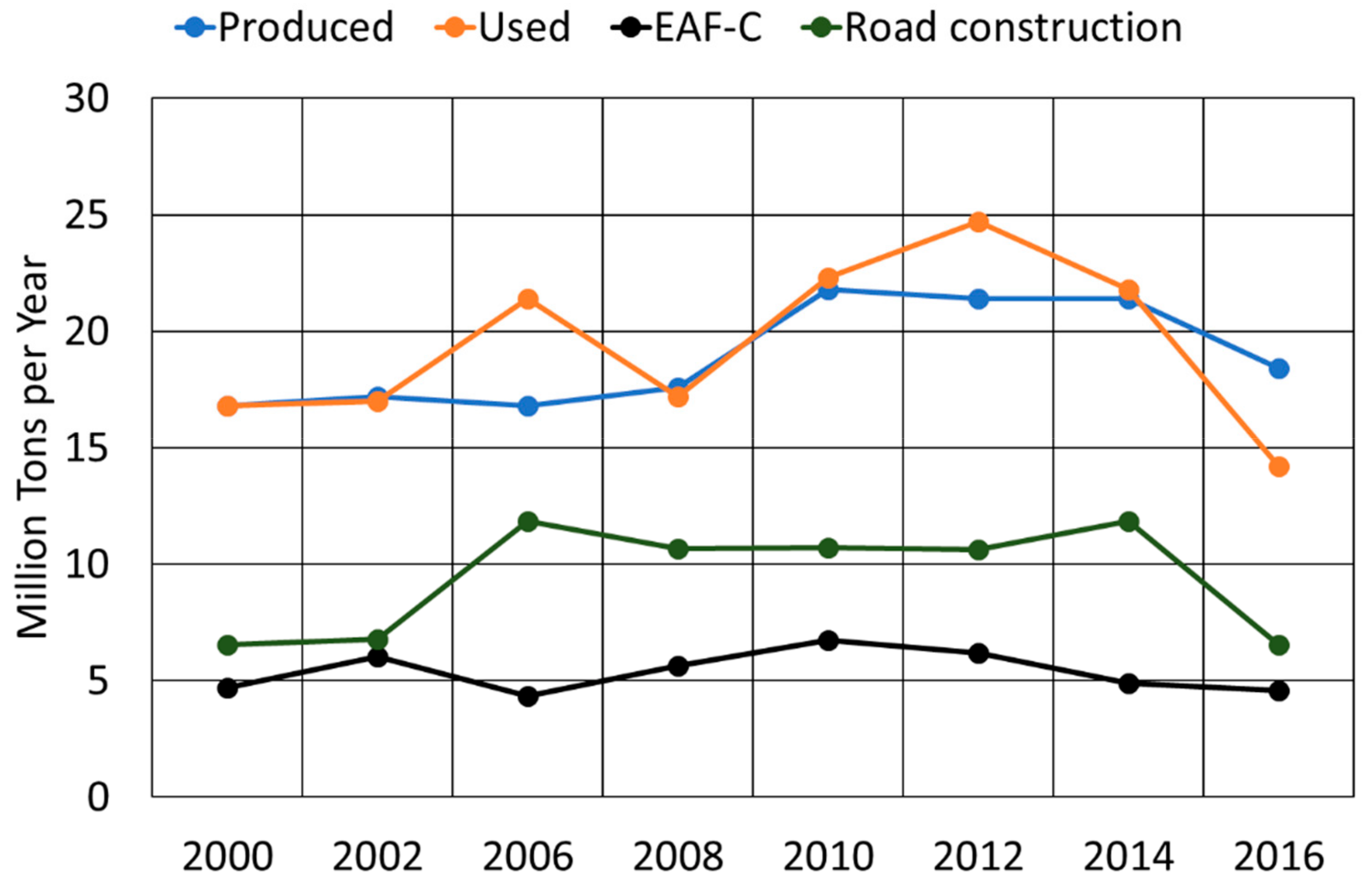
Figure 2, the stabilization treatment by quartz or sand addition can modify the chemical composition of the slag outside the furnace. By the correct addition, it is possible to change the chemical composition of a slag from the larnite stability field to the gehlenite–kirschsteinite stability field. Regarding the slag samples under examination, it seems that the stabilization treatment had a higher efficacy for the pot-tapped slag, as the A and B group samples fell exactly in the green areas of the ternary diagrams after the treatment [10]. On the contrary, the final chemical composition of the pit-tapped slag (C and D group samples) resulted far from the safety areas, even if the stabilizer amount injected was theoretically enough to move the slag to the safe chemical composition. It was probably the case that the quartz injection in the slag-pit had a high number of dispersed particles that were consumed (i.e., effectively conveyed to the slag) but did not react with it.
From a crystallographic and microstructural point of view, the different groups had different characteristics that needed to be analysed separately; even the different as-received slags were mainly formed by larnite, and wustite. After the stabilization treatment, different crystalline phases due to the interaction between stabilizer and molten slag could be identified. The analysis of the morphology of such phases can be used as an index of the efficiency of stabilization treatment.
Group A as-received slags were characterized by large presence of wustite ((Fe, Mg, Mn)O), larnite (2CaO·SiO2), and a small amount of Mg–Cr-spinels. Traces of gehlenite (Ca2Al(AlSi)O7) and brownmillerite (Ca2(Al, Fe3+)2O
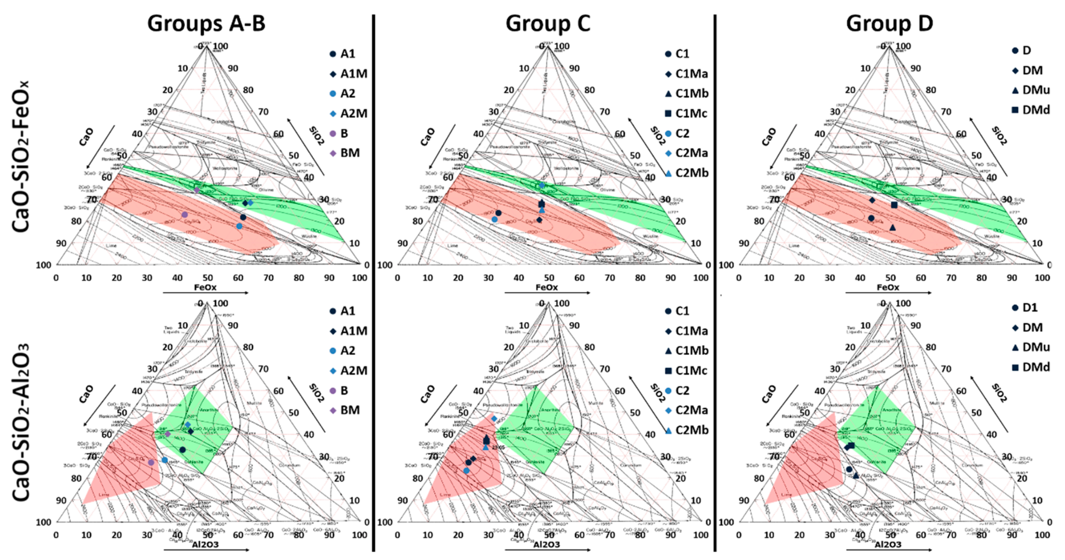
5) were also detected in sample A1 and A2, respectively (
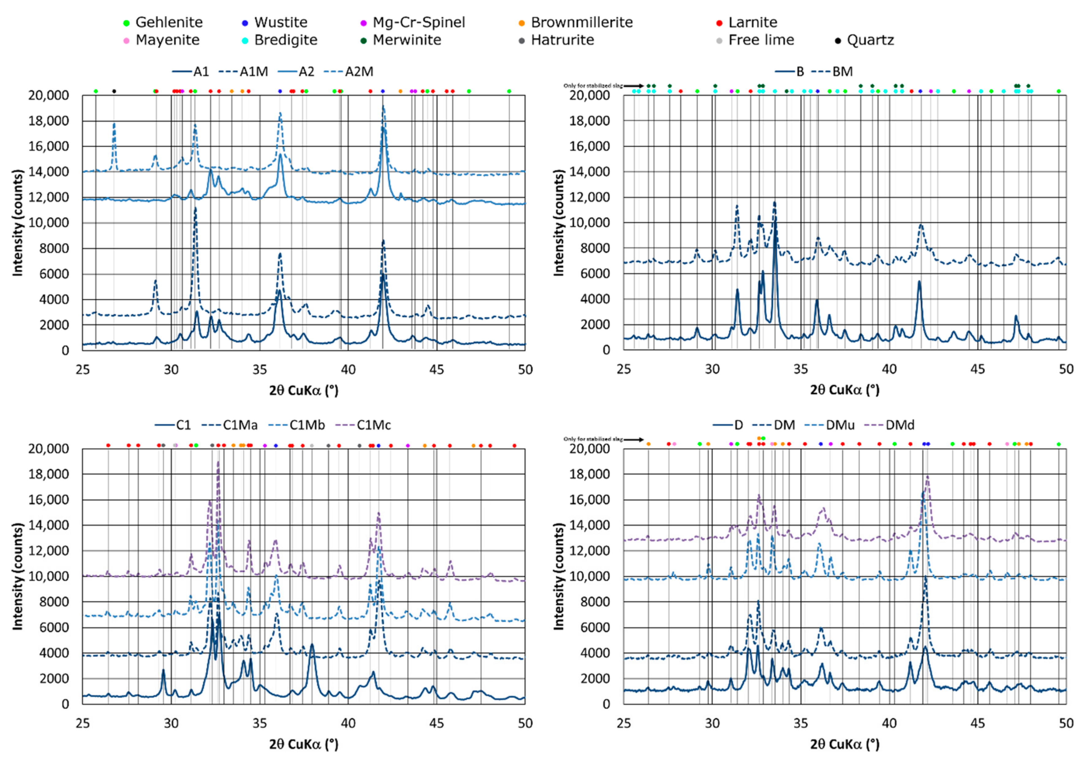
Figure 3). SEM analyses confirmed the results of XRD, allowing for the ability to characterize morphology and distribution of each structural constituent (Figure 4). As-received samples featured a high fraction of larnite, about 37% (A1 sample) and 31% (sample A2), estimated by selective dissolution in methanol–salicylic acid solution [22]. In sample A1, Mg–Cr-spinels (Sp mark in Figure 4) and gehlenite islands (G mark in Figure 4) were finely dispersed in larnite matrix (L mark). Wustite (W mark) had the typical dendritic form. In samples A2, wustite appeared thinner and more dispersed than in slag A1 and was surrounded by brownmillerite-type phase. In both as-received samples, chromium was mainly bound in spinel-like phases, even if important amounts were also detected in brownmillerite (0.5–0.6 atom %), larnite (0.15–0.17 atom %), and wustite (1.5–3.0 atom %). Vanadium and barium are mainly present in larnite (0.5–1.0 atom %; 0.03–0.04 atom %), brownmillerite (0.25–0.3 atom %), gehlenite (0.15 atom %) in sample A1, and mayenite (0.10 atom %) in the sample A2. The thermo-chemical treatment modified the slags’ microstructure. As pointed out in the XRD pattern (Figure 3), the admixed quartz led to another phase assemblage. In particular, larnite and brownmillerite reacted with SiO2 to form gehlenite. In fact, diffraction patterns pointed out very intense peaks typical of gehlenite–akermanite phases, whereas no more reflection of larnite and brownmillerite was present. In A2M samples, secondary peaks were also detected, probably associated with kirschsteinite that was present in solid solution with gehlenite.
Morphologically, the modified slag microstructures appeared homogeneous and constituted by a continuous gehlenite matrix where wustite and Mg–Cr-spinels were dispersed. The stirring effect of slag-pot contributed to homogenize the microstructure and to complete the diffusive reactions between the different phases. Wustite appeared finer and thinner with respect to the as-received condition, with pronounced dendritic structures. This aspect was associated with the reduction of slag melting temperature induced by quartz addition. Specifically, the admixed quartz reduced sensibly the melting temperature of the slag, allowing the slag mass to be maintained at liquid state for a longer time in the slag-pot [18]. In this way, wustite dendrites could further grow up, being surrounded by a totally molten phase. On the contrary, in as-received samples, wustite solidified in the free spaces between the larnite blocks that were already solid during the tapping.
In modified slag, the spinels were aggregated in larger structures than those retrieved in as-received conditions. The spinels were characterized by a perimeter-on-area ratio around 1 and were deprived of impurities (Si and Ca concentration below 1 wt %) that assured high stability [23]. Chromium was completely fixed in spinel phase, whereas barium was totally migrated into gehlenite matrix (0.10–0.15 atom %). In this form, the slag should be completely stable and hinder Ba, V, and Cr release. Detailed characterization of these slags is available in a previously published paper [17].
The developed treatment was successfully applied to slag produced during the production of quality alloyed steels. Such slag was characterized by very low FeO (~20 wt %) concentration and high fraction of MgO (12–13 wt %) (group B).
As indicated in Figure 2, the siliceous sand addition contributed to the moving up of the slag composition on the CaO-SiO2-FeOx ternary diagram toward the safe area (green region). However, the high MgO concentration in the slag prevented the formation of a correct microstructure, as MgO reacted with added silica to form CaO-MgO-SiO2 complex oxide (merwinite). The low FeO concentration stimulated the reaction between Mg and Si oxide, as the FeO fraction was not enough to complexify MgO under the form of Mg–wustite.
XRD analysis (Figure 3) confirms the phase diagrams observation. Diffraction patterns of the as-received (B) and stabilized (BM) samples pointed out very similar crystallographic composition. Intense peaks associated with bredigite and gehlenite were identified in the as-received sample. The siliceous sand addition stimulated the formation of a higher fraction of gehlenite and merwinite with respect to the as-received sample, as the bredigite peaks were now referred to merwinite, whereas gehlenite peak intensity increased. Merwinite is a magnesium calcium silicate usually found within blast-furnace slag that has low hydraulic properties. However, merwinite had the most part of its peaks overlapping with those of bredigite. Thus, SEM characterization is necessary to disentangle this doubt.
In the as-received sample (Figure 4), the matrix was composed of a solid solution of bredigite (Br) and merwinite (M). Bredigite is defined as α-Ca2SiO4 and has almost the same attitude to dissolve as larnite does. Moreover, bredigite tends to appear with a twinned structure and contains a higher BaO fraction in its structure. In the as-received sample, most of the Ba was bound in bredigite (0.6 atom %) and merwinite (0.10 atom %). During the elution test, the bredigite was significantly dissolved, whereas merwinite resisted the water etching, confirming its low hydraulic attitude that is comparable with gehlenite and wustite. Certainly, bredigite was mainly responsible for Ba leaching in this sample, and this can explain its high concentration in the leachate. Cr was mainly fixed in wustite (0.7–0.8 atom %) and spinel phases (38 atom %), whereas V was mainly in spinel (0.6–0.7 atom %) and merwinite (0.08–0.10 atom %). This led to a low concentration of such elements in the leachate. In detail, the S/V ratio of the spinel is less than 1, associated with a low concentration of impurities (less than 0.8 wt %) that makes spinels stable [23]. On the treated samples, thanks to the conversion of bredigite to merwinite, Ba retaining was assured. In fact, Ba was only bonded in safe merwinite and gehlenite phases (0.12–0.15 atom %). The same consideration for the as-received sample can be done for Cr and V in stabilized samples.
Two different slags featured by having a high fraction of CaO (~40 wt %), low concentration of FeO (<20 wt %), and MgO (3–5 wt %) were been investigated (C1 and C2, Table 3) from batch C. Quartz addition contributed to the dilution of the CaO concentration and the reduction of the slag basicity. Among the stabilized slags, only the C2Ma sample seemed to reach a chemical composition that fell within the green regions, at least in terms of the CaO-SiO2-FeOx diagram (Figure 2).
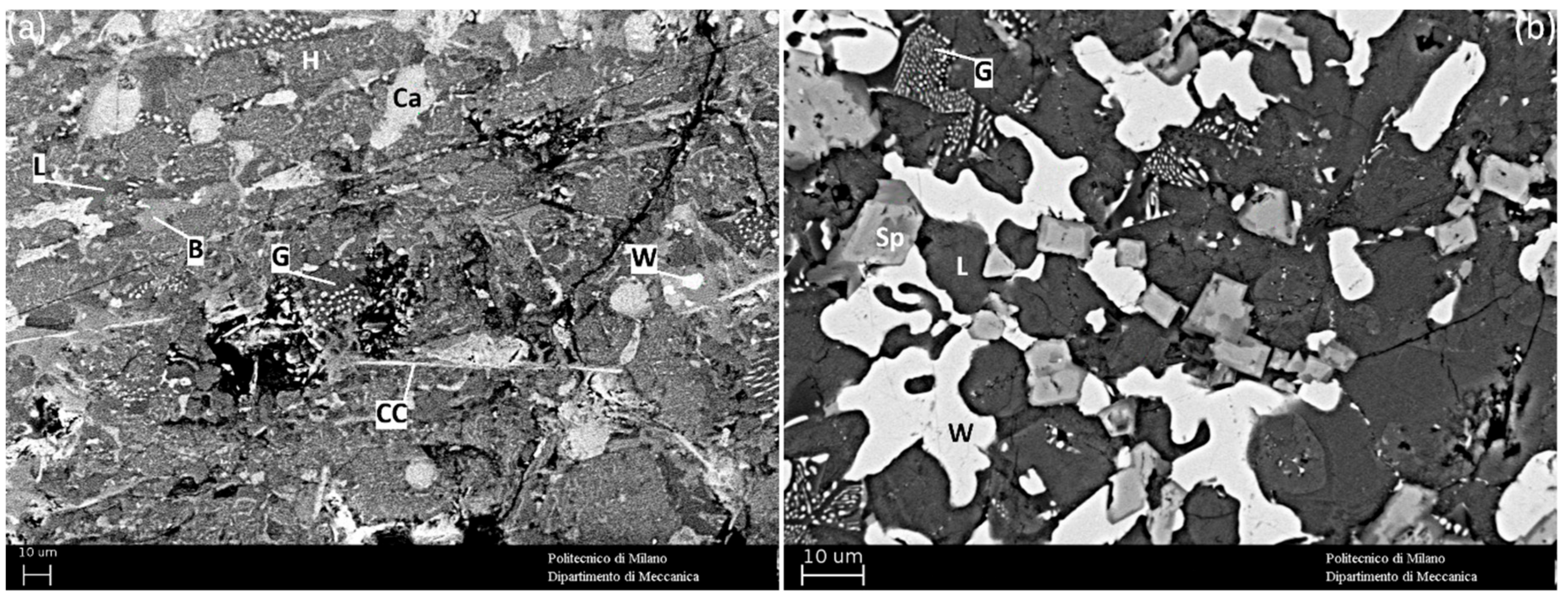
XRD analysis highlighted significant differences between the as-received and the modified slag (Figure 3). The as-cast slag mainly consisted of five crystalline phases: wustite (W mark), brownmillerite (B mark in Figure 4), hatrurite (3CaO·SiO2) (H mark in Figure 4), and larnite (L mark), and calcium chromite (CC mark in Figure 4) was also detected. Calcium silicates (3CaO·SiO2, 2CaO·SiO2) have well-known hydraulic properties, and the high concentration of heavy metals dissolved in such phases (0.24 atom % of Ba; 0.09 atom % of V in H; 0.22 atom % of Ba and 0.50 atom % of V in L) make them potential responsible for Ba and V leaching [24]. Brownmillerite also belongs to the main constituents of the cement and possesses modest hydraulic properties that could heighten the leaching of Ba and Cr dissolved in this phase (0.15 atom % of Ba; 9–10 atom % of Cr) [25,26]. The role of calcium chromite in Cr leaching is also well known [27].
The quartz injection contributed to complexify the exceeding CaO, avoiding the formation of free lime and hatrurite. In particular, free lime was reduced to about 75 wt % with respect to the as-received slag. Moreover, the chemical correction contributed to hinder the formation of CaO·Cr2O3 that was detected in the as-received samples. Although a significant amount of quartz was injected in the slag, the crystallographic analysis still pointed out a large residual larnite fraction and a very low gehlenite amount. A residual brownmillerite fraction was also detected. However, part of the toxic elements subjected to leaching were incorporated in stable structures (Cr–Mg-spinels and gehlenite), also decreasing those dissolved in larnite (0.10–0.13 atom % of V and 0.10–0.30 atom % of Ba); hence, improving the retaining behavior of the slag.
Although the treated samples were featured by different granulometry and by different amounts of the added quartz (Table 2), they pointed out very similar crystallographic composition and microstructure. In particular, the lower the silica addition, the higher the gehlenite fraction. On the other hand, high amounts of quartz contributed to the sensible reduction of the brownmillerite fraction. Although favorable in its chemical composition, the C2Ma sample microstructure differed from the expected one. Even with the highest quartz correction, the microstructure manifested a higher mayenite (Ca12Al14O33) dispersion than the other modified samples. Mayenite is a clear indication that the slag only partially reacted with the injected quartz. Generally, if calcium aluminates are within the slag, a low amount of SiO2-containing material is enough to form high gehlenite fraction. This is because the reaction between calcium aluminates and calcium silicates is thermodynamically possible at the tapping temperatures of the slag [28,29]. If mayenite is still detectable after stabilization treatment, this means that the added quartz could not succeed in combining with it. This is due to a partial interaction between slag and stabilizer. In other words, the slag became cold before complete reacting with the quartz. This happens only in slag-pit-tapped slag, where the contact between slag and stabilizer occurs only in the path from slag-door to pit floor. When the slag reaches the floor, it cools so fast that it hinders any further reactions with the stabilizer.
Leaching test results were in agreement with the mineralogical features of the investigated slag (Table 4). After the SiO2 correction, the samples characterized by major gehlenite content pointed out a low barium leaching (C1Mc and C2Mb). On the other hand, the sample featured by low brownmillerite amount showed a reduced Cr leaching (C1Ma, C1Mb, C1Mc, C2Ma) compared with the as-received samples. One possible explanation relates to the layout of the stabilization system. The experimental evidence demonstrated that quartz could react with the slag but it did not have enough time to complete the reactions. The decrease in hatrurite and the free lime fraction was glaring evidence that the quartz dissolved and reacted with the molten slag. However, the quartz spray had a drawback—it increased the slag cooling rate. This aspect, associated with the rapid cooling induced by the contact with slag-pit floor, contributed to the slowing of the slag microstructure evolution, hindering the completion of diffusive reactions. In addition, over 15 wt % of quartz worsened the slag behavior against the pollutant release—the higher the sand flow, the higher the induced slag cooling. This implied a heterogeneous slag microstructure, characterized by areas featured by the same morphology and by the same structural constituents present in the as-received slag (Figure 5). For instance, in sample C2Ma (20 wt % of injected quartz), a portion of slag far from the impingement area of the quartz stream had the same microstructure as the as-received slag (Figure 5a). A portion of slag solidified close to the impingement area was found to have slightly higher amount of gehlenite, good coarsening of spinel, and absence of brownmillerite (Figure 5b). This influenced the leaching of toxic elements—sample (a) leached 3.14 mg/L of Ba and 75 μg/L of Cr (higher than the average leaching of the whole sample). On the contrary, sample (b) leached 2.15 mg/L of Ba and 25.6 μg/L of Cr (less than the average leaching of the whole sample).
Four samples in batch D slag were investigated. By the positioning of the average chemical composition on the ternary diagrams in Figure 2, the increase in SiO2 and a slight dilution of CaO and Al2O3 concentrations after quartz correction can be observed. The analysis of the modified slag showed a slight deviation of the SiO2 reached after injection (±2%). This result can be interpreted as a non-complete homogenization of the slag after the treatment, probably due to both the injection methods and the tapping technique. In fact, the absence of a slag pot does not allow for the collection and stirring of the slag with the stabilizer, leading to a reduction of quartz dissolution inside the slag. In particular, after the quartz correction, the modified slag chemical composition only approached the regions considered as safe (gehlenite and olivine). Thus, the addition was not enough to bring the slag to the desired conditions. In particular, undissolved quartz crystals were identified in some coarse granules of slag. This was a clear index that the efficiency of quartz addition without a pot was largely less than with a pot collector.
From a crystallographic point of view, the modified slag (sample DM) did not differ significantly from the as-received form (sample D) (Figure 3). The identified phases within all the samples were larnite, wustite, mayenite, and hercynite (an iron–aluminum spinel with composition FeAl2O4). Peaks associated with brownmillerite were also identified in both as-received and stabilized slag, whereas only few reflections associated with gehlenite were found in the treated slag. This means that this last phase was in amounts too small to assure enough hydrophobicity against water. This was better highlighted in SEM pictures, where it was very hard to observe gehlenite grains within the microstructure (Figure 4). Once again, the residual presence of mayenite in the modified samples was a clear index of a lack of reaction between quartz and molten slag, supporting the main conclusion that the stabilization treatment can only really be effective if the slag is collected in a pot.
Regarding the toxic metals under monitoring, barium was mainly distributed in mayenite (0.4–0.5 atom %), larnite (0.45–0.55 atom %), and brownmillerite (0.6–0.7 atom %), phases that tended to hydrate and release the aforementioned element. In particular, mayenite had faster reactivity with water than larnite and brownmillerite, and this can explain the high leaching of Ba both in as-received and modified slag. Traces of barium were also detected in wustite, probably associated with the consistent fraction of CaO that characterizes this phase. Vanadium was bound mostly in spinels (0.15 atom %) and wustite (0.15–0.2 atom %), and traces could also be also found in larnite (0.15 atom %) and brownmillerite (0.4–0.5 atom %). Given the small fraction of chromium spinel and the known stability of wustite, this element cannot be easily leached (Table 4). Chromium was totally bound in the form of spinel, and therefore no leaching was observed, mainly because the spinels were in a limited fraction.
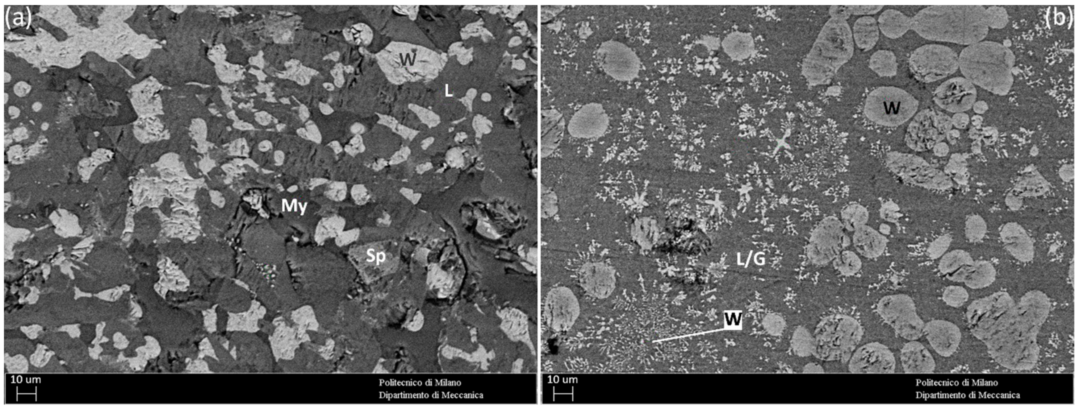
Two other different samples were collected after the complete solidification of the slag in the pit. The slag identified as “DMu” represented the last layer of slag deposited in the pit and, thus, the first portion of solidified slag. It was formed by a continuous larnite matrix in which wustite, mayenite, and a small fraction of chrome spinels were dispersed (Figure 3, Figure 6a). Gehlenite was not identified. This slag was practically similar to the as-received slag, even if it underwent the stabilization treatment. This means that the absence of an intimate contact between slag and stabilizer for a prolongated time cannot induce the crystallographic transformations needed to inhibit the metal leaching.
The slag identified as “DMd” represented the first layer of slag deposited in the pit and, thus, the last portion of solidified slag. The effect of the slow solidification can be recognized in the crystallographic arrangement and in the microstructure of the slag—a more homogeneous matrix can be identified in which strong dendritic wustite is dispersed (Figure 3, Figure 6b). This wustite was also enriched in Mg and Cr with respect to the other samples—it is probable that the maintenance in the liquid phase for a long time allowed a redistribution of the elements within the various phases. In addition, this was the only sample where gehlenite could be well identified both from XRD and SEM analysis. This aspect was certainly associated with the fact that by keeping the slag liquid for a longer time, reactions between calcium silicate, calcium aluminate, and injected quartz can lead to the formation of gehlenite. This higher amount of gehlenite contributed to the slight reduction of Ba concentration in the leachate (Table 4).

3.3. Discussion

The obtained results demonstrated the applicability and the efficacy of the stabilization treatment by quartz addition, although in some cases the modified slag still had leaching problems. The quartz addition stimulated the microstructural transformation, leading the formation of non-hydraulic phases (i.e., gehlenite) able to retain the pollutant elements and reduce the slag solubility. The analysis performed on the four slag groups indicated that a slag characterized by high FeO content (>30 wt %) and a Al2O3/MgO ratio approximately equal to 4–4.5 reacted easily with the quartz to form homogeneous gehlenite matrix (as happened in samples A). Such a phase assures a reliable stability, also the case for fine powder slag, as demonstrated in [17]. In this situation, a small amount of quartz (8–12 wt %) was enough to transform the calcium silicate matrix into a gehlenite matrix. When Al2O3, Fe2O3, SiO2, and CaO coexist in liquid phase, gehlenite and brownmillerite were likely to form, due to a lower free energy of formation with respect to calcium silicates, calcium aluminates, and calcium ferrites. If alumina are saturated by CaO and SiO2, brownmillerite cannot form [29]. However, gehlenite cannot easily form from the direct reaction between xCaO·yAl2O3 and xCaO·ySiO2 because it is not thermodynamically favorable. This behavior is also confirmed by the clinker chemistry. Indeed, gehlenite never forms during the roasting of clinker raw materials [26]. This is the reason why a gehlenite promoter (i.e., SiO2) must be added from the outside of the slag. In fact, only direct reaction between xCaO·yAl2O3 or 4CaO·Al2O3·Fe2O3 and SiO2 is thermodynamically favored. In the presence of calcium aluminates, a relatively small amount of SiO2 is enough to form a large amount of gehlenite [30]. If calcium aluminates are not within the slag, the addition of a SiO2-beraing material helps to expel the Al2O3 in Al2O3-rich calcium silicate (such as those present in the most of the EAF slag), again giving the conditions for gehlenite formation [29].
On the other hand, slag characterized by low FeO concentration did not easily form gehlenite, especially if the ratio Al2O3/MgO was lower or at least equal to 1 (samples B, C, D). High MgO content seemed to favor the reaction among MgO, CaO, and SiO2 to form merwinite. Gehlenite formation seemed to be limited, as MgO has higher reactivity with SiO2 than Al2O3. In addition, when the quartz cannot properly react with the slag (i.e., slag-pit tapping), the only effect of chemical correction was to convert part of the bredigite or the hatrurite to larnite, without a significant improvement of water reactivity reduction of the slag. Thus, the formation of merwinite was less efficient than the formation of gehlenite in terms of slag stabilization. This was independent from the tapping method, even though the slag-pit tapping led to a higher residual of unreacted Ca2SiO4 due to a lower interaction between slag and stabilizer. In addition, as reported by Engström [14], the rate of merwinite dissolution at high pH (from 7 to 10) is low but not negligible. This means that the solubility of merwinite in a merwinite-based slag system can partly explain some of the leaching that occurs from these slags.
Thanks to the comparison among different steel slags, the role of mayenite in Ba leaching is clarified (in [17,31] mayenite was only suspected to leach Ba). Mayenite, along with Ca2SiO4, not only was responsible for Ba leaching, but also could be used as a marker of mixing efficiency between slag and stabilizer. If mayenite can be detected in final stabilized slag, the efficacy of stabilization treatment will be partially reached, associated with a high leaching risk of the toxic metals dissolved within [14].
All the steelworks adopting slag-pot tapping reached better results in terms of slag modification. The microstructural transformation affected the whole amount of treated slag, and its chemical, physical, and mechanical properties were constant along the whole treated mass. These slags were characterized by a homogeneous microstructure, a very limited phase distribution, and small morphology differences.
For a pit-tapped slag, the stabilization treatment did not promote the expected microstructural transformation. Slag treated in slag-pit manifested high heterogeneity. Even if the quartz was completely dissolved in the fluid slag mass, a low gehlenite amount was formed and the slag resulted in a larnite matrix. The presence of mayenite in the treated slag was a clear index of the uncompleted reaction between slag and stabilizer.
Slag-pit favored the layering of the slag, inducing completely different behaviors from top to bottom of the treated pile. The last solidified layer behaved practically as an as-received slag (i.e., with high leaching), whereas the first layer (i.e., the first came in contact with the floor), remaining hot for longer time, showed a higher degree of microstructural transformation, not comparable with slag treated in a pot. This latter aspect was due to the fast cooling induced by the contact between slag and floor. Being that the slag partially solidified when it touched the pit floor, the reaction between slag and stabilizer cannot further proceed, even when the next amount of tapped slag covered and reheat this first layer.
The slag-pot played a key-role on the treatment efficiency, as it produced a stirring effect and maintained the slag liquid far enough to permit the completion of diffusive reaction among the different oxide species. Mass stirring should be always realized to favor the dissolution and the reaction among the different chemical species because the dissolution rate of a solid substance in a fluid mass is controlled by the mass transport [28].

4. Conclusions

Chemical composition correction with quartz outside the electric arc furnace was proven to be a valid method to modify a slag in order to reduce the risk of toxic metal leaching. However, the efficacy of such a treatment is strongly dependent on the tapping method of the slag.
  • The slag-pot promoted the stirring effect during the pot filling and the prolonged resident time contributed to homogenize the slag structure, allowing the fulfilling of diffusive reactions. This led to a homogeneous microstructure and, as a consequence, to constant mechanical, physical, and chemical properties.
  • The slag-pit tapping, instead, reduced the contact time between slag and stabilizer, leading to layering and, consequently, high slag heterogeneity in terms of chemical, crystallographic, and microstructural properties that resulted in high levels of toxic metal leaching.
In conclusion, if an EAF slag needs to be chemically stabilized for an effective recycling without any risk of toxic metal leaching, slag-pot tapping is mandatory to fulfill a full transformation of the microstructure.

Author Contributions

Conceptualization, C.M. and D.M.; methodology, D.M.; investigation, D.M.; resources, A.G.; writing—original draft preparation, D.M.; writing—review and editing, S.B.; supervision, C.M.

Funding

This research received no external funding.

Acknowledgments

Authors would like to thank Eng. Umberto Di Landro (Dilab, Crema (CR)) for ICP-MS analysis, and Gwenn Le Saout and the Centre des Materiaux des Mines d’Alès (C2MA) (Ecole des Mines d’Alès) for XRD analysis.

Conflicts of Interest

The authors declare no conflict of interest.

References

  1. Rina Services. Registed Products Certified by Rina Services S.p.A. in According to Directive 89/106/CEE (CPD) & Regulation EU N. 305/2011 (CPR) 2019; Rina S.p.A.: Milano, Italy, 2019. Available online: https://shared.rina.org/SCresources/Documents/list_certificates_construction_products_it.pdf?Mobile=1&Source=%252FSCresources%252F_layouts%252F15%252Fmobile%252Fviewa.aspx%253FList%253Dfb565f66-87e0-4120-9dc6-999c8396f205%2526View%253D6f0bc351-6418-43ed-8bed-a91d25e8c3f7%252 (accessed on 13 November 2019).
  2. Barocci, A.; Luzzari, G.; Facchin, M. Procedure operative per la produzione di inerte artificiale in luogo di scoria nera. Metall. Ital. 2014, 106, 37–41. [Google Scholar]
  3. Mazzucchelli, C.; Tolettini, E. Marcatura CE sottoprodotto GREENSTONE 2+. Verde Feral. 2014, IX, 14–15. [Google Scholar]
  4. Acciaierie Bertoli Safau Ecogravel® Plants, Valorizzazione Delle Scorie da EAF: Una Grande Opportunità. Available online: http://www.absacciai.it/#/nav/Sito_WEB_Page_27 (accessed on 15 October 2019).
  5. European Slag Association Euroslag Statistics. Available online: http://www.euroslag.org/products/statistics/ (accessed on 13 November 2019).
  6. Kühn, M.; Drissen, P.; Schrey, H. Treatment of liquid steel slags. In Proceedings of the 2nd European Slag Conference (II EUROSLAG), Düsseldorf, Germany, 9–11 October 2000; pp. 123–135. [Google Scholar]
  7. Kasina, M.; Michalik, M. Characterization of convertor slag in terms of slag instability. In Proceedings of the 1st European Mineralogical Conference, Frankfurt, Germany, 2–6 September 2012; Volume 1, p. 2012. [Google Scholar]
  8. Lee, Y. Study of Volume Stability and Recycling of BOF Slag at China Steel. In Proceedings of the 7th European Slag Conference (EUROSLAG 2013), Ijmuiden, The Netherlands, 9–11 October 2013; pp. 17–26. [Google Scholar]
  9. Epstein, H.; Iacobescu, R.I.; Pontikes, Y.; Malfliet, A.; Machiels, L.; Jones, P.T.; Blanpain, P.T. Stabilization of CaO-SiO2-MgO (CSM) Slags by Recycled Alumina. In Proceedings of the 7th European Slag Conference, Ijmuiden, The Netherlands, 9–11 October 2013; Volume 6, pp. 111–120. [Google Scholar]
  10. Mombelli, D.; Mapelli, C.; Barella, S.; Di Cecca, C.; Le Saout, G.; Garcia-Diaz, E. The effect of chemical composition on the leaching behaviour of electric arc furnace (EAF) carbon steel slag during a standard leaching test. J. Environ. Chem. Eng. 2016, 4, 1050–1060. [Google Scholar] [CrossRef]
  11. Erdmann, R.; Kesseler, K.; Mudersbach, D.; Kühn, M. A new product: “Highly valuable slag from the OxyCup”. In Proceedings of the 5th European Slag Conference (V EUROSLAG), Luxembourg, 19–21 September 2007; pp. 89–106. [Google Scholar]
  12. Kühn, M.; Mudersbach, D.; Baena Liberato, J.M.; De Angelis, V.; Capodilupo, D.; de Fries, U. Chrome immobilisation in EAF slags from high-alloy steelmaking: Development of a slag treatment process. EUR 2006, 22077, 1–96. [Google Scholar]
  13. Mudersbach, D.; Kühn, M.; Geiseler, J.; Koch, K. Chrome Immobilisation in EAF-Slags from High-alloy Steelmaking: Tests at FEhS-Institute and Development of an Operational Slag Treatment Process. In Proceedings of the 1st Interntational Slag Valorisation Symposium, Leuven, Belgium, 6–7 April 2009; pp. 101–110. [Google Scholar]
  14. Engström, F.; Adolfsson, D.; Samuelsson, C.; Sandström, Å.; Björkman, B. A study of the solubility of pure slag minerals. Miner. Eng. 2013, 41, 46–52. [Google Scholar] [CrossRef]
  15. Strandkvist, I.; Björkman, B.; Engström, F. Synthesis and dissolution of slag minerals—A study of β-dicalcium silicate, pseudowollastonite and monticellite. Can. Metall. Q. 2015, 54, 446–454. [Google Scholar] [CrossRef]
  16. Raiger, T.; Mudersbach, D.; Markus, H.P.; Algermissen, D.; Aicher, M.; Gmbh, U.; Gmbh, L. Factors of influence during and after the electric steel making process: Characterization and optimization of electric arc furnace slag. In Proceedings of the 8th European Slag Conference, Linz, Austria, 21–23 October 2015; pp. 1–10. [Google Scholar]
  17. Mombelli, D.; Mapelli, C.; Barella, S.; Gruttadauria, A.; Le Saout, G.; Garcia-diaz, E. The efficiency of quartz addition on electric arc furnace (EAF) carbon steel slag stability. J. Hazard. Mater. 2014, 279, 586–596. [Google Scholar] [CrossRef] [PubMed]
  18. Primavera, A.; Pontoni, L.; Mombelli, D.; Barella, S.; Mapelli, C. EAF Slag Treatment for Inert Materials ’ Production. J. Sustain. Metall. 2016, 2, 3–12. [Google Scholar] [CrossRef]
  19. Ministero dell’Ambiente. Definition of the Criteria for Waste Acceptance at Landfills; Gazzetta Ufficiale Serie Generale n.201 del 30-08-2005; Ministero dell’Ambiente: Roma, Italy, 2005. [Google Scholar]
  20. Ministero dell’Ambiente. Identification of Nonhazardous Waste Subject to Simplified Recovery Procedures; Gazzetta Ufficiale Serie Generale n.115 del 19-05-2006; Ministero dell’Ambiente: Roma, Italy, 2006. [Google Scholar]
  21. Mombelli, D.; Mapelli, C.; Di Cecca, C.; Barella, S.; Gruttadauria, A. Scorie da forno elettrico ad arco: Studio sui meccanismi di rilascio e trattamenti di stabilizzazione. Metall. Ital. 2016, 10, 5–17. [Google Scholar]
  22. Klemm, W.; Skalny, J. Selective dissolution of clinker minerals and its applications. Martin Mariietta Lab. 1977, 77, 1–30. [Google Scholar]
  23. Mombelli, D.; Barella, S.; Gruttadauria, A.; Mapelli, C.; Le Saout, G.; Garcia-Diaz, E. Effects of basicity and mesh on Cr leaching of EAF carbon steel slag. Appl. Sci. 2018, 9, 121. [Google Scholar] [CrossRef]
  24. Mombelli, D.; Mapelli, C.; Gruttadauria, A.; Baldizzone, C.; Magni, F.; Levrangi, P.L.; Simone, P. Analisys of electric arc furnace slag. Steel Res. Int. 2012, 83, 1012–1019. [Google Scholar] [CrossRef]
  25. Odler, I. Hydration, Setting and Hardening of Portland Cement. In Lea’s Chemistry of Cement and Concrete; Heinemann, B., Ed.; Elsevier: Oxford, UK, 2003; pp. 241–297. ISBN 9780750662567. [Google Scholar]
  26. Taylor, H.F.W. Cement Chemistry, 2nd ed.; Thomas Telford Publishing: London, UK, 1997; ISBN 0-7277-3945-X. [Google Scholar]
  27. Ylipekkala, J. Quality Management of Chromium Containing Steel Slags from Melt Phase to Cooling. Master’s Thesis, Lulea University of Technology, Luleå, Sweden, 2005. [Google Scholar]
  28. Mukai, K.; Ishikawa, T. Surface Tension Measurements on Liquid Slags in CaO-SiO2, CaO-Al2O3 and CaO-Al2O3-SiO2 Systems by a Pendant Drop Method. J. Jpn. Inst. Met. Japan Inst. Met. Mater. 1981, 45, 147–154. [Google Scholar] [CrossRef]
  29. Zhu, Z.; Jiang, T.; Li, G.; Guo, Y.; Yang, Y. Thermodynamics of Reactions Among Al2O3, CaO, SiO2 and Fe2O3 During Roasting Processes. In Thermodynamics—Interaction Studies—Solids, Liquids and Gases; InTech: London, UK, 2011; pp. 825–838. [Google Scholar]
  30. West, A.R. Solid State Chemistry and Its Applications; John Wiley & Sons Ltd.: Hoboken, NJ, USA, 1984; ISBN 0471903779. [Google Scholar]
  31. Mombelli, D.; Mapelli, C.; Barella, S.; Di Cecca, C.; Le Saout, G.; Garcia-Diaz, E. The effect of microstructure on the leaching behaviour of electric arc furnace (EAF) carbon steel slag. Process Saf. Environ. Prot. 2016, 102, 810–821. [Google Scholar] [CrossRef] [Green Version]
Figure 1. Steel slag production and utilization (in Mt/y) from 2000 to 2016 in European Union (data from Euroslag) [5]. EAF-C: electric arc furnace carbon steel slag.
Minerals 09 00706 g001
Figure 2. Ternary diagrams of the positioning of analyzed slag. Red areas: probable toxic metal leaching; green areas: probable toxic metal retaining [10].
Minerals 09 00706 g002
Figure 3. XRD patterns detailing 25° to 50° 2θ of analyzed slag.
Minerals 09 00706 g003
Figure 4. SEM-BSE microstructure comparison before and after stabilization treatment. B = brownmillerite, Br = bredigite, CC = calcium-chromite, G = gehlenite, H = hatrurite, L = larnite, M = merwinite, My = mayenite, Pr = perovskite, Sp = Mg–Cr-spinel, W = wustite.
Minerals 09 00706 g004
Figure 5. SEM-BSE pictures of two areas of sample C2Ma: (a) far from the impingement area and (b) close to the impingement area. B = brownmillerite, Ca = free lime, CC = calcium-chromite, G = gehlenite, H = hatrurite, L = larnite, Sp = Mg–Cr-spinel, W = wustite.
Minerals 09 00706 g005
Figure 6. SEM-BSE microstructure of DMu (a) and DMd (b) samples.
Minerals 09 00706 g006
Table 1. Batching and tapping methods of samples.
Group IDNumber of SamplesProductionTapping MethodStabilizer
A4Reinforcing bar steelSlag potQuartz
B4Quality steelSlag potSiliceous sand
C7Quality steelSlag pitQuartz
D4Quality steelSlag pitQuartz
Table 2. Experimental plan for stabilizer addition in group C slag.
SampleC1MaC1MbC1McC2MaC2Mb
Particle size (mm)1–31–31–21–21–3
Stabilizer (wt %)1212.5132013
Table 3. ED-XRF chemical composition of the investigated slag samples (wt %).
SampleCaOSiO2Al2O3MgOCr2O3V2O5BaOFeOxMnOTiO2P2O5SK2ONa2O
Batch A
A119.8115.4512.052.994.280.150.0636.876.410.770.500.270.210.13
A1M17.7320.8912.052.492.870.140.0936.125.820.810.470.190.180.10
A223.2613.0310.202.372.840.130.1139.106.960.630.620.550.060.13
A2M16.6121.4210.272.303.480.160.0737.766.170.800.420.160.260.09
Batch B
B29.6814.449.713.251.820.15-20.027.040.950.550.230.090.08
BM24.8223.019.6512.381.590.17-19.886.351.030.500.170.080.07
Batch C
C139.8316.966.4510.292.980.220.4015.775.860.460.480.570.000.02
C1Ma34.2416.256.013.442.050.200.5728.986.380.440.500.20--
C1Mb30.7223.096.003.362.050.170.5126.785.530.360.420.16--
C1Mc29.8620.966.245.113.060.20-26.196.740.490.400.490.090.02
C242.7215.117.358.452.640.230.3016.275.610.490.380.620.000.03
C2Ma28.2329.755.273.331.690.160.5024.265.070.360.410.16--
C2Mb29.7418.786.636.772.690.21-26.067.550.500.410.500.060.02
Batch D
D28.4113.1213.5513.071.940.18-20.636.841.100.500.400.000.08
DM29.2520.8911.588.101.550.16-20.755.611.070.610.140.050.07
DMu25.8010.7814.199.802.350.18-26.688.190.990.410.360.010.09
DMd21.6416.649.3417.382.060.17-23.367.570.930.400.240.050.07
Table 4. Average values of leaching tests resulting in the four batches of investigated slag (bold red values are exceeding the limits). Standard deviation is within 10% of the measurement.
SampleBa
(mg/L)
Cr
(μg/L)
V
(μg/L)
pH
A10.68-136.0010.90
A1M0.80-48.0010.70
A24.97--11.40
A2M0.14-33.0010.60
B9.81-50.0011.59
BM0.28-51.0011.83
C12.3070.00-12.20
C1Ma1.8445.5814.5712.20
C1Mb2.6530.33-12.20
C1Mc0.2634.1552.9311.73
C21.41170.00-12.20
C2Ma2.8731.18-12.20
C2Mb0.4361.8334.4811.88
D7.2030.0015.0011.50
DM3.603.003.0011.28
DMu6.2010.0010.0011.50
DMd3.4710.0010.0011.10
Limits<1<50<2505.5–12

