An Innovative Method for Placement of Gangue Backfilling Material in Steep Underground Coal Mines
by
 , , , and
Yanchun Yin
1,2 ,
,
Tongbin Zhao
1,2,
Yubao Zhang
1,2,3,*,
Yunliang Tan
1,2,
Yue Qiu
1,2,*,
Abbas Taheri
3 and
Yuan Jing
4 1
State Key Laboratory of Mining Disaster Prevention and Control Co-founded by Shandong Province and the Ministry of Science and Technology, Shandong University of Science and Technology, Qingdao 266590, China
2
College of Mining and Safety Engineering, Shandong University of Science and Technology, Qingdao 266590, China
3
School of Civil, Environmental and Mining Engineering, The University of Adelaide, Adelaide, SA 5005, Australia
4
Beijing Haohua Energy Resourse Co., Ltd., Beijing 102304, China
*
Authors to whom correspondence should be addressed.
Minerals 2019, 9(2), 107; https://doi.org/10.3390/min9020107
Submission received: 17 January 2019
/
Revised: 7 February 2019
/
Accepted: 11 February 2019
/
Published: 13 February 2019
(This article belongs to the Special Issue Backfilling Materials for Underground Mining)
Abstract
:Using gangue backfilling in underground coal mining not only controls the roof deformation in the gob area but also reduces the amount of mining waste rock. However, due to the limitations of the complicated engineering conditions, backfilling mining in the steep coal seam is not widely applied. In this study, a long-distance backfilling technology with a scraper winch for a steep coal seam was proposed and applied in a flexible shield supporting working face in Datai Mine, Beijing. Aiming at the problem of the decreasing backfilling ratio in field practice, numerical simulation was carried out to research the moving law of gangue in the goaf. The gangue mainly experienced four stages: gangue landslide stage, small-scale subsidence stage, funnel-shaped subsidence stage, and large-scale subsidence stage. The moving area of the gangue could be divided into five areas including a motionless area, a landslide area, a subsidence area, a funnel-shaped subsidence area, and a to-be-backfilled area. With the increase of the inclined length of the working face, the moving time of the gangue increased gradually. Based on the simulation results, the scheme of backfilling and mining in Datai Mine was optimized, for which the inclined length of the working face was shortened, and a higher backfilling ratio was obtained.
1. Introduction
Coal resources in China have diverse distribution and development characteristics. Large dip or steep coal seams account for around 15% to 20% of the total reserves in China. Specifically, in western China, more than 50% of coal mining occurs in inclined or steeply inclined coal seams [1,2,3]. In recent years, with the gradual depletion of the coal resources in the eastern and western parts of China, many mining regions have begun to mine steep coal seams [4,5,6,7,8,9,10,11]. Therefore, it is crucial to develop mining methods that are suitable for steep coal seams to maintain sustainable and cost-effective development of underground energy.
Fully mechanized mining is very difficult for a steep coal seam with a large inclination angle and a hard roof [12]. As a simple and easy mining method, a flexible shield supporting mining method has been widely used in many steep coal seam mining operations. However, when mining under a hard roof by the caving method, a large area of the roof can hang, which will lead to a collapse of integrity and will have a strong impact on the working face [13,14,15,16,17]. To control the coal seam roof effectively, gangue backfilling is used to support the roof [18,19,20,21,22,23]. Different from the cemented paste backfilling or solid waste backfilling in gently inclined coal seams and flat seams [24,25,26,27,28], the commonly used backfilling mining methods include the longwall backfilling mining method on the strike with a pseudo-inclined working face, the longwall obliquity backfilling mining method with strips, and the backfilling mining method of the inverted step working face. Gangue backfill materials are placed in underground mines with steep coal seams with self-movement. However, there are still many problems associated with the practice of backfilling mining in steep coal seams, which makes the backfilling uneconomical. Moreover, the addition of the backfilling technology affects the normal operation of the mining face, and the production efficiency is low, which limits the further application of the gangue backfilling mining technology.
One of the key problems in placing backfill in underground mining is the limited knowledge on the backfilling patterns in steep coal seams after extraction. Properties of cemented aggregates have been widely investigated [29,30,31]. Li et al. [32,33] studied the particle-crushing and acoustic-emission characteristics of the crushed gangues and loose gangues under compressive loading and found that the crushing ratio was highly correlated with the acoustic-emission signals. Li and Ju [34] assessed the effect of binders on the compaction characteristic of gangues and found that fly ash or lime was a suitable binder for modifying the backfilling materials. However, there has been little research on the backfilling process in the goaf of steep coal seams.
In this paper, the gangue backfilling technology of Datai Mine in Beijing is investigated. Aiming at the problems associated with backfilling practice, a numerical simulation is carried out to investigate the moving law and backfilling characteristics of gangue. Based on the simulation results, the backfilling and mining scheme is optimized.
2. Gangue Backfilling Test in Datai Coal Mine
2.1. Project Introduction
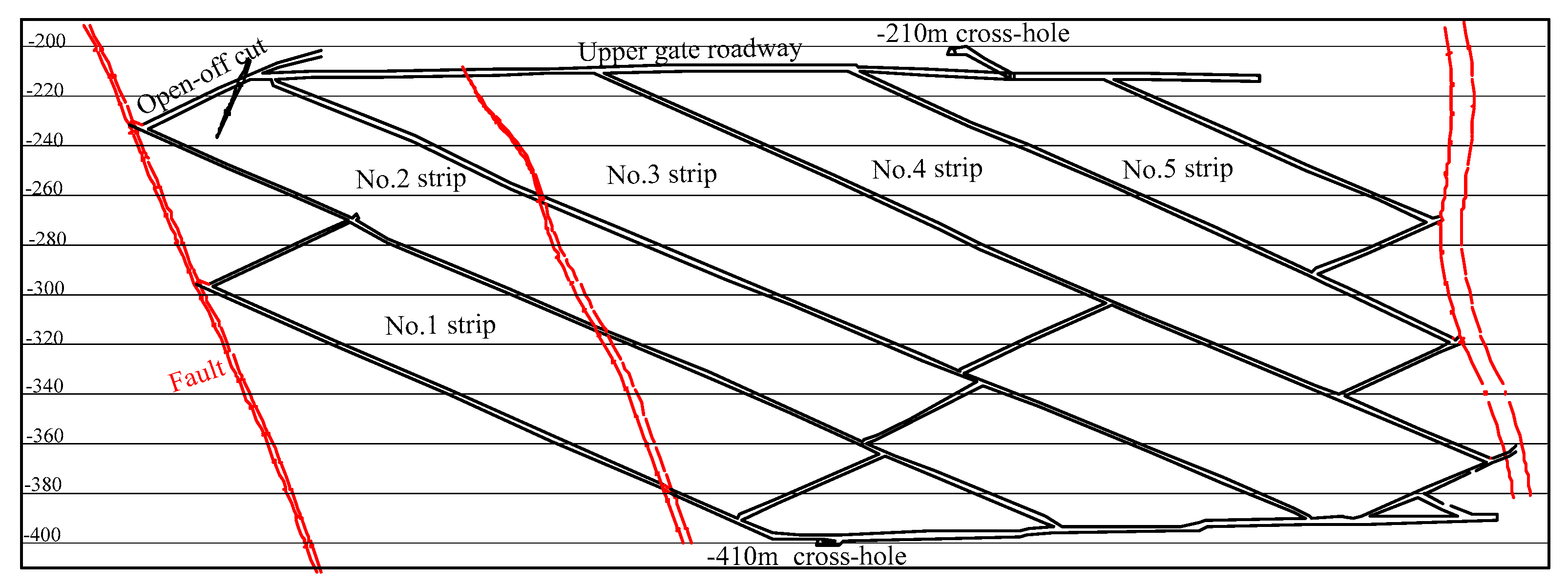
Datai Coal Mine is located at the west of Beijing, China, in a mountainous area. The mining area of the No. 845 working face in Datai Coal Mine has an upper boundary elevation of −210 m and a lower boundary elevation of −407 m. There are many faults in the working face. The average strike length and the inclined length of the working face are 1130 m and 200 m, respectively. The coal seam is a monocline structure that belonged to the steep coal seam. The maximum dip angle is 76°, the minimum dip angle is 60°, and the average dip angle is 67°. The coal seam thickness is 1.23 m to 1.9 m, and the average coal thickness is 1.7 m. The lithology of the coal seam and overlaying and underlying strata are listed in Table 1.
The 845 working face adopted the slope flexible shield supporting method, which was arranged with the No. 1–5 strips. The roadways were arranged at angles of 23° to 25° along the bow pseudo-incline and extended from west to east. The corresponding working face layout is shown in Figure 1.
2.2. Backfilling Technology and System Layout
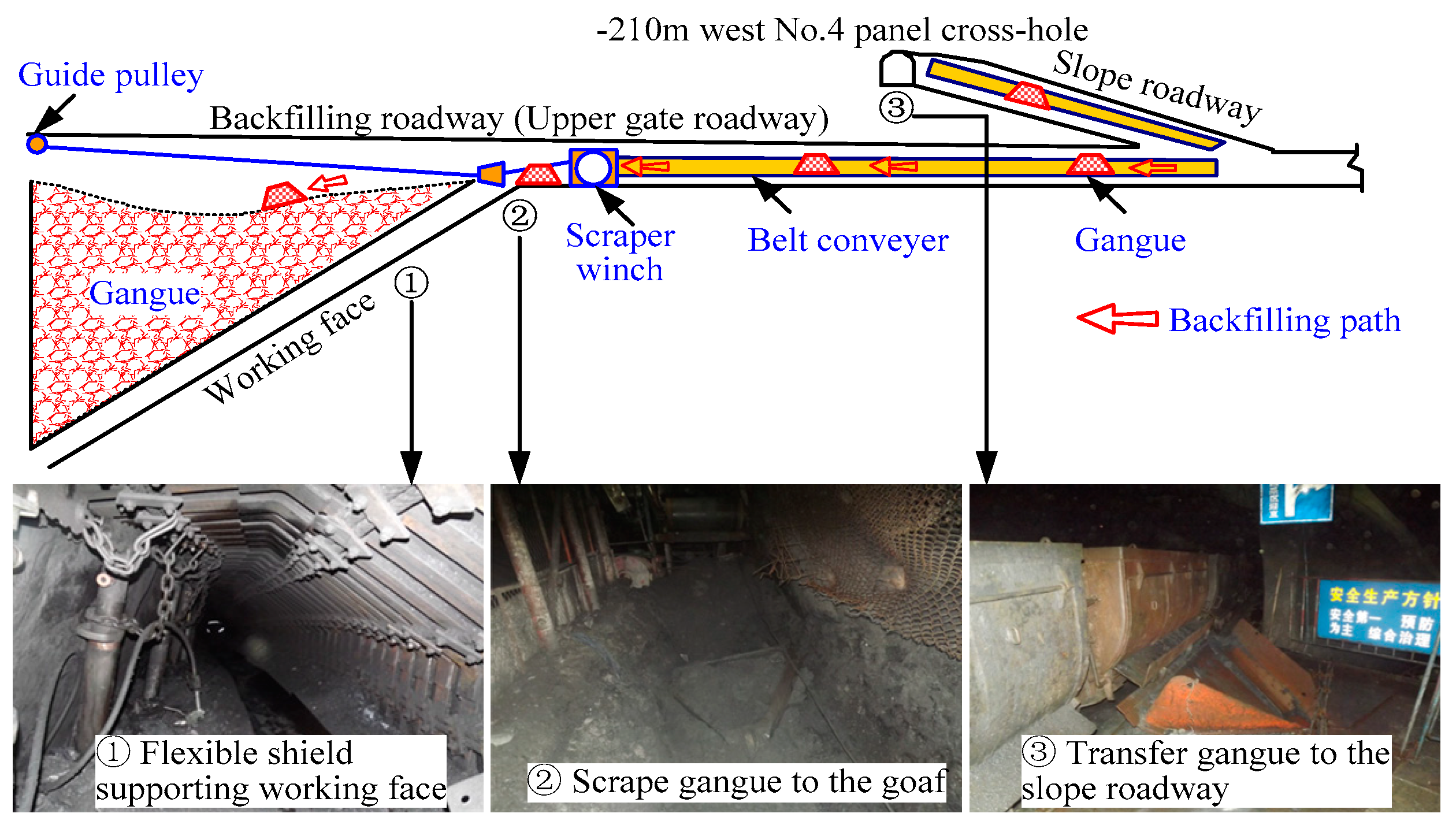
Based on the geological and mining conditions, a long-distance gangue backfilling technology with a scraper winch was designed and used in the No. 845 working face, as shown in Figure 2. During the process of mining and backfilling, the gangue at the various mining levels was transported to the upper gate roadway and the backfilling region by a belt conveyor. A scraper winch was utilized to scrape the gangue to the goaf, and the gangue backfilled the goaf under the self-weight. When the working face advanced a certain distance (it was 100 m in 845 working face), the scrape winch and guide pulley should be moved forward in time. According to the performance of the winch and the arrangement of the guide pulley, the backfilling system can be used to effectively backfill the region up to 100 m in the goaf. Aiming to improve the moving property, gangue was crushed into small particles with a size range of 5 cm to 15 cm, and its average angle of repose is 35°.
2.3. Problems in Backfilling Practice
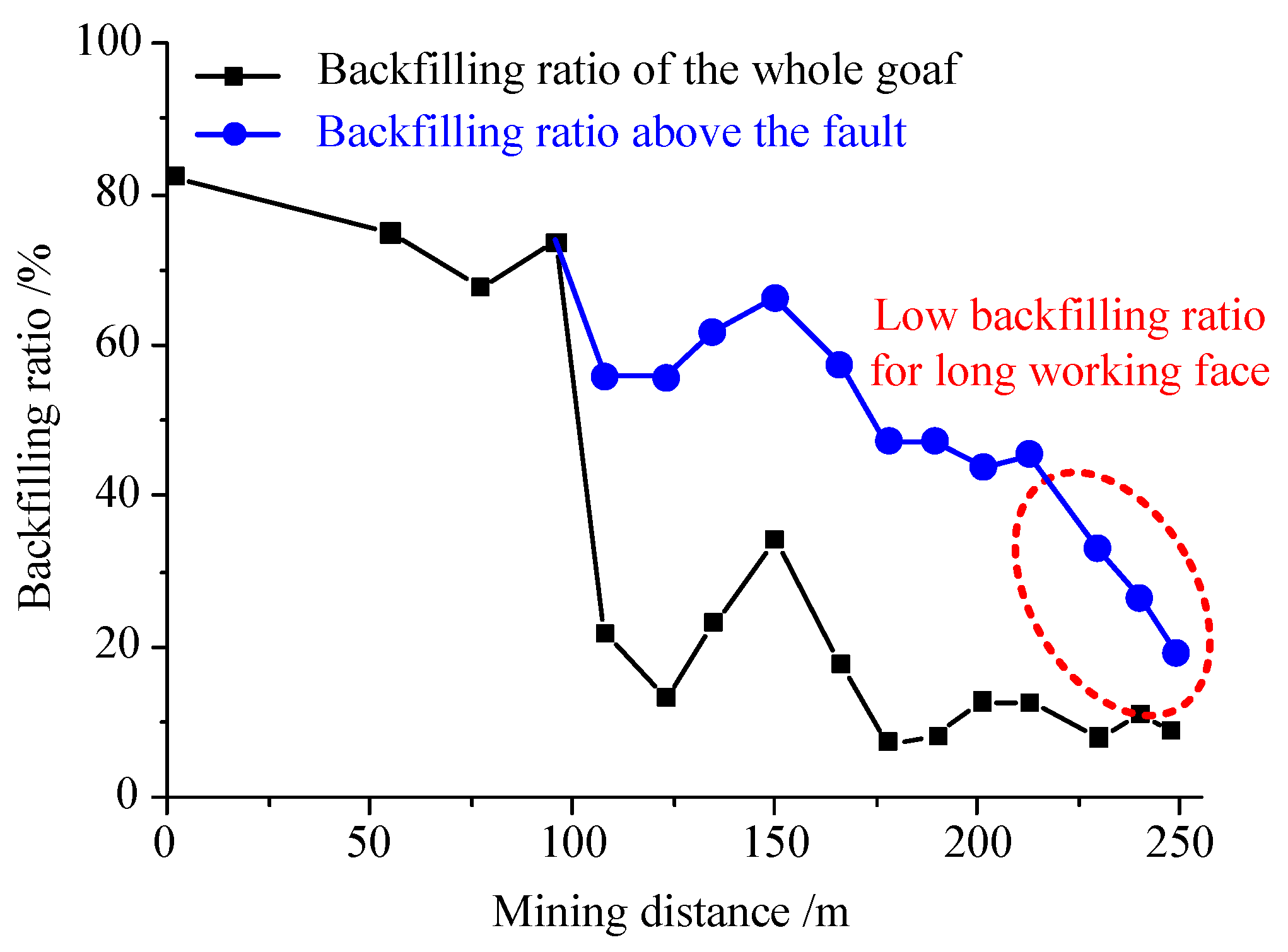
At the early mining stage of the 845 working face (i.e., the face advanced less than 100 m), the backfilling and mining were carried out in a coordinated way, and the gangue backfilling in the goaf was carried out in a timely manner. With continuously mining of the working face, the gangue kept moving to backfill the goaf, and the backfilling ratio (i.e., the ratio of the gangue backfilling volume to coal mining volume at each mining stage) ranged from 67.7% to 82.4%. The backfilling quantity of the gangue was relatively large, as shown in Figure 3.
When the working face passed a fault, subject to the impact of the fault movement, the moving of the gangue in the goaf was constrained, and the backfilling decreased significantly. At this time, if only the upper area above the fault was considered in the goaf, the backfilling ratio still stayed above 50%.
After the No. 1 strip of the working face was exploited, the No. 1 through No. 4 strips were jointly exploited. The inclined length of the working face dramatically increased, and the area of the goaf was enlarged. At this stage, the backfilling significantly decreased, and the backfilling ratio reached the minimum value of 8%. In this stage, the gangue could hardly backfill the goaf.
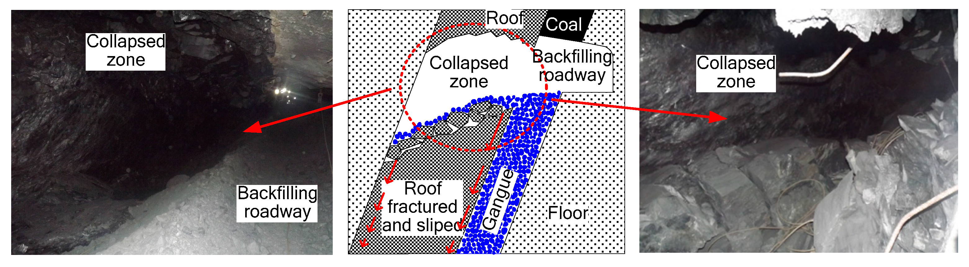
At the early mining stage of the 845 working face, the gangue backfilling ratio was very high, and the corresponding roof deformation was relatively small, with only a slight amount of bending. But when the gangue backfilling quantity decreased to a low value, the controlling effect of the gangue on the deformation of the roof could not fully be brought into play. There was a large-scale roof fracture in the upper gate roadway (i.e., backfilling roadway) of the 845 working face. The fracture depth reached 4 m in the roof, which was almost the thickness of the immediate roof as shown in Figure 4. In contrast to a horizontal or slowly inclined coal seam, the slip of the fractured roof along the incline direction of rock strata resulted in a large collapsed area on the roof at the upper gate roadway [35].
3. Numerical Modelling of Backfilling
3.1. Model Development and Simulation Method
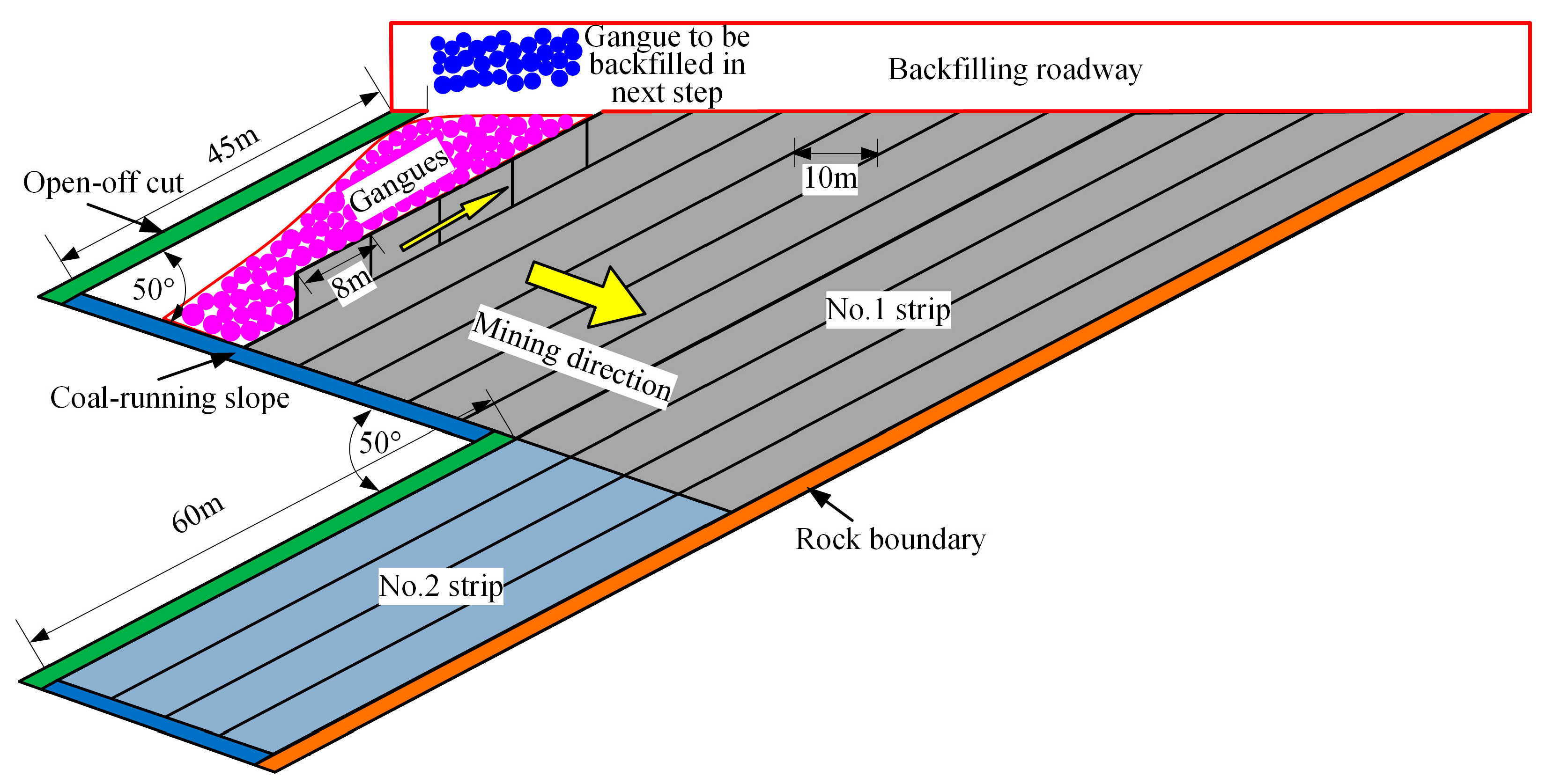
The Particle Flow Code (PFC) has been used widely in geotechnical engineering to simulate geomaterials [36,37]. In this study, PFC2D 3.10 (Itasca Consulting Group, Inc., Minneapolis, MN, USA) was used to study the movement of the gangue in the goaf after mining with flexible shield supports of a steep coal seam and to analyze the influence of the inclined length and arrangement of the working face. Mining of a steep coal seam is a complicated procedure. The simulation is mainly focused on the moving of the backfilled gangue in a simplified way. The boundaries of the strata and coal seam particles were fixed, and only the gangue moved freely under self-weight. The simplified model is shown in Figure 5.
In this simulation, the working face was arranged with an angle of 30°. The contact bond model was chosen to simulation the coal, rock and gangue, and only the frictional coefficient, contact stiffness, density, and particle radius were assigned values without considering the bonding strength [38]. The detailed parameters in the model are shown in Table 2.
To facilitate the calculation, each mining distance for the working face is 10 m in the direction of the coal seam strike, and each mining step is divided into several sections from the bottom to the top of the face, with 8 m section distance. When a step distance of the working face is exploited and after the gangue stops moving, the gangue is backfilled in the goaf. When the gangue cannot be backfilled further, the working face begins to mine the next step. The above process is repeated until the coal layer is completely extracted. After moving forward and mining one step, gangue with a different color is used to backfill and identify the goaf.
To simulate the gangue backfilling process, gangue particles generate randomly in the area above the goaf, and the gangue particles backfill the goaf under the action of self-weight. When the goaf is full, the superfluous particles above the goaf are removed.
3.2. Gangue Backfilling Process
The simulation results show that the backfilling form of the gangue in the goaf constantly changes with the mining of the working face. Considering the change of the backfilling form, the backfilling process of gangue can be divided into four stages: the landslide stage, the small-scale subsidence stage, the funnel-shaped subsidence stage, and the large-scale subsidence stage. These stages are discussed below.
3.2.1. Gangue Landslide Stage
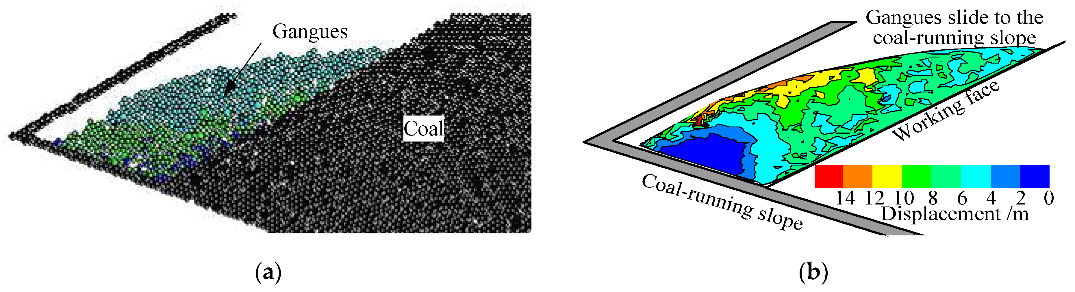
In the early mining stage of the working face, the gangue could not be backfilled in the lower part of the open-off cut because the dip angle of the cut was smaller than gangue’s angle of repose. The quantity of the gangue backfilled in the goaf was lower, and it was mainly concentrated directly above the working face, as shown in Figure 6a. After the mining of the coal seam, the gangue in the surface had larger displacement, and the gangue above the working face slipped toward the coal-running slope, as shown in Figure 6b. This stage was named the landslide stage.
3.2.2. Gangue Small-Scale Subsidence Stage
After the working face advanced 60 m, gangue could almost backfill the goaf fully. There was distinct stratification between the gangue backfilled in different mining stages, and it showed an arc form, which was high on the left and low on the right, as shown in Figure 7a. By analyzing the displacement distribution of gangue, it was found that gangue close to the working face had maximum displacement, and the displacement decreased far away from the working face. There was a sector region of gangue upon the coal-running slope that remained nearly motionless, as shown in Figure 7b.
In this stage, there was a small-sized gangue subsidence pit in the backfilling roadway. The subsidence depth increased from left to right, and the subsidence was most evident near the upper head of the working face. The subsidence movement of the gangue inside the goaf was similar to that of ground surface subsidence, and this stage was named small-scale subsidence stage.
3.2.3. Funnel-Shaped Subsidence Stage
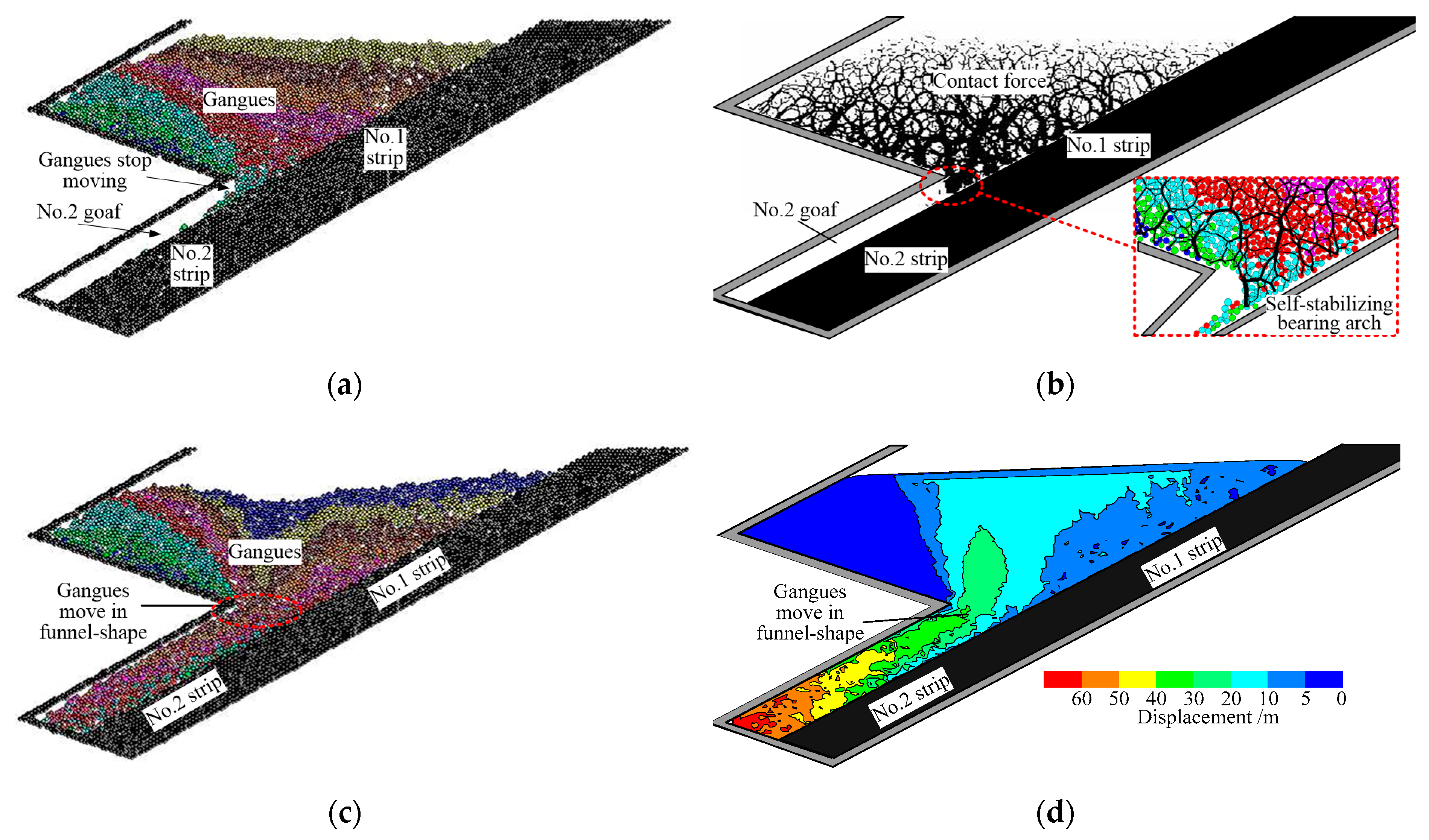
When the No. 1 strip and the No. 2 strip were connected together for mining, the inclined length of the working face increased from 80 m to 140 m. The gangue to backfill the goaf of the No. 2 strip came from the No. 1 strip directly. However, due to the impact of the working face arrangement, only a small part of the gangue entered into the goaf of the No. 2 strip, as shown in Figure 8a. By analyzing the contact force distribution between the gangue, it was found that the contact force increased from the shallow section to the deep section under the application of self-weight, and it reached a maximum value at the connected location of the No. 1 and No. 2 strip, as shown in Figure 8b. Under the restriction of the high extrusion force and the narrow moving space in the connected location, the gangue formed a self-stabilizing bearing arch, which prevented the upper gangue from backfilling the lower goaf.
After the working face advanced 100 m, the width of the connected space of the No. 1 and No. 2 strips extended from 10 m to 20 m. The self-stabilizing bearing arch formed at the prior stage was damaged, and more gangue could backfill in the goaf of the No. 2 strip, as shown in Figure 8c. Different from the small-scale subsidence stage, the displacement of gangue in the middle of the No. 1 strip was larger than the gangue on the two sides, and the gangue upon the coal-running slope still remained motionless, as shown in Figure 8d. The backfilling process and displacement distribution of gangue backfilling in this stage were similar to an inclined funnel, so this stage was named the funnel-shaped subsidence stage.
3.2.4. Large-Scale Subsidence Stage
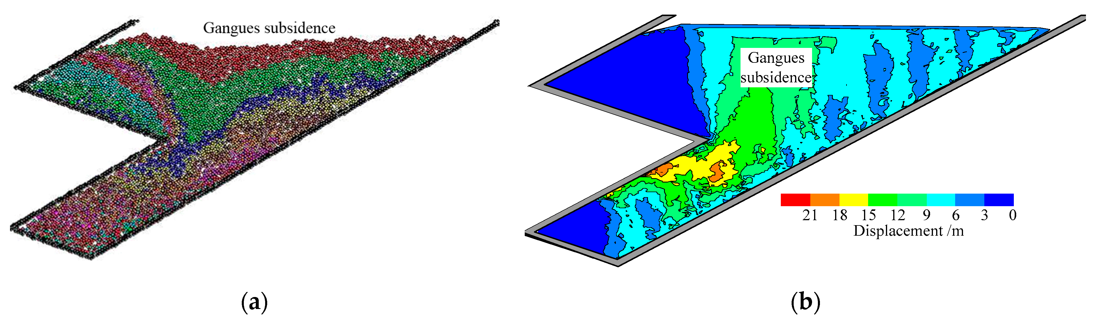
When the goaf of the No. 2 strip was full of gangue, the moving of backfilled gangue showed a V-shape form, and the subsidence pit in the backfilling roadway was larger than that in the previous three stages, as shown in Figure 9a. There were two sector regions where the gangue remained motionless, as shown in Figure 9b. This stage was named the large-scale subsidence stage due to the larger subsidence pit.
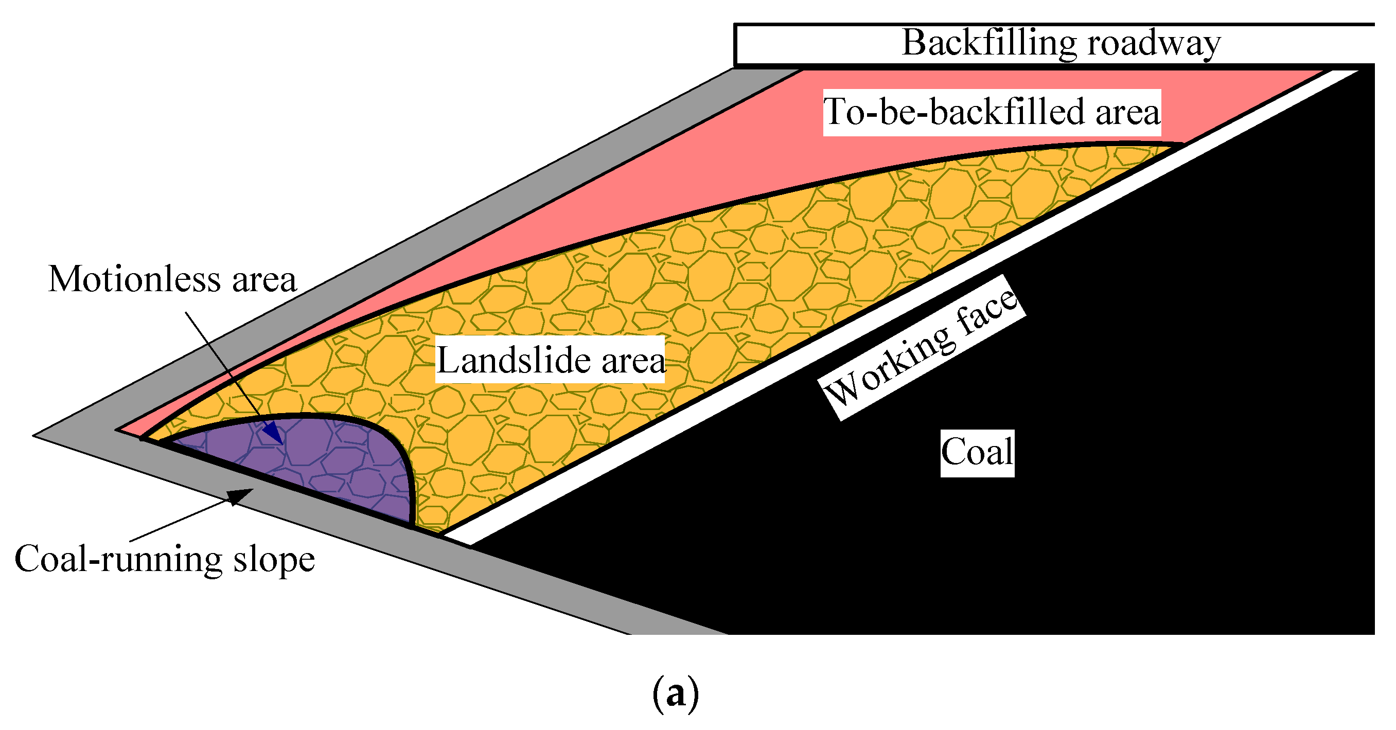
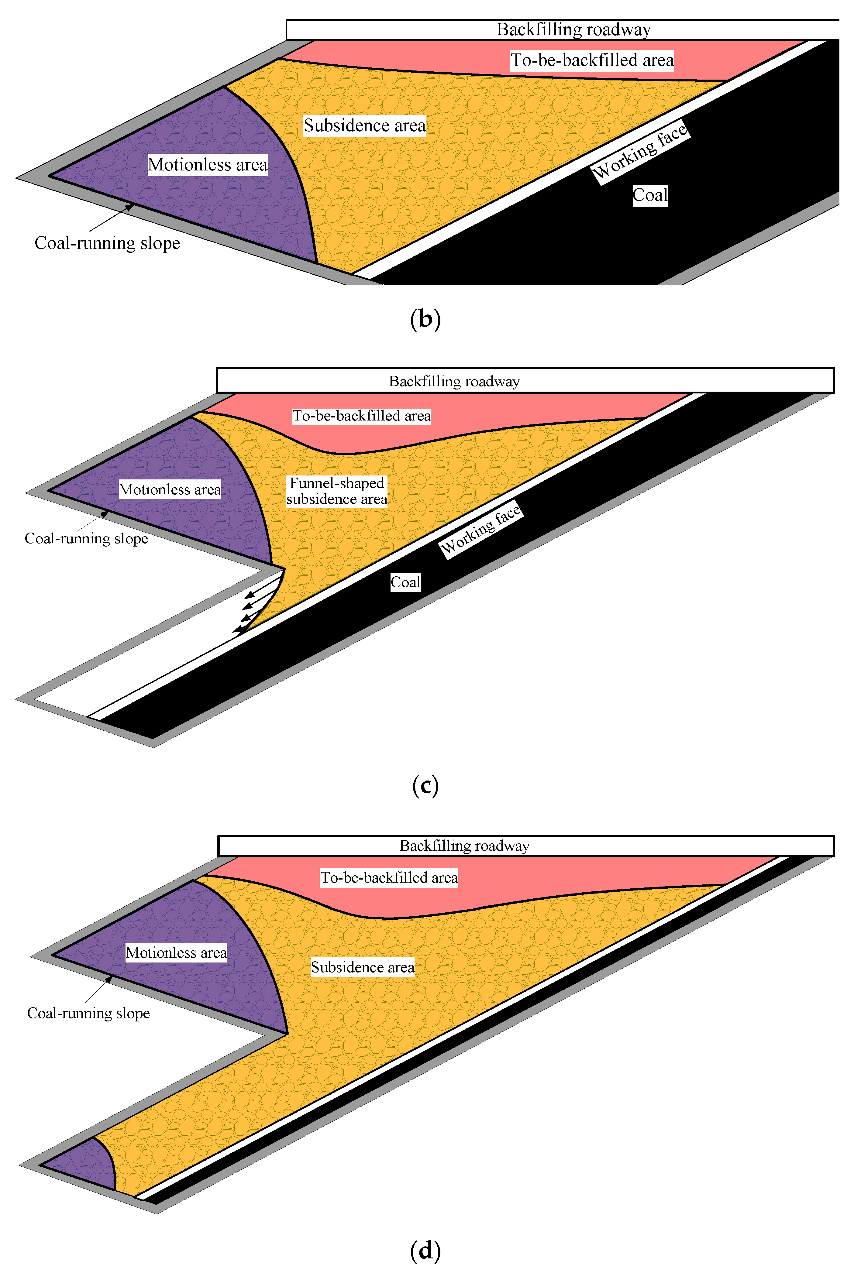
3.3. Gangue Moving Area
According to the displacement distribution and movement direction of the gangue in the goaf during the different backfilling stages, five moving areas can be divided as shown in Figure 10, with the details as follows.
- (1)
- Gangue motionless area: Located in the upside of the coal-running slope, with a moving boundary line that exhibited a sector shape.
- (2)
- Gangue landslide area: Because the gangue above the working face slides towards the coal-running slope, the gangue in the shallow part of the goaf exhibited a larger slide displacement.
- (3)
- Gangue subsidence area: Located between the motionless area of the gangue and the working face. Gangue in this area subsides slowly.
- (4)
- Gangue funnel-shaped subsidence area: Located in the connected space of the two-strip goaf, in which the gangue mainly backfilled the No. 2 strip goaf, and the movement was similar to a funnel.
- (5)
- Gangue to-be-backfilled area: The subsidence pit formed in the shallow part of the goaf at the backfilling roadway was the effective backfilling area of the gangue in the next backfilling operation.
The size of the gangue to-be-backfilled area increased with the increase of the inclined length of the working face, and the distance from the lowest point of the subsidence pit to the upper head of the working face gradually increased. Thus, to backfill the goaf with gangue, it was necessary to transport the gangue to the long-distance part of the goaf, which demonstrated the effectivity of the long-distance backfilling technology with a scraper proposed in the field practice.
3.4. Gangue Moving Time
After the working face advanced forward, the gangue in the goaf slowly moved. The moving of gangue would last some time from beginning to end, and the formation of the subsidence pit at the backfilling roadway lagged behind the mining operation. Therefore, studying the evolution of the gangue moving time with the mining of the working face has a guiding role in optimizing coordination between mining and backfilling operation.
This study examined the time of the gangue moving under two conditions. The first condition was the gangue moving time variation with the inclined length of the working face, i.e., analyzing and comparing the moving time of the gangue in different mining stage. The second condition was the gangue moving time variation with the mining depth, i.e., analyzing the variation of the gangue moving time in the process of the lower head exploited toward the upper head of the working face in one mining stage.
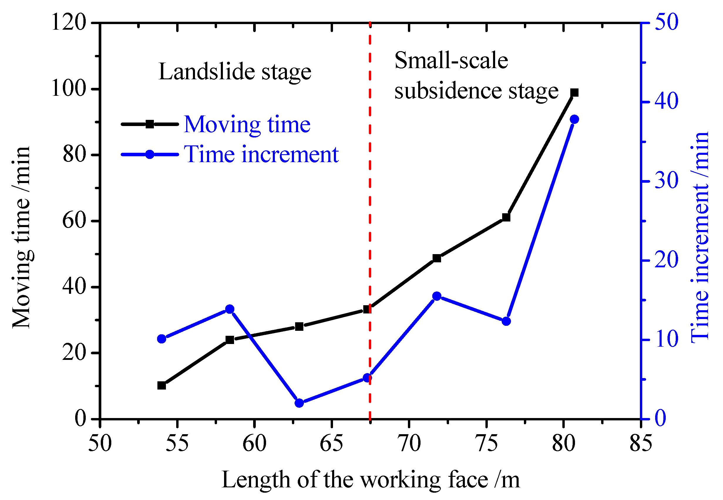
3.4.1. Variation of Gangue Moving Time with the Inclined Length of the Working Face
By calculating the time from mining of the working face to when the gangue stopped moving in each mining stage, the relationship between the gangue moving time and the inclined length of the working face was obtained, as shown in Figure 11. The gangue moving time curve can be divided into two evident stages that are closely related to the gangue backfilling stages. The detailed patterns are:
- (1)
- When the inclined length of the working face was shorter than 67.5 m, the moving time was relatively short, no more than 40 min, and the time increment between mining stages fluctuated. This stage corresponded to the landslide stage, in which the gangue content inside the goaf was lower, and the movement velocity of the gangue after mining was fast.
- (2)
- When the inclined length of the working face was longer than 67.5 m, the time increment between mining stages increased, and the gangue moving time increased rapidly. This stage corresponded to the small-scale subsidence stage, in which the goaf was completely full of gangue, and more time was needed for gangue backfilling.
Overall, with the increase of the inclined length of the working face, the gangue moving time tended to increase gradually, and the time increment between mining stages increased too.
3.4.2. Gangue Moving Time at Various Locations of the Working Face
Taking the stage of the working face mining as 120 m as an example, the vertical height of the working face was about 80 m, and the working face was exploited from the lower head to the upper head. The time of the gangue moving was counted separately every time in order to obtain the variation curve of the gangue moving time, as shown in Figure 12. When mining the coal at the upper head of the working face, the gangue moving time was shorter than 10 min. With the increase of the distance from the coal exploited location to the upper head, the gangue moving time increased. When exploited at the end head, the gangue moving time was longer than 90 min.
4. Discussion
In steep coal seam backfill mining, the gangue material is used to backfill the goaf using its self-weight consolidation. It is very difficult to install monitoring equipment to study the moving law of gangue material in a field test. However, the subsidence pits at the roadway can be observed distinctly. The formation and moving process of subsidence pits during coal seam mining were in accordance with the simulation results of PFC2D, which can verify the correctness of the simulation.
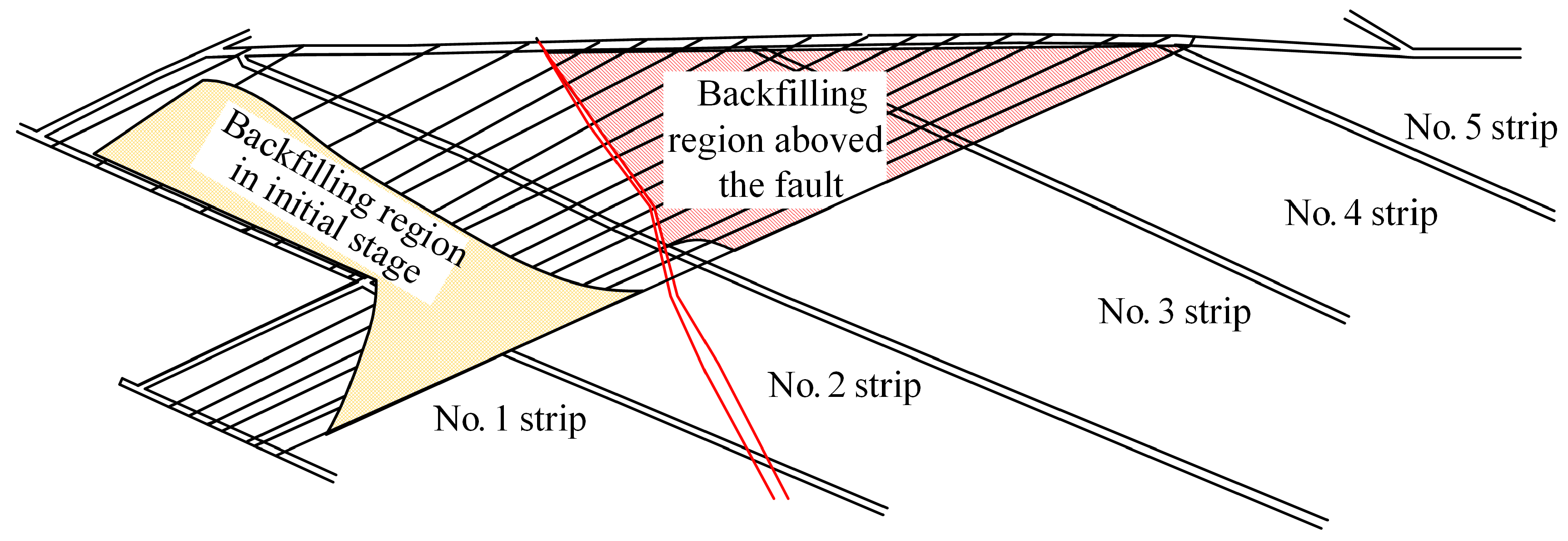
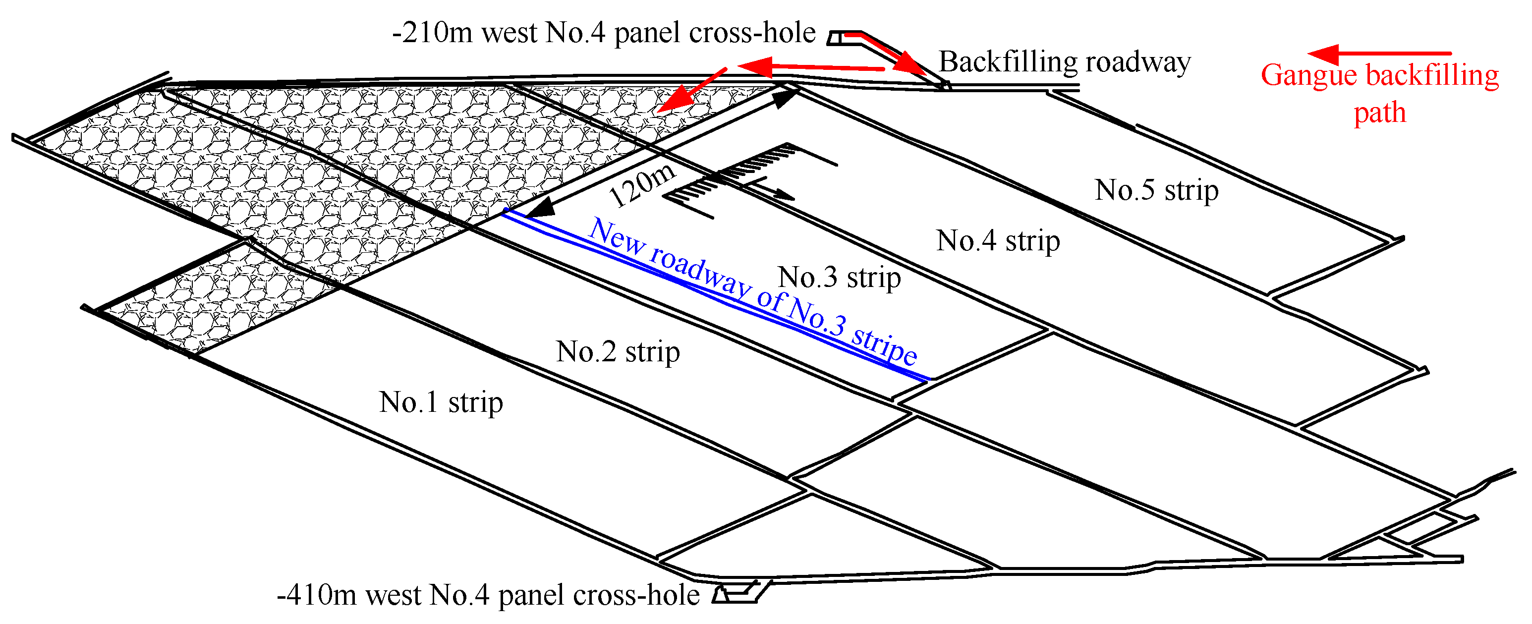
Considering the backfilling process and moving area obtained by the simulation, the backfilling form in the No. 845 working face is inferred and demonstrated in Figure 13. In the initial mining stage, the fault was the main geological factor influencing the backfilling ratio. When the No.1 and No.4 strip were exploited together, the inclined length of the working face dramatically increased, which began to be the main factor influencing the backfilling ratio. Thus, the backfilling ratio can be improved by shortening the inclined length of the working face. A new inclined roadway in the west No. 3 strip was excavated at 120 m from the upper head of the working face, as shown in Figure 14. The working face was divided into two parts. The upper half of the working face was exploited first. The field test indicated that the backfilling ratio in the subsequent mining stage was mostly above 70%, which showed that optimizing the roadway layout and shortening the inclined length of the working face can significantly improve the backfilling ratio.
The simulation and field test of the gangue backfilling show that with the increase of the inclined length of the working face [39], the backfilling ratio decreases. Therefore, in the field application of long-distance gangue backfilling technology with a scraper, some guidelines should be followed.
- (1)
- The inclined length of the working face should be shorter than a specific value to maintain a high backfilling ratio.
- (2)
- When mining geological anomaly areas, especially faults, some measures should be taken in advance to reduce the influence on backfilling operation.
5. Conclusions
This study proposed a long-distance backfilling technology with a scraper winch for steep coal seams and arranged a transport-backfilling entire system of the gangue in Datai Mine. During the practice, it was found that the fault and length of the working face had a strong influence on the backfilling ratio. By means of the numerical simulation of backfilling and mining technology, the moving law of gangue in the goaf was investigated. The gangue inside the goaf mainly experienced four stages: gangue landslide stage, small-scale subsidence stage, funnel-shaped subsidence stage, and large-scale subsidence stage. With an increase in the inclined length and mining depth of the working face, the moving time of the gangue increased gradually.
The moving area of the gangue in the goaf could be divided into five areas including a motionless area, a landslide area, a subsidence area, a funnel-shaped subsidence area, and a to-be-backfilled area. The to-be-backfilled area was the subsidence pit at the backfilling roadway, and it could be backfilled by transporting the gangue to the long-distance part in the goaf, which demonstrated the effectivity of the long-distance backfilling technology with a scraper proposed in this paper. Based on the simulation results, the scheme of backfilling and mining in Datai Mine was optimized, for which the inclined length of the working face was shortened, and a higher backfilling ratio was obtained.
Author Contributions
Methodology, Y.T. and T.Z.; Software, Y.Y. and Y.Q.; Formal Analysis, Y.Z. and Y.T.; Investigation, Y.Y., Y.J. and Y.Q.; writing—original draft preparation, Y.Y. and Y.Z.; writing—review and editing, A.T. and T.Z.
Funding
This research was funded by the National Key R&D Program of China (2018YFC0604703), National Natural Science Foundation of China (51604165, 51874190), Tai’shan Scholar Engineering Construction Fund of Shandong Province of China (ts201511026), and China Scholarship Council (No. 201708370105).
Acknowledgments
The authors would like to thank the editors and the anonymous reviewers for their helpful and constructive comments.
Conflicts of Interest
The authors declare no conflict of interest.
References
- Yao, Q.; Feng, T.; Liao, Z. Damage characteristics and movement of inclined strata with sublevel filling along the strike in the steep seam. J. China Coal Soc. 2017, 42, 3096–3105. (In Chinese) [Google Scholar] [CrossRef]
- Zhang, B.; Cao, S.G. Study on first caving fracture mechanism of overlying roof rock in steep thick coal seam. Int. J. Min. Sci. Technol. 2015, 25, 133–138. [Google Scholar] [CrossRef]
- Guo, W.Y.; Zhao, T.B.; Tan, Y.L.; Yu, F.H.; Hu, S.C.; Yang, F.Q. Progressive mitigation method of rock bursts under complicated geological condition. Int. J. Rock Mech. Min. Sci. 2017, 96, 11–22. [Google Scholar] [CrossRef]
- Huang, W.P.; Yuan, Q.; Tan, Y.L.; Wang, J.; Liu, G.L.; Qu, G.L.; Li, C. An innovative support technology employing a concrete-filled steel tubular structure for a 1000-m-deep roadway in a high in situ stress field. Tunn. Undergr. Space Technol. 2018, 73, 26–36. [Google Scholar] [CrossRef]
- Zhang, G.C.; Liang, S.J.; Tan, Y.L.; Xie, F.X.; Chen, S.J.; Jia, H.G. Numerical modeling for longwall pillar design: A case study from a typical longwall panel in China. J. Geophys. Eng. 2018, 15, 121–134. [Google Scholar] [CrossRef]
- Zhao, T.B.; Guo, W.Y.; Tan, Y.L.; Lu, C.P.; Wang, C.W. Case histories of rock bursts under complicated geological conditions. Bull. Eng. Geol. Environ. 2017, 77, 1529–1545. [Google Scholar] [CrossRef]
- Zhao, T.B.; Guo, W.Y.; Tan, Y.L.; Yin, Y.C.; Cai, L.S.; Pan, J.F. Case studies of rock bursts under complicated geological conditions during multi-seam mining at a depth of 800 m. Rock Mech. Rock Eng. 2018, 51, 1539–1564. [Google Scholar] [CrossRef]
- Wang, Y.; Taheri, A.; Xu, X. Application of Coal Mine Roof Rating (CMRR) in Chinese coal mines. Int. J. Min. Sci. Technol. 2018, 28, 491–497. [Google Scholar] [CrossRef]
- Ning, J.G.; Wang, J.; Bu, T.T.; Hu, S.C.; Liu, X.S. An innovative support structure for gob-side entry retention in steep coal seam mining. Minerals 2017, 7, 75. [Google Scholar] [CrossRef]
- Zhang, J.W.; Wang, J.C.; Wei, W.J.; Chen, Y.; Song, Z.Y. Experimental and numerical investigation on coal drawing from thick steep seam with longwall top coal caving mining. Arab. J. Geosci. 2018, 11, 1–9. [Google Scholar] [CrossRef]
- Yuan, Y.; Tu, S.H.; Wang, F.T.; Zhang, X.G.; Li, B. Hydraulic support instability mechanism and its control in a fully-mechanized steep coal seam working face with large mining height. J. South. Afr. Inst. Min. Metall. 2015, 115, 441–447. [Google Scholar] [CrossRef]
- Tan, Y.L.; Yu, F.H.; Ning, J.G.; Zhao, T.B. Design and construction of entry retaining wall along a gob side under hard roof stratum. Int. J. Rock Mech. Min. Sci. 2015, 77, 115–121. [Google Scholar] [CrossRef]
- Tan, Y.L.; Liu, X.S.; Ning, J.G.; Lu, Y.W. In situ investigations on failure evolution of overlying strata induced by mining multiple coal seams. Geotech. Test. J. 2017, 40, 244–257. [Google Scholar] [CrossRef]
- Zhou, Z.L.; Chen, L.; Cai, X.; Shen, B.T.; Zhou, J.; Du, K. Experimental investigation of the progressive failure of multiple pillar-roof system. Rock Mech. Rock Eng. 2018, 51, 1629–1636. [Google Scholar] [CrossRef]
- Lai, X.P.; Cai, M.F.; Ren, F.H.; Shan, P.F.; Cui, F.; Cao, J.T. Study on dynamic disaster in steeply deep rock mass condition in Urumchi Coalfield. Shock Vib. 2015. [Google Scholar] [CrossRef]
- Liu, X.S.; Tan, Y.L.; Ning, J.G.; Lu, Y.W.; Gu, Q.H. Mechanical properties and damage constitutive model of coal in coal-rock combined body. Int. J. Rock Mech. Min. Sci. 2018, 110, 140–150. [Google Scholar] [CrossRef]
- Tu, H.S.; Tu, S.H.; Zhang, C.; Zhang, L.; Zhang, X.G. Characteristics of the roof behaviors and mine pressure manifestations during the mining of steep coal seam. Arch. Min. Sci. 2017, 62, 871–891. [Google Scholar] [CrossRef]
- Gong, P.; Ma, Z.G.; Ni, X.Y.; Zhang, R.R. Floor heave mechanism of gob-side entry retaining with fully-Mechanized backfilling mining. Energies 2017, 10, 2085. [Google Scholar] [CrossRef]
- Gong, P.; Ma, Z.G.; Zhang, R.R.; Ni, X.Y.; Liu, F.; Huang, Z.M. Surrounding rock deformation mechanism and control technology for gob-Side entry retaining with fully mechanized gangue backfilling mining: A Case Study. Shock Vib. 2017. [Google Scholar] [CrossRef]
- Huang, P.; Spearing, A.J.S.; Feng, J.; Jessu, K.V.; Guo, S. Effects of solid backfilling on overburden strata movement in shallow depth longwall coal mines in West China. J. Geophys. Eng. 2018, 15, 2194–2208. [Google Scholar] [CrossRef]
- Zhang, J.X.; Deng, X.J.; Zhao, X.; Ju, F.; Li, B.Y. Effective control and performance measurement of solid waste backfill in coal mining. Int. J. Min. Reclam. Environ. 2017, 31, 91–104. [Google Scholar] [CrossRef]
- Zhang, J.X.; Li, M.; Taheri, A.; Zhang, W.Q.; Wu, Z.Y.; Song, W.J. Properties and application of backfill materials in coal mines in China. Minerals 2019, 9, 53. [Google Scholar] [CrossRef]
- Zhou, N.; Zhang, J.X.; Yan, H.; Li, M. Deformation behavior of hard roofs in solid backfill coal mining using physical models. Energies 2017, 10, 557. [Google Scholar] [CrossRef]
- Deng, X.J.; Klein, B.; Hallbom, D.J.; de Wit, B.; Zhang, J.X. Influence of particle size on the basic and time-dependent rheological behaviors of cemented paste backfill. J. Mater. Eng. Perform. 2018, 27, 3478–3487. [Google Scholar] [CrossRef]
- Deng, X.J.; Zhang, J.X.; Zhou, N.; de Wit, B.; Wang, C.T. Upward slicing longwall-roadway cemented backfilling technology for mining an extra-thick coal seam located aquifers: A case study. Environ. Earth Sci. 2017, 76, 789. [Google Scholar] [CrossRef]
- Feng, X.J.; Zhang, Q.M. The effect of backfilling materials on the deformation of coal and rock strata containing multiple goaf: A numerical study. Minerals 2018, 8, 224. [Google Scholar] [CrossRef]
- Wu, J.Y.; Feng, M.M.; Xu, J.M.; Qiu, P.T.; Wang, Y.M.; Han, G.S. Particle size distribution of cemented rockfill effects on strata stability in filling mining. Minerals 2018, 8, 407. [Google Scholar] [CrossRef]
- Zhang, X.G.; Lin, J.; Liu, J.X.; Li, F.; Pang, Z.Z. Investigation of hydraulic-mechanical properties of paste backfill containing coal gangue-fly ash and its application in an underground coal mine. Energies 2017, 10, 1309. [Google Scholar] [CrossRef]
- Taheri, A.; Tatsuoka, F. Stress-strain relations of cement-mixed gravelly soil from multiple-step triaxial compression test results. Soils Found. 2012, 52, 748–766. [Google Scholar] [CrossRef]
- Taheri, A.; Tatsuoka, F. Small- and large-strain behaviour of a cement-treated soil during various loading histories and testing conditions. Acta Geotech. 2015, 10, 131–155. [Google Scholar] [CrossRef]
- Zhao, Y.; Soltani, A.; Taheri, A.; Karakus, M.; Deng, A. Application of slag-cement and fly ash for strength development in cemented paste backfills. Minerals 2019, 9, 22. [Google Scholar] [CrossRef]
- Li, J.M.; Huang, Y.L.; Chen, Z.W.; Li, M.; Qiao, M.; Kizil, M. Particle-crushing characteristics and acoustic-emission patterns of crushing gangue backfilling material under cyclic loading. Minerals 2018, 8, 244. [Google Scholar] [CrossRef]
- Li, J.M.; Huang, Y.L.; Qi, W.Y.; Kong, G.Q.; Song, T.Q. Loose gangues backfill body‘s acoustic emissions rules during compaction test: based on solid backfill mining. CMES Comp. Model Eng. 2018, 15, 85–103. [Google Scholar] [CrossRef]
- Li, B.; Ju, F. An experimental investigation into the compaction characteristic of granulated gangue backfilling materials modified with binders. Environ. Earth Sci. 2018, 77, 284. [Google Scholar] [CrossRef]
- Zhao, T.B.; Zhang, Z.Y.; Yin, Y.C.; Tan, Y.L.; Liu, X.Q. Ground control in mining steeply dipping coal seams by backfilling with waste rock. J. South. Afr. Inst. Min. Metall. 2018, 118, 15–26. [Google Scholar] [CrossRef]
- Al-Halbouni, D.; Holohan, E.P.; Taheri, A.; Schöpfer, M.P.J.; Emam, S.; Dahm, T. Geomechanical modelling of sinkhole development using Distinct Elements: Model verification for a single void space and application to the Dead Sea area. Solid Earth 2018, 9, 1341–1373. [Google Scholar] [CrossRef]
- Wang, C.; Deng, A.; Taheri, A. Three-dimensional discrete element modeling of direct shear test for granular rubber-sand. Comput. Geotech. 2018, 97, 204–216. [Google Scholar] [CrossRef]
- Potyondy, D.; Cundall, P. A bonded-particle model for rock. Int. J. Rock Mech. Min. Sci. 2004, 41, 1329–1364. [Google Scholar] [CrossRef]
- Yin, Y.C.; Zou, J.C.; Zhang, Y.B.; Qiu, Y.; Fang, K.; Huang, D.M. Experimental study of the movement of backfilling gangues for goaf in steeply inclined coal seams. Arab. J. Geosci. 2018, 11, 318. [Google Scholar] [CrossRef]
Figure 1.
Roadway layout of the 845 working face.

Figure 2.
Backfilling process and system layout of the 845 working face.

Figure 3.
Variations in the gangue backfilling ratio in the 845 working face.

Figure 4.
Roof fracture at the upper gate roadway.

Figure 5.
Gangue backfilling simulation model of slope flexible shield supporting mining.

Figure 6.
Gangue backfilling characteristics at the landslide stage: (a) backfilling form and (b) displacement distribution.
Figure 6.
Gangue backfilling characteristics at the landslide stage: (a) backfilling form and (b) displacement distribution.

Figure 7.
Gangue backfilling characteristics at the small-scale subsidence stage: (a) backfilling form and (b) displacement distribution.
Figure 7.
Gangue backfilling characteristics at the small-scale subsidence stage: (a) backfilling form and (b) displacement distribution.

Figure 8.
Gangue backfilling characteristics at the funnel-shaped subsidence stage: (a) backfilling form, (b) contact force distribution after the working face advanced 80 m, (c) backfilling form, and (d) displacement distribution after the working face advanced 100 m.
Figure 8.
Gangue backfilling characteristics at the funnel-shaped subsidence stage: (a) backfilling form, (b) contact force distribution after the working face advanced 80 m, (c) backfilling form, and (d) displacement distribution after the working face advanced 100 m.

Figure 9.
Gangue backfilling characteristics at the large-scale subsidence stage: (a) backfilling form and (b) displacement distribution.
Figure 9.
Gangue backfilling characteristics at the large-scale subsidence stage: (a) backfilling form and (b) displacement distribution.

Figure 10.
Division and evolution of the gangue moving area at the (a) landslide stage, (b) small-scale subsidence stage, (c) funnel-shaped subsidence stage and (d) large-scale subsidence stage.
Figure 10.
Division and evolution of the gangue moving area at the (a) landslide stage, (b) small-scale subsidence stage, (c) funnel-shaped subsidence stage and (d) large-scale subsidence stage.


Figure 11.
The relationship between the gangue moving time and the inclined length of working face.

Figure 12.
Gangue moving time variation curve at the double strip mining stage of the working face.

Figure 13.
Inferred backfilling form of gangue in the 845 working face.

Figure 14.
The 845 working face layout after optimization.


Table 1.
Geological characteristics of the overlaying rock strata and the coal seam.
| Stratum | Rocks | Average Thickness (m) | Character Description |
|---|---|---|---|
| Main roof | Siltstone | 14.7 | Gray black, silicon cementation. |
| Immediate roof | Siltstone | 4.1 | Gray black, silicon cementation. |
| Coal seam | No. 5 coal | 1.7 | Black, half bright type. |
| Immediate floor | Siltstone | 7.7 | Gray black, silicon cementation. |
| Main floor | Siltstone | 20 | Gray black, silicon cementation. |
Table 2.
Parameter setup of the gangue backfilling model in the goaf.
| Parameter | Rock Stratum | Coal Seam | Gangue |
|---|---|---|---|
| Density ρ (kg/m3) | 2500 | 1400 | 2500 |
| Radius r (m) | 0.4–0.6 | 0.4–0.6 | 0.4–0.6 |
| Normal contact stiffness kn (GPa) | 5 | 1 | 5 |
| Shear contact stiffness ks (GPa) | 2 | 0.5 | 2 |
| Friction coefficient f | 0.5 | 0.5 | 0.5 |
© 2019 by the authors. Licensee MDPI, Basel, Switzerland. This article is an open access article distributed under the terms and conditions of the Creative Commons Attribution (CC BY) license (http://creativecommons.org/licenses/by/4.0/).
Share and Cite
MDPI and ACS Style
Yin, Y.; Zhao, T.; Zhang, Y.; Tan, Y.; Qiu, Y.; Taheri, A.; Jing, Y. An Innovative Method for Placement of Gangue Backfilling Material in Steep Underground Coal Mines. Minerals 2019, 9, 107. https://doi.org/10.3390/min9020107
AMA Style
Yin Y, Zhao T, Zhang Y, Tan Y, Qiu Y, Taheri A, Jing Y. An Innovative Method for Placement of Gangue Backfilling Material in Steep Underground Coal Mines. Minerals. 2019; 9(2):107. https://doi.org/10.3390/min9020107
Chicago/Turabian StyleYin, Yanchun, Tongbin Zhao, Yubao Zhang, Yunliang Tan, Yue Qiu, Abbas Taheri, and Yuan Jing. 2019. "An Innovative Method for Placement of Gangue Backfilling Material in Steep Underground Coal Mines" Minerals 9, no. 2: 107. https://doi.org/10.3390/min9020107
Note that from the first issue of 2016, this journal uses article numbers instead of page numbers. See further details here.