Multi-Analysis Characterisation of a Vernacular House in Doha (Qatar): Petrography and Petrophysics of its Construction Materials


1
Department of Geology, UTAD—Universidade de Trás-os-Montes e Alto Douro, Quinta de Prados, 5001-801 Vila Real, Portugal
2
Department of Geology, CGeo—Centro de Geociências da Universidade de Coimbra, Rua Silvino Lima, Universidade de Coimbra-Polo II, 3030-790 Coimbra, Portugal
3
Institute of Arab and Islamic Studies (IAIS), University of Exeter, Stocker Road, Exeter EX4 4ND, UK
4
UCL Qatar (University College London), Humanitarium, Education City, P.O. Box 25256, Doha, Qatar
*
Author to whom correspondence should be addressed.
Minerals 2019, 9(4), 241; https://doi.org/10.3390/min9040241
Submission received: 28 March 2019
/
Revised: 16 April 2019
/
Accepted: 16 April 2019
/
Published: 18 April 2019
(This article belongs to the Special Issue Petrography of Construction Materials: Compositional, Mineralogical and Textural Features)
Abstract
:This study characterises the original construction materials (building stones and mortars) of a collapsed two-storey colonnaded structure in the Ismail Mandani house, located in the old city centre of Doha (Qatar). Results were drawn based on interpretation and integration of historical, in situ observations and analytical data. The mortars and stones were characterised following a multidisciplinary approach, combining macroscopic observation with petrographic microscopy, mineralogical analysis (X-ray diffraction) and elemental analysis (handheld X-ray fluorescence) of samples. Moreover, hydric properties, ultrasonic pulse velocity and colour of representative samples of the house were studied. The results revealed the use of two types of stones and three different types of gypsum mortars. The original construction materials came from nearby coastal stones. Gypsum of the most used mortar had a calcination temperature between 120 and 160 °C and its colour was produced by lumps with higher Fe content. The materials’ effective porosity and water absorption were high, and their ultrasonic pulse velocity was low. These petrophysical results indicated they had low quality for construction purposes. The composition and colour of the original construction materials were quantified, which will allow the reproduction of their aesthetic characteristics and improvement of their quality in future reconstruction works.
1. Introduction
Historical construction materials have an important aesthetic, cultural and heritage value, and their characteristics must be conserved so that historic centres maintain their identity. The transformation of urban centres results in many historic houses losing their original use [1]. For conservation to go hand in hand with development, appropriate strategies must be defined in an interdisciplinary way [2]. It is necessary to collect data on construction materials of buildings before they disappear [3,4]. The characterisation of construction materials is essential for archaeology, architecture and town planning. In particular, the study of their petrographic and petrophysical properties is fundamental for maintenance, restoration and reconstruction of heritage buildings to be effective [5,6,7]. The science of materials allows identifying the causes of built-heritage decay. It can provide the means needed to mitigate the factors that contribute to the loss of built heritage [8,9,10]. In addition, it allows the optimisation of materials to adapt them to their current use and environmental conditions. Petrological and petrophysical properties like effective porosity, bulk density, water absorption capacity and ultrasonic pulse velocity, determine construction materials’ quality, durability and decay [11,12,13,14]. Environmental conditions like temperature, humidity and salt presence also condition the decay of buildings [15,16,17].
Normally, regional geology determines the building stones of a given place. Traditionally, construction raw materials for vernacular architecture came from the vicinity of the building in which they would be used [18,19]. Geologically, Doha is located on the eastern basin of the Qatar anticline stretching from sea level to the east. Due to sea level changes throughout the quaternary in the Persian Gulf [20,21] there are a variety of coastal deposits. Quaternary units of Doha are found on or close to the surface and are mainly made of marine sediments, residual soil and cemented beach rocks. The underlying bedrock units are largely horizontal to sub-horizontal marine carbonates and evaporites comprising limestones, shales, siltstones, mudstones, marls and gypsum.
Simsima limestone member of the Upper Dammam Formation (middle Eocene) outcrops over 80% of the land surface of Doha area [22]. This formation is underlain by the Lower Dammam Formation, which is in turn underlain by the Rus Formation. This stratigraphic succession is consistent throughout Doha with spatial variances. In particular, the Lower Dammam Formation can be locally eroded. The Upper Dammam Formation was frequently used in construction, and it was the main foundation for most buildings in Doha. Due to its use, there are several studies about its petrophysical and geotechnical properties [22,23]. However, quaternary stones were also used in ancient constructions of Doha. Thus, petrological and petrophysical studies of these stones, aimed at restoration and conservation purposes, are necessary.
As stated above, the historical buildings of Doha were usually constructed with quaternary stones of coastal origins. Their mortars were made with gypsum and aggregates of different origins, according to the use for which they were designed. Gypsum mortar was used as a binder in walls of buildings since before the Egyptian civilisation, and in the Middle East this construction material was widely used [24,25,26]. However, this material is difficult to replicate, since its raw materials used to be local and each mason used his own ratio of binder to aggregates. Gypsum mortar is obtained at lower temperatures than lime mortar, which has better mechanical and petrophysical characteristics [27,28,29]. In addition, gypsum is more water-soluble than calcite, so gypsum mortars are more suitable for indoor use. The use of gypsum mortar in historical buildings of Doha was due to the scarcity of wood to reach the high temperatures necessary for limestone calcination [30,31].
This study aimed primarily at the petrographic characterisation of the construction materials (stones and mortars) of the house of Ismael Mandani located in the urban centre of Doha. That is to say, to determine the composition, texture and porosity, as well as the hydric properties and colour of its original building stones and mortars.
According to [32], the Ismail Mandani house may date back to as early as 1925. Inspection of aerial imagery from 1934 and 1937, 1947, 1952 and 1953 indicate that the area was certainly built up by the mid 1930s, but images from 1947, 1952 and 1953 show that it did not reached its final form until the latter date. More specifically, the collapsed two-storey colonnaded structure, from which the samples were taken and upon which this paper focuses, was constructed some time between 23 May 1952 and 17 October 1953 [33]. At this time, Doha had recently entered a phase of explosive growth, following the commencement of direct oil revenues early in 1950, and this was reflected not only in outward expansion of the town, but also extensive renovation, rebuilding and additions to the buildings of the older districts, as seen in the Ismail Mandani house. The increased income available to Qataris appears to have translated into increased use of more expensive building materials, namely gypsum or lime plaster instead of clay-rich mud, which had previously been used only in a minority of elite buildings, as well as the construction of large numbers of unified courtyard houses with two-storey elements, also previously restricted. As the 1950s progressed, traditional building materials (local stone; mud, gypsum and lime mortars and plasters; imported mangrove poles to support the roofing) were increasingly supplemented and eventually replaced by modern materials (cement blocks; cement-based mortars and plasters; machine-cut hardwood roof timbers). These modern materials were initially used to replicate old forms of vernacular architecture such as courtyard houses [34], but they do not appear to be present in sampled elements of the collapsed two-storey wing of the Mandani house, suggesting that the use of cement blocks and cement-based mortars and plasters had not yet become common when it was built.
The architectural characteristics and features of the Mandani House reflect its high status and the wealth of its owners. These characteristics include the presence of a second storey, as well as incorporation of recesses and gypsum decorations both internally and externally. Historically, the vernacular houses of Doha, frequently incorporate such later additional building volumes. The courtyard houses that are occupied by the members of extended families often grew incrementally by the addition of new rooms according to changing needs of expanding families [31]. The majority of the house is constructed of construction materials typical of the pre-oil period: mud and limestone walls and flat roofs built of mangrove beams (danshal), overlaid with a layer of split bamboo, woven reed, a palm mat (manghrour) and tamped down earth [30,31].
During the 1970s and 1980s, Qatari government’s redevelopment strategies for the older neighbourhoods of Doha, as well as practice of providing land and housing grants to its citizens, resulted in a major relocation of the Qatari families from the city centre to the growing suburban sprawl. As a result, their older courtyard houses were rented to the low-income migrant workers, often as shared accommodations [34,35,36]. Although the exact departure date of its original inhabitants and the arrival date of its migrant residents are unknown, eventually the Ismail Mandani house was no exception to this practice. Prior to the collapse of the two-storey colonnaded structure, male Pakistani residents inhabited the house. One of them lived in the house for the past 8 years while his son recently joined him at the time of our visit. Commonly, the migrant population inside these houses is very dynamic, and it is hard to know the exact residents throughout their history. Nevertheless, following the practice of the Qatari families, the migrant population inhabiting these houses had also made adaptations and additions to them. The motivations for these adaptations include responses to their various domestic needs as well as maintenance of the buildings. These adaptations are often made with cheap and less permanent materials that are at disposal of their low-income residents. In the case of Ismail Mandani house, cement blocks, pieces of square machine cut timbers, plywood and corrugated steel sheet were used for additional structures. Furthermore, additional layers of cement and metal scaffolding were used for the support of weathered parts of the building including the arched colonnade that later collapsed with the heavy rain after its estimated 65 years lifetime.
2. Materials and Methods
The petrographic characterisation carried out combined naked-eye and binocular magnifier observations with the study of thin sections under polarised light microscopy. The mineralogical characterisation was carried out with X-ray diffraction. Elemental analysis was carried out with handheld X-ray fluorescence and the petrophysical characterisation with measurements of ultrasonic pulse velocity, colour and hydric properties. These analyses were carried out on two stones and three mortars selected from the collapsed two-storey colonnaded structure of the Ismael Mandani house, that is, areas that preserved the original materials from the 1952/3 modification. Materials that do not belong to the original construction were left out.
2.1. Construction Materials
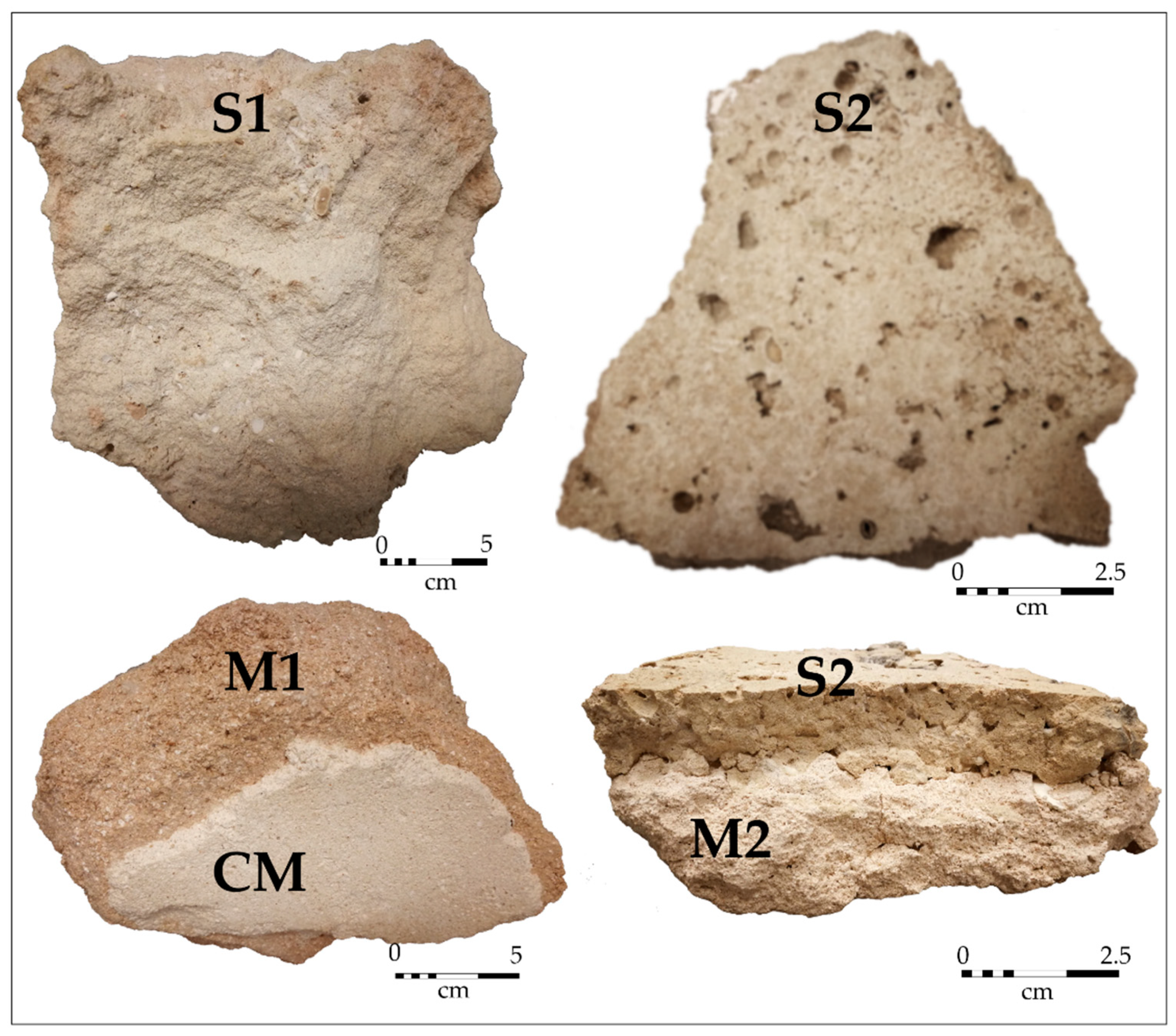
A visual inspection was made of the vernacular construction materials of the house. Two types of stone were identified: S1, the stone most used in the house, a whitish stone forming part of the masonry of the walls and columns; and S2, a brown flat stone located on the upper perimeter of the first floor and in the thin non-load-bearing walls, covering architectural openings. Three types of traditional mortars were sampled: M1, the masonry mortar most used in the house. It cemented the whitish stones (S1), inside the walls and columns, light brown; M2, the mortar that cemented the flat stones (S2), light grey; and CM, the coating mortar (plaster), surface finishing of the walls and columns, white.
The wall, columns and masonry stones dimensions could be measured directly due to the collapse of part of the house (Figure 1). The thickness of the wall and diameter of the columns was obtained by calculating the average of ten measurements. The dimensions of the original building stones were obtained by calculating the average of ten measurements in each of the three perpendicular directions: the largest, the smallest and the perpendicular to both.
Six cubic specimens of 5 × 5 × 5 ± 0.5 cm were cut from S1, S2, M1 and M2 for petrophysical tests. The CM had a thickness of less than 1 cm. It was mechanically detached from the M1 to which it was attached, and its thickness was measured. The final value was the average of ten values. Six rectangular cuboids of 25 × 25 × 5 ± 0.5 mm were obtained for petrophysical tests. All specimens were cut at a low speed (120 rpm) and low strain.
2.2. Petrographic Microscopy (PM)
Three thin sections of each construction material (S1, S2, M1, M2 and CM) were made and observed under a polarisation microscope Leica DM4500 P (Leica microsystems GmbH, Wetzlar, Germany) with intelligent light and contrast management equipped with a digital FireWire Camera Leica DFC290 HD (Leica, Solms, Germany) that worked with the Leica application suite software LAS 4.9 (Leica microsystems GmbH, Wetzlar, Germany).
2.3. X-Ray Diffraction (RXD)
A fragment of each construction material (S1, S2, M1, M2 and CM) was pulverised in an agate mortar to an approximate size of 50 μm to conduct powder X-ray diffraction tests (XRD). This technique has determined the principal mineralogical composition. For the XRD analysis a MiniFlex benchtop X-ray diffractometer (Rigaku, Tokio, Japan) operated at 40 KV and 30 mA was used with a copper anode tube and a graphite monochromator.
The powdered samples were analysed with Cuα radiation. The measurements were performed in a range between 2 and 68 degrees with an interval of 0.02 and 2/min in continuous mode, and they were processed with Miniflex Guiadance and PDXL 2 Rigaku Diffraction software (Version 2, Rigaku Corporation, The Woodlands, TX, USA).
2.4. Effective Porosity (Pe)
S1, S2, M1, M2 and CM samples were tested for the effective porosity (Pe) parameter using the natural stone method described in European standard EN 1936 [37]. After oven-drying at 70 °C to a constant weight (variation in two consecutive weighings over 24 h < 0.1%), they were stored in a desiccator for 30 min. Afterwards they were set in a vacuum chamber at 2 kPa for 2 h. Finally, they were slowly submerged in water and subsequently stored at atmospheric pressure for 24 h to ensure full saturation. The Pe values were calculated following Equation (1):
where Wd is the weight of the dry specimens (after oven-drying at 70 °C and desiccation for 30 min). Ws is the weight of the 24 h water-saturated sample, and Wh is the weight of the sample submerged in water.
Pe (%) = [(Ws − Wd)/(Ws − Wh)] × 100 (%)
2.5. Water Absorption
The water absorption capacity of construction material was defined as the quotient between the weight of water that it has absorbed and its own dry weight. It was expressed in a percentage according to Equation (2):
Water absorption capacity = (Ws − Wd)/Wd × 100 (%)
S1, S2, M1, M2 and CM samples were tested for water absorption.
2.6. Bulk Density (ρb)
Bulk density (ρb) was calculated according to European standard UNE-EN 1936 [37] as the ratio between specimen mass and its bulk volume, following Equation (3):
ρb = [(Wd)/(Ws − Wh)] × 1000 (kg/m3)
S1, S2, M1, M2 and CM samples were tested for ρb.
2.7. Ultrasonic Pulse Velocity (Vp)
Ultrasonic pulse velocity (Vp) measurements were taken with CNS Electronics PUNDIT (Lodon, UK) equipment (precision: ±0.1 μs) according to European standard EN 14579 [38] recommendations. Transducers of 1 MHz frequency with a round shape (11.82 mm in diameter) and a flat surface were affixed to the samples surface with Henkel Sichozell Kleister (a carboxymethyl cellulose) paste and water to enhance the transducer-stone contact and bond.
Vp was measured on each sample (S1, S2, M1, M2 and CM) in the three orthogonal directions, taking the mean of four consecutive measurements on each side of the cubes and cuboid as the represantive value.
2.8. Colour
A camera with Leica lens and a sensor of 12 MP and a D65 illuminant was used for the calculation of the chromatic parameters. After oven-drying at 70 °C to a constant weight, 10 colour measurements were taken in each sample (S1, S2, M1, M2 and CM), and the average for each sample were calculated. Afterwards each sample were moistened with a water sprayer and 10 measurements of the colour were taken again in the wet samples. The CIELAB system (CIELAB, 1976) colour parameters were calculated with Color Grab 3.6.1 software: luminosity (L*), chromatic coordinate from red to green (a*) and chromatic coordinate from blue to yellow (b*). Once the average of the chromatic parameters of each dry and wet construction material was determined, the colour difference between the in dry and wet state was calculated following Equation (4):
ΔE* = [(ΔL*)2 + (Δa*)2 + (Δb*)2]1/2
2.9. Handheld X-Ray Fluorescence
Elements of the samples were identified and analysed speedily, semi-quantitatively and non-destructively with a handheld X-ray fluorescence analyser Olympus DELTA positioned in a lab stand. The measurement of each sample was taken with a voltage of 40 kV and a current of 79 μA in the rhodium (Rh)-based X-ray tube. The measurements were taken directly on the freshly cut sample and relatively flat surfaces with a measuring time of 60 s. The samples were clean of visible dirt to eliminate possible contaminants affecting the measurement. The readings reported in this study are the mean of three measurements taken at different locations on each sample to compensate for the heterogeneity of the construction materials.
A silicon drift detector (SDD) detected the emerging X-ray fluorescence (XRF). The spectral data was processed by the XRF-spectrum evaluation software AXIL (Analysis of X-ray spectra by Iterative Least Squares) for the deconvolution of complex spectra. As no dedicated standards are available for the analysis of building stones and mortars, it has not been possible to calculate reliable concentrations.
3. Results
3.1. In-situ Measurements and Observations
The average thickness of the collapsed wall was 50.1 ± 0.3 cm. The columns have had an average diameter of 39.5 ± 1.3 cm. Both elements were composed of masonry stone S1, with average dimensions of 19.5 ± 8.5 × 14.1 ± 6.1 × 9.5 ± 4.2 cm, and of masonry mortar M1. The average thickness of the coating mortar (CM) was 7 ± 3 mm. (Figure 2).
S1 is a sedimentary stone; it has a whitish colour, sand-size grains and fragments of foraminifera, gastropods and bivalves’ fossils. The fossils are millimetric in size but occasionally measure a few centimetres. There are moldic pores visible to the naked eye (Figure 2 and Figure 3).
S2 is a sedimentary stone, it has a brown colour, sand-size grains and fragments of gastropods and bivalves. The size of the fossils is slightly larger than in S1 samples. There are burrows that in many cases have lost their filling. Bivalves were observed on the exposed surface of these burrows. S2 has average dimensions of 34 ± 16.3 × 28.3 ± 14 × 6.6 ± 1.5 cm (Figure 2 and Figure 3).
M1 is the masonry mortar of S1, with a homogeneous light brown colour. Its aggregates are observable to the naked eye. They are homogeneous and without preferential orientation. They are light grey, light brown and white (Figure 2 and Figure 4).
3.2. Petrographic Microscopy (PM)
S1 has well-sorted and rounded fine-grained ooids (average grain size of 190 ± 54 µm) with a good concentric structure. The oolites are in contact and have a micritic matrix. Spaces between oolites are not fully cemented and rarely meniscus cement is at ooid contacts. When this happens, there are calcite crystals around the pores (drusy crystals). There are bioclasts, especially fragments of bivalves and gastropods, that can reach a few millimetres in size. The oolites have abundant intergranular pores (approximately 20%) and moldic pores due to the dissolution of fossils. Moldic pores also presents perimetral drusy crystals. In some cases, fossil chambers are not filled with cement and also present perimetral drusy crystals. There are angular quartz grains (<10%) that are homogeneously dispersed with an average size of 103 ± 2 μm. This stone is classified according to [39,40] as oomicrite and according to [41] as packstone (Figure 5).
S2 has low-sorted and rounded medium-grained ooids (average grain size of 405 ± 165 µm) with a very good concentric structure and a micrite matrix. Spaces between oolites are not fully cemented and sometimes meniscus cement is at ooid contacts. That is, oolites have abundant intergranular porosity (approximately 15%) and there are bioclasts and gastropods with an average size of 520 μm on their longitudinal axis. Gastropod chambers are not always cemented and present perimetral drusy crystals. S2 has a lower amount of quartz than S1. Quartz grains in S2 have an average size of 194 μm. Burrows’ walls are not cemented, and inter-oolytic porosity is lower than in S1. S2 is classified according to [39,40] as oomicrite and according to [41] as packstone (Figure 5).
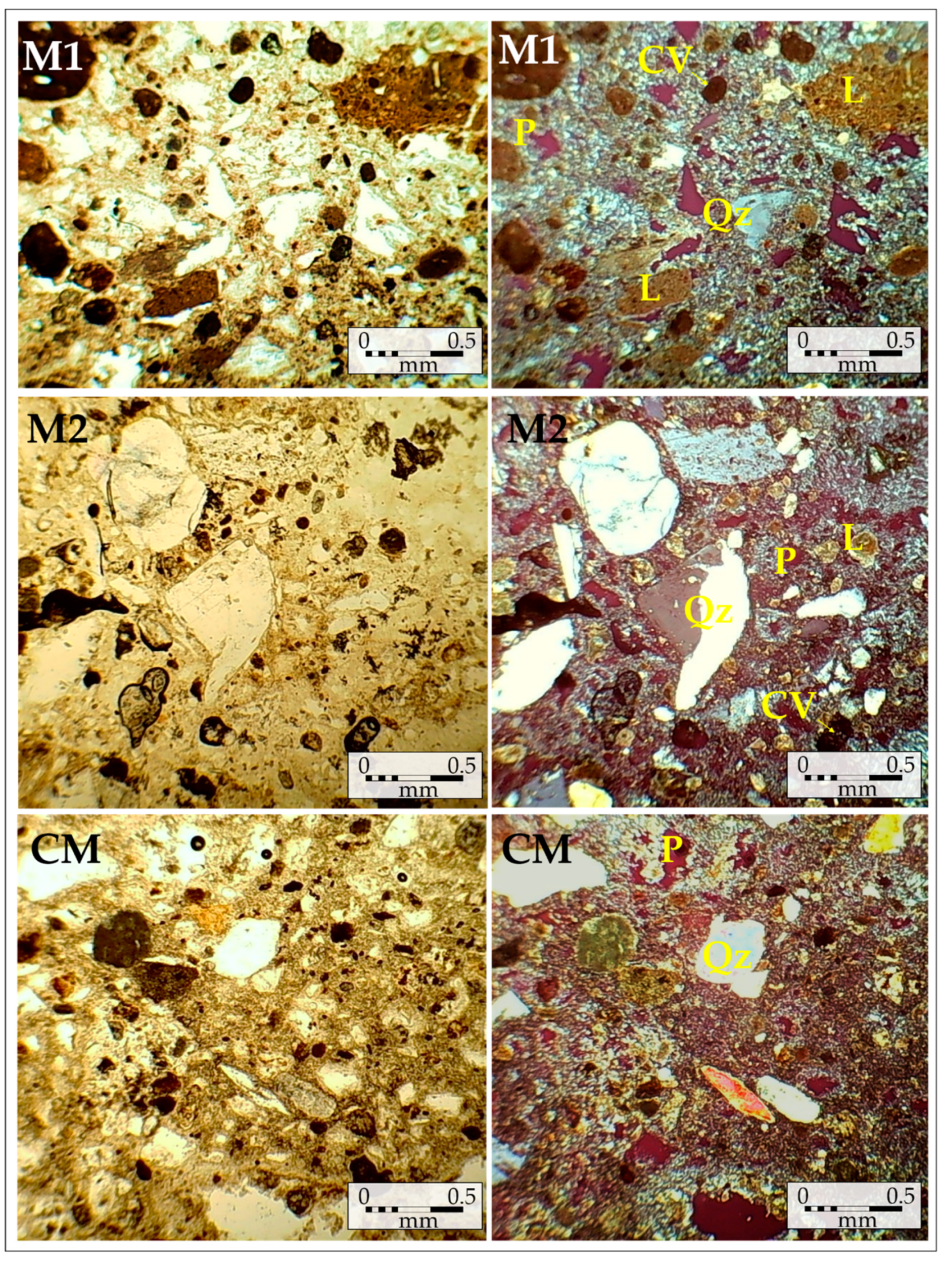
M1 has a gypsum binder. The aggregates are composed mostly of dark lumps, browns and sub-rounded. Sub-rounded and angulated quartz grains are in very low proportion (<5%) with an average size of 230 µm, scarcely vegetal fragments of palm trees were observed (Figure 6 and Figure 7). M1 binder/aggregate ratio is approximately 4:1. The porosity corresponds to sub-rounded pores with no filling (Figure 6).
M2 has a gypsum binder. Aggregates are composed of angular quartz fragments (35%) with heterogeneous shape, dark browns and sub-rounded lumps were observed in smaller proportion than in M1. Few fragments of bivalves and oncolites were observed. M2 binder/aggregate ratio is approximately 3:1. The porosity corresponds to sub-rounded pores with no filling (Figure 2 and Figure 4).
CM has a gypsum binder. Aggregates are composed of sub-angular quartz fragments with an average size of 329 µm with heterogeneous shape (<10%) and dark sub-rounded lumps are representative. CM binder/aggregate ratio is approximately 4:1. The porosity corresponds to sub-rounded pores with no filling (Figure 2 and Figure 4).
The contact between CM and M1 is straight and without porosity (Figure 7). It has good adherence.
3.3. X-Ray Diffraction (XRD)
The mineralogical analysis with XRD has indicated that the mineral compositions of the two stones are very similar. The stones are composed mainly of calcite (Cal), quartz (Qz) and dolomite (Dol). S2 has also aragonite (Arg) (Figure 8). The abbreviations of minerals were written according to [42].
The mineralogical composition of the three mortars was similar. All mortars have shown gypsum, quartz, bassanite and calcite in different proportions: M1 has more gypsum, M2 more bassanite and CM more quartz. But mineralogical differences were observed, M1 has shown vaterite and M2 and CM have shown anhydrite (Figure 9).
3.4. Effective Porosity (Pe), Water Absorption and Bulk Density (ρb)
The analysed masonry stones (S1 and S2) and mortars (M1, M2, and CM) have shown high effective porosity, which ranged between 20.4% for S2 and 30% for S1. Water absorption ranged between 10.4% for S2 and 21.2% for M1. Bulk density ranged between 1280 kg/m3 for CM and 1978 kg/m3 for S2. Table 1 shows the values obtained for Pe, water absorption and ρb of the two stones and the three mortars analysed.
3.5. Ultrasonic Pulse Velocity (Vp)
Vp analysis is a portable technique that depends on the density, porosity, mineralogy and elastic properties of the tested material. Vp provides an accurate measure of the state of construction materials [43,44]. The analysed samples have shown low Vp values, indicating their low quality for construction purposes. The stones have had higher Vp than the mortars. CM has shown the lowest Vp and S2 has shown the highest Vp. Table 2 shows the Vp values for the analysed materials.
3.6. Colour
Table 3 shows the chromatic parameters of the analysed stone and mortar samples. All samples have shown light colours, and when wetted they became darker. The sample that experienced the greatest change in colour was M1.
3.7. Handheld X-Rayfluorescence
The major elements detected by the X-ray fluorescence analyser were Ca, Si, S and Fe (Table 4). The stones have shown higher content of Ca, and the mortars have shown higher content of S. CM was the construction material with the highest content of Si and the lowest content of Ca. Fe was found in the lowest percentage in S2, and M1 was the material that had the highest percentage of Fe.
4. Discussion
The measurements and observations carried out in situ have shown that Ismail Mandani house was poorly maintained and had partially collapsed.
S1 and S2 were petrographically classified as oomicrites and packstones according to [38,39,40,41]. Both stones have shown low compaction with high interoolitic porosity, but there were differences between them. S1 has shown smaller grain size and higher quartz content than S2. The micrite was formed in protected low-energy coastal environments and the quartz grains came from the erosion of rocks external to the sedimentation environment. The presence of burrowing bivalves in the surface of S2 has indicated that this stone comes from the tidal zone of the coast [45]. Probably the stones came from nearby areas to the house, although it has not been possible to locate the historical quarries due to the great urban growth experienced by Doha in the last decades [46].
The textural and compositional similarity of the mortars have indicated a similar elaboration process, although aggregates of the three mortars were petrographically different both in size and shape. M1 has shown the greatest number of lumps and it has had more carbonated aggregates than siliceous ones. M1 quartz grains were scarce, small and sub-rounded, which have indicated that quartz came from the crushing of carbonated stones. M2 had the highest percentage and grain size of quartz fragments. These fragments were generally angular, which has indicated that it came from the crushing of more siliceous rocks than those used in M1. The presence of oncoliths as aggregates in M2 has suggested the use of carbonate stones; they could be of the same type or similar to the masonry stones.
CM has shown more aggregates of quartz than of carbonate, and the size of the aggregates was the most homogeneous of the three mortars, which has indicated a more exhaustive selection of the raw materials. CM was well adhered to M1.
The setting and hardening of a gypsum mortar occur by adding water and aggregates to calcined gypsum. An endothermic reaction produces the crystalline structure [47,48]. M2 and CM diffractograms have shown anhydrite (CaSO4), which means that the gypsum (CaSO4·2H2O) was probably calcined at a temperature higher than 200 °C, necessary to eliminate the two water molecules. Anhydrite has not been detected in the XRD of M1. But bassanite (CaSO4·0.5H2O) was detected in the M1 diffractogram. This means that probably the gypsum of M1 was calcined at temperatures of between 120 °C and 160 °C for its binder elaboration.
M1 has shown vaterite; it is a low-temperature anhydrous polymorph of calcium carbonate and metastable phase that transforms to calcite from approximately 440 °C [49,50]. This spherulitic variety of CaCO3 came from the crystallization of calcium carbonate solutions. Its presence could be explained due to a high concentration of SO42− in the mortar paste. This sulphate could have come from the dissolution of the gypsum. When SO42−: CO32− ≥1, vaterite persists as a major CaCO3 phase-component of the precipitate. That is, the high concentration of sulphate in a solution has contributed to destabilise the calcite and stabilise the vaterite in M1 [51]. In addition, the presence of vaterite could be related to microbial activity. In fact, besides being formed at low temperature by hydration of calcium silicates in the presence of CO2, the genesis of vaterite can be organic [52,53].
In situ assessment of the Ismail Mandani house and its construction materials properties, in addition to meteorological data indicate that determining factors of its collapse were natural, both intrinsic (petrographic and petrophysical properties) and extrinsic (weather); and anthropogenic (usage and poor maintenance).
Regarding petrophysical properties, stones and mortars showed high Pe (higher than 20%). Their ρbs were low, especially in mortars (Table 1). These data have indicated the susceptibility of the construction materials to decay due to their high-water absorption. After studying the hydric behaviour of the construction materials, it was confirmed that textural characteristics influence the resulting values. In all the studied samples, the amount of water taken in depends mainly on the amount and shape of pores. The material with the highest porosity (M2) was the material with highest water absorption, and the material with the lowest porosity (S2) was the material with the lowest water absorption. It must be taken into account that S2 presents borings (Figure 3 and Figure 5) with lengths greater than several centimetres and diameters of several millimetres. In general, these large borings have not been considered as pores, because they do not have water-retention capacity. The measured Vps have indicated a low quality of the construction materials (Table 2). Even if the results of Vp and ρb measurements of CM are compared with those of ancient gypsum-based plasters designed for a building’s interior [54], CM has shown lower values.
Regarding extrinsic factors, probably the high rainfalls in Qatar in October 2018 (64.7 mm, source: Civil Aviation Authority of Qatar, Meteorological Department) were the factor that triggered the collapse of the house at that time. The high values of water absorption capacity shown in Table 1 endorse this possibility. In addition, crystallisation of salts and thermal changes over time caused the loss of cohesion and granular disintegration of its construction materials and weakening of the structure.
Regarding anthropogenic factors, poor maintenance of the house’s roof and eaves accelerated the dissolution of the gypsum mortars, especially of CM, which was more susceptible to dissolution due to its exposure to the elements. Due to poor waterproofing, accumulated water in the pores of the stones and mortars has led to weight gain and the final collapse.
The colour survey of open-air construction materials is a difficult task due to factors such as subjective aspects of visual perception, environmental conditions and sources of lighting [55]. The measurement of chromatic parameters in dry and wet conditions has allowed to characterise better the colour of the materials and to determine their variation of colour. The colour of the mortars may be due to small impurities of lumps (dark brown). Fragments of fired soil were plentiful in M1 (Figure 6). X-ray fluorescence has shown that this mortar has the highest Fe content; possibly this Fe came from the clays that form the lumps. Lumps are usually porous and make the mortars more permeable to water in addition to giving a darker colour. Wetness has modified the construction materials’ colours substantially (Table 3). M1 with more content of lumps has experienced greater colour change.
5. Conclusions
The study of building stones and mortars originally used in the collapsed portion of the Ismail Mandani house in the city centre of Doha (Qatar) provides significant insights into the reliability of characterisation techniques in the context of a historical building. Petrography was successfully applied to the totality of the construction material samples, and the results confirmed the use of local materials. Originally, two types of masonry stones were used in the historical house. Both the main masonry stone located in walls and columns (S1), and the stone located in the upper perimeter of the first floor and in the thin, non-load-bearing walls (S2) were classified as oomicrite and packstone. Three different types of gypsum mortar were identified.
The mineralogical characterisation using XRD showed that the main constituents of the stones are calcite, dolomite and quartz. The analysed mortars were made with a gypsum binder (in the form of hemihydrate and/or anhydrite). The gypsum that constitutes the binder of the main masonry mortar (M1) was probably calcined at a temperature of between 120 °C and 160 °C. The gypsum that formed the binder of the masonry mortar (M2) and the coating mortar (CM) was probably calcined at a temperature higher than 200 °C.
The main masonry mortar (M1) was light brown in colour and showed brown lumps. XRF revealed more Fe in this mortar than in the other ones. The Fe was attributed to the lumps of clay. This type of inclusion possibly gave M1 its characteristic colour and caused the highest colour variation between dry and wet mortar.
The construction materials exhibited poor petrophysical properties. These properties, together with a precarious maintenance and atmospheric conditions have accelerated the deterioration and subsequent collapse of the house.
The stones used in the Ismail Mandani house are not suitable for current use as building stones. Given that they were covered with a coating mortar, there is no aesthetic need to use stones with similar appearance and characteristics in a possible restoration, because they would not be visible.
Any intervention for the restoration of the house must be preceded by a series of characterisation analyses of the new construction materials.
The restoration mortars should be as similar as possible to the original ones. Especially, due to its visibility, any new coating mortar (CM) should maintain similar chromatic parameters (a * = 96.9 ± 1; b *= −5 ± 0.5, and L = 4.4 ± 1), texture, and mineralogy of binders and aggregates to the original one.
Author Contributions
D.M.F.-L., G.K., and R.C. conceived the manuscript; D.M.F.-L., analyzed and elaborated the data for the petrographic microscopy, X-ray diffraction and elemental analysis; G.K.; and R.C. contributed to the historical research, field survey and to the analysis of aerial photographs. All authors discussed the results and contributed to the manuscript. R.C. reviewed the final manuscript.
Funding
It was conducted under the remit of the QNRF-funded Origins of Doha and Qatar Project (NPRP 5-421-6-010 and NPRP 8-1655-6-064) in collaboration with Qatar Museums and Qatar Foundation.
Acknowledgments
Fundação para a Ciência e a Tecnologia de Portugal (FCT) CEECIND 2017. This study was completed during a visiting fellowship at University College London Qatar. The analyses were carried out at UCL Qatar Conservation and Archaeological Materials Science Laboratories. Thank to Civil Aviation Authority of Qatar (Meteorological Department) for providing the weather data and to the geologist Jacques LeBlanc facilitating the research work.
Conflicts of Interest
The authors declare no conflict of interest. The funders had no role in the design of the study; in the collection, analyses, or interpretation of data; in the writing of the manuscript, or in the decision to publish the results.
References
- Carter, E.J.; Andrews, E.; Andrew, K. The provenance, petrology and sedimentology of building stone in Bromyard, Herefordshire, UK. Proc. Geol. Assoc. 2017, 128, 480–499. [Google Scholar] [CrossRef]
- Guzmán, P.C.; Pereira Roders, A.R.; Colenbrander, B.J.F. Measuring links between cultural heritage management and sustainable urban development: An overview of global monitoring tools. Cities 2017, 60 Pt A, 192–201. [Google Scholar] [CrossRef]
- Mustafa, S.; Arshad Khan, M.; Rustam Khan, M.; Sousa, L.M.O.; Hameed, F.; Saleem Mughal, M.; Niaz, A. Building stone evaluation—A case study of the sub-Himalayas, Muzaffarabad region, Azad Kashmir, Pakistan. Eng. Geol. 2016, 209, 56–69. [Google Scholar] [CrossRef]
- Montalbán Pozas, B.; Neila González, F.J. Housing building typology definition in a historical area based on a case study: The Valley, Spain. Cities 2018, 72 Pt A, 1–7. [Google Scholar] [CrossRef]
- Damas Mollá, L.; Uriarte, J.A.; Aranburu, A.; Bodego, A.; Balciscueta, U.; García Garmilla, F.; Antigüedad, I.; Morales, T. Systematic alteration survey and stone provenance for restoring heritage buildings: Punta Begoña Galleries (Basque-Country, Spain). Eng. Geol. 2018, 247, 12–26. [Google Scholar] [CrossRef]
- Zornoza-Indart, A.; Lopez-Arce, P. Stone. In Long-Term Performance and Durability of Masonry, 1st ed.; Ghiassi, B., Lourenço, P.B., Eds.; Structures Woodhead Publishing Series in Civil and Structural Engineering; Woodhead Publishing: Cambridge, UK, 2019; pp. 59–88. [Google Scholar]
- Da Conceição Ribeiro, R.C.; Marques Ferreira de Figueiredo, P.; Silva Barbutti, D. Multi-Analytical Investigation of Stains on Dimension Stones in Master Valentim’s Fountain, Brazil. Minerals 2018, 8, 465. [Google Scholar] [CrossRef]
- Zoghlami, K.; Martín-Martín, J.D.; Gómez-Gras, D.; Navarro, A.; Parcerisa, D.; Rosell, J.R. The building stone of the roman city of Dougga (Tunisia): Provenance, petrophysical characterisation and durability. C. R. Geosci. 2017, 349, 402–411. [Google Scholar] [CrossRef]
- Habibi, T.; Ponedelnik, A.A.; Yashalova, N.N.; Ruban, D.A. Urban geoheritage complexity: Evidence of a unique natural resource from Shiraz city in Iran. Resour. Policy. 2018, 59, 85–94. [Google Scholar] [CrossRef]
- Marescotti, P.; Brancucci, G.; Sasso, G.; Solimano, M.; Marin, V.; Muzio, C.; Salmona, P. Geoheritage Values and Environmental Issues of Derelict Mines: Examples from the Sulfide Mines of Gromolo and Petronio Valleys (Eastern Liguria, Italy). Minerals 2018, 8, 229. [Google Scholar] [CrossRef]
- Gräf, V.; Jamek, M.; Rohatsch, A.; Tschegg, E. Effects of thermal-heating cycle treatment on thermal expansion behavior of different building stones. Int. J. Rock Mech. Min. Sci. 2013, 64, 228–235. [Google Scholar] [CrossRef]
- Sanchez-Moral, S.; Cañaveras, J.C.; Benavente, D.; Fernandez-Cortes, A.; Cuezva, S.; Elez, J.; Jurado, V.; Rogerio-Candelera, M.A.; Saiz-Jimenez, C. A study on the state of conservation of the Roman Necropolis of Carmona (Sevilla, Spain). J. Cult. Herit. 2018, 34, 185–197. [Google Scholar] [CrossRef]
- Zalooli, A.; Freire-Lista, D.M.; Khamehchiyan, M.; Reza Nikudel, M.; Fort, R.; Ghasemi, S. Ghaleh-khargushi rhyodacite and Gorid andesite from Iran, characterization, uses and durability. Environ. Earth Sci. 2018, 77, 15. [Google Scholar] [CrossRef]
- Murru, A.; Freire-Lista, D.M.; Fort, R.; Varas-Muriel, M.J.; Meloni, P. Evaluation of post-thermal shock effects in Carrara marble and Santa Caterina di Pittinuri limestone. Constr. Build. Mater. 2018, 186, 1200–1211. [Google Scholar] [CrossRef]
- Varas, M.J.; Alvarez de Buergo, M.; Perez-Monserrat, E.; Fort, R. Decay of the restoration render mortar of the church of San Manuel and San Benito, Madrid, Spain: Results from optical and electron microscopy. Mater. Charact. 2008, 59, 1531–1540. [Google Scholar] [CrossRef]
- Bednarik, M.; Moshammer, B.; Heinrich, M.; Holzer, R.; Laho, M.; Rabeder, J.; Uhlir, C.; Unterwurzacher, M. Engineering geological properties of Leitha Limestone from historical quarries in Burgenland and Styria, Austria. Eng. Geol. 2014, 176, 66–78. [Google Scholar] [CrossRef]
- Cárdenes Van den Eynde, V.; Mateos, F.J.; Paradelo, R. Degradability of building stone: Influence of the porous network on the rate of dissolution of carbonate and evaporitic rocks. J. Cult. Herit. 2016, 14, 89–96. [Google Scholar] [CrossRef]
- De Wever, P.; Baudin, F.; Pereira, D.; Cornée, A.; Egoroff, G.; Page, K. The importance of Geosites and Heritage Stones in Cities. Geoheritage 2016, 9, 561–575. [Google Scholar] [CrossRef]
- Freire-Lista, D.M.; Fort, R. Historical city centres and traditional building stones as heritage: The Barrio de las Letras, Madrid (Spain). Geoheritage 2018, 1–15. [Google Scholar] [CrossRef]
- Lokier, S.W.; Bateman, M.D.; Larkin, N.R.; Rye, P.; Stewart, J.R. Late Quaternary sea-level changes of the Persian Gulf. Quat. Res. 2005, 84, 69–81. [Google Scholar] [CrossRef]
- Evans, G.; Kirkham, A.; Carter, R.A. Quaternary Development of the United Arab Emirates Coast: New Evidence from Marawah Island, Abu Dhabi. GeoArabia 2002, 7, 441–458. [Google Scholar] [CrossRef]
- Al-Saad, H. Lithostratigraphy of the Middle Eocene Dammam Formation in Qatar, Arabian Gulf: Effects of sea-level fluctuations along a tidal environment. J. Asian Earth Sci. 2005, 25, 781–789. [Google Scholar] [CrossRef]
- Karagkounis, N.; Latapie, B.; Sayers, K.; Reddy Mulinti, S. Geology and geotechnical evaluation of Doha rock formations. Geotech. Res. 2016, 3, 119–136. [Google Scholar] [CrossRef]
- Tenconi, M.; Karatasios, I.; Bala’awi, F.; Kilikoglou, V. Technological and microstructural characterization of mortars and plasters from the Roman site of Qasr Azraq, in Jordan. J. Cult. Herit. 2018, 33, 100–116. [Google Scholar] [CrossRef]
- Boostani, A.; Fratini, F.; Misseri, G.; Rovero, L.; Tonietti, U. A masterpiece of early Islamic architecture: The Noh-Gonbad Mosque in Balkh, Afghanistan. J. Cult. Herit. 2018, 32, 248–256. [Google Scholar] [CrossRef]
- Veiga, M.R.; Santos Silva, A. Mortars. In Long-Term Performance and Durability of Masonry, 1st ed.; Ghiassi, B., Lourenço, P.B., Eds.; Structures Woodhead Publishing Series in Civil and Structural Engineering; Woodhead Publishing: Cambridge, UK, 2019; pp. 169–208. [Google Scholar]
- Drdácký, M.; Fratini, F.; Frankeová, D.; Slížková, Z. The Roman mortars used in the construction of the Ponte di Augusto (Narni, Italy)—A comprehensive assessment. Constr. Build. Mater. 2013, 38, 1117–1128. [Google Scholar] [CrossRef]
- Aalil, I.; Beck, K.; Brunetaud, X.; Cherkaoui, K.; Chaaba, A.; Al mukhtar, M. Deterioration analysis of building calcarenite stone in the House of Venus in the archaeological site of Volubilis (Morocco). Constr. Build. Mater. 2016, 125, 1127–1141. [Google Scholar] [CrossRef]
- Pinheiro, A.C.; Mesquita, N.; Trovão, J.; Soares, F.; Tiago, I.; Coelho, C.; Paiva de Carvalho, H.; Gil, F.; Catarino, L.; Piñar, G.; et al. Limestone biodeterioration: A review on the Portuguese cultural heritage scenario. J. Cult. Herit. 2018, 36, 275–285. [Google Scholar] [CrossRef]
- Al-Kholaifi, M. Traditional architecture in Qatar, 1st ed.; National Council for Culture, Arts and Heritage, Museums & Antiquities Dept.: Doha, Qatar, 2006; 260p. [Google Scholar]
- Eddisford, D.; Carter, R. The vernacular architecture of Doha, Qatar. Post-Med. Archaeol. 2017, 51, 81–107. [Google Scholar] [CrossRef]
- Jaidah, I.; Bourennane, M. The History of Qatari Architecture: From 1800 to 1950; Skira Editore S.p.A.: Milano, Italy, 2009. [Google Scholar]
- Eddisford, D.; Roberts, K. Origins of Doha Project: Season 2 Historic Building Survey Report. 2014. Available online: https://originsofdoha.files.wordpress.com/2015/03/origins-of-doha-and-qatar-season-2-building-survey-report.pdf (accessed on 18 February 2018).
- Nagy, S. Social and Spatial Process: An Ethnographic Study of Housing in Qatar. Ph.D. Thesis, University of Pennsylvania, Philadelphia, PA, USA, 1997. [Google Scholar]
- Nagy, S. Social diversity and changes in the form and appearance of the Qatari house. Visual Anthropol. 1998, 10, 281–304. [Google Scholar] [CrossRef]
- Kahraman, G.; Carter, R. Adaptation of heritage architecture in Al Asmakh, Doha: Insights into an urban environment of the Gulf. Post-Med. Archaeol. 2009, in press. [Google Scholar] [CrossRef]
- Natural Stone Test Methods—Determination of Real Density and Apparent Density and of Total and Open Porosity; Asociación Española de Normalización y Certificación (AENOR): Madrid, Spain, 2007; No. 1936.
- Natural Stone Test Methods—Determination of Sound Speed Propagation; Asociación Española de Normalización y Certificación (AENOR): Madrid, Spain, 2005; No. 14579.
- Folk, R.L. Practical petrographic classification of limestones. Bull. Amer. Assoc. Petrol. Geol. 1959, 43, 1–38. [Google Scholar]
- Folk, R.L. Spectral subdivision of limestone types. Amer. Assoc. Petrol. Geol. Mem. 1962, 1, 62–84. [Google Scholar]
- Dunham, R.J. Classification of carbonate rocks according to depositional textures. Amer. Assoc. Petrol. Geol. Mem. 1962, 1, 108–121. [Google Scholar]
- Donna, L.; Whitney, D.L.; Evans, B.W. Abbreviations for names of rock-forming minerals. Am. Mineral. 2010, 95, 185–187. [Google Scholar] [CrossRef]
- Martínez-Martínez, J.; Benavente, D.; Ordóñez, S.; García-del-Cura, M.A. Multivariate statistical techniques for evaluating the effects of brecciated rock fabric on ultrasonic wave propagation. Int. J. Rock Mech. Min. Sci. 2008, 45, 609–620. [Google Scholar] [CrossRef]
- Vasanelli, E.; Colangiuli, D.; Calia, A.; Sileo, M.; Aiello, M.A. Ultrasonic pulse velocity for the evaluation of physical and mechanical properties of a highly porous building limestone. Ultrasonics 2015, 60, 33–40. [Google Scholar] [CrossRef]
- Ali Jafari, M.; Seyfabadi, J.; Shokri, M.R. Internal bioerosion in dead and live hard corals in intertidal zone of Hormuz Island (Persian Gulf). Mar. Pollut. Bull. 2016, 105, 586–592. [Google Scholar] [CrossRef]
- Boussaa, D. Al Asmakh historic district in Doha, Qatar: From an urban slum to living heritage. J. Archit. Conserv. 2014, 20, 2–15. [Google Scholar] [CrossRef]
- Elsen, J. Microscopy of historic mortars—A review. Cem. Concr. Res. 2006, 36, 1416–1424. [Google Scholar] [CrossRef]
- Caroselli, M.; Cavallo, G.; Felici, A.; Luppichini, S.; Nicoli, G.; Aliverti, L.; Jean, G. Gypsum in Ticinese stucco artworks of the 16–17th century: Use, characterization, provenance and induced decay phenomena. J. Archaeolog. Sci. Rep. 2019, 24, 208–219. [Google Scholar] [CrossRef]
- Reeder, R.J. (Ed.) Carbonates: Mineralogy and Chemistry. Reviews in Mineralogy; Mineralogy Society of America: Washington, DC, USA, 1983; Volume 11. [Google Scholar]
- Fiori, C.; Vandini, M.; Prati, S.; Chiavari, G. Vaterite in the mortars of a mosaic in the Saint Peter basilica, Vatican (Rome). J. Cult. Herit. 2009, 10, 248–257. [Google Scholar] [CrossRef]
- Fernández-Díaz, L.; Fernández-González, A.; Prieto, M. The role of sulfate groups in controlling CaCO3 polymorphism. Geochim. Cosmochim. Acta 2010, 74, 6064–6076. [Google Scholar] [CrossRef]
- Rodriguez-Navarro, C.; Jimenez-Lopez, C.; Rodriguez-Navarro, A.; Gonzalez-Muñoz, M.T.; Rodriguez-Gallego, M. Bacterially mediated mineralization of vaterite. Geochim. Cosmochim. Acta 2007, 71, 1197–1213. [Google Scholar] [CrossRef]
- Pėrez-Monserrat, E.M.; Fort, R.; Cultrone, G.; Rincón, J.M.; Perla, A. Multidisciplinary study of glazed ceramics from Chamberí Metro Station (Madrid, Spain): A knowledge base with technological and heritage value. Appl. Clay Sci. in press.
- Freire, M.T.; Santos Silva, A.; Veiga, M.R.; de Brito, J. Studies in ancient gypsum based plasters towards their repair: Physical and mechanical properties. Constr. Build. Mater. 2019, 202, 319–331. [Google Scholar] [CrossRef]
- Apollonio, F.I.; Gaiani, M.; Baldissini, S. Color definiton of open-air Architectural heritage and Archaeology artworks with the aim of conservation. Digi. Appl. Archaeol. Cult. Herit. 2017, 7, 10–31. [Google Scholar] [CrossRef]
Figure 1.
Plan of Ismail Mandani house in Doha (Qatar) showing the sampling areas. (S1) Masonry stone used in walls and columns; (S2) Masonry stone used in the perimeter of the ceiling and in thin non-bearing walls (M1) Main masonry mortar, used in walls and columns; (M2) Mortar in the flat stone that was used in the perimeter of the ceiling and in thin non-bearing walls; (CM) Coating mortar.

Figure 2.
One representative sample of each original stone and mortar type used as construction materials in the collapsed structure of Ismail Mandani house. (S1) Masonry stone used in walls and columns; (S2) Masonry stone used in the perimeter of the ceiling and in thin non-bearing walls (M1) Main masonry mortar, used in walls and columns; (M2) Mortar in the flat stone that was used in the perimeter of the ceiling and in thin non-bearing walls; (CM) Coating mortar.

Figure 3.
Original stone types used as construction materials in the collapsed structure of Ismail Mandani house. Naked-eye view (left). Binocular-magnifier view of the area marked with a dotted box in the left image (right). (S1) Example of the main masonry stone, used in walls and columns; (S2) Flat stone used in the perimeter of the ceiling and on thin non-bearing walls. (B: Bivalve; BF: Bivalve fragment; Bu: Burrow; BuF: Burrow filling; G: Gastropod).

Figure 4.
Original mortar types used in the collapsed structure of Ismail Mandani house. Naked-eye view (left). Binocular-magnifier view of the area marked with a dotted box in the left image (right). (M1) Main masonry mortar, used in walls and columns; (M2) Mortar used in S2; (CM) Coating mortar. (A: Aggregate; CV: Calcined vegetable rest; L: Lump; P: Pore).

Figure 5.
Optical microscope image. Left: Parallel nicols; right: crossed nicols. (S1) Main masonry stone, used in walls and columns; (S2) Flat stone used in the perimeter of the ceiling and on thin non-bearing walls. (B: Burrow; D: Drusy crystals; F: Fossil; MP: Moldic pore; Qz: Quartz; Oo: Oolites; P: Pores).

Figure 6.
Optical microscope images. Left: Parallel nicols; right: crossed nicols. (M1) Main masonry mortar, used in walls and columns. (M2) Masonry mortar used in S2 (CM) Coating mortar (CV: Calcined vegetable rest; L: Lump; Qz: Quartz; P: Pore).
Figure 6.
Optical microscope images. Left: Parallel nicols; right: crossed nicols. (M1) Main masonry mortar, used in walls and columns. (M2) Masonry mortar used in S2 (CM) Coating mortar (CV: Calcined vegetable rest; L: Lump; Qz: Quartz; P: Pore).

Figure 7.
Optical microscope images. Left: Parallel nicols; right: crossed nicols. Above: (M1) Main masonry mortar, used in walls and columns. (CM) Coating mortar. Above: Detail of calcined vegetable and lump. Down: Detail of the contact between the coating mortar and the main masonry mortar. (CV: Calcined vegetable rest; L: Lump; Qz: Quartz; P: Pore).

Figure 8.
XRD patterns acquired for the stone specimens. (a) Main masonry stone (S1). (b) Masonry stone used in the perimeter of the ceiling and in thin non-bearing walls (S2). (Arg: aragonite; Cal: calcite; Dol: dolomite; Qz: quartz; Vtr: vaterite).
Figure 8.
XRD patterns acquired for the stone specimens. (a) Main masonry stone (S1). (b) Masonry stone used in the perimeter of the ceiling and in thin non-bearing walls (S2). (Arg: aragonite; Cal: calcite; Dol: dolomite; Qz: quartz; Vtr: vaterite).

Figure 9.
XRD patterns acquired for the mortar specimens (a) mortar of columns and walls (M1); (b) mortar of flat stone (M2) and (c) Coating mortar (CM). (Bas: bassanite; Cal: calcite; Gp: gypsum; Qz: quartz; Vtr: vaterite).
Figure 9.
XRD patterns acquired for the mortar specimens (a) mortar of columns and walls (M1); (b) mortar of flat stone (M2) and (c) Coating mortar (CM). (Bas: bassanite; Cal: calcite; Gp: gypsum; Qz: quartz; Vtr: vaterite).


Table 1.
Mean values of effective porosity, water absorption and bulk density of the analysed construction materials.
Table 1.
Mean values of effective porosity, water absorption and bulk density of the analysed construction materials.
| Samples | Effective Porosity (%) | Water Absorption (%) | Bulk Density (kg/m3) |
|---|---|---|---|
| Pe | ρb | ||
| S1 | 30.0 ± 1.5 | 20.1 ± 2.39 | 1505 ± 100 |
| S2 | 20.4 ± 1.5 | 10.4 ± 0.94 | 1978 ± 42 |
| M1 | 30.0 ± 1.1 | 21.2 ± 0.85 | 1416 ± 3 |
| M2 | 32.7 ± 2.2 | 24.2 ± 2.13 | 1354 ± 27 |
| CM | 26.3 ± 3.3 | 20.7 ± 2.96 | 1280 ± 136 |
Table 2.
Mean values of ultrasonic pulse velocity (Vp) in the three directions of space for the analysed construction materials.
Table 2.
Mean values of ultrasonic pulse velocity (Vp) in the three directions of space for the analysed construction materials.
| Samples | Vp(x) (m/s) | Vp(y) (m/s) | Vp(z) (m/s) | Vp(xyz) (m/s) |
|---|---|---|---|---|
| S1 | 2025 ± 159 | 2119 ± 83 | 2225 ± 60 | 2123 |
| S2 | 3295 ± 314 | 3348 ± 450 | 3686 ± 317 | 3443 |
| M1 | 1225 ± 93 | 1256 ± 72 | 1329 ± 17 | 1270 |
| M2 | 1797 ± 121 | 2092 ± 204 | 2284 ± 96 | 1244 |
| CM | 1050 ± 72 | 1383 ± 114 | 1438 ± 69 | 1290 |
Table 3.
Mean values of colour parameters (dry and wet) of the analysed construction materials.
| Samples | Status | L | a * | b * | ΔE | ||||||
|---|---|---|---|---|---|---|---|---|---|---|---|
| S1 | Dry | 98.0 | ± | 0.7 | −0.5 | ± | 0.2 | 2.7 | ± | 0.7 | 8.4 |
| Wet | 97.3 | ± | 0.7 | −2.6 | ± | 1 | 10.9 | ± | 3.8 | ||
| S2 | Dry | 90.3 | ± | 1.6 | −0.6 | ± | 0.4 | 4.2 | ± | 1.2 | 1.8 |
| Wet | 88.6 | ± | 4.3 | −0.6 | ± | 2.2 | 3.5 | ± | 2.6 | ||
| M1 | Dry | 93.4 | ± | 1.6 | −0.5 | ± | 0.5 | 5.2 | ± | 2.1 | 17.2 |
| Wet | 85.7 | ± | 3.5 | 4 | ± | 1.7 | 20 | ± | 5.4 | ||
| M2 | Dry | 97.5 | ± | 1.4 | −0.41 | ± | 0.4 | 2.0 | ± | 1.7 | 6.17 |
| Wet | 93.6 | ± | 4.3 | 0.24 | ± | 1.41 | 6.8 | ± | 4 | ||
| CM | Dry | 96.9 | ± | 1.1 | −0.5 | ± | 0.5 | 4.4 | ± | 1 | 11.3 |
| Wet | 96.7 | ± | 4.3 | −3.9 | ± | 1.8 | 15.1 | ± | 7 | ||
L: lightness; a *: red-green value; b *: blue-yellow value; ΔE *: overall colour change.
Table 4.
Mean values of the major elements detected by the X-ray fluorescence analyser in the tested construction materials.
Table 4.
Mean values of the major elements detected by the X-ray fluorescence analyser in the tested construction materials.
| Sample | Ca (%) | S (%) | Si (%) | Fe (%) | ||||||||
|---|---|---|---|---|---|---|---|---|---|---|---|---|
| S1 | 34.75 | ± | 0.15 | 0.64 | ± | 0.1 | 4.65 | ± | 0.1 | 0.3 | ± | 0.01 |
| S2 | 37.35 | ± | 0.18 | 1.86 | ± | 0.1 | 2.22 | ± | 0.1 | 0.13 | ± | 0.01 |
| M1 | 19.37 | ± | 0.08 | 23.62 | ± | 0.1 | 3.55 | ± | 0.1 | 0.50 | ± | 0.01 |
| M2 | 21.99 | ± | 0.08 | 25.89 | ± | 0.1 | 1.95 | ± | 0.1 | 0.27 | ± | 0.01 |
| CM | 18.72 | ± | 0.07 | 23.14 | ± | 0.1 | 5.20 | ± | 0.1 | 0.33 | ± | 0.01 |
© 2019 by the authors. Licensee MDPI, Basel, Switzerland. This article is an open access article distributed under the terms and conditions of the Creative Commons Attribution (CC BY) license (http://creativecommons.org/licenses/by/4.0/).
Share and Cite
MDPI and ACS Style
Freire-Lista, D.M.; Kahraman, G.; Carter, R. Multi-Analysis Characterisation of a Vernacular House in Doha (Qatar): Petrography and Petrophysics of its Construction Materials. Minerals 2019, 9, 241. https://doi.org/10.3390/min9040241
AMA Style
Freire-Lista DM, Kahraman G, Carter R. Multi-Analysis Characterisation of a Vernacular House in Doha (Qatar): Petrography and Petrophysics of its Construction Materials. Minerals. 2019; 9(4):241. https://doi.org/10.3390/min9040241
Chicago/Turabian StyleFreire-Lista, David Martín, Gizem Kahraman, and Robert Carter. 2019. "Multi-Analysis Characterisation of a Vernacular House in Doha (Qatar): Petrography and Petrophysics of its Construction Materials" Minerals 9, no. 4: 241. https://doi.org/10.3390/min9040241
Note that from the first issue of 2016, this journal uses article numbers instead of page numbers. See further details here.