Article

Design and Analysis of a Novel Double-Stator Double-Rotor Motor Drive System for In-Wheel Direct Drive of Electric Vehicles

1
College of Information Science and Engineering, Huaqiao University, Xiamen 361021, China
2
Zhejiang Semiharv Technology Co., Ltd., Taizhou 318000, China
3
Shenzhen Institutes of Advanced Technology, Chinese Academy of Sciences, Shenzhen 518055, China
4
School of Information and Electrical Engineering, China University of Mining and Technology, Xuzhou 221116, China
*
Author to whom correspondence should be addressed.
Machines 2022, 10(1), 27; https://doi.org/10.3390/machines10010027
Submission received: 4 November 2021 / Revised: 25 December 2021 / Accepted: 27 December 2021 / Published: 30 December 2021
(This article belongs to the Special Issue Electric Vehicle Powertrains: Design, Development and Technology)

Abstract

:
In-wheel direct drive (IWDD) of electric vehicles (EVs), which simplifies the transmission system and facilitates flexible control of vehicle dynamics, has evolved considerably in the EV sector. This paper proposes a novel double-stator double-rotor motor (DSDRM) with a bidirectional flux modulation effect for in-wheel direct drive of EVs. With the proposed special design, a synthetic-slot structure with synthetic materials containing copper and permanent magnets (PMs) in the slots of the motor is ingeniously employed, and the outer and inner rotors are mechanically connected together as a single rotor, making its mechanical structure less complicated than those of two-rotor machines. The main work of this paper involves the design, analysis, construction, and testing of the proposed machine. The DSDRM with a synthetic-slot structure was demonstrated to be feasible by finite element analysis (FEA), prototype fabrication, and experimental results. In addition, vehicle layout with DSDRM is presented and verified by the vehicle road test experiment. Thus, the DSDRM with the synthetic-slot structure can be used as a hub motor for in-wheel direct drive of EVs.

1. Introduction

Due to the development of renewable energy, electric vehicles (EVs) have become the hotspot of research in the automotive sector for their energy-saving and emission-reduction properties. In-wheel direct drive systems have a simple and compact structure and facilitate flexible control, because of which they have attracted considerable interest from researchers [1,2]. However, the conventional low-speed solution is subject to the bulk size, heavy weight, and low efficiency [3,4,5] of the driving machines. In order to improve the torque density and performance of EVs, the researchers proposed novel structures of electric machines, including optimizing the machine topology and employing high-energy permanent magnet (PM) materials, such as Nd-Fe-B [6,7].
The conventional PM machines employ only one set of PMs, which are accommodated in either the stator or the rotor as field excitation [8,9,10,11]. Recently, a flux-modulated machine (FMM) with two sets of PMs was proposed, which employs PMs both on the rotor and the stator [12]. The comparative analysis demonstrates that FMMs can offer a much higher torque density than traditional PM machines [13,14]. Furthermore, a dual-flux modulation effect is artfully engaged to ensure the effective coupling between the armature windings and the magnetic fields excited by dual sets of PMs [15]. This new type of machine is different from traditional machines, employing asynchronous field harmonics to achieve the conversion of mechanical energy and electric energy [16]. However, these machines consist of two stationary parts and one rotary component, and the use of PM materials is limited. The authors of [17] proposed a PM Vernier machine with Halbach array magnets in the stator slot opening, which achieved a high torque density compared to conventional solutions, and has a similar operating principle to the proposed machine. However, due to the limits of the structure, the torque density is limited by the saturation.
Hence, in this paper, a novel double-stator double-rotor motor (DSDRM) with a bidirectional flux modulation effect is proposed to further improve the torque density with the dual-rotor structure, where synthetic slots with one set of PMs mounted in the openings of the slots and magnetized along the radial direction are proposed, as shown in Figure 1. To produce a flux-focusing effect, two other sets of PMs are installed on the two inner sides of the slots, and are magnetized along the peripheral directions clockwise and anticlockwise, respectively. As deep slots may be intentionally designed, a large surface area of the PMs can produce a high-density magnetic flux in the air gap. The motor can be regarded as a combination of an outer-rotor dual-flux-modulated PM motor and an inner-rotor flux-modulated motor. The outer rotor and inner rotor are mechanically connected as a single rotor, so the mechanical structure is not as complicated as those of conventional two-rotor machines. This paper considers the design, analysis, construction, and testing of a novel high-torque-density DSDRM for in-wheel direct drive of EVs.

2. Basic Structure and Design Rules

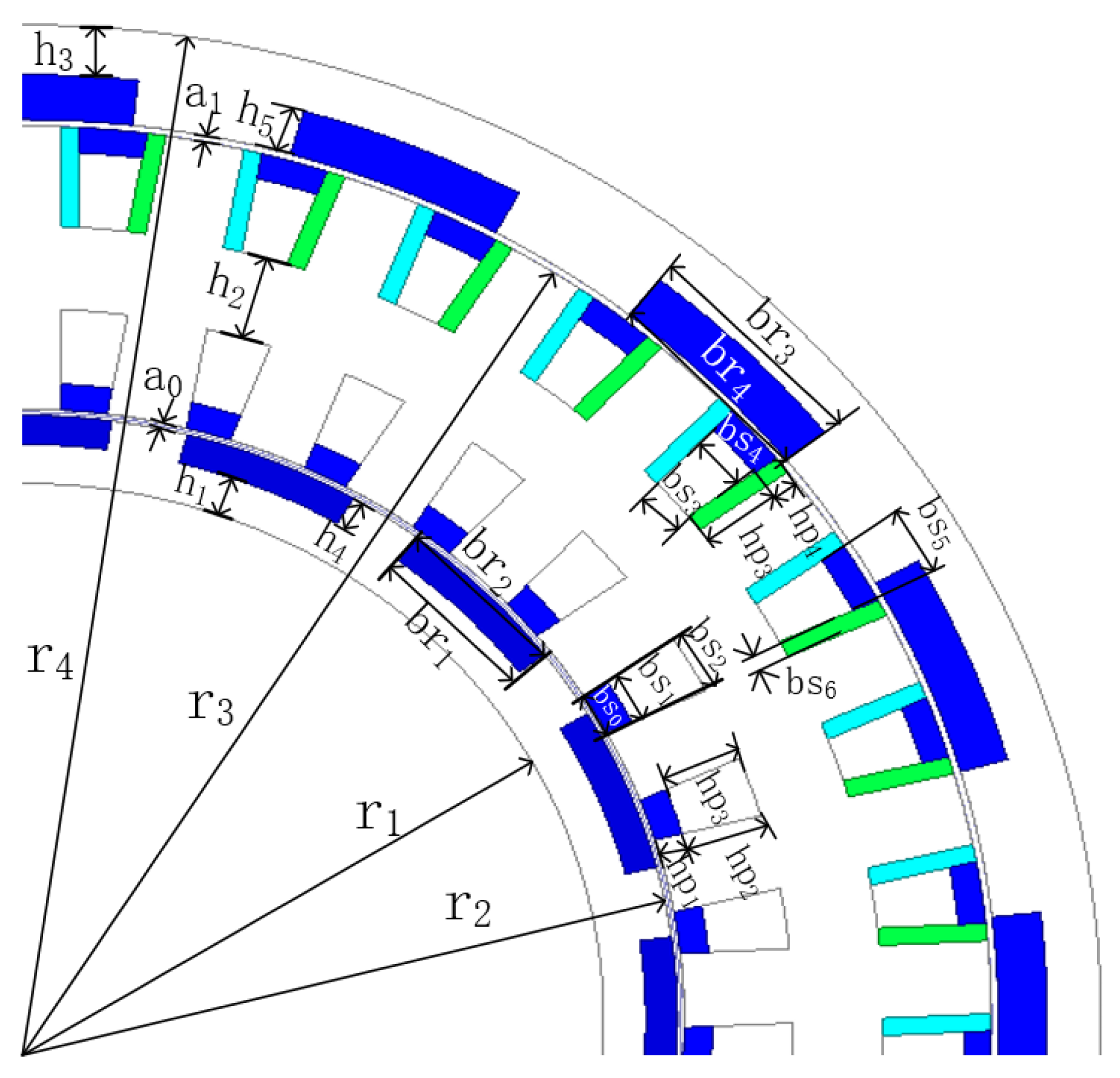
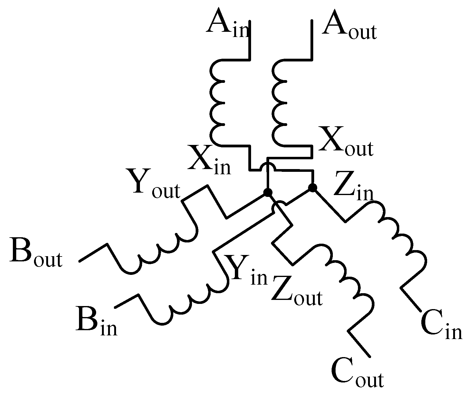
2.1. Machine Topology Design of the DSDRM

The overall schematic diagram and mechanical construction diagram of the proposed DSDRM are shown in Figure 1. The rear axle is shown in Figure 1b to connect the proposed DSDRM and the electric vehicle. The DSDRM is equipped with two stators and two rotors, and both rotors have cylindrical structures rigidly connected at the end of one side.
Consequently, the inner rotor and outer rotor—which each have a set of 16 PMs mounted on the surfaces facing the stators—rotate synchronously, and the magnetization directions of the PMs of the inner and outer rotors are uniformly toward the center of each pole. The inner and outer stators are connected by an iron core to form a cylindrical structure. Each stator has 33 slots to accommodate three-phase armature windings. The axes of the three-phase armature windings of the inner and outer stators are in mutual coincidence. Additionally, the typical winding connection type of each stator and the DSDRM employs a wye connection. The general dimensional parameters of the proposed DSDRM are shown in Figure 2 and Table 1.

2.2. Operating Principle of the DSDRM
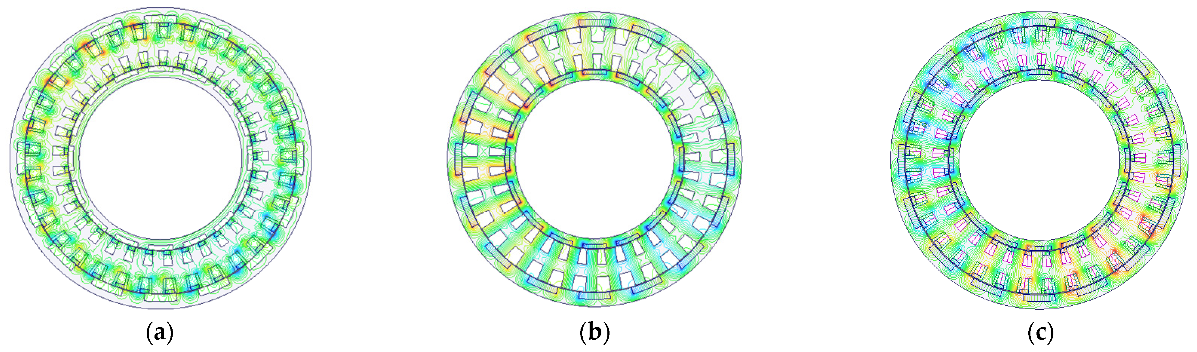
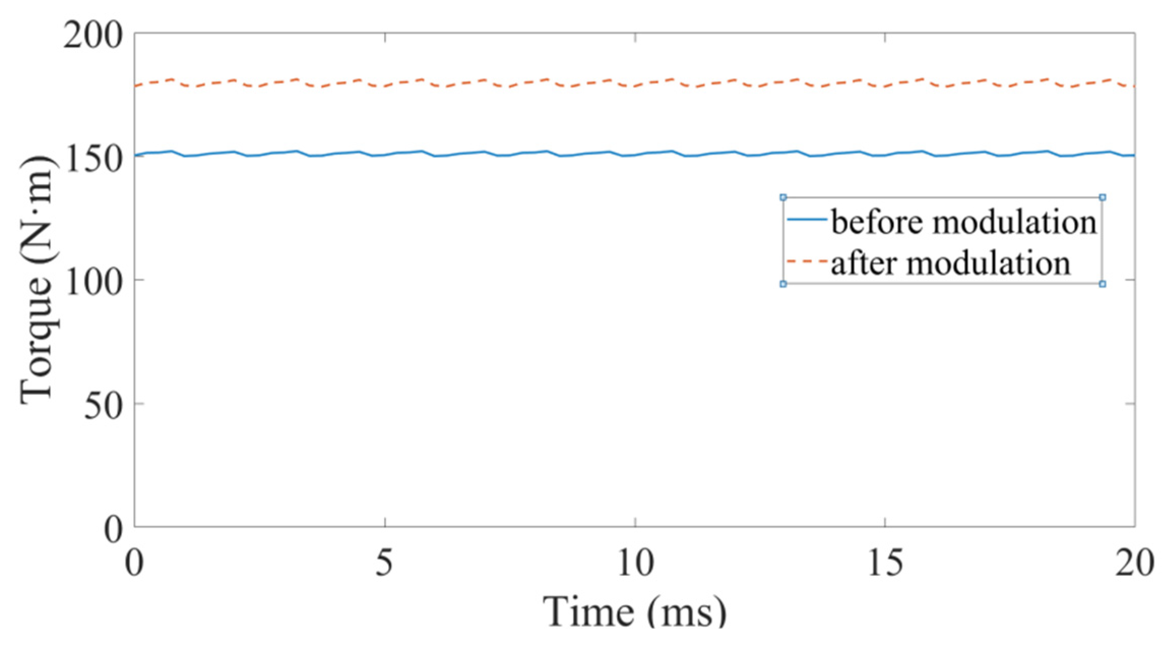
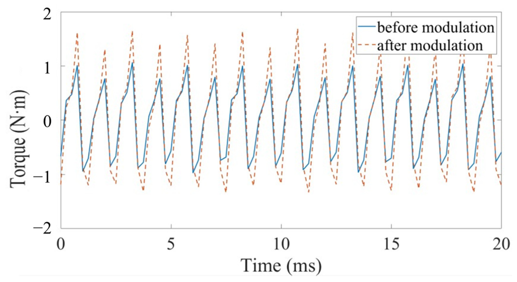
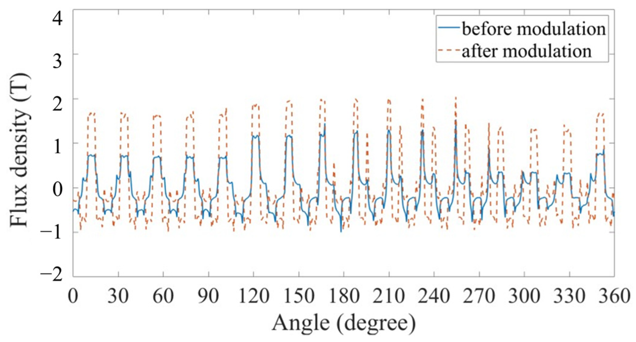
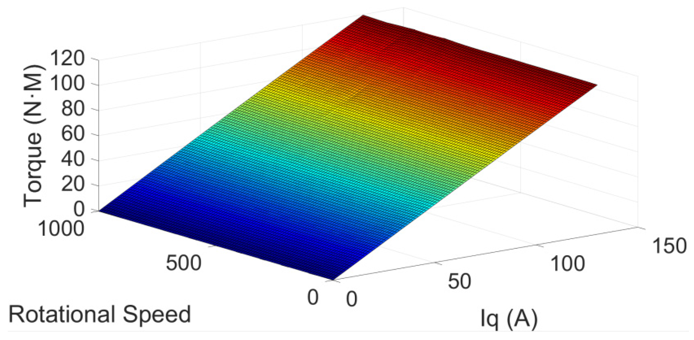
For the DSDRM, the principle of flux modulation is based on the operation of magnetic gear, which is expressed as follows:
p m , k = | m p + k n s |
where m = 1, 2, 3, …, ∞, k = 0, ±1, ±2, ±3, …, ±∞, p is the pole-pair number of the rotor, ns is the pole-pair number of the ferromagnetic pole, and pm,k represents the pole pairs of the space harmonic.
The combination (m = 1, k = −1) has the highest asynchronous space harmonic. Due to the magnetic gear rotor’s rotating speed being inversely proportional to the number of rotor pole pieces, the modulation principle is modified as follows:
m p ω 1 ± p m , k ω 2 k n s ω 3 = 0
where ω1, ω2, and ω3 are the rotational velocity of the rotor pole pieces, the ferromagnetic pole pieces, and the stator pole pieces, respectively.
For the DSDRM, the stator teeth replace the ferromagnetic pole pieces to carry out flux modulation, and the stator windings play the role of harmonic pole pieces. Therefore, the DSDRM modulation principle is modified as follows:
i Z 1 ω 1 ± Z 2 ω 2 j Z 3 ω 3 = 0
where Z1, Z2, and Z3 are the PM pole-pair number on the rotor, the three-phase armature windings’ pole-pair number, and the number of stator teeth, respectively, and i = 1, 2, 3, …, ∞ and j = 0, ±1, ±2, ±3, …, ±∞.
Firstly, the following section illustrates the working flux of the stator winding after the stator teeth modulation. The pole pairs should meet the following condition:
Z 2 = | i Z 3 + j Z 1 |
Since the stator teeth are stationary, ω3 = 0, and the rotational velocity of the flux density space harmonics is given as follows:
ω 2 = j Z 1 i Z 3 + j Z 1 ω 1
Secondly, the following section illustrates the working flux of the stator windings after the rotor teeth modulation. Their pole pairs should meet the following condition:
Z 2 = | i Z 1 + j Z 3 |
Since the stator teeth are stationary, ω3 = 0, and the rotational velocity of the flux density space harmonics is given as follows:
ω 2 = i Z 1 i Z 1 + j Z 3 ω 1
Since the combination (i = 1, j = −1) has the highest asynchronous space harmonic, both the rotational stator teeth and the rotor poles have the same speed. This confirms that the DSDRM accords with the bidirectional flux modulation effect. In this paper, the numbers of stator teeth of both the outer and inner stators of the DSDRM were set to be 33, and the numbers of outer and inner rotor teeth of the DSDRM were set to be 16. The pole-pair numbers of the three-phase armature windings among the outer and inner stators were set to be 17.

3. Simulations

Using the Taylor series stochastic finite element method (TS-FEM), the open-circuit field distributions of the proposed machine excited by PMs on rotors, PMs on stators, and both sets of PMs were investigated, as shown in Figure 3. It can be seen that the field excited by PMs on both rotors and stators is stronger than the one excited by PMs solely on stators or rotors.
The radial component of flux density of the inner and outer gaps, and the corresponding space harmonic spectrum, are shown in Figure 4 and Figure 5, respectively; due to the stator-PMs’ excitation, the numbers of space harmonic spectra are 17 and 33, respectively; similarly, with the rotor-PMs’ excitation, the numbers of space harmonic spectra are 17 and 16, respectively. In both cases, they exhibit the same 17 pole pairs in the air gap. Hence, two sets of PMs with winding excitation can rotate synchronously, and the proposed machine can transmit a stable torque. The simulation results match with the theoretical analysis.
To verify the effectiveness of the synthetic-slot structure, a comparison of the DSDRMs with and without PMs in stator slots was conducted based on TS-FEM simulations. The electromagnetic torque and torque ripple waveforms produced by the proposed DSDRM with and without synthetic slots are shown in Figure 6 and Figure 7, respectively. It can be seen that with only rotor-PMs’ excitation, before modulation, the machine can produce an average torque of up to 150.8 N·m, whereas with two sets of PMs’ excitation, after modulation, the machine can produce an average torque of 178.6 N·m. The cogging torque of the machine with stator-slot-embedded PMs is 1%—higher than that of the machine without stator-slot-embedded PMs (0.8%). However, the torque ripple is still very low when considering this new topology with high torque capability.
Figure 8 compares the air-gap field distributions due to rotor-PMs only with those due to both rotor- and stator-PMs. Correspondingly, Figure 9 shows the relationship between torque and the q-axis current iq at different rotational speeds.
In application, the currents of the inner stator windings and the outer stators should be in phase to produce maximum torque. Thus, the in-phase windings’ series connection type can be employed to reduce the number of electrical ports of the DSDRM, as indicated in Figure 10, and the back EMF waveforms of inner and outer windings after the in-phase windings’ series connection type at a rotational speed of 300 r/min are shown in Figure 11.

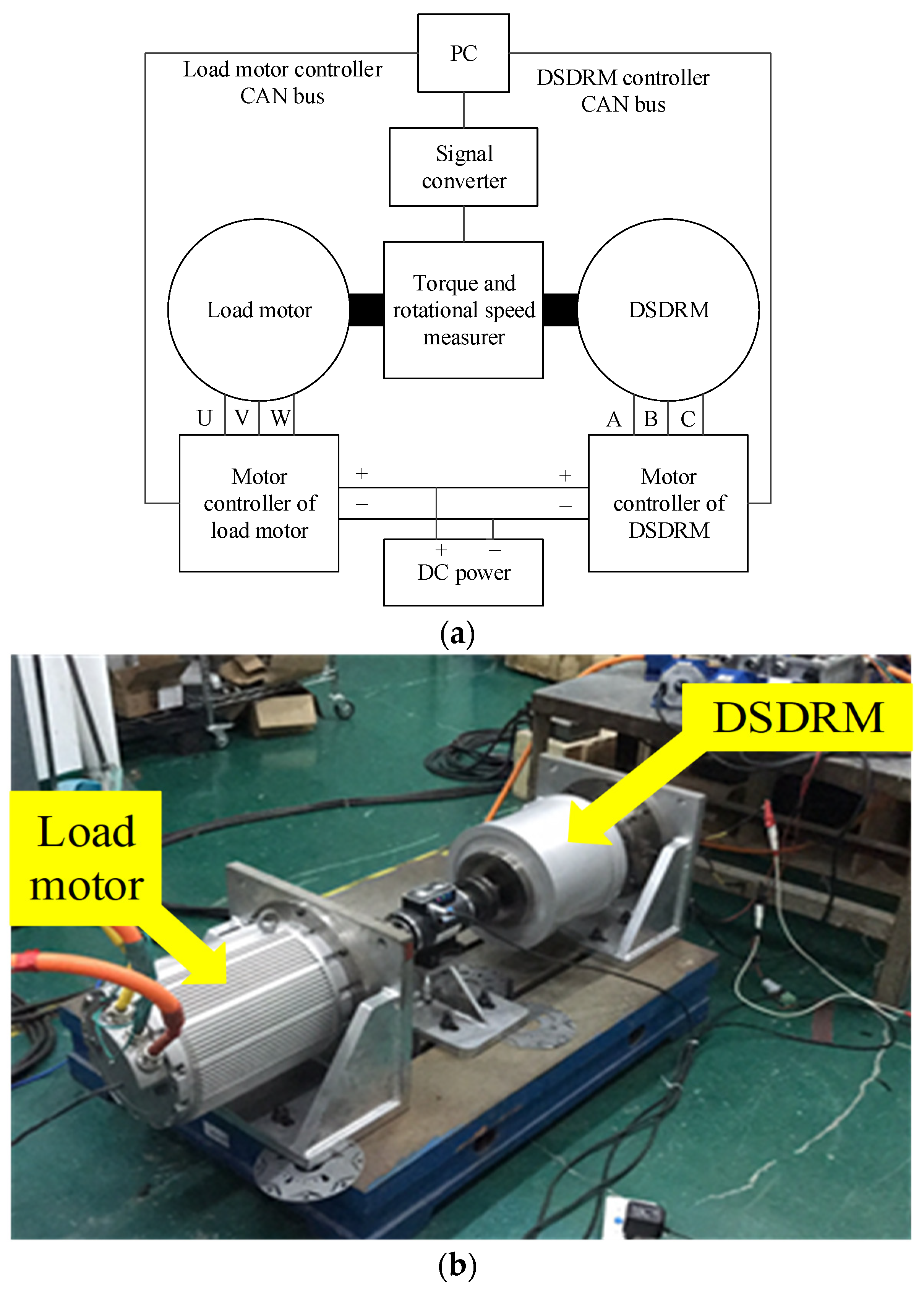
4. Experimental Verification

In order to verify the correctness of the theoretical analysis and simulation results, a prototype of the proposed DSDRM was fabricated, as shown in Figure 12. Figure 13a,b show the schematic block diagram and physical diagram of the test bench, respectively. Table 2 shows the information of the materials and weight of the proposed DSDRM. The calibration system comprises the DSDRM as the test motor, the load motor, the motor control units (MCUs) of the load motor, the MCUs of the DSDRM, the torque, a rotational speed measurer, and a direct current (DC) power supply.
Figure 14 shows the peak-to-peak value of the winding voltages at a rotor speed of 300 r/min. Compared with the simulation results in Figure 11, the peak-to-peak value of the experimental back EMF of DSDRM at a rotary speed of 300 r/min is approximately 77 V, and the peak-to-peak value of the simulated back EMF of the outer and inner windings at a rotary speed of 300 r/min is approximately 78 V. This indicates that the simulation results are consistent with the experimental testing.

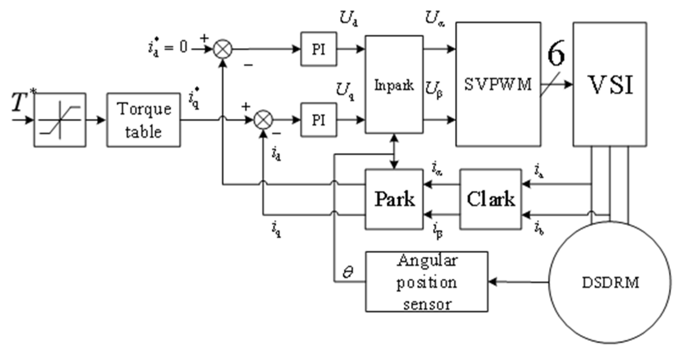
4.1. DSDRM Control System

A torque control method based on field-oriented control (FOC) was adopted to control the prototyped DSDRM. The drive system receives torque commands from other devices in the EV and translates them to the given q-axis currents iq by referring to the torque table, whereas the d-axis current id is set to zero to reduce the copper loss. Figure 15 shows the common torque control scheme for the DSDRM, which adopts the in-phase winding series connection type. PI control is widely used in process and motion control because of its simplicity, robustness, and reliability.
Using a torque and rotational speed measurer, a torque table can be established by measuring the actual output torque of the DSDRM at different speeds and q-axis currents. The calibration data obtained at 100 r/min are shown in Table 3.
The efficiency map of the proposed DSDRM is illustrated in Figure 16 based on practical testing; the maximum efficiency of the DSDRM is ~85%. This is less than that of the traditional PMSM, because the modulation of the magnetic field results in abundant space harmonics and increases iron consumption.

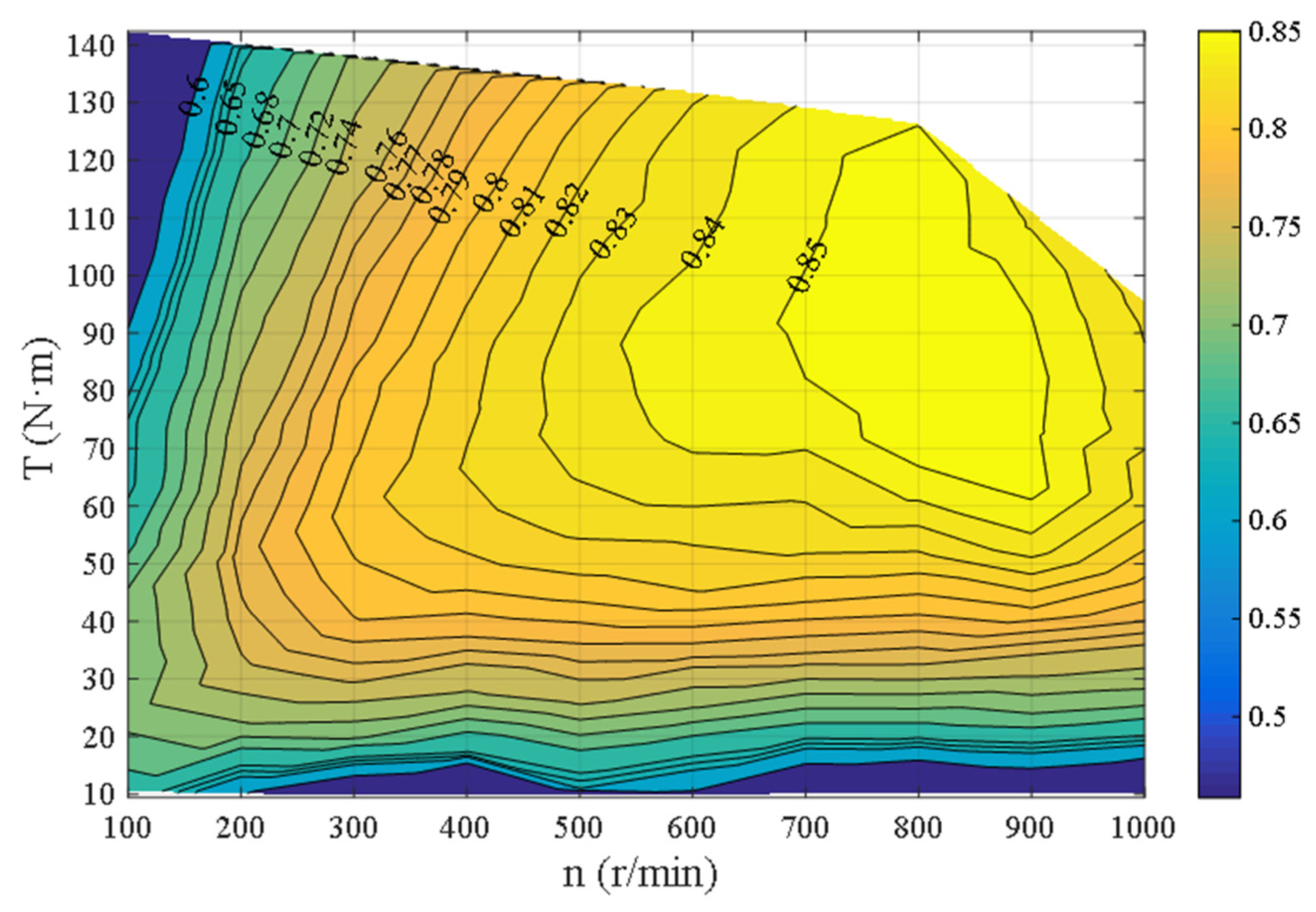
4.2. Vehicle Test with DSDRM

For the vehicle test, an EV containing the DSDRM drive system was designed. As shown in Figure 17a, the designed EV’s principal components are a vehicle control unit (VCU), a power distribution unit (PDU), a battery pack with a battery management system, and two DSDRM drive systems, each containing an MCU and a DSDRM. The hub is installed directly on the motor. The vehicle layout with the DSDRM is presented in Figure 17b.
The VCU receives gear and throttle information and converts it into a torque command, which is subsequently transmitted to two motor controllers through the MCU controller area network (CAN bus). When the EV moves, the VCU converts the throttle signals into torque commands, and transmits them to the drive systems of the left and right DSDRMs through the MCU CAN bus. Both operate at the torque loop, and output the electromagnetic torque to drive the EV frame [18].
The linear horizontal acceleration of the EV can be calculated using
a = ( T l e f t + T r i g h t ) r f m
where α is the acceleration; m is the weight of the EV, including the test driver, and is approximately 550 kg; f is the total resistance; r is the radius of each rear wheel (approximately 0.31725 m); and Tright and Tleft are the output torque of the left and right DSDRM, respectively.
The torque command conveyed to each drive system is the same, and is limited to 50 N·m. Thus, each DSDRM can output a maximum torque of 50 N·m, and the maximum total torque of the EV is 100 N·m. If f is assumed to be zero, the theoretical maximum linear acceleration of the designed EV is approximately 0.115 m/s2. The EV accelerates linearly with maximum torque on the horizontal plane.
Vehicle road test results are shown in Figure 18. Initially, the EV takes approximately 22 s to accelerate from 0 to 10 km/h. The average acceleration is approximately 0.11 m/s2. This is consistent with the theoretical results.
As shown in Figure 18, the proposed DSDRM has a rapid dynamic response in terms of the torque, which can reach the peak output torque in seconds and maintain a stable output torque capability. After the forward acceleration, a deceleration condition is shown between 30 and 40 s, indicating effective deliverability of the DSDRM. Finally, reverse deceleration is also provided for verifying the effectiveness of the DSDRM and its control technology.

5. Conclusions

A new DSDRM with a bidirectional flux modulation effect for in-wheel direct drive of EVs, employing a synthetic-slot structure, was proposed and investigated in this paper. According to the analysis and design results, the principle prototype of the motor and drive system was designed and manufactured, and the motor control strategy was designed. Comparative analysis by simulation and experiments verified that the proposed machine design is feasible. Finally, a detailed layout of an EV with the DSDRM was presented and verified by a vehicle road test experiment, providing a reference for the development of in-wheel direct drive systems.

Author Contributions

Conceptualization, C.L. and X.G.; methodology, J.F.; software, J.F. and R.W.; validation, C.L., J.F. and X.G.; formal analysis, H.C. and Z.L.; investigation, C.L. and J.F.; resources, X.G.; data curation, C.L. and J.F.; writing—original draft preparation, C.L. and J.F.; writing—review and editing, Y.L.; visualization C.L.; supervision, W.F.; project administration, X.G.; funding acquisition, X.G. All authors have read and agreed to the published version of the manuscript.

Funding

This work was supported in part by the Xiamen Science and Technology Project, =, under Grant 3502Z20203037, in part by the Science and Technology Innovation Team of Fujian Province Universities (Industrialization Project)–Power Semiconductor Device and Electric Drive Technology Innovation Team, under Grant 605-5J120019, and in part by the National Science Foundation of China, under Grant 52175051.

Institutional Review Board Statement

Not applicable.

Informed Consent Statement

Not applicable.

Data Availability Statement

All the data are shown in the tables and figures of this paper.

Conflicts of Interest

The authors declare no conflict of interest.

References

  1. Xiong, L.; Yu, Z. Control Allocation of Vehicle Dynamics Control for a 4 In-Wheel-Motored EV. In Proceedings of the 2nd International Conference on Power Electronics and Intelligent Transportation System, Shenzhen, China, 19–20 December 2009; pp. 307–311. [Google Scholar]
  2. Chen, Q.; Liao, C.; Ouyang, A.; Li, X.; Xiao, Q. Research and development of in-wheel motor driving technology for electric vehicles. Int. J. Electr. Hybrid Veh. 2016, 8, 242. [Google Scholar] [CrossRef]
  3. Inthamoussou, F.A.; Pegueroles-Queralt, J.; Bianchi, F.D. Control of a Supercapacitor Energy Storage System for Microgrid Applications. IEEE Trans. Energy Convers. 2013, 28, 690–697. [Google Scholar] [CrossRef]
  4. Geng, J.B.; Ji, Q. Multi-perspective analysis of China’s energy supply security. Energy 2014, 64, 541–550. [Google Scholar] [CrossRef]
  5. Fan, Y.; Zhang, Q.; Wang, W.; Zhou, X.; Wu, Z. Speed Regulation System of a Flux-Modulated Permanent-Magnet In-Wheel Motor Based on Sliding Mode Control and Adaptive Notch Filter. IEEE Trans. Energy Convers. 2018, 33, 2183–2190. [Google Scholar] [CrossRef]
  6. Liu, X.; Rui, Z.; Zhu, H.; Wang, J. Modeling method for battery distribution path optimization of EV charging and swapping service network. Electr. Power Autom. Equip. 2015, 35, 10–16. [Google Scholar]
  7. Sebastian, T. Temperature effects on torque production and efficiency of PM motors using NdFeB magnets. IEEE Trans. Ind. Appl. 1995, 31, 353–357. [Google Scholar] [CrossRef]
  8. Guo, X.; Wu, S.; Fu, W.; Liu, Y.; Wang, Y.; Zeng, P. Control of a Dual-Stator Flux-Modulated Motor for Electric Vehicles. Energies 2016, 9, 517. [Google Scholar] [CrossRef] [Green Version]
  9. Chau, K.T.; Zhang, D.; Jiang, J.Z.; Liu, C.; Zhang, Y. Design of a Magnetic-Geared Outer-Rotor Permanent-Magnet Brushless Motor for Electric Vehicles. IEEE Trans. Magn. 2007, 43, 2504–2506. [Google Scholar] [CrossRef] [Green Version]
  10. Wang, Y.; Niu, S.; Fu, W. Electrical-Continuously Variable Transmission System Based on Doubly Fed Flux-Bidirectional Modulation. IEEE Trans. Ind. Electron. 2017, 64, 2722–2731. [Google Scholar] [CrossRef]
  11. Atallah, K.; Rens, J.; Mezani, S.; Hove, D. A Novel “Pseudo” Direct-Drive Brushless Permanent Magnet Machine. IEEE Trans. Magn. 2008, 44, 4349–4352. [Google Scholar] [CrossRef]
  12. Liu, Y.; Fu, W.N.; Guo, X.; Li, Z.; Fang, R. A Dual Permanent Magnet Machine for High-Torque Low-Speed Applications. In Proceedings of the 20th International Conference on Electrical Machines and Systems (ICEMS), Sydney, Australia, 11–14 August 2017; pp. 1–4. [Google Scholar]
  13. Jian, L.; Chan, C.C.; Shi, Y.; Liu, C.; Xu, G.; Gong, Y. A Novel Dual-Permanent-Magnet-Excited Machine for Low-Speed Large-Torque Applications. IEEE Trans. Magn. 2013, 49, 2381–2384. [Google Scholar] [CrossRef]
  14. Wang, Q.; Niu, S.A. Novel Hybrid-Excited Dual-PM Machine with Bi-directional Flux Modulation. IEEE Trans. Energy Convers. 2017, 32, 424–435. [Google Scholar] [CrossRef]
  15. Amara, Y.; Vido, L.; Gabsi, M.; Hoang, E.; Ben Ahmed, A.H.; Lecrivain, M. Hybrid Excitation Synchronous Machines: Energy-Efficient Solution for Vehicles Propulsion. IEEE Trans. Veh. Technol. 2009, 58, 2137–2149. [Google Scholar] [CrossRef]
  16. Fu, W.N.; Ho, S.L.A. Quantitative Comparative Analysis of a Novel Flux-Modulated Permanent-Magnet Motor for Low-Speed Drive. IEEE Trans. Magn. 2009, 46, 127–134. [Google Scholar] [CrossRef]
  17. Xie, K.; Li, D.; Qu, R.; Gao, Y. A Novel Permanent Magnet Vernier Machine With Halbach Array Magnets in Stator Slot Opening. IEEE Trans. Magn. 2017, 53, 7207005. [Google Scholar] [CrossRef]
  18. Ma, Y.; Zhang, K.; Gu, J.; Li, J.; Lu, D. Design of the Control System for a Four-Wheel Driven Micro Electric Vehicle. In Proceedings of the IEEE Vehicle Power and Propulsion Conference, Dearborn, MI, USA, 7–10 September 2009; pp. 1813–1816. [Google Scholar]
Figure 1. The basic diagram: (a) overall structure; (b) mechanical construction diagram.
Machines 10 00027 g001
Figure 2. General parameters of the DSDRM.
Machines 10 00027 g002
Figure 3. Open-circuit field distributions due to PMs: (a) solely by stator-PMs; (b) solely by rotor-PMs; (c) by both rotor-PMs and stator-PMs.
Machines 10 00027 g003
Figure 4. Radial PM flux density distributions in the air gap: (a) outer air gap; (b) inner air gap.
Machines 10 00027 g004
Figure 5. Spectra of the radial PM flux density distributions in both air gaps: (a) outer air gap; (b) inner air gap.
Machines 10 00027 g005
Figure 6. Comparison of electromagnetic torque waveforms.
Machines 10 00027 g006
Figure 7. Comparison of cogging torque waveforms.
Machines 10 00027 g007
Figure 8. Comparison of PM flux density distribution waveforms.
Machines 10 00027 g008
Figure 9. Relationship between torque and q-axis current iq at different rotational speeds.
Machines 10 00027 g009
Figure 10. The in-phase winding series connection type of the DSDRM.
Machines 10 00027 g010
Figure 11. Simulation of three-phase back EMF waveforms at 300 r/min.
Machines 10 00027 g011
Figure 12. Prototype and verification platform of the DSDRM: (a) rotor; (b) stator; (c) prototype.
Machines 10 00027 g012
Figure 13. Verification system: (a) test schematic block diagram; (b) verification platform.
Machines 10 00027 g013
Figure 14. Experimental three-phase back EMF waveforms at 300 r/min.
Machines 10 00027 g014
Figure 15. DSDRM control scheme.
Machines 10 00027 g015
Figure 16. Measured efficiency map of the proposed DSDRM.
Machines 10 00027 g016
Figure 17. DSDRM direct-drive test system: (a) overall diagram; (b) vehicle layout with the DSDRM.
Machines 10 00027 g017
Figure 18. Vehicle road test results.
Machines 10 00027 g018
Table 1. General parameters of the DSDRM.
SymbolItemsValue
r1Inner radius of inner rotor64.7 mm
r2Outer radius of inner rotor72.9 mm
r3Inner radius of outer rotor108.6 mm
r4Outer radius of outer rotor120 mm
h1Height of inner rotor yoke4.7 mm
h2Height of stator yoke10 mm
h3Height of outer rotor yoke6 mm
h4Height of inner rotor PMs3.5 mm
h5Height of outer rotor PMs5.4 mm
br1Bottom width of inner rotor PMs19.08 mm
br2Top width of inner rotor PMs20.04 mm
br3Bottom width of outer rotor PMs25.97 mm
br4Top width of outer rotor PMs24.74 mm
bs0Open width of inner stator PMs5.05 mm
bs1Top width of inner stator slots5.64 mm
bs2Bottom width of inner stator slots7.36 mm
bs3Open width of outer stator slots5.25 mm
bs4Top width of outer stator slots6.96 mm
bs5Top width of outer stator crosswise PMs7.54 mm
bs6Width of outer stator lengthways PMs2.08 mm
hp1Height of inner stator PMs3.11 mm
hp2Height of inner stator slots9 mm
hp3Height of outer stator slots9 mm
hp4Height of outer stator crosswise PMs3.02 mm
a0Inner air-gap length0.75 mm
a1Outer air-gap length0.75 mm
Table 2. Information on the proposed DSDRM machine.
ContentMaterialDensity (g/cm3)Weight (kg)
Motor CaseAluminum2.721.136
Steel7.855.435
MagneticSintered Nd-Fe-B6.02.608
WindingRefined copper8.92.183
ScrewIron7.860.242
Total 31.604
Table 3. Calibration test data at 100 r/min.
Rotational Speed (r/min)iq(A)Torque (N·m)
10000
100109.6
1002022.3
1003038.7
1004053.2
1005069.1
1006079.3
1007099.9
10080109.3
10090128.3
Publisher’s Note: MDPI stays neutral with regard to jurisdictional claims in published maps and institutional affiliations.

