Article

Design and Optimization of High-Pressure Water Jet for Coal Breaking and Punching Nozzle Considering Structural Parameter Interaction

1
School of Mechanical Engineering, Yanshan University, Qinhuangdao 066004, China
2
School of Mechanical and Electrical Engineering, North China Institute of Aerospace Engineering, Langfang 065000, China
3
College of Mining Engineering, North China University of Science and Technology, Tangshan 063210, China
*
Author to whom correspondence should be addressed.
Machines 2022, 10(1), 60; https://doi.org/10.3390/machines10010060
Submission received: 15 December 2021 / Revised: 11 January 2022 / Accepted: 12 January 2022 / Published: 14 January 2022
(This article belongs to the Special Issue Optimization and Flow Characteristics in Advanced Fluid Machinery)

Abstract

:
The technology of increasing coal seam permeability by high-pressure water jet has significant advantages in preventing and controlling gas disasters in low-permeability coal seam. The structural parameters of a nozzle are the key to its jet performance. The majority of the current studies take strike velocity as the evaluation index, and the influence of the interaction between the nozzle’s structural parameters on its jet performance is not fully considered. In practice, strike velocity and strike area will affect gas release in the process of coal breaking and punching. To further optimize the structural parameters of coal breaking and punching nozzle, and improve water jet performance, some crucial parameters such as the contraction angle, outlet divergence angle, and length-to-diameter ratio are selected. Meanwhile, the maximum X-axis velocity and effective Y-axis extension distance are used as evaluation indexes. The effect of each key factor on the water jet performance is analyzed by numerical simulation using the single factor method. The significance and importance effect of each factor and their interaction on the water jet performance are quantitatively analyzed using the orthogonal experiment method. Moreover, three optimal combinations are selected for experimental verification. Results show that with an increase in contraction angle, outlet divergence angle, and length-to-diameter ratio, the maximum X-axis velocity increases initially and decreases thereafter. The Y-direction expansion distance of the jet will be improved significantly with an increase in the outlet divergence angle. Through field experiments, the jet performance of the improved nozzle 3 is the best. After optimization, the coal breaking and punching diameter of the nozzle is increased by 118%, and the punching depth is increased by 17.46%.

1. Introduction

An increase in coal mining depth results in an increase in in-situ stress and gas pressure, thereby resulting in gas accumulation in local areas. Consequently, the threat of gas disasters has increased substantially, and gas prevention and control have become increasingly difficult. Gas extraction is one of the main technical measures to prevent and control gas disasters. At present, the common methods of increasing coal seam permeability include deep-hole blasting, rotary hydraulic hole drilling, and dense long-hole drilling, which play a positive role in preventing gas disasters in low-permeability coal seam [1,2,3]. However, these methods are limited by a variety of conditions, including such problems as narrow scope of application and high cost. Accordingly, high-pressure water jet technology to punch coal has emerged, which has the advantages of high safety factor, low energy consumption, and low cost compared with other pressure relief anti-reflective technology [4,5,6]. High-pressure water jet technology has been successfully applied in Pingdingshan, Kailuan, Fengfeng, and other mining areas of low-permeability coal seam, thereby accumulating considerable field application.
As the executing element of a high-pressure water jet system, the nozzle converts the pressure energy of the water into the kinetic energy of the water jet, and shoots out in the form of a high-speed water jet to break and punch the coal; therefore, the nozzle is one of the core components of the entire system. In recent years, local and international scholars have conducted substantial research on the structural parameters and working conditions of coal breaking and punching nozzle that affect water jet performance [7,8,9,10]. Wen et al. [11] conducted a theoretical analysis and numerical simulation of computational fluid dynamics (CFD) to study the water jet performance of nozzles, particularly cone-straight nozzles, with different flow channel shapes. They performed an orthogonal experiment to determine the nozzle structure parameters when the water jet performance was optimal. Li et al. [12] used the finite element method (FEM) and smooth particle–fluid dynamics (SPH) to investigate the rock-breaking performance of a self-excited oscillating pulsed waterjet (SOPW). They likewise determined the mechanism of crack formation, and propagation and formation of the fracture zone, and analyzed the effects of pulse amplitude, pulse frequency, and pulse circumference on the rock-breaking ability. Chen et al. [13] used the CFD numerical simulation method to calculate a fully developed submerged impingement water jet, and studied the flow field structure and velocity distribution of the jet under different impact angles. Mohammad, Huang et al. [14,15] conducted a numerical simulation and experiment to study the influence of the nozzle exit shape on jet velocity, cluster property, and central impact force. Liu et al. [16] conducted an experiment on SC-CO2 jet coal breaking based on conical convergent and Laval nozzles, and concluded that the latter had a higher energy conversion rate and a stronger coal breaking effect than the former. They also determined that expansion ratio was the key factor affecting the jet performance of the Laval nozzle. Zhang et al. [17] studied the characteristics of complex unsteady flow when pulsed jet impinges on the rotating wall using the W-A turbulence model. They concluded that when the water hammer effect occurs, the impact pressure of a pulsed jet on the impacting wall is greater than that of a continuous jet in a certain period. Yang et al. [18] numerically analyzed a square centroid nozzle and found an optimal shrinkage degree at the nozzle outlet, thereby leading to a strong cavitation phenomenon in the jet and improving the performance of the cavitation jet. Hong et al. [19] proposed a method of using nitrogen gas as an abrasive jet medium for coalbed methane mining. Their experiments indicated that the nozzle diameter and target distance are the key factors in improving the performance of nitrogen jet coal breaking. Qiang et al. [20] used the DPM model to study particle movement trajectory in an abrasive water jet, and concluded that a high particle inlet position and a large convergence angle of the focus tube can improve jet performance and prolong the service life of the nozzle. Wang et al. [21] utilized the W-A turbulent model as a basis in analyzing the effects of water jets with different impinging heights on the flow field characteristics, and impinging pressure of submerged impinging. They concluded that the maximum velocity of the axis decreases rapidly with the increase in impact height, but the impact height has a minimal effect on the velocity of the wall jet zone. Peng et al. [22] analyzed the internal flow characteristics of the slurry pump under the conditions of clear water and solid–liquid two-phase by the Euler–Euler multiphase flow model. Ekiciler et al. [23] studied the influence of surface shape on impinging jet performance at different Reynolds numbers, and concluded that for small Reynolds numbers, a sinusoidal corrugated surface has a higher performance evaluation criterion (PEC). Liu et al. [24] investigated the effects of cutting depth and water pressure on rock-breaking performance using a conical pick assisted by an abrasive water jet (AWJ). The results show that a conical pick can efficiently break hard rock when assisted by the strong impact of an AWJ, which can provide a reference for practical application. Chen et al. [25] measured the shock parameters of a coal–water medium with different mass concentrations and obtained the effect of coal particle diameter on shock pressure and shock distance.
At present, a straight-taper or conical nozzle is mostly used as a punching nozzle for breaking coal. Moreover, the related research has mainly focused on nozzle inner flow- channel shape, contraction angle, outlet diameter, and other factors [26,27,28,29]. The experimental method is likewise relatively simple, the effect of the interaction of various factors on the experiment index is not considered, and the effective strike area is excluded in the evaluation index.
The reminder of this study is organized as follows: In Section 2, the construction features and principle of the nozzle are introduced, and two evaluation indexes of the X-axis velocity and effective Y-axis extension distance are proposed. In Section 3, the effect of key structural parameters on water jet performance is studied by single factor method and CFD numerical simulation, and the corresponding results are analyzed and discussed. In Section 4, the significance of key structural parameters and their interaction on water jet performance are further analyzed by the orthogonal experiment, and three structure combinations of the nozzle with better jet performance are selected. In Section 5, field experiments are carried out on the selected nozzles to verify the correctness of the theoretical analysis. Finally, the main conclusions are drawn, and the future work is prospected in Section 6.

2. Construction Features and Principle

The conical or cone-straight nozzle has good hydraulic performance, such as good jet bunching and energy concentration. Furthermore, they are machined conveniently, so are widely used in water jet cutting and impact technology. The structure of coal breaking and punching nozzle in this study is shown in Figure 1. In general, the design parameters of the nozzle are based on empirical values [30], the contraction angle is set to 12°–14°, and the length-to-diameter ratio is set to 2 to 4. However, the total length of the nozzle in actual production is limited owing to limitations of construction conditions and of water jet equipment. Hence, the water jet effect of the nozzle designed according to the empirical value is not ideal. According to the field experiment in the early stage, the inlet diameter of all nozzles studied in this paper is D = 10   mm , the outlet diameter is d = 2   mm and the length of outlet divergence angle l = 1   mm . Of particular note is l = 0   mm when the outlet divergence angle γ = 0 , other specific parameters are shown in Table 1, and the formula for L is as follows:
L = D 2 cot θ 2 d 2 cot θ 2
The research shows that when a continuous water jet impinges vertically on the surface of an object, it actually converts the kinetic energy of the water jet into dynamic pressure, that is, the stagnation pressure P s . Furthermore, P s is the direct force of the crushing development of the object [31,32]:
P s = 1 2 ρ ν 2
where, ρ is the density of the water (kg/m3), and ν is the propagation speed of the water (m/s).
The following conclusion can be drawn from formula (1): fluid velocity is one of the important indexes for breaking objects, and also a significant evaluation index of water jet performance. This study selects the maximum X-axis velocity of a water jet 100 mm away from the end face of the nozzle outlet as the first quantitative evaluation index. Moreover, this research refers to the attenuation of the axis velocity of water jet in the flow field. Given that the axis velocity attenuation is extremely complicated, quantitative analysis is difficult to conduct and such an attenuation should not be used as a sole specific evaluation index.
The stagnation pressure describes the force per unit area. In addition, the effective expansion characteristic of the water jet in the horizontal water jet field is also an important indicator of the water jet performance, which represents the effective impact area of the water jet. Given that the numerical model in this study is axisymmetric, the extension distance of the Y-axis was calculated according to the method of Azad et al. [33], specifically by selecting the data with a velocity attenuation within 15% of the target distance of 100 mm, which can be used as the second quantitative evaluation index of water jet performance.

3. Effect of Key Structural Parameters on Water Jet Performance

3.1. Computational Model

Water jet is a multiphase flow problem. A relatively large flow field calculation area outside the nozzle should be established to accurately reflect the actual water jet performance. In this paper, CFD is used to simulate the process of water jet which is produced by the coal breaking and punching nozzle impact on the target plate surface.
The effect of key structural parameters on the water jet performance is explored through the impact effect of different nozzles’ water jets, and then the structural parameters can be optimized. In this CFD numerical simulation, the injection distances are all set to 200 mm. In addition, the ICEM software is used for meshing, and the FLUENT software is used for setting parameters and computing.
Given that the computational grid has a significant effect on the time and accuracy of the CFD numerical simulation, the computational model is divided into parts, namely nozzle and flow field, [34] and divided by the hybrid grid technology. Inside the nozzle, the structure size is small, local pressure is large, and turbulence is intense. Hence, an unstructured grid is used to divide the nozzle. The external flow field is large and has a regular shape, and is divided by structured grids, thereby ensuring calculation accuracy and saving on calculation time.
According to the characteristics of the model, the nozzle’s inlet is set to pressure-inlet, and inlet pressure is 20 MPa. The outer flow field boundary is set to pressure-out, except for the rightmost boundary, and pressure is set to 1 atmosphere. The rightmost boundary and other boundaries of the flow field are set to wall. Given that the process of high-pressure water jet is ejected from the nozzle’s outlet into the air, turbulent diffusion and momentum exchange will occur between the water and ambient air. Air at the boundary is sucked in by the water jet, and droplets are “torn apart” by aerodynamic forces. As they have different velocities, the mixture model of the multiphase flow model is selected for numerical simulation. The main and second phases are set to air and water, respectively, and the transient and implicit pressure solvers are used for calculation. The two-equation model of RNG k-ε is the best choice for this study, which can clearly simulate the separation, secondary, swirl, and other complex flows in the water jet; a simple algorithm is used in this research to solve the coupling of pressure and velocity [35,36,37]; the computational model is shown in Figure 2.

3.2. Numerical Simulation

In the CFD simulation analysis, grid size has a substantial effect on the accuracy of results. To ensure the accuracy of results, the initial nozzle model was taken as the experiment object to obtain the best grid size. Grid sizes are set to 0.2, 0.3, 0.4, and 0.5 mm. Figure 3 shows the velocity distribution of the flow field under different grid sizes. Note that velocity distribution at the nozzle outlet and flow field change with an increase in grid size. Velocity distribution within the 0–100 mm target distance of the outflow field is shown in Table 2. Analysis indicates that when grid size is 0.2–0.3 mm, velocity changes of the flow field are the same, which has minimal effect on the calculation results. Although the calculation result is considerably accurate when the grid size is 0.2 mm, the calculation cost will increase several times compared with when the grid size is 0.3 mm. Therefore, the water jet performance of coal breaking and punching nozzle is eventually simulated and analyzed with a grid size of 0.3 mm. The structural parameters selected in this section are shown in Table 1.

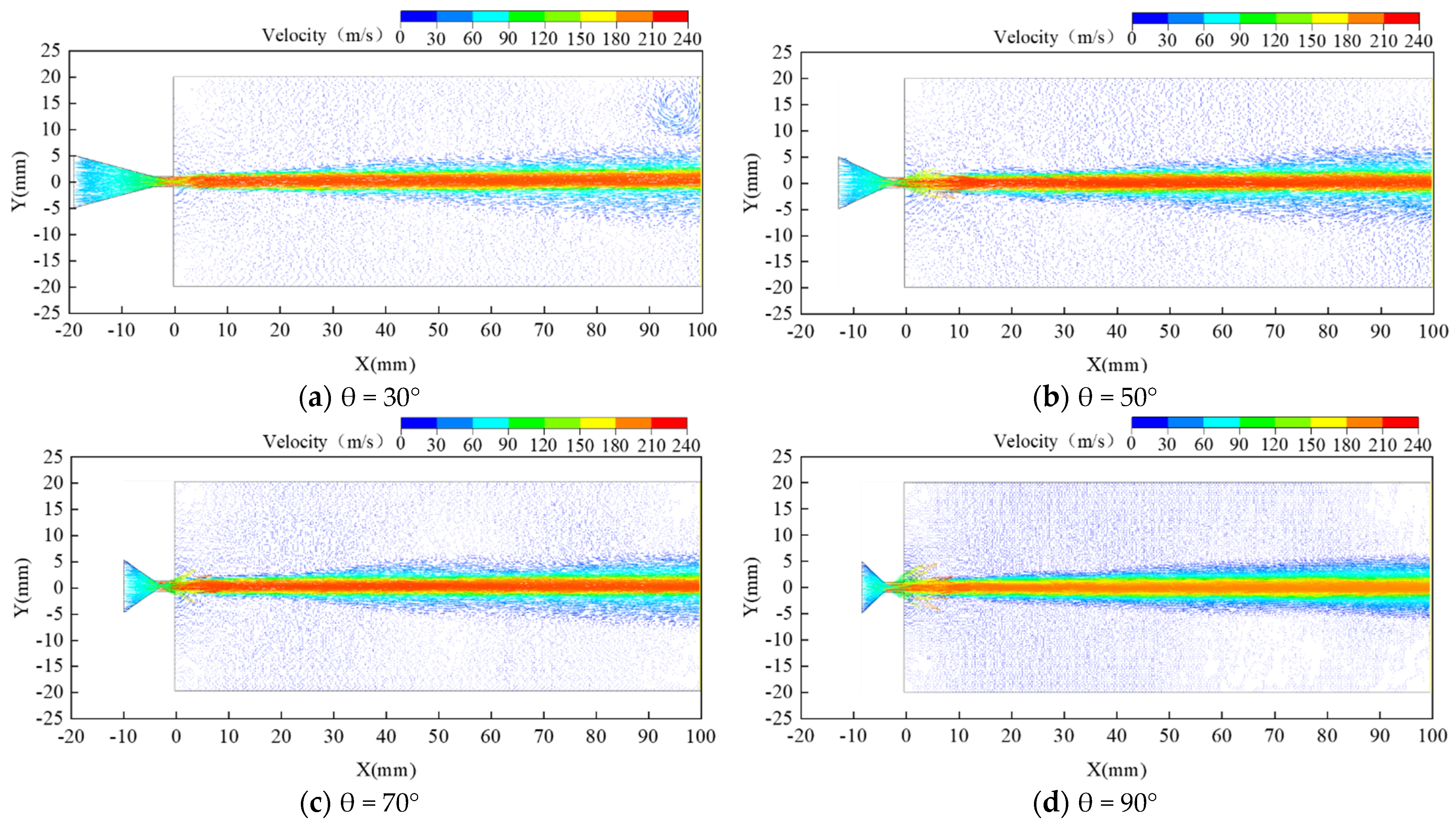
3.2.1. Effect of Contraction Angle on Water Jet Performance

To explore the effects of the previously mentioned three key structural parameters on the water jet performance of coal breaking and punching nozzle, the single factor method is used for simulation analysis. Under the condition that other parameters are the same, the value of contraction angle is changed, and the specific value is shown in Table 2.
When contraction angle increases, the maximum velocity at the nozzle exit increases significantly. When contraction angle is 50°, outlet velocity reaches the maximum value of 203.95 m/s. Outlet velocity decreases as contraction angle continues to increase, but the velocity is still higher than the contraction angle θ = 30°, as shown in Figure 4. When the target distance is below 100 mm, the X-axis velocity of water jet attenuation is slowest with the contraction angle θ = 30°, and its X-axis velocity is evidently higher than that of other contraction angles. Within a 40-mm target distance, the X-axis velocity of the water jet of the nozzle with contraction angle θ = 70° is higher than that of the nozzle with contraction angle θ = 30°. However, within the target distance of 40–100 mm, the X-axis velocity of the water jet of the two contraction angles is the same. Although the exit velocity of the nozzle is larger when the contraction angle θ = 90°, the X-axis velocity of the water jet decays rapidly with an increase in the target distance, particularly in the first 100-mm target distance, which decays nearly linearly. In the range of 100–200-mm target distance, the X-axis velocity of the nozzles with four different contraction angles continues to decay. The X-axis velocity of the water jet of the nozzles with contraction angles θ = 30° and θ = 50° decreases gradually, and the X-axis velocity of the two nozzles remains the same. The X-axis velocity of the water jet of the two nozzles with contraction angles θ = 70° and θ = 90° attenuates sharply, and are evidently lower than those of the other two nozzles. When the target distance X = 100 mm, the maximum X-axis velocity increases initially and decreases thereafter with an increase in the contraction angle. When the contraction angles θ = 50° and θ = 90°, X-axis velocities are the maximum and minimum, respectively. When the contraction angles θ = 30° and θ = 70°, the X-axis velocity is the same.
When the contraction angle increases, the effective Y-axis extension distance of the water jet increases initially and decreases thereafter, as shown in Figure 5. When the contraction angle increases from 30° to 50°, the effective Y-axis extension distance of the water jet increases by 2.48%. However, when contraction angle increases from 50° to 70° and 90°, the Y-axis extension distance of the water jet decreases by 5.08% and 9.62%, respectively. An increase in the effective Y-axis extension distance can increase the effective punching area of the water jet.

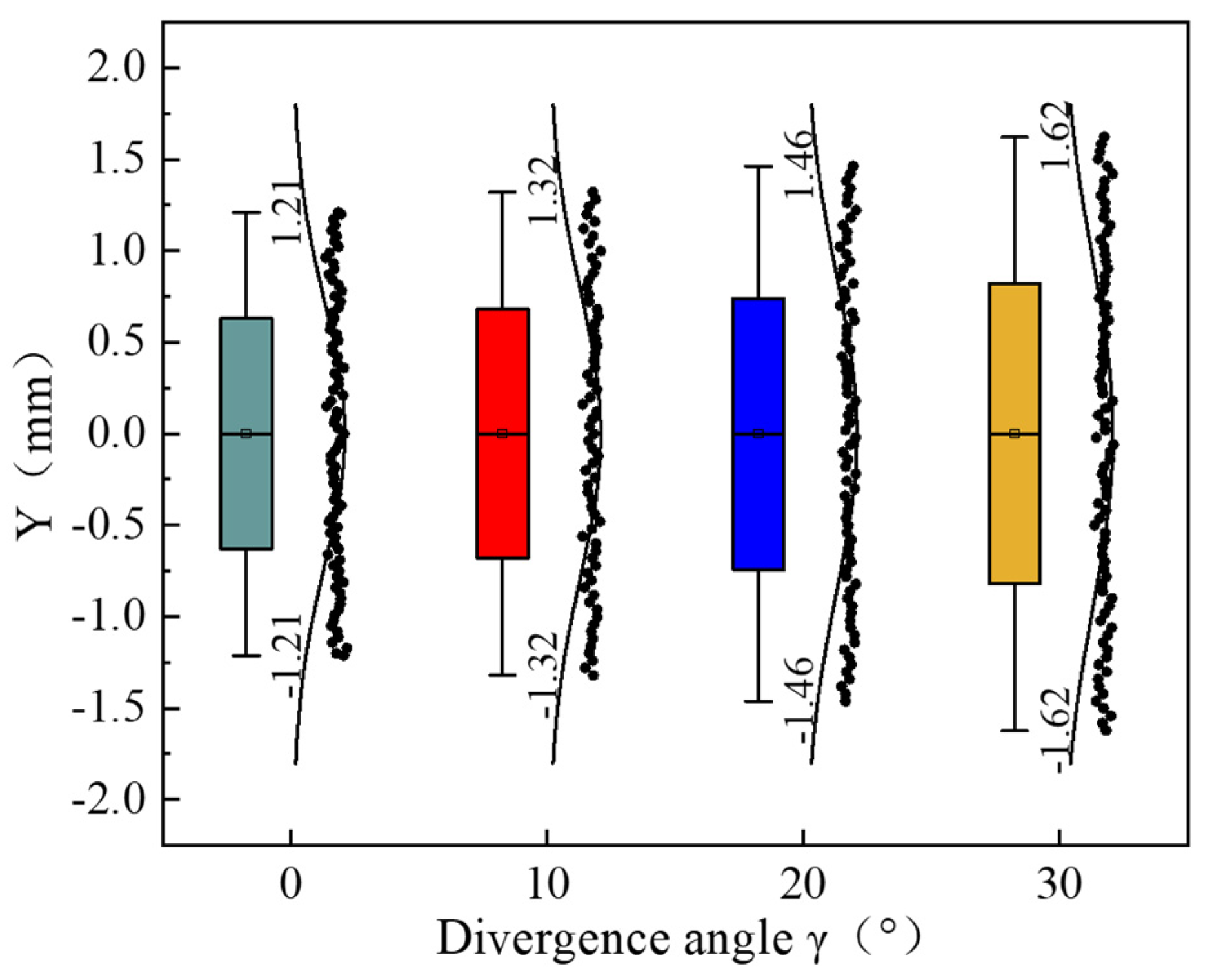
3.2.2. Effect of Outlet Divergence Angle on Water Jet Performance

To explore the effect of the divergence angle on the water jet performance of the nozzle, under the condition that the other parameters are the same, the value of the divergence angle is changed. The specific value is shown in Table 2.
The existence of the divergence angle makes the nozzle become a converging–diverging nozzle, and the outlet velocity increases significantly, as shown in Figure 6a. When the divergence angle γ = 0°, the outlet velocity of the water jet is 201.45 m/s. With an increase in the divergence angle, the outlet velocity of the water jet increases gradually. When the divergence angle γ = 30°, the outlet velocity of the water jet reaches 229.45 m/s, which is increased by 13.90% compared with that without the divergence angle. To better observe the change in the X-axis velocity of the water jet, the initial target distance starts from 20 mm, as shown in Figure 6b. With an increase in the divergence angle, the axis water jet velocity increases initially and decreases thereafter. In the whole flow field, the X-axis velocity of the water jet of the nozzle with divergence angle γ = 30° decays faster than that of other nozzles. Among the other three nozzles, the X-axis velocity of the nozzle with divergence angle γ = 10° is slightly higher. When the target distance is X = 100 mm, the sequence of velocity is as follows: γ = 10° > γ = 20° > γ = 0° > γ = 30°.
When there is an outlet divergence angle of the nozzle, the outlet diameter of the water jet increases, and the effective Y-axis extension distance of the water jet increases significantly. When the divergence angle γ = 30°, the effective Y-axis extension distance of the water jet reaches 3.24 mm, which is 33.88% more than that of the divergence angle γ = 0°. Moreover, the number of data points reaching the effective water jet velocity increases significantly, as shown in Figure 7.

3.2.3. Effect of the Length-to-Diameter Ratio on Water Jet Performance

Under the condition that the other parameters remain the same, the value of the length-to-diameter ratio is changed, and the specific value is shown in Table 2.
When the nozzle has no outlet cylindrical section, Figure 8 shows that the outlet and X-axis velocities of the water jet are significantly lower than those of the nozzle with an outlet cylinder. When the target distance exceeds 100 mm, the X-axis velocity of the water jet of the nozzle without an outlet cylinder decreases rapidly. When there is an outlet cylinder of the nozzle, outlet velocity of water jet increases initially and decreases thereafter with an increase in the length-to-diameter ratio. When l / d = 2.5 , the outlet velocity of the water jet is the largest, X-axis velocity attenuation is the slowest, and water jet performance is the best. When l / d = 2 and l / d = 3 , the X-axis velocity and attenuation of the water jet are the same. When the target distance is X = 100 mm, the X-axis velocity of the nozzle with outlet cylinder is considerably large, and maximum velocity is achieved when l / d = 2.5 . This result indicates that when some parameters are constant, there is an optimal length-to-diameter ratio to optimize the water jet performance.
The non-zero value of the length-to-diameter ratio will increase the effective Y-axis extension distance of the water jet. When the length-to-diameter ratio is l / d = 2.5 , the effective Y-axis extension distance is the maximum, which is increased by 8.3% compared with the minimum value, as shown in Figure 9. Note that the non-zero value of length-to-diameter increases the effective area of the water jet and improves the effects of coal breaking and punching.

3.3. Analysis and Discussion

In the process of jetting, the water jet will have a strong momentum exchange with the surrounding air, and increasing air will move forward with the water jet under the suction of the longitudinal vortex, making its axial speed continuously attenuated. With the involvement of air, jet flow will gradually increase and, in a certain range, will realize the increase in the effective Y-axis extension distance, thereby increasing the effective strike area. The change in the nozzle’s key structural parameters will affect the air entrainment rate of the water jet, and affect the jet effect thereafter.
When the contraction angle increases, flow resistance decreases, nozzle exit velocity increases, and high-speed water jet will have a strong entrainment effect on the nearby air. When t = 0.02   ms , the water jet has just squirted out, and with an increase in contraction angle, the maximum vortex of the jet moves backward and the front of the jet fans out and spreads around, as shown in Figure 10a–c. When the contraction angle is 90°, the nozzle exit velocity is considerably large, air entrainment rate is the largest, and the air volume fraction of the jet is the highest, thereby attaining the axial velocity attenuation fastest. Figure 10d shows that the air around the jet indicates a scattered strong volume of suction state, the consistency of the fluid moving forward is poor, and the front end of the jet is strongly disturbed. When t = 0.8   ms , the jet has been injected into the middle of the flow field, as shown in Figure 11. At this point, the velocity vector distribution of the flow field outside the nozzle of θ = 30° and θ = 50° is similar. When θ = 70° and θ = 90°, the air entrainment rate at the front end of the jet is substantially large. When t = 2   ms , the jet has been injected to the end of the flow field, as shown in Figure 12. That is, the larger the injection angle, the more evident the effect on air coiling. The air coiling rate of the entire flow field can be expressed by the volume fraction of air in the jet, as shown in Figure 13.
A comparison of Figure 4 and Figure 13 shows that the axial velocity decay of the water jet is negatively related to the volume fraction of air in the water jet. The larger the volume fraction, the more momentum exchange between the water jet and the air, and the more rapid the velocity decay. When the volume fraction of air is large, the Y-axis extension distance of the water jet will increase accordingly. For coal breaking and punching, only when the velocity reaches a certain level can an effective striking force be formed. This study calculates the effective Y-axis extension distance within a 15% decay of the Y-axis velocity. Figure 5 shows that an effective Y-axis extension distance does not increase constantly, although the larger the contraction angle, the higher the air roll absorption rate.
When there is an outlet divergence angle of the nozzle, a converging–diverging-type nozzle will form, resulting in a certain cavitation effect and significantly increasing the exit velocity. Moreover, an increase in the divergence angle will also reduce the wall attachment effect of the water jet, thereby further enhancing the exit velocity and producing strong entrainment to the surrounding air, and changing the jet effect. When the divergence angle is changed, the volume fraction of air in the water jet is shown in Figure 14. A comparison of Figure 6, Figure 7 and Figure 14 indicates that the larger the divergence angle, the higher the air enrolling rate. Moreover, axial velocity attenuation increases. However, the presence of the divergence angle increases the nozzle exit velocity. Thus, the effective Y-axis extension distance remains considerably large when the target distance X = 100 mm.
The presence of an outlet cylindrical section of the nozzle will play a certain stabilizing effect on the water jet, thereby reducing the turbulent flow pattern and improving the water jet cluster effect. Consequently, the axial velocity attenuation is reduced. However, when the cylindrical length is markedly long, flow resistance will increase, thereby reducing the exit velocity. When the length-to-diameter ratio is changed, the volume fraction of air in the water jet is shown in Figure 15. Figure 8 and Figure 9 show an optimal length-to-diameter ratio, which makes the water jet to air volume absorption rate considerably moderate, thereby obtaining superior axial velocity and an effective Y-axis extension distance.

4. Orthogonal Experiment

To obtain the optimal combination of nozzle structural parameters when the X-axis velocity and effective Y-axis extension distance of the water jet are the largest, a numerical simulation and an orthogonal experiment are performed to further study the relationship among key parameters and their effects on water jet performance. According to the preceding analysis results, three good levels are selected for each factor. Factors A, B, and C are the contraction angle, divergence angle, and length-to-diameter ratio, respectively. The specific values are shown in Table 3.

4.1. Experiment Design

In the study of the effect of nozzle key structural parameters on water jet performance, the effect of the interaction between various factors on the experiment index is fully considered. Combined with research rules and practical principles, the first-order interaction between factors is mainly investigated in this study. According to the number of selected factors, the orthogonal experiment table of L27 (313) was selected to make a reasonable arrangement for all factors in the experiment. The experimental data are shown in Table 4. In particular, single factors A, B, and C are placed in columns 1, 2, and 5, respectively. Moreover, A × B is in columns 3 and 4, A × C is in columns 6 and 7, and B × C is in columns 8 and 11. The interaction of the three factors A × B × C is placed in columns 9, 10, 12, and 13, and is taken as the error. When the target distance is X = 100 mm, the maximum X-axis velocity and effective Y-axis extension distance of the water jet are selected as inspection indexes. Given that the model is axisymmetric, the effective Y-axis extension distance is replaced by a half-value.

4.2. Results and Discussion

4.2.1. Range Analysis of the Orthogonal Experiment

In the orthogonal experiment, the degree of effect of the different factors on the results is often compared through the intuitive analysis method–range method, and the range value R can be calculated using Formula (3) [38,39]. The greater the R value, the greater the effect of this factor on the results.
R = max ( T 1 , T 2 , T 3 ) min ( T 1 , T 2 , T 3 )
where, R is the range value and Ti (i = 1, 2, 3) represents the sum of the 9 experimental data corresponding to the ith level in each column.
According to the preceding formula, range analysis was conducted on the factors corresponding to the maximum X-axis velocity and effective Y-axis extension distance at the target distance of 100 mm and their first-order interaction. The results are shown in Table 5.
Range analysis indicates that the primary and secondary sequence of each factor and interaction is as follows for the maximum X-axis velocity:
A > B > A × B > C > A × C > B × C
For the effective Y-axis extension distance, primary and secondary sequences of each factor and interaction are as follows:
B > C > A > A × B > B × C > A × C

4.2.2. Variance Analysis of the Orthogonal Experiment

In the orthogonal experiment analysis, although the range analysis is simple, the effect of the experimental error on the results cannot be excluded, and the accuracy of the analysis cannot be verified. Therefore, the F function should be used to conduct variance analysis for each factor and the interaction between factors, further excluding the experimental error and exploring the effect of each factor on the index [40,41]. The F function is as follows:
F a ( n 1 , n 2 ) = F
where a is the significant level, n1 is the degree of freedom corresponding to each factor, and n2 is the sum of the degree of freedom of error.
When the significant level and degree of freedom are determined, the specific value of the F function can be obtained using the F distribution table [42]. In this experiment, F0.01 and F0.05 are taken as critical values. If F > F0.05 of a factor, then there is 95% confidence that this factor has a significant impact on the index value, which is statistically significant. If F > F0.01, then there is 99% confidence that this factor has a significant impact on the index value, which is highly statistically significant. In the variance analysis table of this paper, * * stands for highly significant and * stands for significant.
Factors A × C and B × C are close to the sum of the squares of the error column A × B × C. Thus, they are combined into the experimental error column, and a new sum of squares and degree of freedom are recalculated thereafter. The variance analysis of the maximum X-axis velocity is shown in Table 6.
Table 7 shows that the sum of the square of the factor A × C and error column A × B × C is close. Adding it to the error and the final results are as follows:

4.3. Comprehensive Analysis of Experimental Data Based on Orthogonal Experiment

According to the results of the orthogonal experiment, when the X-axis velocity is maximum, optimal levels of each factor are A2, B1, A2 × B1, C1, A2 × C1, and B1 × C1, comprehensively considering that A2 × B1 × C1 is the optimal combination. A nozzle of this structure is shown in the orthogonal experiment table, and the maximum X-axis velocity is 200.484 m/s at 100 mm. When the effective Y-axis extension distance is the largest, the optimal levels of each factor are B3, C2, A3, A3 × B3, B3 × C2, and A3 × C2. Hence, A3 × B3 × C2 is the optimal combination. A nozzle of this structure is shown in the orthogonal table, and its effective Y-axis extension distance is 3.204 mm.
Further analysis of the data in Table 4 shows that the maximum X-axis velocity and maximum effective Y-axis extension distance do not appear simultaneously, but the two evaluation indexes should be considered comprehensively in the process of high-pressure water jet breaking coal and punching. The effective Y-axis extension distance of the A2 × B1 × C1 combination is 2.484 mm, which is below that of other combinations. The maximum X-axis velocity of the A3 × B3 × C2 combination is 193.189 m/s, which is the lowest among the different combinations. Therefore, a comprehensive analysis of the results of the single factor method in Part 2 and orthogonal experiment method in Part 3 indicates that the combination of A2 × B2 × C2 is the optimal parameter combination of the water jet performance. At this point, the maximum X-axis velocity is 198.277 m/s, and effective Y-axis extension is 3.044 mm, which are relatively superior in their respective index values. The improved nozzles processed with the three parameter combinations will be verified by field experiments and compared with the original nozzle.

5. Field Experiments

To further verify the water jet performance after nozzle optimization, a water jet experiment was conducted in the Qianjiaying mining area of the Kailuan Group using the self-developed equipment of a high-pressure water jet. The schematic of the equipment and water jet performance are shown in Figure 16 and Figure 17, respectively.

5.1. Determination of Coal Firmness Coefficient

To eliminate the interference of other factors on the effect of coal breaking and punching and ensure the accuracy of the results, the firmness coefficient of the four wall surfaces selected in the punching experiment was measured. Taking wall 1 as an example, after removing the floating coal with a thickness of approximately 0.3 m on the surface, coal samples were collected in three locations: the upper left area of the coal wall, the area of the coal wall directly opposite of the high-pressure water jet equipment, and the upper right area of the coal wall. The coal samples are labeled A1, B1, and C1. According to the standard of the determination method of the coal firmness coefficient [43], the coal with label A1 is sampled and measured.
The three groups were measured in parallel at each position, and the arithmetic mean value of the 3 positions was taken as the final firmness coefficient of wall 1. Coal samples in other areas were also measured strictly according to the preceding method. The obtained data are shown in Table 8. The difference in the firmness coefficient within 0.86% indicates that the firmness coefficient of the selected three wall surfaces is consistent. According to the orthogonal analysis experiment results, the initial nozzle, the improved 1, improved 2, and improved 3 nozzles were arranged to perform coal breaking and punching experiments at walls 1, 2, 3, and 4, respectively, to further reduce experimental error.

5.2. Experimental Analysis

Before the coal breaking and punching experiment, the pressure of the pump was adjusted, and the nozzle inlet pressure was stabilized at 20 MPa according to the pressure gauge. The erosion time of each nozzle was 300 s. According to the analysis result in Part 3, three groups of parameters were selected to improve the nozzle. The field coal breaking and punching experiment is shown in Figure 18. The parameters of the nozzle and measured data are shown in Table 9. The punching depth is the maximum hole depth measured perpendicular to the punching end face. Given that all the holes are quasi-circular, the punching diameter is the arithmetic average of the maximum and minimum diameters.
According to the experimental data, compared with the initial nozzle, the punching depth and diameter of improved nozzles 1 and 2 has been significantly improved. However, the diameter and depth of punching cannot reach the maximum value simultaneously. The reason is that improved nozzle 1 is selected based on the maximum X-axis velocity, while improved nozzle 2 is selected based on the maximum effective Y-axis extension distance. This result also confirms that the two indexes represent the depth and area, respectively, of punching, which is consistent with the analysis result of the orthogonal experiment. Moreover, this result indicates the reliability of the orthogonal experiment. When the maximum X-axis velocity is optimal, punching depth is increased by 12.70% compared with the initial value. When the effective Y-axis extension distance is optimal, punching diameter is increased by 90.91% compared with the initial value. Note that improved nozzle 3 is worth focusing on, the maximum X-axis velocity and effective Y-axis extension distance of which are less than those of improved nozzles 1 and 2. However, the punching depth and punching diameter are optimal, which are 4.22% and 14.29% higher than the two nozzles on the punching depth and diameter, respectively. Both are improved by 17.46% and 118% compared with the initial nozzle. This result shows that punching depth and punching area are mutually affected. That is, when the punching depth deepens, it is easier to obtain a larger punching area. Similarly, when the punching area increases, it is easier to obtain a deeper punching depth. Therefore, to achieve the overall improvement of the water jet performance, the maximum X-axis velocity and effective Y-axis extension distance must be considered simultaneously. In future research, multi-parameter and multi-objective collaborative optimization of the nozzle can be conducted to improve the water jet performance comprehensively.

6. Conclusions

In this study, the effect of nozzle structure parameters on water jet performance is explored by CFD simulation and verified by field experiments. The research results provide a certain reference value for nozzle structure optimization. The major findings include:
(1) The key structural parameters of the nozzle have a significant impact on the performance of the water jet. Among the key parameters, the value of the contraction angle has the greatest impact on the maximum X-axis velocity, and the value of the divergence angle has the greatest impact on the effective Y-axis extension distance.
(2) Based on the comprehensive results of the orthogonal experiment, range analysis, and variance analysis, three optimal combinations of nozzle structural parameters are selected. Through the field experiment, the optimized nozzles can improve the coal breaking and punching ability of the water jet.
(3) The orthogonal experiment shows that interaction among multiple parameters will affect the water jet performance, and the X-axis velocity and effective Y-axis extension distance of nozzle do not reach the optimal value at the same time. According to the field experiment result in Part 4, the punching depth and area also affect each other. Therefore, in future research, multi-parameter and multi-objective collaborative optimization of the nozzle can be carried out to improve the water jet performance more comprehensively.

Author Contributions

Conceptualization, L.C.; Methodology, L.C.; Software, M.C.; Validation, L.G.; Formal analysis, Y.C.; Writing—original draft preparation, L.C. and M.C.; Writing—review and editing, L.C. and D.G.; Supervision, L.C. and D.G.; Funding acquisition, L.G. All authors have read and agreed to the published version of the manuscript.

Funding

This work was supported by the National Natural Science Foundation of China (Grant No.51874012).

Institutional Review Board Statement

Not applicable.

Informed Consent Statement

Not applicable.

Data Availability Statement

Not applicable.

Conflicts of Interest

The authors declare no conflict of interest.

References

  1. Shen, Z.H. Water Jet Theory and Technology; China University of Petroleum Press: Dongying, China, 1998. [Google Scholar]
  2. Chen, X.C.; Deng, S.S.; Guan, J.F.; Hua, W.X. Experiment and simulation research on abrasive water jet nozzle wear behavior and anti-wear structural improvement. J. Braz. Soc. Mech. Sci. Eng. 2017, 39, 2023–2033. [Google Scholar] [CrossRef]
  3. Njock, P.G.A.; Chen, J.; Modoni, G.; Arulrajah, A.; Kim, Y.H. A review of jet grouting practice and development. Arab. J. Geosci. 2018, 11, 459. [Google Scholar] [CrossRef]
  4. Singh, D.; Premachandran, B.; Kohli, S. Effect of nozzle shape on jet impingement heat transfer from a circular cylinder. Int. J. Therm. Sci. 2015, 96, 45–69. [Google Scholar] [CrossRef]
  5. Vinze, R.; Chandel, S.; Limaye, M.D.; Prabhu, S.V. Influence of jet temperature and nozzle shape on the heat transfer distribution between a smooth plate and impinging air jets. Int. J. Therm. Sci. 2016, 99, 136–151. [Google Scholar] [CrossRef]
  6. Zhang, X.Z.; Wiśniewski, P.; Dykas, S.; Zhang, G. Permeability enhancement properties of high-pressure abrasive water jet flushing and its application in a soft coal seam. Front. Energy Res. 2021, 9, 679623. [Google Scholar] [CrossRef]
  7. Chen, C.; Nie, S.L.; Wu, Z.J.; Li, Z.Y. A study of high pressure water jet characteristics by CFD simulation. Mach. Tool Hydraul. 2006, 2, 103–105. [Google Scholar]
  8. Wen, J.; Chen, C. Multifunctional experimental device of teaching model and its application of water jet testing and breaking rock. Sci. Technol. Eng. 2017, 17, 168–172. [Google Scholar] [CrossRef]
  9. Kong, L.; Wang, Y.; Lei, X.; Feng, C.; Wang, Z. Integral modeling of abrasive waterjet micro-machining process. Wear 2021, 482–483, 203987. [Google Scholar] [CrossRef]
  10. Nedelcu, D.; Cojocaru, V.; Avasiloaie, R.C. Numerical investigation of nozzle jet flow in a pelton microturbine. Machines 2021, 9, 158. [Google Scholar] [CrossRef]
  11. Wen, J.W.; Chen, C. Optimizing the structure of the straight cone nozzle and the parameters of borehole hydraulic mining for huadian oil shale based on experimental research. Energies 2017, 10, 2021. [Google Scholar] [CrossRef] [Green Version]
  12. Li, H.S.; Liu, S.Y.; Jia, J.G.; Wang, F.C.; Guo, C.W. Numerical simulation of rock-breaking under the impact load of self-excited oscillating pulsed water jet. Tunn. Undergr. Space Technol. 2020, 96, 179–192. [Google Scholar] [CrossRef]
  13. Chen, X.X.; Wang, C.; Shi, W.D.; Zhang, Y.C. Numerical simulation of submerged impinging water jet at different impact angles. J. Drain. Irrig. Mach. Eng. 2020, 38, 658–662. [Google Scholar]
  14. Rahman, M.S.; Tay, G.F.K.; Mark, F.T. Effects of nozzle geometry on turbulent characteristics and structure of surface attaching jets. Flow Turbul. Combust. 2019, 103, 797–825. [Google Scholar] [CrossRef]
  15. Huang, F.; Hu, B.; Zuo, W.Q.; Li, S.Q. Experiments on the impact pressure of high-pressure water jet under different nozzle shapes. J. Chongqing Univ. 2019, 42, 124–133. [Google Scholar]
  16. Liu, Y.; Cui, J.W.; Jian, P.; Liu, X.T. Effect of nozzle structure on coal breakage of SC-CO2 used for well drilling. Geomech. Geophys. Geo-Energy Geo-Resour. 2020, 6, 67. [Google Scholar] [CrossRef]
  17. Zhang, L.; Wang, C.; Zhang, Y.; Xiang, W.; He, Z.; Shi, W. Numerical study of coupled flow in blocking pulsed jet impinging on a rotating wall. J. Braz. Soc. Mech. Sci. Eng. 2021, 43, 496–508. [Google Scholar] [CrossRef]
  18. Yang, M.G.; Xiao, S.N.; Kang, C.; Wang, Y.L. Effect of geometrical parameters on submerged cavitation jet discharged from profiled central-body nozzle. Chin. J. Mech. Eng. 2013, 26, 476–482. [Google Scholar] [CrossRef]
  19. Hong, C.Y.; Yang, R.Y.; Huang, Z.W.; Liu, W.; Chen, J.X.; Cong, R.C. Experimental investigation on coal-breakage performances by abrasive nitrogen-gas jet with a conical nozzle. Int. J. Rock Mech. Min. Sci. 2021, 142, 104781. [Google Scholar] [CrossRef]
  20. Qiang, Z.R.; Wu, M.P.; Miao, X.J.; Rupy, S. CFD research on particle movement and nozzle wear in the abrasive water jet cutting head. Int. J. Adv. Manuf. Technol. 2018, 95, 4091–4100. [Google Scholar] [CrossRef]
  21. Wang, H.; Qian, Z.; Zhang, D.; Wang, T.; Wang, C. Numerical study of the normal impinging water jet at different impinging height, based on Wray-Agarwal turbulence model. Energies 2020, 13, 1744. [Google Scholar] [CrossRef] [Green Version]
  22. Peng, G.J.; Tian, L.; Hao, C.; Hong, S.M.; Ye, D.X.; You, B.J. Numerical and experimental study of hydraulic performance and wear characteristics of a slurry pump. Machines 2021, 9, 373. [Google Scholar] [CrossRef]
  23. Ekiciler, R.; Cetinkaya, M.S.; Arslan, K. Convective heat transfer investigation of a confined air slot-jet impingement cooling on corrugated surfaces with different wave shapes. J. Heat Transf. 2019, 141, 22202. [Google Scholar] [CrossRef]
  24. Liu, S.Y.; Zhou, F.Y.; Li, H.S.; Chen, Y.Q.; Wang, F.C.; Guo, C.W. Experimental investigation of hard rock breaking using a conical pick assisted by abrasive water jet. Rock Mech. Rock Eng. 2020, 53, 4221–4230. [Google Scholar] [CrossRef]
  25. Chen, J.; Guo, L.W.; Zhang, J.Y. Relationship between shock parameter and coal particle parameter of advanced premixed micro-soft abrasive coal-water jet. Powder Technol. 2021, 379, 393–406. [Google Scholar] [CrossRef]
  26. Fang, M.H.; Yu, T.; Feng, F.; Jeff, X. An experimental investigation of abrasive suspension flow machining of injector nozzle based on orthogonal test design. Int. J. Adv. Manuf. Technol. 2020, 110, 1071–1082. [Google Scholar] [CrossRef]
  27. Zhou, J.R.; Zhao, M.M.; Wang, C.; Gao, Z.J.; Zhu, Y. Optimal design of diversion piers of lateral intake pumping station based on orthogonal test. Shock. Vib. 2021, 2021, 6616456. [Google Scholar] [CrossRef]
  28. Zhu, Y.; Li, G.; Wang, R.; Tang, S.; Su, H.; Cao, K. Intelligent fault diagnosis of hydraulic piston pump combining improved lenet-5 and PSO hyper parameter optimization. Appl. Acoust. 2021, 183, 108336. [Google Scholar] [CrossRef]
  29. Wang, H.; Long, B.; Wang, C.; Han, C.; Li, L. Effects of the impeller blade with a slot structure on the centrifugal pump performance. Energies 2020, 13, 1628. [Google Scholar] [CrossRef]
  30. Shen, H.J. Structural optimization and test of nozzle for coal seam slotting. Saf. Coal Mines 2020, 51, 10–13. [Google Scholar] [CrossRef]
  31. Lu, Y.Y.; Huang, F.; Liu, X.; Ao, X. On the failure pattern of sandstone impacted by high-velocity water jet. Int. J. Impact Eng. 2015, 76, 67–74. [Google Scholar] [CrossRef]
  32. Yu, Y.F.; Li, C.X.; Meng, H.B.; Wang, Y.F.; Wu, J.H. Flow and entrainment characteristics of jet from different shape nozzles. Chin. J. Process Eng. 2014, 14, 549–555. [Google Scholar]
  33. Azad, M.; Quinn, W.R.; Groulx, D. Mixing in turbulent free jets issuing from isosceles triangular orifices with different apex angles. Exp. Therm. Fluid Sci. 2012, 39, 237–251. [Google Scholar] [CrossRef]
  34. Shi, L.; Zhu, J.; Tang, F.; Wang, C. Multi-Disciplinary optimization design of axial-flow pump impellers based on the approximation model. Energies 2020, 13, 779. [Google Scholar] [CrossRef] [Green Version]
  35. Wen, J.W.; Qi, Z.W.; Seyed, S.B.; Pei, X.J.; Tom, I. Research on the structures and hydraulic performances of the typical direct jet nozzles for water jet technology. J. Braz. Soc. Mech. Sci. Eng. 2019, 41, 558–570. [Google Scholar] [CrossRef]
  36. Chen, B.; Gao, D.R.; Li, Y.B.; Chen, C.Q.; Yuan, X.M.; Wang, Z.S.; Sun, P. Investigation of the droplet characteristics and size distribution during the collaborative atomization process of a twin-fluid nozzle. Int. J. Adv. Manuf. Technol. 2020, 107, 1625–1639. [Google Scholar] [CrossRef]
  37. Humaira, Y.; Naveed, I.; Anum, T. Engineering applications of peristaltic fluid flow with hall current, thermal deposition and convective conditions. Mathematics 2020, 8, 1710. [Google Scholar] [CrossRef]
  38. Wang, H.; Hu, Q.; Yang, Y.; Wang, C. Performance differences of electrical submersible pump under variable speed schemes. Int. J. Simul. Model. 2021, 20, 76–86. [Google Scholar] [CrossRef]
  39. Tang, S.; Zhu, Y.; Yuan, S. An improved convolutional neural network with an adaptable learning rate towards multi-signal fault diagnosis of hydraulic piston pump. Adv. Eng. Inform. 2021, 50, 101406. [Google Scholar] [CrossRef]
  40. Liang, B.J.; Gao, D.R. Optimization of structural parameters of fan—Shaped high-pressure nozzle. J. Drain. Irrig. Mach. Eng. 2020, 38, 69–75. [Google Scholar]
  41. Zhu, Y.; Li, G.; Wang, R.; Tang, S.; Su, H.; Cao, K. Intelligent fault diagnosis of hydraulic piston pump based on wavelet analysis and improved Alex Net. Sensors 2021, 21, 549. [Google Scholar] [CrossRef]
  42. He, W.; Xue, W.D.; Tang, B. Optimization Method of Experimental Design and Data Analysis; Chemical Industry Press: Beijing, China, 2012. [Google Scholar]
  43. GB/T 23561.12-2010; Methods for Determining the Physical and Mechanical Properties of Coal and Rock—Part 12: Methods for Determining Coal Hardiness Coefficient. Standards Press of China: Beijing, China, 2011.
Figure 1. Diagram of the coal breaking and punching nozzle structure.
Machines 10 00060 g001
Figure 2. Computational Model.
Machines 10 00060 g002
Figure 3. Velocity cloud of the flow field of different grid sizes.
Machines 10 00060 g003
Figure 4. Effect of contraction angle on the X-axis velocity attenuation of water jet.
Machines 10 00060 g004
Figure 5. Effect of contraction angle on the effective Y-axis extension distance of water jet at X = 100 mm.
Machines 10 00060 g005
Figure 6. Effect of divergence angle on the X-axis velocity attenuation of the water jet.
Machines 10 00060 g006
Figure 7. Effect of divergence angle on the effective Y-axis extension distance of the water jet at X = 100 mm.
Machines 10 00060 g007
Figure 8. Effect of length-to-diameter ratio on X-axis velocity attenuation of water jet.
Machines 10 00060 g008
Figure 9. Effect of length-to-diameter on the effective Y-axis extension distance of water jet at X = 100 mm.
Machines 10 00060 g009
Figure 10. Velocity vector of the flow field when t = 0.02   ms .
Machines 10 00060 g010aMachines 10 00060 g010b
Figure 11. Velocity vector of the flow field when t = 0.8   ms .
Machines 10 00060 g011
Figure 12. Velocity vector of the flow field when t = 2   ms .
Machines 10 00060 g012aMachines 10 00060 g012b
Figure 13. Effect of contraction angle on air volume fraction.
Machines 10 00060 g013
Figure 14. Effect of divergence angle on air volume fraction.
Machines 10 00060 g014
Figure 15. Effect of length-to-diameter on air volume fraction.
Machines 10 00060 g015
Figure 16. Schematic of the self-developed equipment of high-pressure water jet.
Machines 10 00060 g016
Figure 17. Performance of the water jet.
Machines 10 00060 g017
Figure 18. Coal breaking and punching experiment.
Machines 10 00060 g018
Table 1. Structure parameter of the nozzle.
Structure ParameterInlet Contraction Angle
θ (°)
Outlet Divergence Angle γ (°)Length-to-Diameter Ratio
l / d
Inlet Diameter
D (mm)
Outlet Diameter d (mm)
Initial nozzle3002102
Improved nozzle30, 50, 70, 9002102
300, 10, 20, 302102
3000, 2, 2.5, 3102
Table 2. Water jet velocity distribution of different grid sizes.
Grid Size (mm)Grid QuantityVelocity Distribution (m/s)
0.526,528198.0234–200.9876
0.441,419198.4325–201.0324
0.374,391199.9132–201.4522
0.2176,040199.9246–201.4703
Table 3. Level table of each factor.
LevelABC
θ (°)γ (°)l/d
13002
250202.5
370303
Table 4. Orthogonal experiment table L27 (313) and experimental data.
FactorsABABA2BCACA2CBCABCA2BCB2CAB2CA2B2CMaximum X-Axis Velocity (m/s)Half of Effective Y-Axis Extension Distance
(mm)
Experimental Number12345678910111213
130011211111111199.8651.212
2300112.522222222200.3931.303
330011333333333199.8791.221
4302022211222333199.8681.323
53020222.522333111199.4241.503
6302022333111222200.0241.402
7303033211333222198.3971.463
83030332.522111333198.1181.563
9303033333222111198.3501.532
1050023223123123200.4841.242
11500232.531231231199.3821.283
1250023312312312199.4261.281
13502031223231312199.1811.341
145020312.531312123198.2771.522
15502031312123231198.3901.401
16503012223312231197.1601.502
175030122.531123312198.4761.582
18503012312231123195.7481.441
1970032232132132198.3311.183
20700322.513213213198.9361.191
2170032321321321199.2251.101
22702013232213321195.7751.361
237020132.513321132195.6031.381
24702013321132213195.2841.321
25703021232321213188.2341.421
267030212.513132321193.1891.602
27703021321213132191.6061.522
Table 5. Range analysis of the water jet performance.
FactorsABCA × BA × CB × C
Maximum X-axis velocity (m/s)38.13536.64314.60318.1788.9676.934
Half of effective Y-axis extension distance(mm)0.5122.6110.8820.3170.2120.252
Table 6. Variance analysis of the maximum X-axis velocity.
Source of VarianceDeviation Sum of SquaresDegree of FreedomVarianceVariance RatioSignificant Level
A90.207245.103544.22725* *
B75.918237.95937.22155* *
C10.3225.165.059754*
A × B32.48248.12057.962738* *
A × C5.76541.44125
B × C5.34641.3365
A × B × C5.20680.65075
Error16.317161.019813
Sum255.24426
FaF0.05(2, 16) = 3.63, F0.05(4, 16) = 3.01, F0.05(8, 16) = 2.59
F0.01(2, 16) = 6.23, F0.01(4, 16) = 4.77, F0.01(8, 16) = 3.89
Table 7. Variance analysis of effective Y-axis extension distance.
Source of VarianceDeviation Sum of SquaresDegree of FreedomVarianceVariance RatioSignificant Level
A0.01720.008520.4* *
B0.38320.1915459.6* *
C0.04820.02457.6* *
A × B0.01140.002756.6* *
A × C0.00340.00075
B × C0.00640.00153.6*
A × B × C0.00280.00025
Error0.005120.000417
Sum0.47326
FaF0.05(2, 12) = 3.88, F0.05(4, 12) = 3.26, F0.05(8, 12) = 2.85
F0.01(2, 12) = 6.93, F0.01(4, 12) = 5.41, F0.01(8, 12) = 4.5
Table 8. Firmness coefficient of the coal wall.
Coal WallSample PositionFirmness Coefficient of Group 1Firmness Coefficient of Group 2Firmness Coefficient of Group 3Average of Firmness Coefficient
1A10.510.530.520.5222
B10.520.510.53
C10.520.520.54
2A20.530.520.520.5256
B20.520.530.54
C20.540.510.52
3A30.520.530.530.5244
B30.510.530.53
C30.520.510.54
4A40.520.520.530.5267
B40.530.530.54
C40.530.520.52
Table 9. Experimental results of coal breaking and punching before and after nozzle optimization.
Experimental GroupStructural ParametersPunching Depth
(m)
Punching Diameter
(m)
A (°)B (°)C
Initial nozzle30020.630.11
Improved 150020.710.15
Improved 270302.50.580.21
Improved 350202.50.740.24
Publisher’s Note: MDPI stays neutral with regard to jurisdictional claims in published maps and institutional affiliations.

