
A Digital Twin Model of Three-Dimensional Shading for Simulation of the Ironmaking Process

1
Department of Mechanical Engineering, Politecnico di Milano, 20156 Milan, Italy
2
School of Automation, Central South University, Changsha 410000, China
*
Author to whom correspondence should be addressed.
†
These authors contributed equally to this work.
Machines 2022, 10(12), 1122; https://doi.org/10.3390/machines10121122
Submission received: 17 October 2022
/
Revised: 21 November 2022
/
Accepted: 22 November 2022
/
Published: 27 November 2022
(This article belongs to the Special Issue 10th Anniversary of Machines—Feature Papers in Advanced Manufacturing)
Abstract
:Advanced manufacturing is a new trend for sustainable industrial development, and digital twin is a new technology that has attracted attention. Blast furnace smelting is an effective method in the manufacturing of iron and steel. Comprehensive and dependable surveillance of the blast furnace smelting process is essential for ensuring the smooth operation and improving of iron and steel output quality. The current technology makes it difficult to monitor the entire process of blast furnace ironmaking. Based on Unity 3D, this study presents a digital-twin virtual reality simulation system of blast furnace ironmaking. First, shading modeling creates a three-dimensional dynamic geometric model in different ironmaking system scenarios. Then, we script the animation and call particle system according to the motion mode of distinct geometric objects to give the dynamic effect of geometric objects. Shaders are the focus of the design and contributions. In addition, shader optimization technology can reduce hardware resource consumption and increase system fluency. Vertex shaders are used for all types of coordinate space transformation and vertex output; fragment shaders are used for texture sampling, light model calculation, normal calculation, noise superposition, and color output. The shader rendering technique allows for more realistic lighting effects. The presented dynamic digital twin system implements more realistic lighting analyzed in the ironmaking process. Virtual interaction logic’s design and deployment process is based on HTC VIVE hardware and VRTK toolkit. In the actual simulation process, the typical animation frame rate is stable at about 75 FPS (frames per second). The simulation system runs smoothly and a cutting-edge and state-of-the-art method for observing the blast furnace ironmaking process is suggested.
1. Introduction
Intelligent systems and virtual reality technology are currently hot topics that can revitalize the industry, increase companies’ competitiveness, and reduce production costs. It yields more intelligent manufacturing and production, which avoids safety hazards and improves profits. Iron and steel are one of the core sectors of the national economy, accounting for tremendous social and technological progress. Blast furnace smelting is the upstream process of steel manufacturing [1,2]; the blast is the primary emission link of iron and steel production, and the furnace is also the most energy-intensive process [3,4,5,6]. The environment of ironmaking blast furnaces is complicated and harsh, with high temperatures, high dust levels, and a high level of vibration interference [7,8,9]. The traditional operation style makes it impossible to observe the whole process of blast furnace ironmaking, and there is a possibility it causes a significant safety hazard to the workers and operators. It is critical to implement a technique and technology that can thoroughly and consistently replicate and monitor the blast furnace ironmaking process in real time. Based on the above analysis, this study presents a virtual reality simulation system based on digital twin and Unity 3-Dimension (3D), which is then deployed to the blast furnace ironmaking sector.
Virtual reality (VR) is a new graphics and image technology. It generates a three-dimensional simulation system, for users in visual, auditory, tactile, and other areas of communication and interaction using computer simulation [10,11]. The interaction between the user and the simulation system, as well as the user’s own perception and cognitive ability to touch the object, inspire the user inspiration, in order to thoroughly obtain the spatial information and logical information included in the system [12,13]. In the last decades, the digital twin has been a hot topic for international researchers, some of which have been applied to the non-ferrous and manufacturing industries. For instance, Zhou et al. investigated the collaborative optimization strategy for reducing energy, which develops the progress of ironmaking production [14]; however, the furnace blast efficiency is ignored by their digital twin method. Boschert et al. proposed the simulation aspect of the digital twin techniques, which gives a comprehensive review of the digital twin [15]. In [16], a novel digital twin dosing system for iron reverse flotation is proposed, and solves the flotation monitoring in iron production, although the large-scale process of ironmaking is not presented. Some other digital twin invariants can be also specified in concept review [17], iron bird design [18], cloud computing platform [19], potential analysis [20], and aluminum electrolysis process [7,19,21,22,23].
In recent years, the study of virtual reality simulation systems has been the hottest topic and has received a lot of attention. DarPA has been working on virtual battlefield technologies since the 1980s. Foreign virtual reality simulation system development is currently pretty developed. In recent years, the virtual reality simulation system has been quickly expanded, for example, by being used in medical, education, manufacturing, design, and other industries, and a number of achievements have been made [24,25,26]. Burdea et al., for instance, provides a full introduction to virtual reality technology, including the source, development, and future directions [10]. Zenner et al. established an immersive process model to investigate the interplay of a virtual and cyber-physical world [13].
Immersion, interactivity, multisensory, conceptualization, autonomy, and authenticity are all qualities of a VR simulation system. Shader technology is one of the technologies that have an impact on authenticity. One purpose of shader technology is to replace the existing non-programmable fixed rendering process with a programmable rendering pipeline. Fixed rendering pipelines or texture mapping is used to create traditional light and shadow effects; however, these approaches are restricted to texture mapping and the physical attributes of the model object itself, and their flexibility is limited, rendering effect is difficult, and authenticity has to be further enhanced. Depending on the shader technology, the rendering details of the graphics can be controlled by controlling the rendering pipeline, so that more rich and realistic lighting effects can be expected. Since shader technology improves light and shadow effects, research on shader technology is of great significance to animation production, film special effects realization, virtual reality product development, and other aspects. In addition, shader technology mainly uses graphics processing unit (GPU) rendering, which brings users a more efficient rendering solution, namely GPU rendering solution.
The digital twin has been the hottest topic that emerged in the past several years [21,22,26,27,28]. It constructs a full lifespan situation of some industrial processes and then monitors and makes some abductive analysis for the whole fault diagnosis. The digital twin shading render can also prevent some fault happens at an early age. Recently, digital twin technology has been applied to some specific domains [29,30,31,32]. For instance, Liu et al. proposes a reuse and evaluation approach for smart process planning [31]. In [32], a novel intelligent manufacturing model is proposed for the non-ferrous metal industry; however, this is only a basic partnership of the digital twin; the applicability of the ironmaking process has yet to be researched. Because iron production is a complicated industrial process, it is impacted by several elements during the manufacturing process. Huang et al. proposes a unified framework for the production validation of digital twin development, it gives insight into the advanced manufacturing cutting-edge application [33]. He et al. also reviewed the sustainable aspect of intelligent manufacturing, which motivates that the novel technology has a brilliant future [34]. Lopez et al. summarizes the event-triggered platform with the real-time application [35]. Guo et al. utilized the digital twin technology to promote the layout optimization for the discrete workshop [36]. Roy et al. gives a comprehensive analysis of the digital twin development in the manufacturing process with specific cases, their study greatly motivated our ironmaking work [37]. Liu et al. considered the digital twin’s reuse and evaluation policy, and proposed the process planning method, which can be significantly promoted [38]. Yu et al. evaluated the VR technology with the industrial Internet of Things and its corresponding protection; however, their approach is a theoretical analysis without practical verification [39]. Motivated by this literature, this paper proposes a digital twin 3D shading to blast the ironmaking process. The main contributions of this paper are given as follows.
- A digital twin model is proposed for observing the whole production process. The presented method implemented the virtual reality and shading rending of the whole ironmaking furnace process. The computation performance is further analyzed with high accuracy and excellent computation cost. All the implementation is based on the real-time data collected from the industry.
- A novel script animation and call particle system according to the motion mode of different geometric objects to give the dynamic effect of geometric objects. The proposed animation models the different motions and particle flow in the reaction of the ironmaking process. It has the great advantage of simulating the practical ironmaking process with the support of a high-resolution interface. The experiments show that the average animation frame rate with high stability and robustness, and has up to 75 FPS.
- All the vertex shaders are considered to use all kinds of coordinate space transformation and vertex output variables to improve the 3D shading performance. The industrial blast ironmaking system modeling and application verifies the presented method’s high performance.
- The presented digital twin model for the ironmaking furnace process provides a novel real-time modeling and fault diagnosis method. It monitors dynamically the production process and constructs an advanced 3D virtual reality model. The validation and verification experiments prove that the presented framework has state-of-the-art performance on our benchmark cases and other comparatives.
The remainder of the paper is organized as follows. In Section 2, the blast ironmaking system is presented. The specific ironmaking design and experimental deployment and implementation are given in Section 3 and Section 4, respectively. Section 5 introduces the system simulation and digital twin modeling procedures. Finally, Section 6 concludes the whole paper.
2. Related Works
Blast furnace (BF), a vital and energy-intensive unit, consumes more than half of manufacturing energy and cost in the whole iron and steelmaking processes. The real-time virtual system is necessary and also the future trend in the manufacturing industry. This section introduces some foundational technologies for the existing rendering, which covers the lava rendering, Blinn–phong illumination model, and the noise generation method.
2.1. Lava Rendering
In terms of physics-based simulations, lava can be modeled as a liquid with an exponentially increasing viscosity. It can be compared to a liquid, the viscosity of which increases exponentially as the material cools. As the material cools, its viscosity increases exponentially. Previous solutions include [40,41,42].
There are two types of liquid animation solutions. Eulerian methods [7,12], which involve discretizing space into a fixed 3D grid and studying how the physical field evolves across the grid nodes, and Lagrangian methods. Lagrangian methods involve tracking the movement of punctual mass elements known as particles. For liquids, the motion of the elements, known as particles, is sampled. The second method appears to be more practical in the case of lava flows because the use of particles allows us to attach deformable lava skins to the lava flows without introducing additional tagged elements. Furthermore, particle systems have been successfully used to simulate a wide range of behaviors, including very viscous substances, as well as to animate transitions between solid and liquid states using temperature parameters [28,29]. In particle systems, the smooth particle model was introduced in [6,25]. The smoothed particle model introduced in [6,25] plays a unique role in particle systems because the forces between particles are derived from the equation of state that defines the macroscopic behavior of the material rather than being manually tuned. This model has been used to simulate debris flows [11]. To the best of the authors’ knowledge, no attempt has been made to change its mechanical properties over time.
2.2. Blinn–Phong Illumination Model
Blinn–Phong is the default shading model used in OpenGL and Direct3D’s fixed-function pipeline (before Direct3D 10 and OpenGL 3.1), and is carried out on each vertex as it passes down the graphics pipeline; pixel values between vertices are interpolated by Gouraud shading by default, rather than the more computationally expensive Phong shading. Now suppose that the object is “shiny”. If it were a perfect mirror, then all of the light from the source would be reflected in the pixel only if they are perfectly aligned; otherwise, no light would reflect at all. Such full reflection would occur if v and ℓ form the same angle with respect to n. What if the two angles are close, but do not quite match? The Blinn–Phong shading model proposes that some amount of light is reflected, depending on the amount of surface shininess and the difference between v and ℓ [32]. The bisector b is the vector obtained by averaging ℓ and v:
Using the compressed vector notation, the Blinn–Phong shading model sets the RGB pixel values as:
This additively takes into account shading due to both diffuse and specular components. The first term is just the Lambertian shading model. The second component causes increasing amounts of light to be reflected as b becomes closer to n. The exponent x is a material property that expresses the amount of surface shininess. A lower value, such as , results in a mild amount of shininess, whereas 10,000 would make the surface similar to a mirror. This shading model does not correspond directly to the physics of the interaction between light and surfaces. It is merely a convenient and efficient heuristic but is widely used in computer graphics.
2.3. Noise Generation Method
In this part, two kinds of noises are introduced. Blue noise textures are useful for providing per-pixel random values to make noise patterns in renderings. Blue noise textures are harder to see and easier to remove than the noise made by either random number generators or hashes, both being white noise. To use a blue noise texture, you tile it across the screen, read the texture with nearest neighbor point sampling, and use that as your random value. A notable limitation of blue noise textures is that they work best in low-sample-count, low-dimension algorithms. For high sample counts or high dimensions found in algorithms such as path tracing, you would likely want to switch to low-discrepancy sequences to remove the error, instead of trying to hide it with blue noise.
Perlin noise is a popular procedural generation algorithm invented by Ken Perlin. It can be used to generate things such as textures and terrain procedurally, meaning without them being manually made by an artist or designer. The algorithm can have 1 or more dimensions, which is basically the number of inputs it has. In this article, we use two dimensions because it is easier to visualize than three dimensions. There is also a lot of confusion about what Perlin noise is and what it is not. It is often confused with value noise and simplex noise. There are basically four types of noise that are similar and that are often confused with one another: classic Perlin noise, improved Perlin noise, simplex noise, and value noise. Improved Perlin noise is an improved version of classic Perlin noise. Simplex noise is different but is also made by Ken Perlin. Value noise is also different. A rule of thumb is that if the noise algorithm uses a (pseudo-)random number generator, it is probably value noise. This article is about improved Perlin noise. Perlin noise is most commonly implemented as a two-, three-, or four-dimensional function, but can be defined for any number of dimensions. An implementation typically involves three steps: defining a grid of random gradient vectors, computing the dot product between the gradient vectors and their offsets, and interpolation between these values.
3. System Description
In this part, the system of blast ironmaking process and shader framework are introduced, which is the foundation for the system design and application.
3.1. The Overall System Framework
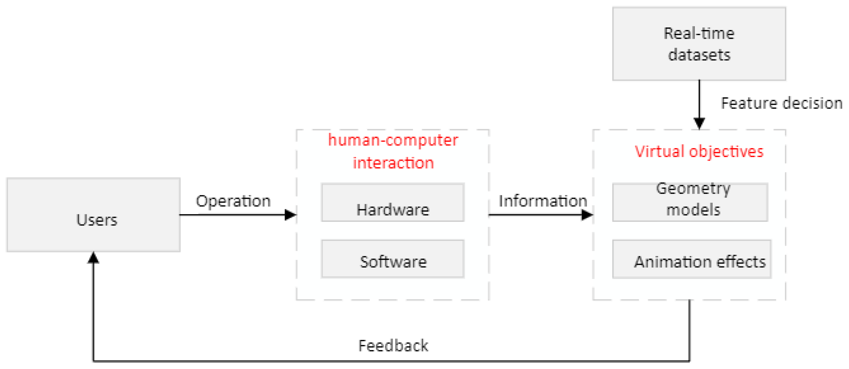
The ironmaking system under consideration consists of real-time data, geometric models, animation effects, and human–computer interaction modules. The real-time data comes from the field database and is transmitted to the simulation system through the data communication module. The relationship between the parts is shown in Figure 1. Geometric model and animation effects together constitute virtual objects in the simulation system. Some characteristics of virtual objects depend on real-time data changes. Virtual object animation effects are classified as motion effects and rendering effects. Script animation and particle animation are used to create motion effects, while shader technology is used to create rendering effects. Hardware and software make up the human–computer interaction module. When the user operates, the hardware module of human–computer interaction produces signals, and the software module of human–computer interaction collects the user’s operation information, which is transformed and communicated to the PC’s virtual reality simulation system. Virtual objects in the simulation system make corresponding feedback according to the user’s operation, and the user decides the next operation according to the feedback information of the simulation system.
3.2. The Shader Framework
The rendering pipeline is often separated into three phases: application, geometry, and rasterization [28]. Each level can be broken further into smaller pipeline phases.
The vertex shader is the first programmable shader in the rendering pipeline. The main task of the vertex shader is to transform vertex coordinates. By adding time parameters in vertex coordinate transformation, the function of vertex animation can be realized, so as to achieve a dynamic rendering effect. Vertex shaders also perform vertex-by-vertex lighting calculations.
Fragment shaders are another very important programmable shader in the rendering pipeline. The chip shader performs texture sampling, illumination model calculation, and so on. The chip shader outputs one or more color values or other chip metadata.
Geometry shader is an optional programmable shader that sits between the vertex shader and the fragment shader in the rendering pipeline. Geometric shaders operate on primitives. The geometry shader receives one or a group of vertices from the vertex shader and can then transform them, either by outputting new and different types of primitives or by increasing the number of vertices. This property can be used to achieve the effect of the particle system geometry shader.
4. The System Design
In this section, the Unity shader written by the ShaderLab language is used to illustrate the role of shader technology in the virtual reality simulation of the experimental system for blast furnace ironmaking by taking the rendering method of the iron pool and material layer as an example.
4.1. Iron Pool Special Effect Implementation Method
According to the morphological characteristics of molten iron, this work adopts the lava rendering method with a similar effect to render the iron pool. Based on the above analysis, the morphology characteristics of the iron pool are as follows: there is dynamic fluid movement in the iron pool, in addition, there are also small eddy currents randomly distributed on the surface of the molten iron. The color of molten iron is affected by temperature, and its color is mainly produced by the spontaneous luminescence of molten iron itself at high temperatures.
Data preparation is needed before we can start designing shaders for iron Pool rendering. In the vertex shader program, define a structure of type AppData to contain vertex coordinates in world space, normal vectors in world space, and texture coordinates (including main texture coordinates and noise texture coordinates). This structure is sent into the vertex shader.
The vertex shader transforms vertex coordinates using Unity’s built-in matrix variables and matrix transformation functions. In order to achieve the effect of molten iron flow, the texture coordinates are offset and transformed in the X-axis and Y-axis directions of world space with time as the independent variable:
where is the texture coordinates before transformation, is the texture coordinates after transformation, is the scaling coefficient, is the offset coefficient, is the movement speed of the texture coordinates in the X-axis and Y-axis directions, and t is the elapsed time since the current scene started running, respectively. There is no need to scale the coordinates in the iron pool effect realization procedure, merely offset, as seen above. is equal to (1,1). In addition to texture coordinate transformation, the following work needs to be completed: converting normal vectors in local space to world space; converting vertex coordinates in local space to world space. Both of these tasks can be achieved with Unity’s built-in matrices or functions.
Blinn–phong illumination model is used to calculate illumination in the chip shader [41,42,43]. Blinn–phong illumination model is divided into four parts: (1) self-illumination part, ; (2) specular reflection part, ; (3) diffuse reflection, ; (4) environmental light . The part of spontaneous light is taken from the color of spontaneous light of material, and the part of ambient light is taken from the color of global ambient light under the scene, which is generally sunlight. The calculation of specular reflection is as follows:
In Formula (1), is the light source color, is the highlight reflection color of the material, is the angle of view direction, and is the glossiness of the material (also known as the reflectance). The normalized calculation can be obtained by adding the angle of view direction and the light source direction variables of , and , respectively.
The diffuse reflection part is calculated as follows:
In Formula (3), is the diffuse color of the material and is the surface normal. After completing the illumination calculation of the four parts, overlay the above equation; then, we can rewrite it as:
The hash function is then used to generate random variables, which are used to obtain the random values or random vectors required in the process of noise generation. These random values and random vectors are used to construct the following two types of noise: Perlin noise and value noise. If there is only one noise, the two-dimensional random distribution sequence will be somewhat monotonous. One solution is to superimpose multiple noises. By stacking the noise in a loop (one octave at a time) and continuously increasing the frequency by some lacunarity, while reducing the amplitude of the noise by some proportion (gain), the final result is more detailed. The technique is called fractal Brownian motion, or fBM, or fractal noise. The technique is widely used to construct programmed landscapes [44,45,46,47,48]. After the Perlin noise and value noise are constructed, the two kinds of noise with different frequencies and different gains are superimposed according to the Brownian motion model, and the irregular temperature distribution in the molten iron is simulated.
As we work our way up octave after octave, the curves look more and more detailed, and the self-similarity becomes more and more obvious. If you zoom in on the curve, part of the curve looks very similar to the whole, and you can pick two different parts of the curve that look somewhat similar. This is an important property of mathematical fractals, which we simulated in the loop above. The presented framework is not trying to create a real fractal, because it cannot stack up after a couple of cycles, but in theory, if the presented method keeps going through the cycle, adding noise up and up, a more real mathematical fractal will be achieved. In computer graphics, there is always a limit to how much detail we can handle, such as when an object is smaller than a pixel, so there is no need to keep superimposing it to create fractal shapes. Sometimes we do need to stack many times, but not indefinitely. In Perlin noise and value noise, the following equation of relaxation curve is used to calculate the weight:
where t is the two-dimensional coordinate input on the planar grid for noise generation.
The random temperature distribution obtained by typing Brownian motion cannot be used directly. In order to form a mapping relationship between temperature distribution and color distribution, the iron pool can be approximately regarded as a black body, and the conversion from temperature value to RGB color value can be realized according to the relationship between color and temperature in the black body trajectory. First, the temperature is converted to uniform chromaticity coordinates, chromaticity coordinates, and tristimulus values successively, and finally, the tristimulus values are converted to RGB color values. In the bold body trajectory, the relationship between temperature and color value is as follows:
where u and V are uniform chromaticity coordinates, t is the temperature value (unit: K).
CIE 1931 XYZ color space is one of the first color spaces to be defined mathematically. It was established by the International Commission on Lighting (CIE) in 1931.CIE 1931 color spaces typically give trichromatic stimulus values for colors, expressed in terms of X, Y, and Z. In CIE 1931 color space, color chromaticity only depends on the ratio of X, Y, and Z, so the relative coefficients (also called chromaticity coordinates) X, Y, and Z chromaticity coordinates XYZ and uniform chromaticity UV coordinates have the following relationship:
The tri-stimulus values of the ci-RGB spectrum were obtained by a specialized color mixing and matching experiment with 317 normal visual subjects using the red, green, and blue primary colors and equivalent energy spectral colors from 380 nm to 780 nm specified by CIE. In the experiment, the number of red, green, and blue primary colors corresponding to the equal energy spectral color of for each wavelength of the spectrum is called the spectral three stimulus value. The relative luminance curve of isometric spectral colors is the same as that of bright vision spectral photo efficiency of human eyes. The conversion relationship between tristimulus value XYZ and chromaticity coordinate XYZ is as follows:
The specific conversion relationship between RGB color space and tristimulus values is as follows:
The rendered iron pool effect is shown in Figure 2a. Through vertex animation in the vertex shader, dynamic fluid movement in the iron pool is realized. Through the superposition of Perlin noise and value noise by Brownian motion, the fine eddy current and temperature state of random distribution on a hot metal surface are generated.
Special Effect Realization Method of Material Layer
After the above analysis, the morphological characteristics of the material layer are as follows: with the feeding process, the material surface will be on the rise. In addition, the surface of the layer model should be rough and uneven.
The first priority in our proposed digital twin shader system is to prepare an abundant furnace dataset [49,50,51,52,53,54]. To illuminate the solid backlit surface of the material layer, we add several additional light sources to the Unity scene, setting the intensity, radius, and position of the light source relative to the solid layer. The intensity, radius, and position of the light source are set on the basis that the side of the solid model of the entire material layer can be evenly illuminated, and the brightness is moderate, not too dark to look down on the solid side model details of the material layer, nor too bright to be too dazzling during operation. Since several additional light sources have been added to the Unity scene, the pass with the original render path forward base can only calculate parallel lights in the scene. Therefore, additional passes should be added to the Unity shader program to calculate additional light sources. In this special effect realization method, the type of light source we choose is a point light source. The range of illumination of a point source is limited. A three-dimensional sphere in world space defines a point light source. A point light source represents light emitted from a spot in all directions. After you have added a few point lights to the scene, you need to add another pass to the shader with the render path set to forward add. The presented framework adds the following statement to the code: #pragma multi-compile-fwd base. This directive ensures that light variables such as light attenuation are assigned correctly in the 3D shader. This directive is indispensable when adding a pass with a render path of ForwardAdd. In addition, to mix the colors of the two passes, you need to turn on the add blend mode and set the blend factor. The formula for additive mixing is as follows:
where O is the output color after blending, S is the source color, D is the target color (colors already in the color cache), and are the blending factor of the source and target colors, and are the blending factors of the alpha channel of the source and target colors. , are added with Blend One-One to pass with the render path ForwardAdd is given as follows:
That is, the result of the output color is the addition of the source color and the destination color already stored in the color cache.
The rising material layer can cause an effect on the vertex shader implementation idea. The dynamic fluid movements on the surface of the molten iron effect are also similar, but the material layer position changes usually only in one direction, so the y direction in world space, with time as the independent variable, to offset texture coordinates transformation , , namely in the implementation of the material layer of special effects, and type (1).
In the chip shader, we only need to calculate the illumination model. In addition, in order to simulate the effect of the uneven material layer, we need to add normal texture and carry out the corresponding calculation. Since the component range of normal is [−1, 1], while the component range of pixel value is [0, 1], transformation is required, usually using the following mapping:
which requires that after the normal texture is sampled in the slice shader, the sampling result should be reflected once to obtain the original normal direction:
In practice, the obtained normal texture stores normal data in the model space. To facilitate subsequent illumination calculation, normal data under tangent space is often used. Compared with the normal data in the local space, the calculation of the normal data in the tangent space requires several steps of coordinate transformation, and the obtained normal data are not as intuitive as the normal data in the local space. At the seams and sharp corners of the texture, the edges are rough and there are visible mutations or gaps; however, using normal data in tangent space at the same time has the following advantages:
- 1.
- The presented method builds the 3D ironmaking model with a high degree of freedom. In the local space, the normal map records absolute normal information, which means that the normal information obtained in the local space can only be used for a single model, and if this information is applied to other models, it may obtain the wrong bump effect. Normal texture in tangent space preserves relative normal data, which implies that even if the normal texture information is applied to a completely different model grid, a good result is then produced.
- 2.
- The presented digital twin framework achieves a superior UV animation effect. When we obtain the normal texture information in tangent space, we can move the UV coordinates of a texture to achieve a bump shift effect; however, if the normal texture information is obtained from the local space, it will obtain the completely wrong effect of movement. The reason for this difference is the same as above.
- 3.
- The proposed method can be reused for normal textures. For a hexahedron or more polyhedral, the presented digital system only needs one normal texture instead of six to obtain the desired bump effect. The principle of reuse is the same as above.
- 4.
- The complexity can be compressed. In local space, it is possible for a normal texture to store normal information in every direction, so a normal texture in local space must store normal component values in three directions and be in-compressible. In tangent space, the normal z component of a normal texture is always greater than 0 (positive direction), so when using a normal texture in tangent space, only the direction can be stored, and the Z direction can be derived from the direction.
Because of the benefits listed above, we frequently employ normal data recorded via normal texture in tangent space. Figure 2b depicts the material surface effect after rendering.
5. Specification of Implementation
5.1. Particle System Special Effect Implementation Method
In the proposed framework, the geometry shader is used to implement the particle dynamic system deployment. The geometry shader is positioned in the rendering pipeline after the vertex shader and before the fragment Shader. Geometric shaders, introduced in DirectX 10, take all vertices in the same region as input, generating new vertices, or regions. In addition, the data stream output copies the vertex information output by the geometric shader into four consecutive subsets of the output buffer; therefore, a geometry shader is a novel technology that is specially designed to deal with geometry in 3D scenes. Vertex shaders can append additional information to input primitives. At the same time, geometry shaders can also be used to access the information of adjacent vertices of primitives. In the days before geometric shaders were introduced, vertex shaders could only process information for a single vertex at a time, and output results for only one vertex at a time. If it is placed in the scene of the entire simulation system, then the amount of work to draw the geometry will be very large, and it will be very inefficient to rely only on the vertex shader to complete this work.
The geometry shader may batch-process geometry based on the vertex data generated by the previous stage’s vertex shader and perform data processing and geometry processing on the information next to the vertex to swiftly build new polygons. Through data streams, the results of geometry shaders are passed to other shaders or caches, freeing the CPU from complex and bulky geometry operations. Explosions, particle effects, waterfalls, and other complex and related scenes can all be rendered realistically with geometric shaders. The realization method of particle system special effects lies in the design of geometric shaders; however, Unity has now integrated the particle system, and Unity is now a full-fledged functional module that can be modified directly to achieve various effects. Unity’s particle system module is described in detail in Figure 2.
5.2. Shader Optimization Method
The number of CPU draw calls is one of the performance bottlenecks for shaders. The draw call numbers are directly reflected by the numbers of batches and SetPass calls. Batching is a common optimization technique, which is mainly used to reduce the number of draw calls. Batch processing is divided into dynamic batch processing and static batch processing. The basic idea behind dynamic batching is to mix the batchable grids for each frame, send the combined model data to the GPU, and render with the same material. The goal behind static batching is to combine the models that require static batching into a new grid structure only at the beginning of the run. Considering the convenience of operation, the optimization method of this system is static batch processing. Our proposed method is rendering based on high-performance GPU, in the experiments, we choose two RTX 3090 devices to model our scenarios and make the computation. We divide the industrial image into multiple batch sizes, after we obtain the result, we can output our results to the platform, which can be performed in a real-time interactive way. In contrast, the high computation load is allocated to the back workstation, so the whole computation process is a ‘statistic’ process, which finishes the optimization process and back to the global rendering coefficient. To implement static batch processing, simply check the static check box in the Unity 3D Geometry panel.
As for the dynamic simulation implementation, a real-time cloud database is connected to the experimental platform so that all the practical operation variables are transferred to the digital twin system in an online interactive way. Then, the digital twin system preprocesses these collected data resources in a static batch way, which means all the rendering process and shading is implemented in the GPU-based server, and the whole process can be finished in a static way. The rendering result can be fed back to the monitoring and then give the intuitive expression for the whole process; the specific evaluation and performance of this algorithm are based on the rending performance and GPU running time, which has been given in Table 1 and Figure 3 and Figure 4.
In addition to shader design, the system also involves the design of a geometric model, and the design of motion effects, which are introduced to these three parts of the design. The geometric model and motion effect design are given in the following stages.
Geometric model design: The geometric model is the most basic physical component of the virtual reality simulation system, and it is an important bridge connecting the blast furnace ironmaking system and the virtual reality simulation system. Considering the complete reconstruction of ironmaking equipment, the need for rapid modification, and the file format used by the development engine, this paper adopts a model design method based on geometric modeling and uses 3D Studio Max modeling software.
The process of geometric model design is as follows: (1) decompose the model according to the appearance information of the model; (2) choose the best modeling method for different parts of the model; (3) material production, rendering test, and model optimization; (4) import the Unity 3D platform and debug the model on the Unity 3D platform.
The steps of bf geometric model design include white model construction, material mapping, model rendering test, and import test.
Sports special effects: On the basis of geometric model design, it is necessary to add dynamic effects in the scene, that is, motion effects design. Motion effects design is divided into two parts: script animation and particle animation. This article’s scripted animation is a frame-by-frame transformation of certain attributes (such as position, size, and angle) of the objects in the scene (including camera, geometric model, text, etc.) by writing C# scripts.
Particle animation is implemented through Unity 3D’s own particle system. Unity 3D particle system has been a relatively mature tool module, commonly used functional modules include an emitter, particle change, collision, light and shadow effects, and rendering. Through the particle system, hot metal, flame, airflow, and other animation effects can be realized, as shown in Figure 3.
Virtual interaction digital twin approach: The virtual interaction method adopted in this color is HTC VIVE as a head-mounted display device, HTC VIVE’s matching laser locator as a positioning device, and HTC VIVE’s matching handle as a human–computer interaction device. In order to establish the connection between hardware devices and virtual content, VRTK is used as a software development tool.
VRTK toolkit contains two functional modules: scene roaming and gamepad interaction. VRTK provided the laser firing script VRTK_StraightPointerRenderer and the controller script VRTK_ControllerEvents. Using the above two scripts to modify the corresponding function events, the default parabolic roaming mode of VRTK is improved, that is, through the handle operation, it can be transmitted to any position in the three-dimensional space. The improved roaming mode is more suitable for observing the inside of the furnace, iron pool, and other objects. In order to realize the automatic roaming of scenes in a virtual reality simulation system, the camera control function is also designed.
6. System Simulation and Digital Twin Modeling
The operating environment of this system simulation system is as follows: CPU Intel Core I9-9980XE 3.00GHz, GPU NVIDIA GeForce RTX 2080 Ti, memory 32G.
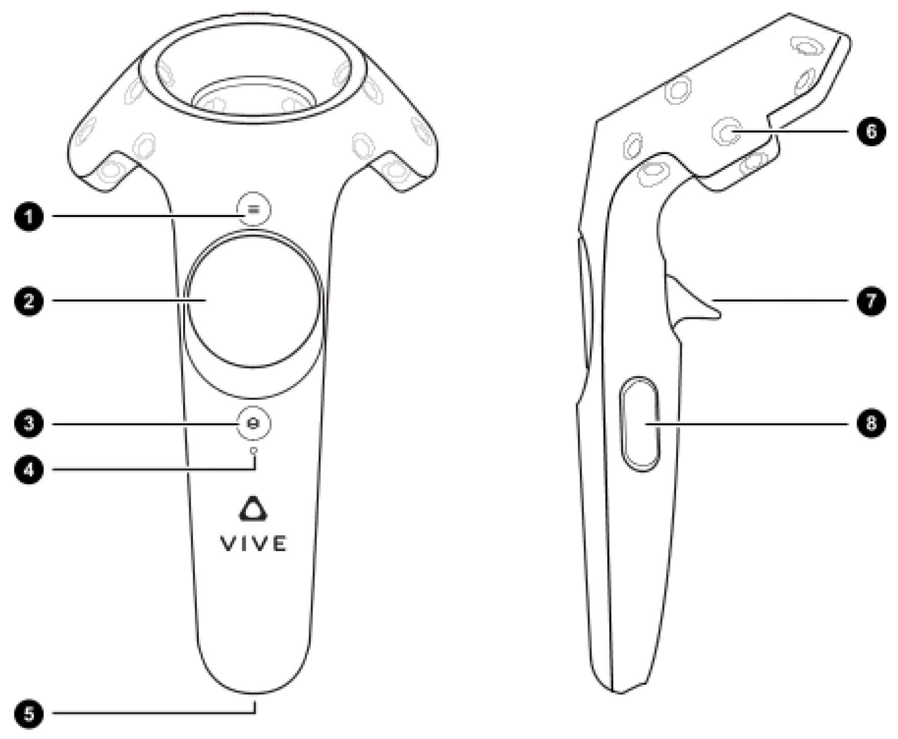
HTC VIVE control handling is shown in Figure 4. In the simulation process, the user mainly operates by the trigger on the handle. The presented method considers that the roaming mode is manual, the operator operates the trigger button on the handle to fire the linear laser, and the linear laser’s endpoint is the transmission point. Pressing the trigger button automatically increases the laser length, while the handle vibrates until the user believes the landing point is acceptable. Release the trigger button to teleport to the destination. So, when the virtual reality wandering scene moves to the charge’s surface, depth information of each location on the charge’s surface may be intuitively retrieved by drawing lines on the handle. The simulation of this function is shown in Figure 5. When the roaming status is automatic roaming, the handset interaction logic supports camera control and can realize functions such as pause, play, and prompt. The interface of the simulation system is shown in Figure 6.
In terms of system performance, the average operating frame rate before static batch processing is stable at about 15 FPS, and the number of batches is about 18,000. After a static batch operation, the average operating frame rate is about 75 FPS (the number of batches is about 3000) and may be over 100 FPS in some scenarios. Figure 7 and Table 1 illustrate a comparison of rendering statistics, CPU consumption, GPU usage, and memory utilization of the simulation system before and after static batch processing at the same time. Figure 8 depicts a normalized comparison of render data. The presented framework implemented that the average frame rate has been improved by 60 FPS, high to 75 FPS after the static batch processing. Other advantages such as memory usage and CPU usage can also be illustrated in Table 1.
According to the comparison in Table 1 and Figure 8, the number of batches and SetPass calls before static batch processing is large, which reflects a large number of draw calls, resulting in a low average frame rate and high CPU usage. After static batch processing, the number of batches and SetPass calls decreases significantly, that is, the number of draw calls decreases, the average frame rate increases significantly, and the CPU usage drops sharply. However, the GPU usage and memory usage hardly change before and after static batch processing.
Table 2 gives the different system performance evaluations, the corresponding index includes the memory usage, robustness, and stability, which demonstrates that the iron blast furnace systems follow the simulation results very well. The real operation results are coordinated with the system simulation. The rendering time in real operation is 83 ms, which is higher than the simulation, which is caused by the time delay in the data transmission process. Both the algorithm is the digital twin system test and real operation are stable, and also feasible in the robustness consideration. The algorithm computation is based on the analysis of the shader process, the digital twin system is 37 ms, and the real-test is 44 ms, which is a satisfactory solution.
7. Concluding Remarks
7.1. Problem Still to Be Solved
Although the performance of the suggested platform is good, much more research is required. For example, the final shader rendering must still be optimized. On the one hand, the aesthetic effect still enhances the space; on the other hand, rendering performance may be improved.
In the iron pool effect, although there is a dynamic effect and a small eddy rotating effect on the surface of the molten iron, there is a problem: the lack of a dynamic three-dimensional impression. The solution is to add a normal map or other bump map calculation into the chip shader of iron pool special effect rendering by referring to the realization method of bump effect of material layer surface, and the UV coordinates of the normal map can be dynamically calculated. It is also possible to add a sinusoidal wave effect to the vertex shader in the Iron Pool effect rendering. Due to the massive number of customizable factors involved in the special effect, the human–computer interaction interface of the iron pool can be considered in the future, in addition to the enhancement of the visual effect of the iron pool. The design of the human–computer interaction interface can be realized by C# script.
When the layer surface rises in the layer effect, the rising surface is totally horizontal. The rising state is too perfect; in actuality, the material surface of the feeding process should be uneven, higher in the center and lower on both sides of the feeding state. Therefore, in the animation design of the rising vertex of the material surface, each vertex’s different rising speeds should be considered. In addition, in the design of concave and convex effect, this system uses the method of adding several point light sources around the solid model of the material layer to illuminate the whole solid model, but there are no multiple point light sources in the material layer area of the blast furnace, so the design method of multi-point light source does not conform to the actual situation. This problem is mainly caused by the calculation of a normal map. In fact, there are other ways to implement bump textures besides normal mappings, such as height mapping, etc. More concave–convex texture implementation methods should be considered to test and compare the layer solid model rendering.
In terms of shader optimization, the system only uses Unity’s own static batch optimization method. There are several more shader optimization approaches, such as dynamic batch processing, model LOD technology, shared material technology, occlusion removal technology, multi-level fading texture (MIPMAP) technology, texture compression technology, resolution scaling technology, and so on. In addition to employing existing shader optimization technology, we need to evaluate various system performance bottlenecks and rendering characteristics and research more appropriate rendering optimization technology.
7.2. Summary and Prospect
Using blast furnace ironmaking as an example, this article contributes to the iron and steel manufacturing business by proposing an advanced digital twin virtual reality technology. It also builds a novel intelligent virtual reality simulation system of blast furnace ironmaking based on the Unity 3D engine. The geometric model and animation effects constitute the physical basis and core part of the system. The human–computer interaction module, which uses the HTC VIVE hardware device and the VRTK tool library as the theme, connects people to the system. The virtual reality blast furnace ironmaking simulation system allows the real-time parameters in the ironmaking reaction process to be visualized, the ironmaking process to be truly and vividly displayed, and the site operation to be safely and reliably simulated, allowing for further observation and exploration of the internal reaction mechanism related to blast furnace ironmaking. Thus, in blast furnace ironmaking this process promotes the progress of the iron and steel smart manufacturing production industry. Due to its effectiveness, this approach can be further researched and help more enterprises to improve working efficiency and reduce the production and energy costs. The study findings may be pushed and applied to other sections of the iron and steel production industry, as well as other associated metallurgy, chemical industry, manufacturing and other industries, in addition to simulating the blast furnace ironmaking process.
Author Contributions
Conceptualization Y.L., Methodology Y.L. and H.R.K., Software Y.L., Writing—Original draft preparation Y.L. and H.R.K., Investigation Y.L. and H.R.K., Data curation Y.L., Formal analysis Y.L. and H.R.K., Funding acquisition H.R.K., Supervision H.R.K., Visualization Y.L., Resources Y.L. and H.R.K. All authors have read and agreed to the published version of the manuscript.
Funding
This research received no external funding.
Informed Consent Statement
Not applicable.
Data Availability Statement
No new data were created or analyzed in this study. Data sharing is not applicable to this article.
Acknowledgments
This paper is supported by the Council Scholarship of China (CSC) under grant No. 202006370101. The authors would thank Nannan Long for the helpful discussion and suggestions on improving the quality of this paper.
Conflicts of Interest
The authors declare no conflict of interest.
References
- Jiang, K.; Jiang, Z.; Xie, Y.; Pan, D.; Gui, W. Abnormality Monitoring in the Blast Furnace Ironmaking Process Based on Stacked Dynamic Target-Driven Denoising Autoencoders. IEEE Trans. Ind. Inform. 2021, 18, 1854–1863. [Google Scholar] [CrossRef]
- Liu, X.; Chen, L.; Feng, H.; Qin, X.; Sun, F. Constructal design of a blast furnace iron-making process based on multi-objective optimization. Energy 2016, 109, 137–151. [Google Scholar] [CrossRef]
- Tyamo, O.; Armin, K.S.; Zhou, C.Q. Review on Computational Modeling and Visualization of the Ironmaking Blast Furnace study on Northwest of Purdue University. Steel Res. Int. 2019, 90, 1900046. [Google Scholar]
- Wang, H.; Chu, M.; Guo, T.; Zhao, W.; Feng, C.; Liu, Z.; Tang, J. Mathematical Simulation on Blast Furnace Operation of Coke Oven Gas Injection in Combination with Top Gas Recycling. Steel Res. Int. 2016, 87, 539–549. [Google Scholar] [CrossRef]
- Gao, Y.; Wang, Y.; Yang, J.; Zhang, X.; He, M. Meso-and macroeffects of roof split blasting on the stability of gateroad surroundings in an innovative nonpillar mining method. Tunn. Undergr. Space Technol. 2019, 90, 99–118. [Google Scholar] [CrossRef]
- Smallman, R.E.; Bishop, R.J. Modern Physical Metallurgy; Elsevier: London, UK, 2016; pp. 430–444. [Google Scholar]
- Lei, Y.; Chen, X.; Min, M.; Xie, Y. A semi-supervised Laplacian extreme learning machine and feature fusion with CNN for industrial superheat identification. Neurocomputing 2020, 381, 186–195. [Google Scholar] [CrossRef]
- Chenn, Z.; Guangwu, T.; Jichao, W.; Dong, F.; Tyamo, O.; Armin, S. Comprehensive Numerical Modeling of Blast Ironmaking Process. JOM 2016, 68, 1353–1362. [Google Scholar]
- Ma, K.; Deng, J.; Wang, G.; Xu, J. Utilization and impacts of hydrogen in the ironmaking processes: A review from lab-scale basics to industrial practices. Int. J. Hydrogen Energy 2021, 46, 26646–26664. [Google Scholar] [CrossRef]
- Ashish, A.; Kothari, A.K.; Ramna, R.V.; Padmapal; Singh, M.K. A review on liquid level measurement techniques using mathematical models and field sensors in blast furnace. Metall. Res. Technol. 2019, 116, 307. [Google Scholar]
- Burdea, G.C.; Coiffet, P. Virtual Reality Technology; John Wiley & Sons: New York, NY, USA, 2003. [Google Scholar]
- Wu, M.; Yang, J.; Huang, F.; Hua, L.; Xiong, S. Bonding of Cast Iron-Aluminum In Bimetallic Castings by High Pressure Die Casting Process. Int. J. Adv. Manuf. Technol. 2021, 120, 537–549. [Google Scholar] [CrossRef]
- Xie, H.L.; Wang, Q.H.; Ni, J.L.; Li, L.R. A GPU-based prediction and simulation method of grinding surface topography for belt grinding process. Int. J. Adv. Manuf. Technol. 2020, 106, 5175–5186. [Google Scholar] [CrossRef]
- Uhlenbrock, L.; Jensch, C.; Tegtmeier, M.; Strube, J. Digital twin for extraction process design and operation. Processes 2020, 8, 866. [Google Scholar] [CrossRef]
- Liu, J.; Zhou, H.; Tian, G.; Liu, X.; Jing, X. Digital twin-based process reuse and evaluation approach for smart process planning. Int. J. Adv. Manuf. Technol. 2019, 100, 1619–1634. [Google Scholar] [CrossRef]
- Liu, Q.; Liu, M.; Wang, Z.; Yan, F.; Ma, Y.; Shen, W. A novel intelligent manufacturing mode with human-cyber-physical collaboration and fusion in the non-ferrous metal industry. Int. J. Adv. Manuf. Technol. 2021, 119, 549–569. [Google Scholar] [CrossRef]
- Zhou, H.; Yang, C.; Sun, Y. A Collaborative Optimization Strategy for Energy Reduction in Ironmaking Digital Twin. IEEE Access 2020, 8, 177570–177579. [Google Scholar] [CrossRef]
- Boschert, S.; Rosen, R. Digital twin—The simulation aspect. In Mechatronic Futures; Springer: Cham, Switzerland, 2016; pp. 59–74. [Google Scholar]
- Long, N.; Lei, Y.; Peng, L.; Xu, P.; Mao, P. A scoping review on monitoring mental health using smart wearable devices. Math. Biosci. Eng. 2022, 19, 7899–7919. [Google Scholar] [CrossRef]
- Zhang, D.; Gao, X. A digital twin dosing system for iron reverse flotation. J. Manuf. Syst. 2022, 63, 238–249. [Google Scholar] [CrossRef]
- Lei, Y.; Karimi, H.R.; Cen, L.; Chen, X.; Xie, Y. Processes soft modeling based on stacked autoencoders and wavelet extreme learning machine for aluminum plant-wide application. Control. Eng. Pract. 2021, 108, 104706. [Google Scholar] [CrossRef]
- Lei, Y.; Chen, X.; Xie, Y. An improved cell situation identification approach with convolutional neural network and wavelet extreme learning machine. Proc. Inst. Mech. Eng. Part I J. Syst. Control. Eng. 2021, 235, 1898–1905. [Google Scholar] [CrossRef]
- Lei, Y.; Karimi, H.R.; Chen, X. A novel self-supervised deep LSTM network for industrial temperature prediction in aluminum processes application. Neurocomputing 2022, 502, 177–185. [Google Scholar] [CrossRef]
- Zenner, A.; Makhsadov, A.; Klingner, S.; Liebemann, D.; Kruger, A. Immersive Process Model Exploration in Virtual Reality. IEEE Trans. Vis. Comput. Graph. 2020, 26, 2104–2114. [Google Scholar] [CrossRef] [PubMed]
- Ahmed, S.; Hossain, M.M.; Hoque, M.I. A brief discussion on augmented reality and virtual reality in construction industry. J. Syst. Manag. Sci. 2017, 7, 1–33. [Google Scholar]
- Kao, D.; Mousas, C.; Magana, A.J.; Harrell, D.F.; Ratan, R.; Melcer, E.F.; Sherrick, B.; Parsons, P.; Gusev, D.A. Hack. VR: A Programming Game in Virtual Reality. arXiv 2020, arXiv:2007.04495. [Google Scholar]
- Lu, Y.; Liu, C.; Wang, K.I.-K.; Huang, H.; Xu, X. Digital Twin-driven smart manufacturing: Connotation, reference model, applications and research issues. Robot. Comput. Integr. Manuf. 2020, 61, 101837. [Google Scholar] [CrossRef]
- Lee, S.H.; Jung, B.S. Development of electric vehicle maintenance education ability using digital twin technology and VR. Int. J. Adv. Cult. Technol. 2020, 8, 58–67. [Google Scholar]
- Liu, S.; Lu, S.; Li, J.; Sun, X.; Lu, Y.; Bao, J. Machining process-oriented monitoring method based on digital twin via augmented reality. Int. J. Adv. Manuf. Technol. 2021, 113, 3491–3508. [Google Scholar] [CrossRef]
- Jain, P.; Poon, J.; Singh, J.P.; Spanos, C.; Sanders, S.R.; Panda, S.K. A digital twin approach for fault diagnosis in distributed photovoltaic systems. IEEE Trans. Power Electron. 2019, 35, 940–956. [Google Scholar] [CrossRef]
- Akimov, L.; Lvov, V.; Martino di Montegiordano, D.; de Mei, K.; Osipov, N.; Ostrovaia, A.; Krasnozhen, S.; Badenko, V.; Terleev, V. Shading System Design and Solar Gains Control for Buildings Passive Energy-Efficiency Improvement. In Technological Advancements in Construction; Spring: Cham, Switzerland, 2022; pp. 13–24. [Google Scholar]
- Lyons, N. Deep Learning-based Computer Vision Algorithms, Immersive Analytics and Simulation Software, and Virtual Reality Modeling Tools in Digital Twin-driven Smart Manufacturing. Econ. Manag. Financ. Mark. 2022, 17, 67–81. [Google Scholar]
- Lattanzi, L.; Raffaeli, R.; Peruzzini, M.; Pellicciari, M. Digital twin for smart manufacturing: A review of concepts towards a practical industrial implementation. Int. J. Comput. Integr. Manuf. 2021, 34, 567–597. [Google Scholar] [CrossRef]
- Aydemir, H.; Zengin, U.; Durak, U.; Hartmann, S. Designing a virtual iron bird as a digital twin. In Proceedings of the AIAA Scitech 2021 Forum, virtual event, 11–15 & 19–21 January 2021; p. 0239. [Google Scholar] [CrossRef]
- Zhou, H.; Yang, C.; Sun, Y. Intelligent Ironmaking Optimization Service on a Cloud Computing Platform by Digital Twin. Engineering 2021, 7, 1274–1281. [Google Scholar] [CrossRef]
- Feldt, J.; Kourouklis, T.; Kontny, H.; Wagenitz, A. Digital twin: Revealing potentials of real-time autonomous decisions at a manufacturing company. Proc. CIRP 2020, 88, 185–190. [Google Scholar] [CrossRef]
- Huang, S.; Wang, G.; Lei, D.; Yan, Y. Toward digital validation for rapid product development based on digital twin: A framework. Int. J. Adv. Manuf. Technol. 2022, 119, 2509–2523. [Google Scholar] [CrossRef]
- He, B.; Bai, K.J. Digital twin-based sustainable intelligent manufacturing: A review. Adv. Manuf. 2021, 9, 1–21. [Google Scholar] [CrossRef]
- López, C.E.B. Real-time event-based platform for the development of digital twin applications. Int. J. Adv. Manuf. Technol. 2021, 116, 835–845. [Google Scholar] [CrossRef]
- Qi, Q.; Tao, F.; Zuo, Y.; Zhao, D. Digital twin service towards smart manufacturing. Procedia Cirp 2018, 72, 237–242. [Google Scholar] [CrossRef]
- Qi, Q.; Tao, F. Digital twin and big data towards smart manufacturing and industry 4.0: 360 degree comparison. IEEE Access 2018, 6, 3585–3593. [Google Scholar] [CrossRef]
- Boje, C.; Guerriero, A.; Kubicki, S.; Rezgui, Y. Towards a semantic Construction Digital Twin: Directions for future research. Autom. Constr. 2020, 114, 103179. [Google Scholar] [CrossRef]
- Regan, M.; Pose, R. Priority rendering with a virtual reality address recalculation pipeline. In Proceedings of the 21st Annual Conference on Computer Graphics and Interactive Techniques, New York, NY, USA, 24–29 July 1994; pp. 155–162. [Google Scholar]
- Guo, H.; Zhu, Y.; Zhang, Y.; Ren, Y.; Chen, M.; Zhang, R. A digital twin-based layout optimization method for discrete manufacturing workshop. Int. J. Adv. Manuf. Technol. 2021, 112, 1307–1318. [Google Scholar] [CrossRef]
- Negri, E.; Berardi, S.; Fumagalli, L.; Macchi, M. MES-integrated digital twin frameworks. J. Manuf. Syst. 2020, 56, 58–71. [Google Scholar] [CrossRef]
- Schaefer, J.L.; Baierle, I.C.; Sellitto, M.A.; Siluk, J.; Furtado, J.C.; Nara, E. Competitiveness scale as a basis for Brazilian Small and Medium-Sized Enterprises. Eng. Manag. J. 2021, 33, 255–271. [Google Scholar] [CrossRef]
- Zhou, G.; Zhang, C.; Li, Z.; Ding, K.; Wang, C. Knowledge-driven digital twin manufacturing cell towards intelligent manufacturing. Int. J. Prod. Res. 2020, 58, 1034–1051. [Google Scholar] [CrossRef]
- Shao, G.; Helu, M. Framework for a digital twin in manufacturing: Scope and requirements. Manuf. Lett. 2020, 24, 105–107. [Google Scholar] [CrossRef]
- Liu, X.; Deng, Y.; Han, C.; Di Renzo, M. Learning-based prediction, rendering and transmission for interactive virtual reality in RIS-assisted terahertz networks. IEEE J. Sel. Areas Commun. 2021, 40, 710–724. [Google Scholar] [CrossRef]
- Zörnack, G.; Weiss, J.; Schummers, G.; Eck, U.; Navab, N. Evaluating surface visualization methods in semi-transparent volume rendering in virtual reality. Comput. Methods Biomech. Biomed. Eng. Imaging Vis. 2021, 9, 339–348. [Google Scholar] [CrossRef]
- Liu, X.; Deng, Y. Learning-Based Prediction, Rendering and Association Optimization for MEC-Enabled Wireless Virtual Reality (VR) Networks. IEEE Trans. Wirel. Commun. 2021, 20, 6356–6370. [Google Scholar] [CrossRef]
- Wang, F.; Shiomi, H.; Ito, T.; Kakue, T.; Shimobaba, T. Fully analytic shading model with specular reflections for polygon-based hologram. Opt. Lasers Eng. 2023, 160, 107235. [Google Scholar] [CrossRef]
- Newlands, C.; Zauner, K.P. Procedural Generation and Rendering of Realistic, Navigable Forest Environments: An Open-Source Tool. arXiv 2022, arXiv:2208.01471. [Google Scholar]
- Li, B.; Furukawa, T. DRM-Based Colour Photometric Stereo Using Diffuse-Specular Separation for Non-Lambertian Surfaces. J. Imaging 2022, 8, 40. [Google Scholar] [CrossRef]
Figure 1.
System structure block diagram; the interaction of the dynamic rendering and shader process is given with this illustrative examples. The main procedure covers human–computer interaction and three-dimensional virtual objective modeling.
Figure 1.
System structure block diagram; the interaction of the dynamic rendering and shader process is given with this illustrative examples. The main procedure covers human–computer interaction and three-dimensional virtual objective modeling.

Figure 2.
Shaders render renderings of ironmaking blast furnace process. It is a three-dimensional rendering of the whole iron pool and the material layer with high-resolution textures. (a) The rending of the inner ironmaking pool; (b) Three-dimensional dynamic material layer rending effect.
Figure 2.
Shaders render renderings of ironmaking blast furnace process. It is a three-dimensional rendering of the whole iron pool and the material layer with high-resolution textures. (a) The rending of the inner ironmaking pool; (b) Three-dimensional dynamic material layer rending effect.

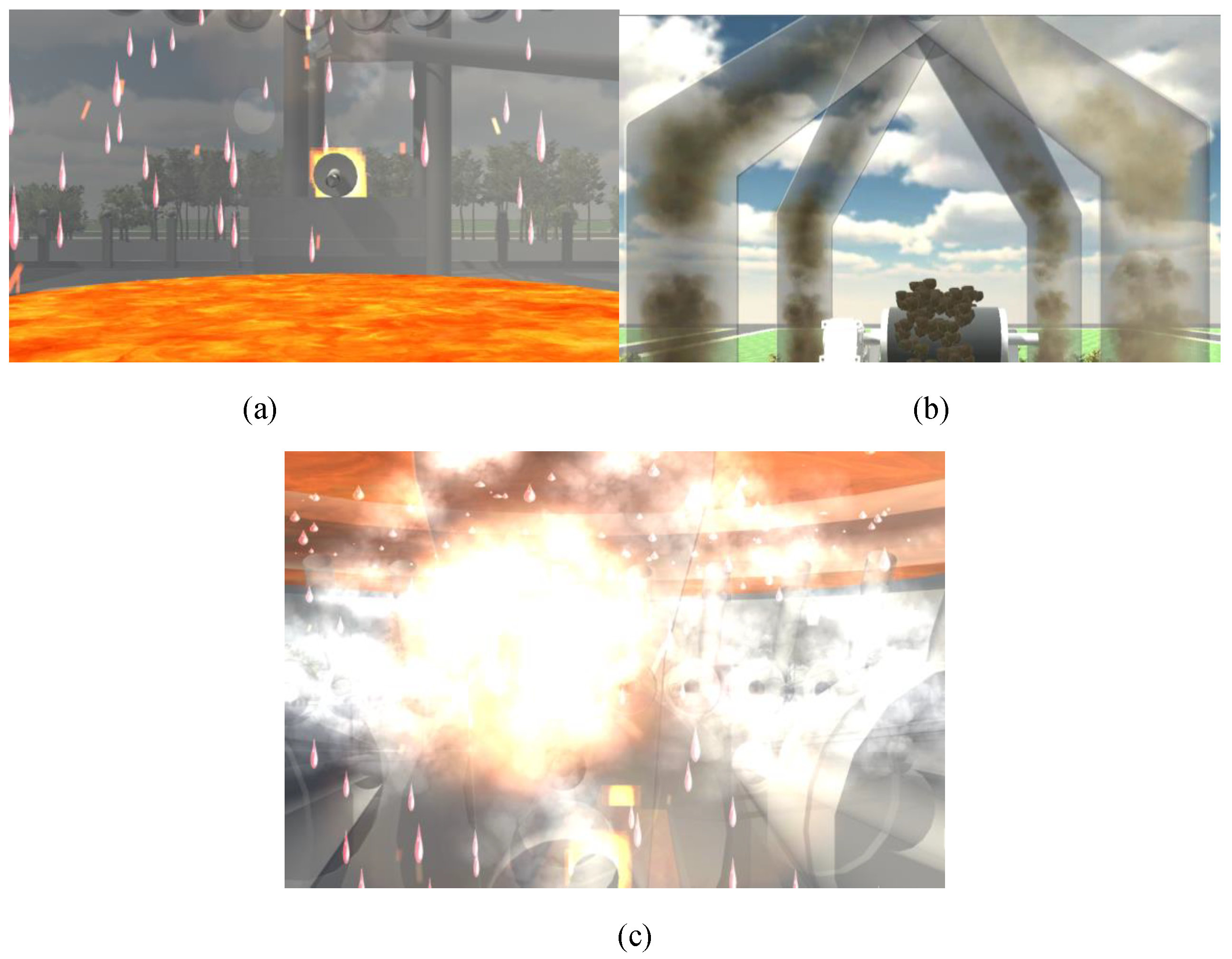
Figure 3.
Particle animation renderings of the ironmaking blast furnace process. (a) The whole dripping effect of the molten iron which is the main reaction; (b) Airflow renderings; (c) Flame renderings of ironmaking production plant.
Figure 3.
Particle animation renderings of the ironmaking blast furnace process. (a) The whole dripping effect of the molten iron which is the main reaction; (b) Airflow renderings; (c) Flame renderings of ironmaking production plant.

Figure 4.
Schematic of HTC VIVE controller. (1) Menu button; (2) Trackpad; (3) System button; (4) Status light; (5) MiroUSB port; (6) Tracking sensor; (7) Trigger; (8) Grip button.
Figure 4.
Schematic of HTC VIVE controller. (1) Menu button; (2) Trackpad; (3) System button; (4) Status light; (5) MiroUSB port; (6) Tracking sensor; (7) Trigger; (8) Grip button.

Figure 5.
The schematic diagram of material surface depth information acquisition for ironmaking process. The shaders for the highest point are set as accurately 1.542 m for the iron reaction process.
Figure 5.
The schematic diagram of material surface depth information acquisition for ironmaking process. The shaders for the highest point are set as accurately 1.542 m for the iron reaction process.

Figure 6.
3D virtual reality digital twin system interface of the iron blast. The main element of the large-scale blast furnace digital twin system has been tagged.
Figure 6.
3D virtual reality digital twin system interface of the iron blast. The main element of the large-scale blast furnace digital twin system has been tagged.

Figure 7.
Render statistics after static batch processing. (a) BSBP render statics; (b) ASAP render parameters.
Figure 7.
Render statistics after static batch processing. (a) BSBP render statics; (b) ASAP render parameters.

Figure 8.
Comparison of performance parameters before and after static batch processing after normalization. The blue histogram depicts before static batch processing, whereas the red histogram shows after processing.
Figure 8.
Comparison of performance parameters before and after static batch processing after normalization. The blue histogram depicts before static batch processing, whereas the red histogram shows after processing.


Table 1.
Comparison specification of performance parameters before and after static batch processing.
Table 1.
Comparison specification of performance parameters before and after static batch processing.
| Indexes | BSBP | ASBP |
|---|---|---|
| Average frame rate (FPS) | 15.0 | 75.0 |
| Batches | 18,000 | 3000 |
| SetPass Calls | 7500 | 2500 |
| CPU usage | 80% | 25% |
| GPU usage | 25% | 25% |
| Memory usage | 45% | 30% |
Table 2.
System evaluation performance comparisons.
| Performance | Real Operation | Digital Twin System |
|---|---|---|
| rendering time | 83 | 75.0 |
| Batches | 2590 | 3376 |
| response time | 30 ms | 25 ms |
| Stability | feasible | feasible |
| Robustness | feasible | feasible |
| GPU usage | 26% | 25% |
| Memory usage | 45% | 30% |
| computation time | 44 ms | 37 ms |
Publisher’s Note: MDPI stays neutral with regard to jurisdictional claims in published maps and institutional affiliations. |
© 2022 by the authors. Licensee MDPI, Basel, Switzerland. This article is an open access article distributed under the terms and conditions of the Creative Commons Attribution (CC BY) license (https://creativecommons.org/licenses/by/4.0/).
Share and Cite
MDPI and ACS Style
Lei, Y.; Karimi, H.R. A Digital Twin Model of Three-Dimensional Shading for Simulation of the Ironmaking Process. Machines 2022, 10, 1122. https://doi.org/10.3390/machines10121122
AMA Style
Lei Y, Karimi HR. A Digital Twin Model of Three-Dimensional Shading for Simulation of the Ironmaking Process. Machines. 2022; 10(12):1122. https://doi.org/10.3390/machines10121122
Chicago/Turabian StyleLei, Yongxiang, and Hamid Reza Karimi. 2022. "A Digital Twin Model of Three-Dimensional Shading for Simulation of the Ironmaking Process" Machines 10, no. 12: 1122. https://doi.org/10.3390/machines10121122
Note that from the first issue of 2016, this journal uses article numbers instead of page numbers. See further details here.