
A Review of End-Effector Research Based on Compliance Control

Key Laboratory of Advanced Manufacturing Intelligent Technology of Ministry of Education, School of Mechanical and Power Engineering, Harbin University of Science and Technology, Harbin 150080, China
*
Author to whom correspondence should be addressed.
Machines 2022, 10(2), 100; https://doi.org/10.3390/machines10020100
Submission received: 13 December 2021
/
Revised: 19 January 2022
/
Accepted: 24 January 2022
/
Published: 28 January 2022
(This article belongs to the Special Issue Robotization of Machining Processes: Theory and Industrial Applications)
Abstract
:The end-effector is a key device for direct contact and operation between the operator and the workpiece, and its mechanical structure will directly affect the quality of the machine and expand its application. The theoretical research and technical implementation of the end-effector for compliance control are facing a lot of urgent challenges to be solved, therefore, the research results of active compliance control of robot end-effectors have a very broad application prospect. This paper describes the design and research results of different end-effectors under impedance-based control, hybrid force/position control, and intelligent flexible control methods, respectively. Under each control method, the structural characteristics and the optimized control scheme under different drives are introduced. Finally, key techniques for achieving compliance control are derived by summarizing, which broadens the engineering applications and provides methods and ideas for future research.
1. Introduction
With the advancement of manufacturing intelligence, many occasions require machines with the ability to sense and control contact forces. For example, during the precision assembly, grinding, polishing, and scrubbing operations of robots, it is required to keep their actuators in contact with each other and the environment [1]. Single position control is often not enough to meet the demand. For more complex tasks, the uncertain working environment, changing assembly, and high-precision assembly operations require tolerances that exceed even the accuracy that the robot itself can achieve [2]. At this point, it is not only expensive but also potentially futile to still try to further improve accuracy through position control. The use of compliance control is one of the solutions to this type of problem.
There are two main types of this control: passive and active. The former adjusts the gain of the position control system by its own controller to change the overall stiffness of the arm to adapt to the stiffness of the external environment [3]. For example, Ramon et al. [4] designed a passive control system and proposed a sensor-less control method based on the accurate tracking error dynamic passive output feedback (ETEDPOF) method for the angular velocity trajectory tracking of the “full-bridge Buck inverter-DC motor” system. Aguilar et al. [5] proposed a Liapunov-based construction method for output feedback quenching of continuous regenerative DC-DC buck power converters and experimentally verified the anti-winding property and the efficiency of the “∑-∆“ modulator of this scheme.
The latter involves the design of a flexible mechanical device and requires such a device to enable the arm to absorb or store energy when it interacts with the environment [6]. What is commonly referred to as softness control is active softness control. As an important feature of intelligence, the study of flexibility control capability for end-effectors has become an important research direction.
An end-effector is a mechanism that is installed on a mobile device or a robotic arm, so that it can complete the functions of clamping, placing, and releasing the target object to an accurate position [7]. The actions of the end-effectors are coordinated with the robot to complete the job together, and most mechanisms are designed according to the requirements of specific workpieces [8]. The different characteristics of the object and the requirements of the different operating parameters influence the elements of the actuator, which include construction, gripping method, gripping force and drive, and so on [9,10]. In recent years, end-effectors have played an increasingly important role in scientific research and engineering applications, such as underwater surveys, military industry, welding assemblies, medical applications, etc. Some of the more popular research directions in the field of mechanisms are parallel mechanisms, unfolding mechanisms and series-parallel mechanisms [11,12]. With the continuous research and technological advancement in robot-related research, higher requirements for robot actuators have been put forward [13]. A comprehensive design of the actuation structure based on different functional requirements can greatly improve the adaptability of the robot gripping mechanism [14,15].
The design of the actuator structure varies depending on the variety of robot forms [16]. The actuating part is in direct contact with the workpiece, and its structural design is particularly important; the driving part mainly provides the driving force for the actuating part, so that the actuator can realize the corresponding gripping action [17,18,19]. The transmission system of the gripping mechanism is mainly in the form of mechanical transmission, hydraulic transmission, pneumatic and electric transmission, etc., [17,18,19,20,21,22,23,24,25]; the control system is to control the robot according to specific procedures and requirements so that the machine can complete the specified gripping action and tasks [22,23]; the auxiliary system contains various detection devices, sensing devices, identification devices, etc., [24,25]. Together, they serve the actuator to ensure the smooth implementation of the gripping work.
What is commonly referred to as softness control is the active softness control [26], which can be implemented in three ways. The first way is impedance control (including stiffness control and damping control) [27]; the second way is hybrid force/position control [28], and the last one is intelligent compliance control [29]. This paper focuses on the design of the end-effector structure and the optimized control scheme that can realize flexible control. It has been arranged as follows: Chapter 2 and 3 specifically introduce two end-effector classical flexible control methods. A distinction is made between the end-effectors under different drive methods, which include four methods: mechanical, pneumatic, electric, and electromagnetic. Under each control, we summarize the different structures, the working principle of the device, advantages, and disadvantages, etc. Chapter 4 gives a detailed introduction to the research of modern intelligent flexible control. In the fifth part, we summarize the end-effectors according to the previous introduction and come up with the key technologies to realize the compliance control of end-effectors. Finally, we summarize the whole paper and provide ideas and research directions for the future design of end-effectors based on compliance control.
2. Implementation of Impedance Control Actuators
2.1. Introduction to the Impedance Control
The impedance control is proposed by Hogan [30]. Rather than directly controlling the desired force and position, impedance control achieves a supple function by controlling the dynamic relationship between force and position. The end of the manipulator is made to exhibit the required stiffness and damping by an appropriate control method. Typically, the DOF requiring force control requires less rigidity in that direction and exhibits softer characteristics. For the DOF that require force control, less rigidity in that direction is required, which exhibits softer characteristics [31]. This dynamic relationship is similar to the concept of impedance in a circuit and is therefore called impedance control [32]. Its characteristic is that it does not directly control the force between the robot and the environment, but adjusts the feedback position error, velocity error, or stiffness to achieve the purpose of controlling the force according to the relationship between the position (or velocity) of the robot end and the force acting on the end. The elastic deformation of the contact process is particularly important at this point [33].
In the two types of impedance control, the inputs to the controller are position error and velocity error [34,35]. When the force feedback signal is converted into the position adjustment quantity, this force control is called stiffness control; when the force feedback signal is converted into the velocity correction quantity, this force control is called damping control; when the force feedback signal is converted to both position and velocity corrections, it is called impedance control. Thus, impedance control is fundamentally position control, whether it is stiffness control or damping control. Specifically, it is an expansion of the position control principle.
The core of the impedance control structure is the design of the force/motion conversion matrix “K”. The force/motion conversion expression is “”. From the force control point of view, it is hoped that the larger the elements in the “K” array, the better, so that the system will be more flexible; from the bit control point of view, it is hoped that the smaller the elements in the “K”, the better, so that the system is more rigid. Thus, it also reflects the contradiction of the requirement of robot rigidity and flexibility, which also brings great difficulties to the actuator force control [36,37].
To achieve impedance control, the first step is to characterize the force between the mechanical end and the environment, while in the whole impedance control system, the expected force of the end-effector is:
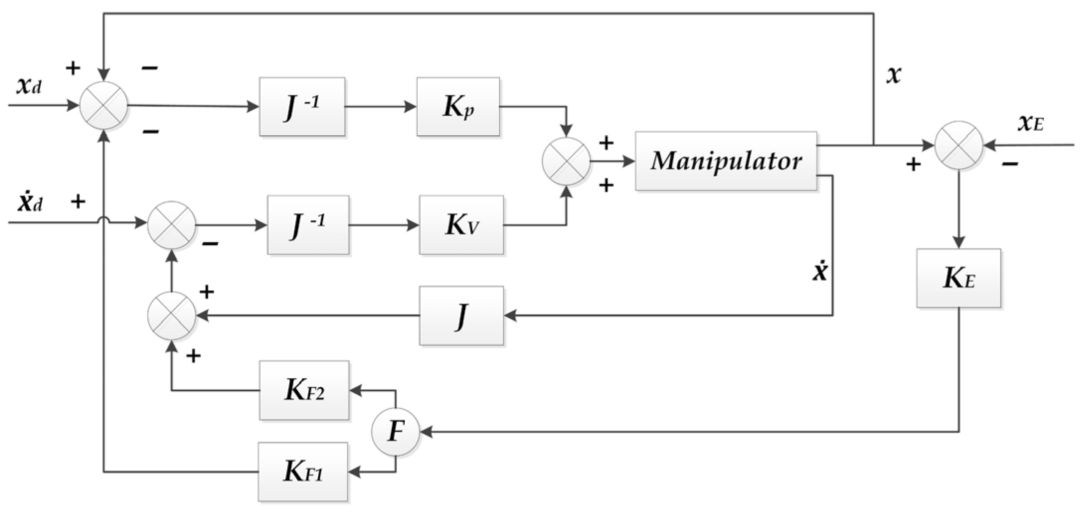
where “” is the end position error, “” is the desired position, and “” is the actual position. K, B, M are the stiffness, damping and inertia coefficient matrices, respectively, which are formed by the environment. Figure 1 shows one composition scheme of the resistance control system [35].
2.2. Review of Impedance Control Mechanisms’ Research
2.2.1. Mechanical
Mechanical impedance controllers can rely on the structure itself to achieve rigidity and flexibility, for example, by using gears, springs, or material properties for soft adjustment. Lee et al. [38] proposed a flexible end-operator. It mainly uses springs to achieve axial flexibility control and uses universal joints to achieve flexibility control of other degrees of freedom such as rotation, but the control accuracy is relatively low. The actuator invented by Xu [39] et al. controls the bending stiffness of each finger joint by varying the number of flexible lamellae and the thickness of the joint connection unit as well as the stiffness of the elastic steel lamellae. The structure is designed with a one-piece flexible structure for each finger and combined with 3D printing technology, it can be personalized for different hand sizes at a low cost. Yao et al. [40] invented a rigid and flexible switchable manipulator. The structure is equipped with an elastic polymer manipulator for directional bending, and its internal cavity can achieve expansion and compression. It combines the flexible manipulator and the phase change properties of liquid metal materials [41]. David et al. [42,43] invented a spring-based automatic actuator for multi-purpose medical instruments It can use the spring to control the mechanism to complete the grasping, shrinking, cutting, dissection or other surgical functions. Moreover, this mechanism can be combined independently with rigid or flexible endoscopes of any size.
In addition to the rigid-flexible conversion, the actuator position can also be controlled directly and precisely. Wang et al. [44,45] equated the end-effector for grasping fruits and vegetables to a second-order impedance first-order conductance model. The end-effector gripping force impedance control strategy is shown in Figure 2. The control algorithm is highly adaptable to the uncertainty and force perturbation of the object model, and can quickly control the gripping force with a low overshoot to achieve flexible robot grasping. The structural design and control system of the end-effector was studied by Cheng et al. [46] for a small underwater double-arm manipulator. It uses a pushrod telescoping and linkage self-locking mechanism to realize the opening and closing function of the gripper jaws. The control system adopts two-level control above and below water, and PID control is performed by smoothing the joint module with multiple interpolation so that the manipulator has better motion and basically realizes the function of the control system. Li et al. [47] proposed a method for precise position control of a soft robot based on a fuzzy time lag algorithm. As shown in Figure 3, the SMA wires of different materials are embedded in the structure of the soft robot, and the basic mechanism of the variable stiffness of this actuator relies on SMA filaments. Finally, they proved that the method is a feasible SMA actuator position control method.
2.2.2. Pneumatic
Pneumatic type can provide greater and more stable driving force compared with mechanical type, and the driving effect is better. Ryuh et al. [48] proposed a single-degree-of-freedom force-controlled end-effector using a cylinder for axially flexible control, and it can directly drive the tool head for rotational motion, reducing the mass of the tool head power components and improving the response speed and load capacity. Zhang [49] et al. invented a large-load flexible manipulator based on rigid constraints. The mechanism is provided with three flexible manipulator fingers, and each finger is connected to the driving device through an installed trachea. A strain limiting layer made of non-stretchable textile mesh is attached to the inner surface of the finger so that the deformation on one side of the finger is limited. Li et al. [50] proposed a large-load pneumatic flexible end-effector based on a fiber-reinforced flexible actuator. A new gripping body construction method with a single pneumatic artificial muscle winding layout is adopted in the structure. They add pre-deformation to the inner cavity of the soft body end to achieve its regular contraction to complete the gripping of objects with different characteristics. It provides new ideas and new methods for the development of soft body end.
The control can also be accomplished by compensating for the execution platform. Wang et al. [51] designed an end-stage for a parallel robot with three DOF. They used PID [52] and LADRC [53] algorithm to complete the trajectory control of the pneumatic parallel translating robot platform, respectively. Jeremy Krause et al. [54] developed a pneumatic actuator as shown in Figure 4. The actuator was demonstrated using setpoint control based on standard proportional and integral controllers with the parameters shown in the figure. In contrast, their actuator is linear and has a large travel distance. It usually operates at relatively high pressure. Thus, a great force and responsiveness can be provided, which is the main novelty of their work. The actuator addresses the placement of the position and force control sensor and successfully demonstrates the force and impedance control of the actuator. Their work has the potential to open up new avenues for creating cheaper, customizable and capable actuators for industrial and other applications.
Currently, soft end-effectors are one of the most promising research directions in the field of soft robotics [55]. With its strong ability to operate in unstructured environments and broad development prospects, the soft end has made a large impact, and its inherent potential will enable it to provide better services to humans in a more diversified way [56,57]. Lv et al. [58]. designed the pneumatic driven soft robot actuator from a bionic perspective. The bending deformation of this modular actuator is achieved by controlling the magnitude and timing of the pressure inside the actuator cavity. Finally, they demonstrated the feasibility of bending the actuator. Wehner et al. [59]. controlled the flow of air in and out of the actuator by tuning the impedance limits to produce bending actuation. The finger actuator configuration system is shown in Figure 5. This configuration is used for uncontrolled, passive impedance control and visual servo feedback control methods. For the uncontrolled and passive impedance control methods, the camera and PC are used for data acquisition only.
2.2.3. Motorized
Compared with the first two drive methods, the electric drive is more widely and conveniently used. Wang et al. [60] developed a new vibratory electric cutting tool for space maintenance tasks and chose a force-based impedance control to achieve the active supply control of the robotic arm. The direct force control achieves the force tracking and simultaneous control of force and motion in all task directions by the parallel control. To achieve accurate control of the robot, Xu et al. [61] introduced the three-dimensional information of the aspen in the BAS algorithm into the PID parameters, and in the iterative optimization process, the ITAE adaptation function, which measures the stability of the system, was reduced to solve the viscoelasticity problem existing in DEA. Mohammad et al. [62] developed a new small mass force-controlled end manipulator for robotic polishing. The rotary motor drives the polishing head through the spindle for rotational motion and the linear hollow voice coil motor for axial force control. As the mass of the moving parts is greatly reduced, not only the output capacity of the axial compensation device is reduced, but also the noise and vibration are reduced. Fernando et al. [63] designed a multi-degree-of-freedom active flexible end manipulator. It mainly consists of DC motors, roller screws upper and lower stages, etc. It can control the position of upper and lower stages by six DC motors to achieve multi-degree of freedom active flexure control.
2.2.4. Electromagnetic
The electromagnetic drive can provide a relatively large electromagnetic force, but its application range will also receive certain limitations. Wang et al. [64] invented a magnetic gripping device that can switch between rigid and flexible. It adjusts the degree of separation of the cone surface by controlling the cylinder piston rod, thus changing the rigid and flexible state of the magnetic gripper. This device avoids the problems of deformation, damage, and alarm caused by the reaction force when the workpiece is placed on the fixture.
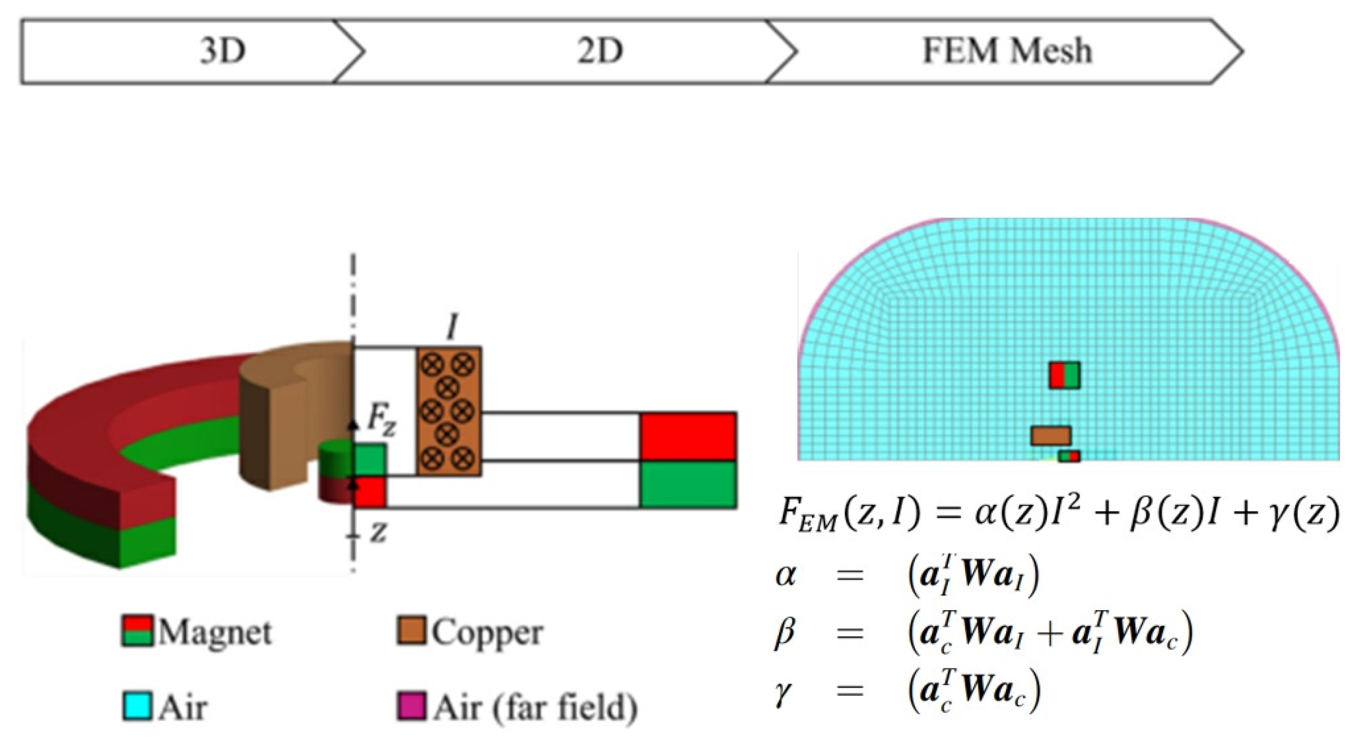
Liu et al. [65] modified the three-finger end-effector positional attitude based on the integrated virtual impedance control. They achieved a high-precision connection by analyzing the structure of the end-effector and the grappling hook interface, and mounted the corresponding grappling hook interface on the target for co-capture. They propose an “ivic”-based actuator attitude correction method to avoid collisions and reduce the unavoidable contact shock. Moreover, the rationality of the structure is verified by two sets of experiments. After that, Simon et al. [66] presented a complete controller design scheme for magnetic field orientation control (FOC) of brushless DC motors. The active impedance controller is mainly used for the compliant control of the trajectory of the robot end-effector. They propose a standard and well-known pole-based configuration method that involves only controlling the flexibility of the rotor axis. The design of the super magnetostrictive actuator and its magnetic circuit was carried out by Chen et al. [67]. The order of magnitude of the input voltage is effectively reduced, which improves the stability and power transfer of the system. Arwed et al. [68] developed a novel electromagnetic-free flight micro-actuator position control system stage model shown in Figure 6. They developed an innovative design of a free-moving actuator and designed a PD controller for reflector position feedback control. The one-dimensional equations of motion were obtained by combining the model’s electromagnetic force, gravity, air resistance, and inertia.
According to the above research results of end-effector based on impedance control, the innovative structural design results are shown in Table 1.
3. Implementation of Force/Position Control Actuators
3.1. Introduction to the Hybrid Force/Position Control
The basic idea of dynamic hybrid force/position control is to decompose the task into position control in some degrees of freedom and force control in some other DOF in the flexible coordinate space and to perform the calculation of position control and force control in the task space separately, and then to convert the calculation results to the joint space to merge them into a unified joint control torque to drive the manipulator to achieve the desired flexible function [69].
Mason first proposes the concept of simultaneous non-contradictory force and position control and the idea of joint suppleness in 1979 [70]. His approach is to control the force and position independently for different joints of the robots according to specific task requirements, which has some limitations. M.H. Raibert and J.J. Craig [71] conducted an important experiment in 1981 on hybrid position and force control of robotic manipulators. They assign forces and positions in any direction in the workspace to individual joint controllers utilizing Jacobi matrices and achieved good results. Later, this controller is called an “R-C” controller [72].
Figure 7 represents the structure of the “R-C” controller. In the “R-C” force/position hybrid controller, the torque of each drive motor is provided by two relatively independent control loops, the position loop (upper), and the force control loop (lower), respectively. The position loop gets the corresponding joint position and velocity from the desired end position and velocity according to the inverse kinematics, which is adjusted by a PI regulator and added to the drive. The force control loop obtains the corresponding joint drive torque from the desired end force and torque, which is adjusted by a PI regulator with a limiter. This results in a hybrid force/position control of the robot arm [73,74]. This is expressed mathematically as:
where “” is the driving torque provided by the position loop; ““ is the driving torque provided by the force control loop; and “” is the total driving torque.
3.2. Review of Force/Position Control Mechanisms’ Research
3.2.1. Mechanical
Yang et al. [75] invented the dual-drive clamping mechanism with mixed force-position control. The two actuators are coordinated with the two gripping members one by one. Two drives control the torque of the gripper, which in turn regulates the position movement of the gripper on the main slide at different speeds. By controlling the position of the clamping member, the clamping force of the clamping member is changed, and the force-position mixing control of the clamping member is realized. Sheng et al. [76] invented a self-balancing fuel assembly grabbing mechanism. In the grabbing mechanism, the autonomous balance is mainly achieved through three parts: the balanced cam, the upper balance roller, and the roller guide. The hook jaws are positioned vertically through the drive shaft, and the gripping force is controlled by balancing the force generated by the cam. The invention can be used to maintain the balance of the fuel claws.
Manav et al. [77] proposed a simple and economical soft polymer micro-actuator incorporating morphological computation. They successfully applied the concept of morphological computation to the actuator to control the bending motion in two different ways. First, the bending direction and shape are controlled by selecting the pattern direction based on the flexible and rigid elements. Second, the bending angle is controlled by designing the thickness and spacing of the flexible and rigid parts.
3.2.2. Pneumatic
The pneumatic flexible polishing end-effector invented by Dai et al. [78,79] effectively solves the installation error and the planning error. The device is capable of flexible polishing and has three sets of positional compensation components for polishing, which can combine with the control of the robotic arm to realize the unit normal vector of workpiece localization and the unit directional vector of normal polishing force to reverse coincidence. Qiao et al. [80,81] invented an adaptive manipulator grabbing mechanism. The mechanism adjusts the position distance between the industrial suction cups according to the feedback position information, then the controller controls the rotation of four motors at the same time. It can realize the rotation of the rotating device and the horizontal movement of the translation device. The feedback information from the displacement sensor forms a full closed-loop control to improve the accuracy of the robot’s movement and complete the adaptive adjustment of the robot.
Su et al. [82] proposed a pure in-plane bending pneumatic flexible actuator 2D-PSA with anisotropic soft and rigid body constraints, as shown in Figure 8. They designed the anisotropic motion of the soft actuator by embedding a simple two-dimensional free bending chain in the soft material, which produced large stiffness differences in different directions without complex active control. It acquires anisotropic structural characteristics due to two-dimensional following chains, twisted fibers and symmetrical soft matrix.
3.2.3. Motorized
Electrically driven hybrid-controlled actuators are mostly used for end-contact grinding, polishing and other tasks. Liu [83] et al. discussed the force control of the operator’s arm for two major directions of force control assembly and grinding. A force feedback device is mounted on the end flange structure of the robot to achieve force control and position control at the end of the tool. The mounting method achieves physical separation and decoupling to realize an assembly and grinding system with force/position control at the end of the robot. Zhou et al. [84] designed a robotic effector for grinding and polishing a robotic system. They fully consider the position, posture, and force control adjustment of the robot as it moves through free space to the table, while the human makes contact with the table and performs compliant movements. An environmentally friendly and convenient head grinding robot was studied by Tang et al. [85]. The grinding mechanism is connected with the posture adjustment, and the position and contact force of the end grinding mechanism can be controlled by adjusting the posture adjustment mechanism.
Kazemi et al. [86] developed a simple hybrid grasp controller for grasping small objects. They use a position-based controller to generate compliant motion. The controller brings all fingers into contact with the support surface while protecting the fingers from damage. Because the fingers do not necessarily contact the surface at the same time, we continuously update the servo control points and axes to correct the hand motion. They used a velocity-based operating space formulation to generate a compliant motion of the hand in response to the force seen at the wrist. Edin et al. [87] presented a new hybrid compliance control system for an electrically powered quadruped robot leg composing both active and variable passive compliance parts. In order to implement variable passive compliance, this work utilizes the recent design of a mechanical solution enabling controlled altering of passive compliance. They made an essential improvement in the design of the lower leg by adding a mechanism for variable passive compliance behavior [88]. The actuator is observed from the reference position to the actual position output, whose dynamics can be modeled by a second-order system approximation. Coskun et al. [89] used two independently tuned PI controllers to control the displacement and force of the actuator. The PI-based position and force controllers are then designed using this model. The system was applied to an EAP [90] actuator to simulate a microinjection usage scenario.
3.2.4. Electromagnetic
He et al. [91] built a two DOF platform as well as a transmission system. In the system, the power module circuit, position detection circuit, workpiece detection circuit, vision communication circuit, and drive module circuit are designed. The microcontroller controls the stepper motor driver and finally, the coil of the drive relay performs force control to control the solenoid to complete the gripping action. Wang et al. [92] designed the magnetorheological variable stiffness support device for the problem of stable support of mirror processing system. The distance between the support device and the machining tool can be controlled to realize the accurate control of the remaining wall thickness of thin-walled parts, and the six-dimensional force sensor is connected to the end of the rigid support device to realize the support force signal acquisition.
Ton-Shih et al. [93] invented an electromagnetic pick and place device for processing equipment. When the device is working, the driving device moved the electromagnet horizontally until the electromagnet was just above the workpiece, and then the air source was started to release the compressed air from the air source and entered the air passage of the fixed shaft through the air inlet connector. Afterward, the drive moves the workpiece to the machining position to complete the control of the force. Boeing USA [94] invented electromagnetic clamps and the clamping structure. When the electromagnetic net is energized, the electromagnetic net attracts the clamping member through the structure, so that the electromagnetic and clamping piece exerts a compressive force on the structure to achieve force control; in general, the minimum lateral dimension of the electromagnetic net core is chosen to maximize the flux density between the core and the clamping member to achieve positioning in different positions. In the following years, Branko et al. [95] refined the robotic system. They positioned the constant sensor on the force sensor to determine if the clamp is normal to the surface before the force sensor makes contact with the surface. Position the clamping surface of the clamp close to the workpiece surface to determine the normality of the clamping surface to the workpiece surface before the clamping surface contacts the workpiece surface.
According to the above research results of end-effector based on force/position control, the innovative structural design results are shown in Table 2.
4. Implementation of Intelligent Compliance Control Actuators
The above two types of control belong to the category of classical control in a broad sense, and they have laid a solid foundation for the development of flexible control research, but there are still shortcomings in terms of applicability and control effects. The multiple degrees of freedom of the robot itself, the uncertainty of the position, the strong coupling of force and position, and the limitations of impedance control and force/position hybrid control strategies have determined the inevitability of many scholars’ attempts to study intelligent control.
Intelligent control emerged in the 1960s as a new approach derived from the intersection of research results in cybernetics, artificial intelligence, and operations research for modeling, controlling, and optimizing complex nonlinear systems [96]. The purpose of soft control is to effectively control forces and positions. However, due to the influence of actuator degrees of freedom, time variability and coupling, and the great ambiguity of the external environment, it is sometimes impossible to determine [97]. Intelligent flexible control is most represented by adaptive control, and control strategies incorporating intelligent algorithms, etc.
4.1. Adaptive Control Strategy
The object of study of adaptive control is a system with a certain degree of uncertainty, which contains some unknown and random factors [98]. Adaptive control can modify its characteristics to adapt to changes in the dynamic properties of objects and disturbances. Adaptive flexibility control is to add some adaptive strategies to the classical flexibility control method, so that when there are uncertainties and unknown parameters in the robot and environment still can get the required damping or impedance [99,100]. The system drives the adaptive mechanism to produce regulation based on the deviation between the actual output “” and the model output “” which directly changes the parameters of the controller and finally makes “”. The core problem in designing such systems is how to design the algorithm of the adaptive regulator [101].
José et al. [102] introduced the adaptive H-infinity controller for sphere position tracking during magnetic levitation. It is used as a combination of adaptive and H-infinity strategies for unknown dynamics estimation and desired reference tracking, respectively. Ryuta Ozawa et al. [103] designed an elastic joint for a single DOF robot. They found the optimal conditions for the stiffness in the VSA for a given task. They designed a stiffness control law for VSA by exploiting the inherent indistinguishability between motion and passive impedance. They used a proportional derivative-type feedback control to control the behavior, adapting to adjust the passive stiffness to minimize energy consumption, which is usually required for impedance controllers. Andrew et al. [104] studied the IPMC micro-operator for single-cell manipulation. They used a model-free iterative feedback tuning (IFT) method for adaptive tuning, which is ideal for unknown cellular environments and for controlling the complex time-varying behavior of the actuator itself. An indirect adaptive robust controller was synthesized by Mohanty et al. [105]. This IARC focuses on the accurate estimation of unknown parameters for accurate motion control of a single-rod hydraulic actuator driving elect-hydraulics, which can adapt to system uncertainties. Mendes et al. [106] investigated the behavior of an indirect adaptive fuzzy controller acting as a force controller in a hybrid force/motion solution. The proposed adaptive controller initializes the parameters of the fuzzy system to zero and does not require a mathematical model of the robot as well as ensuring the convergence of the control variables.
4.2. Neural Network Control Strategy
Neural network control is one of the frontier disciplines in the field of automatic control developed in the late 1980s [107]. It is a new branch of intelligent control that opens up new ways to solve control problems for complex nonlinear, uncertain, and unknowable systems. Neural networks can mine features from a large amount of data, and by adjusting the weights and thresholds of internal node connections, they can cause different degrees of influence on the network output to achieve system control [108].
Model-referenced adaptive control of neural networks is used as an example [109]. The direct adaptive control method is shown in Figure 9a. The purpose of the control system is to maintain the difference between the controlled object output and the reference model output “”. However, since the backpropagation of the neural network controller (NNC) requires a known mathematical model of the controlled object when the system model is unknown or partially unknown, the learning and correction of the NNC is more difficult to perform and is not suitable for controlling uncertain objects. The indirect adaptive control method is shown in Figure 9b. When the mathematical representation of the controlled object is not clear, a neural network identifier (NNI) needs to be designed to identify the controlled object. Then, it learns and corrects online according to the recognition error “”, feeds the recognition result to the NNC, and provides backpropagation of the control error “”.
Initially, Connolly et al. [110] used multilayer forward neural networks for hybrid force/position control of actuators, where artificial constraints and selection matrices were computed using neural networks based on the detected forces and positions, and jackknife experiments were performed. Soriano et al. [111] applied multiple compensation gain schemes to controller design for the robot’s position tracking task. They designed a PD control scheme based on a cascaded neural network to manage the uncertainty compensation of the manipulator. They used a proportional differential controller to handle the integral gain problem, but it is limited in the case of uncompensated gravity. He et al. [112] investigated an adaptive fuzzy neural network control method based on impedance learning for constraining robots under unknown system dynamics, the effect of state constraints, and uncertain flexible environments.
4.3. Machine Learning Compliance Control
Rahman et al. [113] developed a reinforcement learning method to predict the control parameters that yield optimal/optimal control performance for the robotic booster shown in Figure 10a. He also proposed a new adaptive control algorithm based on human characteristics to handle large and heavy materials and objects in a wide range of industries to improve human-robot interactions (HRIs) and system performance. Lin et al. [114] conducted a study on the control strategy of a robot arm based on Unity3D machine learning as shown in Figure 10b. They used a deep reinforcement learning strategy to train the robotic arm with a reward function to achieve machine learning and intelligent control of the robotic arm.
The research results of the intelligent soft control actuator are shown in Table 3.
5. Key Technologies for the Realization of Soft Control
From the analysis of the end-effectors under different control above, the following key technologies are required to achieve active and flexible control of the robot end-effectors.
- (1)
- Design and optimization of the machine configuration
Modern end-effectors are mostly parallel mechanisms because the parallel mechanism has the advantages of compact structure, high load capacity, high precision, and fast response [115,116]. The design of the parallel mechanism configuration is an important guarantee to realize the specific functionalization. It relies on mathematical derivation and physical mechanisms. It is important to study the new parallel mechanism configuration and optimization technology applicable to the flexible control end-effector to design a high-precision flexible control end-effector.
For example, the application of modular components, combined with the application of 3D-printed parts, set adjustable parts, multiple drive systems, multiple hook, and claw structures, etc., to optimize the structure.
- (2)
- Setting of the force compensation device
Combining the above different actuators under control, the common feature is that they all require force compensation or restraint. Therefore, this paper discusses the relevant research under four different drive technologies, mechanical, pneumatic, electric, and electromagnetic, and gives a detailed description of their respective advantages and disadvantages. In the end, we analyze that the advantages of the electric drive are more obvious compared to the other three drive methods, so the application of electric drive structure also becomes key technical support. In addition, the research on compensation devices should fully consider factors such as their section reliability and ease of use.
Most of the force compensation devices are equipped with sensors of end actuators that receive feedback signals to compensate or restrain the interaction force with the workpiece. Examples include the application of posture compensation devices or the installation of end flange structures.
- (3)
- Flexible operation technology
When the end-effector needs to perform gripping or collision operation, the flexible characteristics of gripping need to be fully considered by different workpiece contact limitations and precision requirements. The end-effector should have a high-frequency response to improve the shaped complex large curvature free-form surface processing or miscellaneous parts assembly, etc., which can effectively reduce the collision impact, improving workpiece accuracy. Therefore, it is important to carry out research on flexible collision technology to improve the adaptability of the end-effector, under the condition of ensuring suitable fitting stiffness.
For example, the application of liquid phase change properties of metals, the addition of special material restriction layers, the application of rubber parts shock absorbers, and other measures mentioned in the article to increase the flexibility of the mechanism. In addition, some actuators are designed with a rigid-flexible structure to achieve flexible operation.
- (4)
- Application of intelligent control strategies
As robot research enters the stage of intelligence, it determines the inevitability of the emergence of intelligent and flexible control strategies for robots. From the research results, intelligent control is still in its infancy and has not yet formed an independent control strategy, but new attempts have been made to solve the problems that could not be solved in previous research for intelligent control principles such as fuzzy and neural network theories, and certain results have been achieved. The application of different functions of intelligent and flexible control strategies is the key issue of current research in this field.
6. Summary and Future Development
In summary, a great deal of research has been conducted and fruitful results have been achieved on end-effectors for robots based on compliance control. Most of the end-effectors based on impedance control are single-DOF constant-force control, and multi-DOF force-controlled end-effectors are still in the research stage. Because the advantages of such drive systems are more prominent, and the force control signal is more convenient to join, so it is widely used in engineering applications. There are also some disadvantages, the simple impedance controller in the actual engineering effect is very general, and it often needs to add filter links and some feedforward links. The simple proportional control makes the control performance of the system poor when the contact stiffness of the working environment changes. In addition, when the robotic arm parameter changes, the system’s self-adaptive ability is also weak. The above control can already do a good job of general soft control. But in many cases, we need to have high precision control of both force and position. Therefore, we use different controls that give two positions at the same time to achieve this. Compared with impedance control, the advantage of end-effector based on mixed force and position control in realizing flexible control is that such force control can control the force to follow the desired value. However, the structure of the controller depends on the dynamics of the robot arm and the contact environment, and the controller must transform when the robot arm moves between spaces with different contact environments.
At present, the relatively mature and commonly used are mechanical or pneumatic drive. However, mechanical force-controlled end-effectors have the disadvantage of poor adaptability. The pneumatic type has the disadvantages of large hysteresis, slow response speed, and low control accuracy. In comparison, the electric drive is simple in terms of energy use, and the mechanism has a wide range of speed variations. It also has the characteristics of easy-to-use, low noise and flexible control. Therefore, this method is also becoming more and more common. The electromagnetic type is not widely used at present due to its high cost and limited scope of application.
From the comprehensive research results above, different researchers around the world have achieved great research results in terms of innovative structural design and control strategy optimization. The realization of soft motion can be achieved from material softness, drive softness, control softness, etc.; for different application scenarios, the structure also contains a variety of innovative structures such as adsorption, clamping, and cone-like rod. In terms of control strategy research results, the classical control methods, such as impedance control and force/position hybrid control current research are more mature. Intelligent control is still in its infancy, has not yet formed an independent control strategy, but intelligent control principles such as fuzzy and neural network theory on the previous research cannot solve the problem of new attempts, and has achieved certain results.
As a key technology in the emerging intelligent manufacturing, active compliance control of the end-effector integrates many disciplines such as sensors, computers, mechanics, electronics, mechanics, and automatic control [117,118]. Its theoretical research and technical implementation are facing a lot of urgent problems to be solved. The research results are not only theoretically important but also possible to achieve surface tracking, traction motion, precision assembly, and other dependent motion control. The research results of the active compliance control have very broad application prospects. Currently, force-controlled end-effectors have been widely used in continuous contact operations because they can realize the decoupling of machine human-place hybrid control, have better dynamic and static characteristics of force control and have good versatility. Its future development trend is as follows.
- (1)
- The development direction of active compliance control mechanism is mainly to combine impedance control with hybrid force/position control, introduce advanced control methods such as adaptive control, robust control and fuzzy control into it, improve the disadvantages of impedance control and hybrid force/position control, and make the control performance better and the environmental adaptability stronger.
- (2)
- The structural design of the end-effector needs to fully consider the DOF factor. The flexibility and adaptability of the single-DOF actuator are low and often cannot meet some special task requirements. In order to improve the assembly quality, execution efficiency and other factors, the structure of the end-effector will also be developed in the direction of multi-DOF flexibility.
- (3)
- With the continuous improvement of the precision of modern products and equipment manufacturing, the requirement for precise control of the force between the tool and the workpiece in the process of continuous contact operation is further improved. The level and quality of continuous contact operation of robots are gradually improved. Therefore, as the core component of the active smoothing system, the end-operator will also be developed in the direction of high precision.
- (4)
- With the continuous promotion and development of modern manufacturing intelligence, intelligent manufacturing will certainly be an important leader in the future. This also requires the end-effector to continuously develop in the direction of intelligence. On the one hand, it can improve the dynamic and static properties and adaptability through intelligence; on the other hand, it is also necessary to improve the intelligent control strategy, innovation, optimization, and integration of intelligent and flexible control algorithms.
Author Contributions
Conceptualization, Y.D. and C.X.; investigation, W.Q. and Q.Z.; writing—original draft preparation, C.X.; writing—review and editing, Y.D. All authors have read and agreed to the published version of the manuscript.
Funding
The study is supported by the Natural Science Foundation of China (Grant No. 52075134); Natural Science Foundation of Heilongjiang Province of China (Grant No. LH2019E062); Postdoctoral Scientific Research Developmental Fund of Heilongjiang Province of China (Grant No. LBH-Q20097); Fundamental Research Foundation for Universities of Heilongjiang Province, China (LGYC2018JC040).
Institutional Review Board Statement
Not applicable.
Informed Consent Statement
Not applicable.
Data Availability Statement
Not applicable.
Conflicts of Interest
The authors declare no conflict of interest.
References
- Zhang, Z.W. Research on Force Control of Robot End-Effector; Soochow University: Soochow, China, 2005. [Google Scholar]
- Huang, L.; Ge, S.S.; Lee, T.H. Fuzzy unidirectional force control of constrained robotic manipulators. Fuzzy Sets Syst. 2003, 134, 135–146. [Google Scholar] [CrossRef]
- Ding, X.L.; Chen, W.H.; Zhang, Q.X. Research on fuzzy control of flexible arm dynamics of space robot. J. Beijing Univ. Aeronaut. Astronaut. 1999, 1, 108–111. [Google Scholar]
- Silva-Ortigoza, R.; Hernandez-Marquez, E.; Roldan-Caballero, A.; Tavera-Mosqueda, S.; Marciano-Melchor, M.; Garcia-Sanchez, J.R.; Hernandez-Guzman, V.M.; Silvia-Ortigoza, R. Sensorless Tracking Control for a “Full-Bridge Buck Inverter–DC Motor” System: Passivity and Flatness-Based Design. IEEE Access 2021, 9, 132191–132204. [Google Scholar] [CrossRef]
- Aguilar-Ibanez, C.; Moreno-Valenzuela, J.; Garcia-Alarcon, O. PI-Type Controllers and Σ–Δ Modulation for Saturated DC-DC Buck Power Converters. IEEE Access 2021, 9, 20346–20357. [Google Scholar] [CrossRef]
- Tang, Q.R.; Lai, J.; Zhang, L.K.; Zhao, Q.Y.; Li, N.; Zou, H.W. A review on the research of flexible grasping technology based on space robotic arm. Shanghai Space 2019, 36, 111–119. [Google Scholar]
- Wang, M.Q.; Huang, W.L.; Zhang, G.Q. Structural design of an adjustable robotic end-effector. Sci. Technol. Sq. 2016, 178–181. [Google Scholar]
- Jiang, C.F.; Pan, C.Q.; Ma, Y.; Wang, L.; Zhang, Z.H. Overview of the structural analysis of the end effector of industrial robots. J. Dalian Jiao Tong Univ. 2012, 1, 12. [Google Scholar]
- Li, G.T.; Li, B.; Guo, H.W.; Huang, H.L. The deployment dynamics modeling and adaptive robust control of the truss-type deployable grasping mechanism. Chin. J. Mech. Eng. 2020, 56, 39–46. [Google Scholar]
- Zhang, Y.Q.; Zhang, X.G. Systematic Research on Robot End Effector. Mach. Manuf. 1997, 9, 9–11. [Google Scholar]
- Zhang, J.X.; Zan, Y.Z.; Jia, Z.W. Design and research of autonomous robot grasping mechanism. Mechatron. Technol. 2010, 33, 71–73. [Google Scholar]
- Siciliano, B.; Sciavicco, L. Modelling and Control of Robot Manipulators. Ind. Robot 2000, 11, 1828. [Google Scholar] [CrossRef]
- Wang, C.Z.; Fang, Y.F.; Guo, S. Multi-objective optimization of a parallel ankle rehabilitation robot using modified differential evolution algorithm. Chin. J. Mech. Eng. 2015, 28, 702–715. [Google Scholar] [CrossRef]
- Qi, X.Z.; Huang, H.L.; Miao, Z.H. Design and mobility analysis of large deployable mechanisms based on plane-symmetric bricard linkage. Trans. ASME: J. Mech. Des. 2016, 139, 022302. [Google Scholar] [CrossRef]
- Zeng, Q.; Fang, Y.F. Structural synthesis and analysis of serial-parallel hybrid mechanisms with spatial multi-loop kinematic chains. Mech. Mach. Theory 2012, 49, 198–215. [Google Scholar] [CrossRef]
- Zhang, P. Research on Variable Stiffness Robot Claw and Grasping Strategy; Harbin Institute of Technology: Harbin, China, 2020. [Google Scholar]
- Kim, D. Artificial Intelligence-Based Optimal Grasping Control. Sensors 2020, 20, 21. [Google Scholar] [CrossRef]
- Xing, Z.G. A Super-Lightweight and Soft Manipulator Driven by Dielectric Elastomers. Soft Robot. 2020, 7, 512–520. [Google Scholar] [CrossRef]
- Huang, M.G.; Gong, Z.H.; Wang, F. Status and prospect of industrial robot drive system. Mach. Tool Hydraul. 2018, 46, 79–83. [Google Scholar]
- Lagopoulos, A.; Tsoumakas, G. Content-aware web robot detection. Appl. Intell. 2020, 50, 1–12. [Google Scholar] [CrossRef]
- Xu, F.Y.; Meng, F.C.; Fan, B.J.; Peng, G.L.; Shen, J.J.; Jiang, G.P. A review of soft robot drive, modeling and application research. J. Nanjing Univ. Posts Telecommun. (Nat. Sci. Ed.) 2019, 39, 64–75. [Google Scholar]
- Xi, W. Design and Analysis of the Key Parts of the Rack and Pinion of the Truss Grabbing Mechanism; University of Petroleum: Beijing, China, 2019. [Google Scholar]
- Robo-Team Defense Ltd. Patent Issued for Ground Robot Drive System (USPTO 9586633). J. Eng. 2017, 4595. [Google Scholar]
- Frank, L.; Lewis, S.S.G. Autonomous Mobile Robots: Sensing, Control, Decision Making and Applications; CRC Press: Boca Raton, FL, USA, 2018. [Google Scholar]
- Huang, X. Research on Servo Motor Drive Control System for Industrial Robots; Shandong University: Jinan, China.
- Qin, H.Q. Research on Hybrid Control Method of Mechanical Arm Force/Position; Chongqing University: Chongqing, China, 2013. [Google Scholar]
- Bridges, M.M.; Dawson, D.M.; Abdallah, C.T. Control of rigid-link, flexible-joint robots: A survey of backstepping approaches. J. Robot. Syst. 2010, 12, 199–216. [Google Scholar] [CrossRef]
- Xu, B.; Shi, Z.; Yang, C. Composite neural dynamic surface control of a class of uncertain nonlinear systems in strict-feedback form. IEEE Trans. Cybern. 2014, 44, 2626. [Google Scholar] [CrossRef] [PubMed]
- Yu, X.; Xia, C.N.; Cai, Q.; Zhu, Y. A Brief Review of Smart Control of Renewable Energy Power Generation. J. Phys. Conf. Ser. 2021, 1887, 1. [Google Scholar]
- Hubbud, P.M. Approximation Polyhedra with Spheres for Time-critical Collision Detection. ACM Trans. Graph. 1996, 15, 179–210. [Google Scholar]
- Cai, Z.X. Robotics; Tsinghua University Press: Beijing, China, 2015; pp. 139–143. [Google Scholar]
- Whitney, D.E. Force Feedback Control of Manipulator Fine Motions. Trans. ASMEJ Dyn Sys Meas Control. 1977, 99, 91–97. [Google Scholar] [CrossRef]
- Worksop, T.; Wang, S.X.; Hui, Z.B. Experimental study on the active flexibility control of rigid-flexible robotic arm. Mech. Sci. Technol. 2005, 11, 1327–1330. [Google Scholar]
- Dong, X.X. Research on the Soft Control Method of Space Robotic Arm Force; Harbin Institute of Technology: Harbin, China, 2013. [Google Scholar]
- Li, H.; Wang, F.W.; Xu, S.J. Soft control of robotic arm end tool based on impedance control. Space Control. Technol. Appl. 2019, 45, 20–26. [Google Scholar]
- Xie, W.G. Application of Impedance Control Algorithm in Robotic Torch Handover; Southeast University: Dhaka, Bangladesh, 2006. [Google Scholar]
- Lu, H.; Qian, Y.W.; Zhang, Y.H. Research on end contact force control system of robot based on impedance control. Mod. Mach. 2021, 5, 20–24. [Google Scholar] [CrossRef]
- Ahnjh, L.H.D. Intelligently auto-mated polishing for high quality surface for mation of sculptured die. J. Mater. Process. Technol. 2002, 130–131, 339–344. [Google Scholar]
- Xu, G.H.; Teng, C.C.; Li, M.; Liang, S.H.; Zhang, S.C.; Chen, J.Z. A Rigid-Flexible Coupled Prosthetic Hand with Flexible Grasping Characteristics. CN109172063B, 24 July 2020. [Google Scholar]
- Yao, Y.Y.; Liu, J. A Rigid and Flexible Switchable Manipulator. CN106826879B, 7 May 2019. [Google Scholar]
- Zhang, J.; Yao, Y.Y.; Liu, J. Autonomous fusion and separation between self-driven flexible liquid metal vehicles. Sci. Bull. 2015, 60, 1648. [Google Scholar]
- Zimmon, D.S. Automated Actuator for Spring Based Multiple Purpose Medical Instruments. US2017258460, 14 September 2017. [Google Scholar]
- Zimmon, D.S. Endoscopic multiple biopsy and rapid diagnosis by in situ fixation and histopathologic processing. Gastrointest. Endosc. 2017, 86, 333–342. [Google Scholar] [CrossRef] [PubMed] [Green Version]
- Wang, X.L.; Xiao, Y.F.; Bi, S.H.; Fan, X.J.; Rao, H.H. Design and gripping force tracking impedance control of a flexible gripping test platform for robots. J. Agric. Eng. 2015, 31, 58–63. [Google Scholar]
- Al-Shuka, H.F.N.; Steffen, L.; Zhu, W.H.; Song, R.; Ding, C.; Li, Y.B.; Gan, D.M. Active Impedance Control of Bioinspired Motion Robotic Manipulators: An Overview. Appl. Bionics Biomech. 2018, 2018, 5. [Google Scholar] [CrossRef]
- Cheng, W. Research on the Control System of Small Underwater Dual-Arm Manipulator; Huazhong University of Science and Technology: Huazhong, China, 2020. [Google Scholar]
- Li, J.; Pi, Y. Fuzzy Time Delay Algorithms for Position Control of Soft Robot Actuated by Shape Memory Alloy. Int. J. Control. Autom. Syst. 2021, 19, 2203–2212. [Google Scholar] [CrossRef]
- Ryuh, B.S.; Park, S. Anautomatic tool changer and integrated software for a robotic die polishing station. Mech. Mach. Theory 2006, 41, 415–432. [Google Scholar] [CrossRef]
- Zhang, J.H.; Li, B.T.; Hong, J.; Wang, T.; Li, Y.; Wang, Y. A Large-Load Flexible Manipulator Based on Rigid Constraints. CN108568838A, 25 September 2018. [Google Scholar]
- Li, H.L.; Yao, J.T.; Zhang, T.M.; Zhou, P.; Liu, C.Y.; Chen, X.B. Design and analysis of pneumatic flexible end-effector with large load, J. Mech. Eng. 2020, 56, 56–63. [Google Scholar]
- Wu, Z.G.; Zhu, J.Q.; Zhu, Z.W. A Rigid-Flexible Coupling Dual-Drive Pneumatic Gripper. CN111618902A, 4 September 2020. [Google Scholar]
- Zhao, L.; Zhang, B. Research on linear self-turbulent cylinder position servo control. Hydraul. Pneum. 2017, 2, 17–21. [Google Scholar]
- Gao, Y.; Wu, W.H.; Gao, L. Linear self-anti-disturbance control of high-order uncertain nonlinear systems. Control. Decis. Mak. 2020, 35, 483–491. [Google Scholar]
- Yin, Z.P.; Wu, Z.G.; Huang, Y.G. Flexible microfluidic electronics: Materials, processes and devices. Prog. Chin. Mater. 2016, 35, 108–117, 127. [Google Scholar]
- Lee, C.; Kim, M.; Kim, Y.J. International Journal of Control Automation & Systems. Soft Robot Rev. 2017, 15, 3–15. [Google Scholar]
- Zhang, J.H.; Wang, T.; Hong, J. Review of soft-bodied manipulator. J. Mech. Eng. 2017, 53, 19–28. [Google Scholar] [CrossRef]
- Deepak, T.; Rahn, C.D.; Kiek, W.M. Soft robotics: Biological inspiration, state of the art, and future research. Appl. Bionics Biomech. 2008, 5, 99–117. [Google Scholar]
- Lv, Z.L.; Huang, C.L.; Chen, Z.Q. Control and research of pneumatic soft robot actuator. Equip. Manuf. Technol. 2018, 11, 5–8. [Google Scholar]
- Li, D.; Dornadula, V.; Lin, K.; Wehner, M. Position Control for Soft Actuators, Next Steps toward Inherently Safe Interaction. Electronics 2021, 10, 1116. [Google Scholar] [CrossRef]
- Wang, P.L. Research on End Cutting Tool and Operation Control of Robotic Arm; Harbin Institute of Technology: Harbin, China, 2020. [Google Scholar]
- Xu, J.; Hui, N.; Su, Z.B. Research on the control of dielectric elastomer actuator based on BAS-PID algorithm. J. Xi’an Univ. Eng. 2021, 35, 84–89. [Google Scholar]
- Monammad, A.E.K.; Hong, J.; Wang, D.W. Design of a force-controlledeng-effector with low-inertia effect for robotic polishing using macro-minirobot approach. Robot. Comput. -Integr. Manuf. 2018, 49, 54–65. [Google Scholar] [CrossRef]
- Lopes, A.; Almeida, F.A. force-impedance controlled industrial robot using an active robotic auxiliary device. Robot. Comput.-Integr. Manuf. 2008, 24, 299–309. [Google Scholar] [CrossRef]
- Wang, Z.Y.; Dong, X.; Zhu, J.S. A Magnetic Gripping Device That Can Switch between Rigid and Flexible for Robots. CN112299010A, 2 February 2021. [Google Scholar]
- Hong, L.; Jun, W.; Fan, S.W.; Jin, M.H.; Fan, C.G. Integrated virtual impedance control based pose correction for a simultaneous three-fingered end-effector. Ind. Robot. 2018, 45, 2. [Google Scholar]
- Simon, H.J.L.; Peter, B.; Leon, B.L. High-Bandwidth Active Impedance Control of the Proprioceptive Actuator Design in Dynamic Compliant Robotics. Actuators 2019, 8, 4. [Google Scholar]
- Chen, Y. Research on the Design of Micro Robot Actuator and Its Tuning Control of Wireless Energy Supply Module; Nanjing University of Aeronautics and Astronautics: Nanjing, China, 2017. [Google Scholar]
- Schütz, A.; Olbrich, M.; Hu, S.; Ament, C.; Bechtold, T. Parametric system-level models for position-control of novel electromagnetic free flight microactuator, Microelectron. Reliab. 2021, 119, 114062. [Google Scholar] [CrossRef]
- Bassi, E.; Benzi, F.; Capisani, L.M. Hybrid Position/fore sliding mode control of a class of robotic manipulators. In Proceedings of the 48th IEEE Conference on Decision and Control (CDC) held jointly with 2009 28th Chinese Control Conference, Shanghai, China, 15–18 December 2009; Institute of Electrical and Electronics Engineers Inc.: Piscataway, NJ, USA, 2009; pp. 2966–2971. [Google Scholar]
- Hu, J.Y.; Huang, X.H.; Chen, J.J. Research progress on force control and compliance control of robots. Robotics 1992, 2, 52–57. [Google Scholar]
- Mailah, M.; Tang, H.H. Hybrid Intelligent Active Force Control of a Robotic Manipulator; Penerbit UTM: Johor, Malesia, 2006. [Google Scholar]
- Ioi, K.; Ishimi, K.; Itoh, K. Hybrid position/force control with sway-disturbance compensation of underwater manipulator. J. Robot. Soc. Jpn. 1989, 7, 295–306. [Google Scholar] [CrossRef]
- Bertacchini, A.; Pavan, P.; Tamagnini, L. Control of brushless motor with hybrid redundancy for force feedback in steer-by-wire applications. In Proceedings of the 31st Annual Conference of IEEE Industrial Electronics Society, Raleigh, NC, USA, 6–10 November 2005; p. 6. [Google Scholar]
- Zhan, J.M. Research on the Operating Environment and Flexibility Control of Robot Grinding Free-Form Surfaces; Jilin University: Changchun, China, 2002. [Google Scholar]
- Yang, Q.F.; Xu, F.; Wang, H.Y.; Zou, F.S.; Song, J.L.; Sun, B.B.; Luan, X.Y. A Dual-Drive Clamping Mechanism with Mixed Force-Position Control. CN107538509B, 9 October 2020. [Google Scholar]
- Sheng, X.Y.; Guo, B.; Wang, L.J. A Self-Balance Type Fuel Assembly Grabbing Mechanism. CN206328053U, 17 July 2017. [Google Scholar]
- Tyagi, M. Novel fabrication of soft micro-actuators with morphological computing using soft lithography. Microsyst. Nanoeng. 2019, 5, 44. [Google Scholar] [CrossRef] [PubMed] [Green Version]
- Dai, S.J.; Sun, Z.L.; Yan, L.; Ji, W.B.; Li, S.N. A Pneumatic Soft Grinding End-Effector. CN112497019A, 16 March 2021. [Google Scholar]
- Zhang, H.B.; Wang, X.J.; Dai, S.J.; Zhang, S.; Zhou, R.T. A Large Curved Pneumatic Flexible Grinding Device. CN109590853B, 10 December 2019. [Google Scholar]
- Qiao, J.H.; Li, L. Structure Adaptive Manipulator Grasping Mechanism. CN108527423A, 14 September 2018. [Google Scholar]
- Qiao, J.H.; He, X.D.; Xie, X.D. Grasping Manipulator. CN111618838A, 4 September 2020. [Google Scholar]
- Su, M.; Xie, R.; Zhang, Y.; Kang, X.; Huang, D.; Guan, Y.; Zhu, H. Pneumatic Soft Actuator with Anisotropic Soft and Rigid Restraints for Pure in-Plane Bending Motion. Appl. Sci. 2019, 9, 2999. [Google Scholar] [CrossRef] [Green Version]
- Liu, Y.N. Force feedback-based hybrid position/force control of manipulator in unknown environment. J. Chang. Coll. Eng. (Nat. Sci. Ed.) 2020, 21, 94–98, 121. [Google Scholar]
- Zhou, H.B.; Ma, S.T.; Wang, G.L. A hybrid control strategy for grinding and polishing robot based on adaptive impedance control. Adv. Mech. Eng. 2021, 13, 3. [Google Scholar] [CrossRef]
- Tang, K.J.; Wang, Z.G.; Guo, Y.F.; Liu, L. Neural network-based force/position hybrid control of grinding robots. Comb. Mach. Tools Autom. Mach. Technol. 2021, 4, 121–125. [Google Scholar]
- Kazemi, M.; Valois, J.S.; Bagnell, J.A.; Pollard, N. Human-inspired force compliant grasping primitives. Auton. Robot. 2014, 37, 209–225. [Google Scholar] [CrossRef]
- Edin, K.; Damir, M.; Zdenko, K. Hybrid Compliance Control for Locomotion of Electrically Actuated Quadruped Robot. J. Intell. Robot. Syst. 2019, 94, 3–4. [Google Scholar]
- Koco, E.; Mutka, A.; Kovacic, Z. New variable passive-compliantelement design for quadruped adaptation to stiffness-varying terrain. Int. J. Adv. Robot. Syst. 2016, 13, 1–17. [Google Scholar] [CrossRef] [Green Version]
- Coskun, M.Y.; Sancak, C.; Itik, M.; Alici, G. Hybrid force and position control of a conducting tri-layer electro-active polymer actuator. Trans. Inst. Meas. Control 2016, 39, 288–296. [Google Scholar] [CrossRef]
- Smela, E. Conjugated polymer actuators for biomedical applications. Adv. Mater. 2003, 15, 481–484. [Google Scholar] [CrossRef]
- He, Y.H.; Wang, H.X.; Miao, Y.G.; Yu, Q. Design of production line handling manipulator control system. Autom. Technol. Appl. 2020, 39, 140–143. [Google Scholar]
- Gong, Y. Research on Variable Stiffness Support Technology for Mirror Image Processing Based on Magnetorheological Fluid; Dalian University of Technology: Dalian, China, 2021. [Google Scholar]
- Lai, T.S. Electromagnetic Pick-and-Place Device for Use with Processing Apparatus. US8544908, 1 October 2013. [Google Scholar]
- Stanley, B.D.; Day, A.C. Electromagnetic Clamp and Method for Clamping a Structure. US2004212471, 28 October 2004. [Google Scholar]
- Sarh, B.; Gamboa, J.D.; Erickson, C.J. Force and Normality Sensing for End Effector Clamp. EP2492065, 16 July 2014. [Google Scholar]
- Cai, Z.X. Intelligent Control; Electronic Industry Press: Beijing, China, 2010. [Google Scholar]
- Yin, Y.H.; Zhu, J.Y.; Yu, Z.X. A review of machine human control research. J. Nanjing Univ. Aeronaut. Astronaut. 1997, 2, 100–110. [Google Scholar]
- Carelli, R.; Kelly, R.; Ortega, R. Adaptive Force Control of Robot Manipulators. Int. J. Control 1990, 52, 37–54. [Google Scholar] [CrossRef]
- Zhu, Y.G.; Jin, B.; Li, W. Adaptive-fuzzy control based on single-legged supple control of a hexapod robot. J. Zhejiang Univ. (Eng. Ed.) 2014, 48, 1419–1426, 1487. [Google Scholar]
- Colbaugh, R.; Seraji, H.; Glass, K. Direct adaptive impedance control of Robot Manipulators. J. Robot. Syst. 1993, 10, 217–248. [Google Scholar] [CrossRef]
- Akbarzadeh, T.M.R.; Hosseini, S.A. Naghibi-Sistani M-B. Stable Indirect Adaptive Interval Type-2 Fuzzy Sliding-Based Control and Synchronization of Two Different Chaotic Systems. Appl. Soft Comput. 2017, 55, 576–587. [Google Scholar] [CrossRef]
- de Jesús Rubio, J.; Edwin, L.; Jeff, P.; Panuncio, C. Adapting H-infinity controller for the desired reference tracking of the sphere position in the maglev process. Inf. Sci. 2021, 569, 669–686. [Google Scholar]
- Ryuta, O.; Hiroaki, K.; Ryota, I. Adaptive impedance control of a variable stiffness actuator. Adv. Robot. 2015, 29, 4. [Google Scholar]
- McDaid, A.J.; Aw, K.C.; Xie, S.Q.; Haemmerle, E. Optimal force control of an IPMC actuated micromanipulator for safe cell handling. In Proceedings of the Third International Conference on Smart Materials and Nanotechnology in Engineering, Shenzhen, China, 5–8 December 2011. [Google Scholar]
- Mohanty, A.; Yao, B. Indirect Adaptive Robust Control of Hydraulic Manipulators with Accurate Parameter Estimates. IEEE Trans. Control. Syst. Technol. 2011, 19, 567–575. [Google Scholar] [CrossRef]
- Mendes, N.; Neto, P. Indirect Adaptive Fuzzy Control for Industrial Robots: A Solution for Contact Applications. Expert Syst. Appl. 2015, 42, 8929–8935. [Google Scholar] [CrossRef]
- Hunt, K.J.; Sbarbaro, D.; Żbikowski, R. Neural networks for control systems—A survey. Automatica 1992, 28, 1083. [Google Scholar] [CrossRef]
- Sun, F.C.; Li, L.; Sun, Z.Q. Survey on adaptive control of nonlinear systems using neural networks. Control. Theory Appl. 2005, 22, 254. [Google Scholar]
- Yang, H.J.; Liu, S.; Jiao, W.W.; Wang, X.L.; Ding, H.Y. Application and prospect of intelligent control in aerospace thrust vector servo system. Aerosp. Control. 2020, 38, 3–9. [Google Scholar]
- Connolly, T.H.; Pfeiffer, F. Neural Network Hybrid Position/Force Control. In Proceedings of the International Conference on Intelligent Robots and Systems, Yokohama, Japan, 26–30 July 1993; pp. 240–244. [Google Scholar]
- Soriano, L.A.; Zamora, E.; Vazquez-Nicolas, J.M. PD Control Compensation Based on a Cascade Neural Network Applied to a Robot Manipulator. Front. Neurorobotics 2020, 14, 577749. [Google Scholar] [CrossRef]
- He, W.; Dong, Y.T. Adaptive Fuzzy Neural Network Control for a Constrained Robot using Impedance Learning. IEEE Trans. Neural Netw. Learn. Syst. 2018, 29, 1174–1186. [Google Scholar] [CrossRef]
- Rahman, S.M.M. Machine Learning-Based Cognitive Position and Force Controls for Power-Assisted Human–Robot Collaborative Manipulation. Machines 2021, 9, 28. [Google Scholar] [CrossRef]
- Lin, M.; Shan, L.; Zhang, Y. Research on robot arm control based on Unity3D machine learning. J. Phys. Conf. Ser. 2020, 1633, 012007. [Google Scholar] [CrossRef]
- Ma, K.C. Research on Force-Controlled End-Effector Based on Three-Degree-of-Freedom Parallel Mechanism; Chinese Academy of Sciences: Ningbo, China, 2016. [Google Scholar]
- Suo, Y.Y.; Sun, L.J. Impedance control of a multi-joint robot based on virtual forces. Packag. Food Mach. 2020, 38, 30–35. [Google Scholar]
- Xie, Z.H.; Liu, G.F.; Li, C.L.; Li, G.; Zhao, J. Research of the Low Impact Space Docking Mechanism Based on Impedance Control Strategy. In Proceedings of the IEEE 2016 12th IEEE/ASME International Conference on Mechatronic and Embedded Systems and Applications, Auckland, New Zealand, 29–31 August 2016. [Google Scholar] [CrossRef]
- Xie, Z.H. Research on the Low Impact Space Docking Mechanism and Active Compliant Control. Ph.D. Thesis, Harbin Institute of Technology, Harbin, China, 2017. [Google Scholar]
Figure 1.
Impedance control scheme structure diagram. (Stiffness matrix Kp, damping coefficient matrix Kv, stiffness feedback matrix KF1 and damping feedback matrix KF2).
Figure 1.
Impedance control scheme structure diagram. (Stiffness matrix Kp, damping coefficient matrix Kv, stiffness feedback matrix KF1 and damping feedback matrix KF2).

Figure 2.
Impedance control diagram for gripping force of the end-effector. In the formula: md, bd, kd, are the target inertia, damping and stiffness parameters; ke, xe, are environment stiffness and reference position; x is actual location; fe is contact force. In the picture: ∆xe is the clamping length, fd is the set force, xr is the reference position, ef is the actual force deviation, and xd is the control input.

Figure 3.
Soft robot control block diagram.

Figure 4.
Pneumatic actuator structure diagram. Actuator test parameters: where, Kp, Ki are constants for proportional and integral control, V is the voltage, X is the quantity that needs to be regulated and Xref is the reference value.
Figure 4.
Pneumatic actuator structure diagram. Actuator test parameters: where, Kp, Ki are constants for proportional and integral control, V is the voltage, X is the quantity that needs to be regulated and Xref is the reference value.

Figure 5.
System diagram of the finger actuator.

Figure 6.
The catch actuator’s design. Where, a is the vector of magnetic vector potential; W is a body-dependent weighting matrix.
Figure 6.
The catch actuator’s design. Where, a is the vector of magnetic vector potential; W is a body-dependent weighting matrix.

Figure 7.
R-C controller structure diagram. (The “S” and ” ” are the fitness selection matrices; the “cxd” and “cFd” are the desired position and force trajectories defined in the cartesian coordinate system; the “P(q)” is the kinematic equation of the manipulator; the “ ” is the force transformation matrix; “q” is the joint position; “ ” is the velocity.)

Figure 8.
Structural characteristics of the 2D-PSA.

Figure 9.
Model reference adaptive control schematic. ((a) is directly adaptive; (b) is indirectly adaptive).
Figure 9.
Model reference adaptive control schematic. ((a) is directly adaptive; (b) is indirectly adaptive).

Figure 10.
Machine learning based end-effector. ((a) assist device (b) robot arm control).


Table 1.
Summary of innovative structural design results of impedance control actuators.
| Reference | Soft Realization | Structure Classification | Characteristics | ||||
|---|---|---|---|---|---|---|---|
| Material | Drive | Control | Adsorption | Clamping | Cone-like | ||
| Lee [38] | √ | √ | Multi-degree-of-freedom flexible control. | ||||
| Xu [39] | √ | √ | Can be combined with 3D printing technology, low cost. | ||||
| Yao [40] | √ | √ | Use of phase change properties of metallic materials. | ||||
| David [42] | √ | √ | Structure with independent variability. | ||||
| Ryuh [48] | √ | √ | Reduced mass of tool head power components for increased responsiveness and load capacity. | ||||
| Zhang [49] | √ | √ | Greater output force is ensured by rigid restraint. | ||||
| Li [50] | √ | √ | √ | Achieve regular contraction control. | |||
| Mohammad [62] | √ | √ | Significantly reduced mass of moving parts. | ||||
| Fernando [63] | √ | √ | Achieve multi-degree-of-freedom active smoothing control. | ||||
| Simon [66] | √ | √ | Involves only controlling the flexibility of the rotor shaft. | ||||
Table 2.
Summary of innovative structural design results of hybrid flex control actuator.
| Reference | Soft Realization | Structure Classification | Characteristics | ||||
|---|---|---|---|---|---|---|---|
| Material | Drive | Control | Adsorption | Clamping | Cone-like | ||
| Yang [75] | √ | √ | Hybrid control of dual drives. | ||||
| Sheng [76] | √ | √ | Achieved an autonomous balance. | ||||
| Manav [77] | √ | √ | √ | Control bending motion in two different ways. | |||
| Dai [78] | √ | √ | √ | Reverse coincidence of the normal vector with the direction vector is achieved. | |||
| Qiao [80] | √ | √ | Fully closed-loop control to complete adaptive regulation. | ||||
| Liu [83] | √ | √ | Installation method achieves physical separation and decoupling. | ||||
| Moslem [86] | √ | √ | Provides an interactive, contact-rich strategy. | ||||
| Edin [87] | √ | √ | √ | Ability to control passive compliance changes. | |||
| Coskun [89] | √ | √ | Enables use in fully automated microinjection systems. | ||||
| Wang [92] | √ | √ | √ | Completed magnetorheological stiffness support. | |||
| Ton-Shih [93] | √ | √ | Improved flux density between core and clamped parts. | ||||
Table 3.
The research results of the intelligent soft control actuator.
| Reference | Algorithms & Strategies | Control Variable | |
|---|---|---|---|
| Adaptive control | José [102] | H-infinity | Position tracking |
| Ryuta [103] | PD | Stiffness control | |
| McDaid [104] | IFT | Variable behavior control | |
| Mohanty [105] | Robust control | Motion control | |
| Mendes [106] | Fuzzy control | Variable convergence | |
| Neural network control | Soriano [111] | String-level neural network | Uncertain compensation |
| Connolly [110] | Multi-layer forward neural network | Constraint matrix | |
| He [112] | Fuzzy neural network control | Flexible constraint | |
| Machine learning control | Rahman [113] | Reinforcement learning | Human-Machine interaction |
| Lin [114] | Deep reinforcement learning | Intelligent learning |
Publisher’s Note: MDPI stays neutral with regard to jurisdictional claims in published maps and institutional affiliations. |
© 2022 by the authors. Licensee MDPI, Basel, Switzerland. This article is an open access article distributed under the terms and conditions of the Creative Commons Attribution (CC BY) license (https://creativecommons.org/licenses/by/4.0/).
Share and Cite
MDPI and ACS Style
Dai, Y.; Xiang, C.; Qu, W.; Zhang, Q. A Review of End-Effector Research Based on Compliance Control. Machines 2022, 10, 100. https://doi.org/10.3390/machines10020100
AMA Style
Dai Y, Xiang C, Qu W, Zhang Q. A Review of End-Effector Research Based on Compliance Control. Machines. 2022; 10(2):100. https://doi.org/10.3390/machines10020100
Chicago/Turabian StyleDai, Ye, Chaofang Xiang, Wenyin Qu, and Qihao Zhang. 2022. "A Review of End-Effector Research Based on Compliance Control" Machines 10, no. 2: 100. https://doi.org/10.3390/machines10020100
Note that from the first issue of 2016, this journal uses article numbers instead of page numbers. See further details here.