
Dynamic Analysis of an Enhanced Multi-Frequency Inertial Exciter for Industrial Vibrating Machines


1
Institute of Mechanical Engineering and Transport, Lviv Polytechnic National University, 79013 Lviv, Ukraine
2
Faculty of Geoengineering, Mining and Geology, Wroclaw University of Science and Technology, 50-370 Wroclaw, Poland
*
Author to whom correspondence should be addressed.
Machines 2022, 10(2), 130; https://doi.org/10.3390/machines10020130
Submission received: 29 December 2021
/
Revised: 2 February 2022
/
Accepted: 9 February 2022
/
Published: 11 February 2022
(This article belongs to the Special Issue Dynamics and Diagnostics of Heavy-Duty Industrial Machines)
Abstract
:Multi-frequency vibrators have advantages in bulk materials processing but their design is usually complicated. This article presents the synthesis of design parameters of a two-frequency inertial vibrator according to the specified power characteristics. Based on the developed mathematical model, the parameters of variable periodic force is derived for two angular velocities 157, 314 rad/s and their ratios 0.5 and 2. In the case of the 0.5 ratio, the instant angular velocity of the resulting force vector is 2.0–3.5 times greater than for ratio 2. A dynamical model of vibrating screen with the synthesized inertial drive is considered. It was found that at the ratio of angular velocities 0.5, the second harmonic of acceleration prevails at 50 Hz, while at the ratio of 2, the first harmonic has a greater amplitude at 25 Hz. For the first variant, the power does not depend on the initial angle between unbalances, and at the second variant, it can vary. The angle of rotation of unbalances affects the trajectory of the centre of mass and the phases of the harmonics but does not affect their amplitude. Due to such dynamical features, the two-motor inertial drive allows the vibrating machines to operate at a wider range of frequencies and amplitudes.
1. Introduction
Most vibrating screens, bulk materials conveyors and feeders use inertial vibrating exciters, which are designed taking into account the specified trajectory (linear, circular, elliptical) and direction of the corresponding working element movement (vibrating sieve, transport tray, etc.) [1]. Such trajectories can be realized with one electric motor and a different number of unbalances that rotate synchronously due to forced kinematic or dynamic synchronization [2]. The different means of kinematic synchronization can be used, e.g., gears [3], belt transmissions, or elastic links with nonlinear stiffness [4].
Various cases of dynamic synchronization of rotating unbalanced rotors require appropriate methods of stability analysis based on the theory of nonlinear oscillations [4,5]. Research is not limited to single-mass systems but is also used for two-mass systems [6], and systems with different numbers of vibrators and unbalanced masses [7]. The stability of vibration systems is particularly affected by the elastic and damping characteristics of support springs [8], the durability of which is significantly limited. Condition monitoring of vibrating machines requires new methods of cyclically perturbed signals processing, which are also significantly affected by the impulsive non-Gaussian noise from the falling and vibrating pieces of bulk material [9,10].
Appropriate kinematic synchronization of unbalances allows for eliminating one of the components of oscillating motion, such as the vertical component [11], if this is required by the technology. Depending on the working conditions, controlling the movement and the initial phase of the auxiliary unbalance, it is possible to achieve both variable [12] and constant [13] values of the perturbation force in a certain range of speeds. The use of sprung unbalance in the design [14] will increase the effect of speed on the perturbation force due to the additional dynamic change of static inertial moment according to the frequency change. However, at a fixed speed, the force will be constant.
Drives with two vibrators, providing synchronous rotation of unbalances, have become the most widespread. In such systems, the change in the direction of rotation of the vibrators, their frequencies and phases [15] can control the basic parameters of the trajectory of the centre of mass (the angle of the ellipse main axis, the size of the ellipse axes). Recently, in practice, there are a larger number of independently installed vibrators used, the number of which can be three [16] or four with frequency control during their synchronization [17].
In addition, special attention is also paid to the number of harmonics of the main excitation frequency generated on the working body. Increasing the number of harmonics increases the efficiency of technological processes in conjunction with the reduction in energy consumption due to the realization of smaller oscillation amplitudes. Thus, two-frequency systems have reasonable prospects [18].
If only one electric motor is used in the vibrator’s drive, then an additional unbalance is kinematically synchronized with the help of a gear or belt drive to implement the biharmonic modes. In this case, the number of harmonics is determined by the number of additional unbalances. Therefore, it is possible to generate an additional (usually multiple) harmonics of higher or lower orders relative to the speed of the motor shaft by only one vibrator.
The effective operation of vibrating screens is determined by certain kinematic and dynamic characteristics, as well as the trajectory of the centre of mass of the working body. Taking into account all the necessary factors, deterministic and variable (random) parameters of the system can be considered at the stage of dynamic analysis [19,20,21].
In the most common instance, the operation of industrial vibrating machines is accompanied by changes in the load mass as well as physical and mechanical characteristics of the treated media. Unequivocally, this affects their efficiency. Given the dynamic features of inertial drives in the start-up transient modes [22], where the Sommerfeld phenomenon occurs, the calculation of all these technological and dynamic factors necessitates the use of vibrators with controlled parameters [23]. This allows us to ensure the safe transition through the resonant zone and limit the amplitudes of resonant oscillations [24] that occur at this time. In this case, it is necessary to take into account the possibility of a sudden stop of the vibrating conveyor or screen and its subsequent start under the load [25].
Industrial controlled inertial vibrators are mainly equipped with converters for changing the frequency of the motor power supply. However, the conditions for changing this frequency must be assigned in the control system in advance, taking into account the effect of mass and properties of bulk material on the efficiency of the technological process.
There are two-frequency (biharmonic) inertial vibrators designed in the form of passive balancers, which are usually considered more technological than the classic single-frequency units [26]. The presence of additional harmonics is determined by the restraining of the additional free unbalanced mass at the frequency of free oscillations of the vibrating system due to the occurrence of the Sommerfeld effect.
Contrary to existing solutions, the authors of this article have previously developed several advanced drives that can be used in various technological equipment, including vibrating screens and conveyors. The first type of such vibrators is of the eccentric type made in the form of a crank mechanism, which allows for changing the eccentricity of the drive, and, accordingly, the amplitude of forced oscillations [27]. Along with the change in eccentricity, the drive is equipped with a frequency control system. All these advantages allow for increasing operational efficiency due to the adaptation of work parameters according to technological requirements.
Another promising type of inertial vibration exciters is made in the form of a double unbalanced rotor [28]. This scheme is characterized by complex dynamic properties with gyroscopic effects [29]. It is successfully used in [30] to solve problems of vibration damping based on optimization models, and can also be implemented in vibrating technological machines, including screens, conveyors, ramming platforms, etc. The advantages of this drive are the creation of two nonstationary excitation forces and two fundamental harmonics in two mutually perpendicular planes. Depending on the directions and different ratios of rotational speeds of individual rotors, complex rotor orbits are observed [31]. Under appropriate conditions, such systems exhibit nonlinear properties, including the occurrence of multiple sub-resonances [32].
The ability to generate variable kinematic and power characteristics of the drive to increase the efficiency with unstable properties of media with complex physical and mechanical characteristics contributes to the robustness and intensification of materials processing while maintaining the energy performance of the drives. Thus, the choice of rational processing modes relies on the design, which can cover a larger amplitude–frequency range due to the new dynamic capabilities of the inertial drive. In general, the design of vibrators takes into account the compactness of the housing, the possibility and convenience of changing the masses of unbalances, as achieved in the corresponding patent [33].
Nevertheless, the creation of the wide frequency range of the working masses acceleration is the main criteria determining the efficiency of technological processes [34]. The implementation of multi-frequency modes is also possible in the case of pulsed perturbation, such as generated by electromagnetic actuators [35,36] having two multiple harmonics in the force spectrum. However, in this case, the elastic system of the vibrating screen will be subjected to an additional load of a constant component of the force [37], which reduces the fatigue strength of the springs.
Given the prospects of the proposed type of coaxial unbalanced vibrators, in this paper, the controllable two-motor design is proposed and the problem of parameters synthesis is considered with application to vibrating screen.
2. The Design of Vibrator
The design of the vibrator is based on the scheme of a double unbalanced rotor (see Figure 1), in which the unbalanced mass 1 (md1) and mass 2 (md2) rotate with different angular velocities ω1 and ω2 and are positioned with the initial angular phase shift φ. Unbalanced masses are installed in the common housing (3) in the bearing units (4). They are driven by separate electric motors (5 and 6) through toothed belts transmissions (7 and 8). Using elastic tooth belts allows for avoiding the undesired dynamical effects related to the angular clearances and out-of-phase torsional vibrations, which occur in the multi-motor drive systems with the usual spur gear couplings [38].
Following the proposed design with a common centre of rotation O of unbalanced masses 1 and 2 of the vibrator, the resulting vector of variable perturbation force R(t) rotates around the central axis of the vibrator with a variable angular velocity Ω(t). This effect can be interpreted as a slight beating of the vector R(t). With two motors (5 and 6), the vibrator is universal with a wider range of modes of operation, including single-frequency, when speeds are equal ω1 = ω2. To control the angular speeds and positions of unbalanced masses, two encoders (9) are used (see Figure 1).
For convenience, we used the notation of static moments of unbalances mε1 = md1 rd1 and mε2 = md2 rd2. Then, the dynamic inertial forces of two coaxially rotating unbalanced masses are as follows: , .
The ratio of angular velocities of unbalances rotation is introduced as Kω = ω1/ω2 or ω1 = Kω ω2. The limit values of a resulting force vector R(t) are determined as difference Rmin = R1 – R2 in opposite positions and sum Rmax = R1 + R2 in similar angular positions of masses:
Those relations are valid for any values of vibrators parameters (m, r) and multiple angular velocities ratios. The closest to 1.0 multiple angular velocities ratios (Kω = 0.5, Kω = 2) are taken for further dynamical analysis. The other multiple values of angular velocities, e.g., Kω = 0.25 or Kω = 3, are also available, which require further research.
The multiply values are needed to provide stable regimes of vibration machines. The very different values (below 0.25 or above 4) are not advisable from the viewpoint of motors control and synchronization. In addition, the operation with smaller oscillation frequencies and amplitudes is more attractive in terms of the fatigue strength of critical elements, in particular supporting bearings. The choice of other multiply values depends on the application or material properties in the sieving screen. The given values are exemplary to show the advantages of the new design of the vibrator.
It is seen that the pulsation frequency of the vector R(t) = Rmin − Rmax will be ω2/2π. Based on the first formula, we obtain the condition for the existence of a two-frequency vibrator, which guarantees the existence of a non-zero value of the perturbation force. The condition adjusts the ratio between the static moments of unbalance concerning the angular velocities:
Under the condition of equality of angular velocities ω1 = ω2 (Kω = 1) the vibrator is converted into a single frequency with a constant value of the perturbation force, which will depend on the initial angle :
Unlike single-frequency vibrators, the new design allows us to obtain, in the projections on the coordinate axes, different periodic laws of the perturbation force:
The instantaneous angle of rotation of the resulting vector relative to the central axis of the vibrator can vary from 0 to 2π according to the function:
Based on these constitutive relations, the synthesis of the vibrator’s parameters and analysis of its dynamical properties is conducted further.
3. Results of Dynamic Analysis
3.1. Synthesis of Vibrators Parameters
The technical problem considered in design is to determine the static moments of unbalanced masses mε1 and mε2, providing variable periodic perturbation forces in the range R(t) = Rmin − Rmax. Based on the proposed Formulas (1) and (2), we formulate the problem of vibrator parameters synthesis for its implementation with variable perturbation force for two cases of speeds:
The solution of the problem shows two possible cases of vibrator implementation with multiple speeds and variable perturbation forces in the range R(t) = 3–6 KN. Figure 2 shows the dependences of the amplitude value of the resulting vector during its rotation relative to the central axis of the vibrator.
The difference between the solutions is shown by the angular velocity of rotation of the resulting vector , which is also a variable (see Figure 3). For the first case, the limits of the angular velocity Ω(t) change are 274.8–392.5 rad/s, for the second case—78.5–196.3 rad/s. In relative comparison, these values differ by 3.5–2.0 times over the period of fluctuations, while the range of this change ∆Ω = 117.8 rad/s is the same for both options of rotation speed ratio.
The frequencies of the perturbation force amplitude change and the angular velocity of its rotation are equal and determined by the smaller value of the set speeds of individual unbalances, i.e., 157 rad/s. For the variant of the vibrator with the ratio of frequencies Kω = 0.5 for one period of oscillations (0.04 s), the vector of perturbation force performs two full revolutions; for the variant Kω = 2, one revolution (Figure 4).
In general, the difference of the resulting vector rotation will make it possible to change the projections of the resulting vector on the coordinate axes (Figure 4), i.e., the values of Rx(t) and Ry(t) (Figure 5), which will directly determine the motion of the vibration system. In the presented variants of the vibrator design, the initial phase shift has a decisive influence on the projection of the perturbation force.
3.2. Dynamic Analysis of Vibrating Screen with Exciter of Enhanced Design
To assess the dynamic capabilities of the vibrator at the design stage, it is advisable to use a model that takes into account the defining characteristics of the system where this vibrator will be used. Assuming that the centre of mass of the vibrator and the working process mass are common, the dynamic scheme can be simplified to identify the influence of the resulting force parameters of the vibrator on the behaviour of the system with 2-DOF (Figure 6). The vertical and horizontal vibrations occur independently; hence, they are described by the corresponding axial stiffness parameters kx, ky and there is no modes coupling between x(t) and y(t). The rotating unbalances do not constitute the additional DOF but produce external excitation to the total mass of the vibrating screen.
The displacement of the centre of mass of a linear system with complex perturbation can be described by Duhamel’s equations, which have the following form [39]:
where mass—is the total value for the screen, vibrator parts and processed material; , are the frequencies of free (undamped) vibrations of the vibration system; , are the frequencies of damped vibrations; ξ is the attenuation coefficient; , are the stiffness coefficients of support springs in horizontal and vertical directions.
The following values of parameters were taken for modeling: mass = 100 kg, ω0x = ω0y = 62.8 rad/s, ξ = 0.2. The obtained characteristics of the vibration system are shown in Figure 7, Figure 8 and Figure 9.
It is obvious from Figure 7 that for the variant of angular velocities ratio Kω = 0.5, the vibration system works at smaller amplitudes of oscillations. Nevertheless, according to Figure 8, the amplitude value of acceleration is almost the same in the range of 64–68 m/s2.
The operation with smaller oscillation amplitudes is more attractive in terms of the strength of critical elements, in particular support springs. The time-varying excitation represented by temporal characteristics in Figure 9 resulted in a wider spectral range in Figure 10 and Figure 11 that are the basic features of the new vibrator implementation in the vibrating screen in Figure 6.
In general, the setting of initial phase shift angle ϕ between the individual unbalances ensures the trajectories of motion and simultaneously affects the phase shift between the spectrum harmonics. The amplitude values of the harmonics do not change due to the change of the initial angle ϕ of individual unbalances installation. The ratios between the first and second harmonics differ for possible variants of the unbalances rotation velocities ratio (Figure 10 and Figure 11). In the first embodiment, a more amplitude value of the second 50 Hz harmonic is provided, while in the second variant, the first 25 Hz harmonic has greater amplitude.
Depending on the specific technological requirements, one of two possible options can be used, which will ensure the implementation of a time-varying periodic perturbation force. The mode of operation is determined by the implementation of close to elliptical trajectories, with two harmonics. Thus, it is advisable to change the phase shift angle in the design of the vibrator in the form of a tracking control system for the angles of individual motors rotation and to intervene in the operation of the vibrating machine without having to readjust the vibrator parameters.
3.3. Power of the Designed Exciter
According to the considered model, it is expedient to estimate the efficiency of realization of the corresponding design of the vibrator. The instantaneous power consumed on the motion of the vibration system is determined as follows:
The influence of the initial phase shift angle between individual unbalances on power consumption is shown in Figure 12. The first option is determined by a constant value of power consumption pvib = 229 W—const regardless of the initial phase shift. In the second case, the power varies within the range pvib = 142–494 W—var.
Thus, these features indicate a high dynamic and kinematic flexibility of both versions of the vibrator. The presented vibrator can have wider possibilities considering the conditions of counter and synchronous rotation of separate unbalances. Some comparative characteristics of dual-frequency and single-frequency vibrators under the considered conditions are represented in Table 1.
4. Simulation of the 3D Model
To verify the results of the analytical study, a 3D model of the vibrator is developed, which is shown in Figure 13 where design parameters correspond to the value Kω = 2.
The simplified 3D dynamic model of the vibrator is represented in Figure 14a, which corresponds to its placement in the centre of mass on a vibrating screen. The model is implemented with the parameters used during the numerical calculation by Equations (9) and (10). The values of the springs stiffness kx = ky = 394.8 N/mm are determined to ensure the frequencies of free oscillations ω0x = ω0y = 62.8 rad/s. In practice, values of frequencies of free oscillations can be determined for specific design conditions, taking into account the type of springs, their number and location. In our case, these values are assumed to be equal for the vertical and horizontal directions. This allows assessing the capabilities of the vibrator without taking into account the asymmetry of design factors. In addition, the developed physical model takes into account the inclination of the springs that affects their axial stiffness. This is shown in Figure 14b for the intermediate positions of unbalances during the simulation.
As a result of the simulation, the kinematic characteristics were obtained, which correspond to previously analytically considered functions in the time domain. The trajectories of the displacement and acceleration of the centre of mass are presented in Figure 15 and Figure 16, which correspond to analytical curves in Figure 7b and Figure 8b, respectively.
The time variable R(t) = 2.9–5.7 KN of the resulting force of the vibrator is given in Figure 17a, which almost corresponds to its reference characteristic R(t) = 3–6 KN. The effective value of the time dependence of the dynamic power in Figure 17b is 190 W.
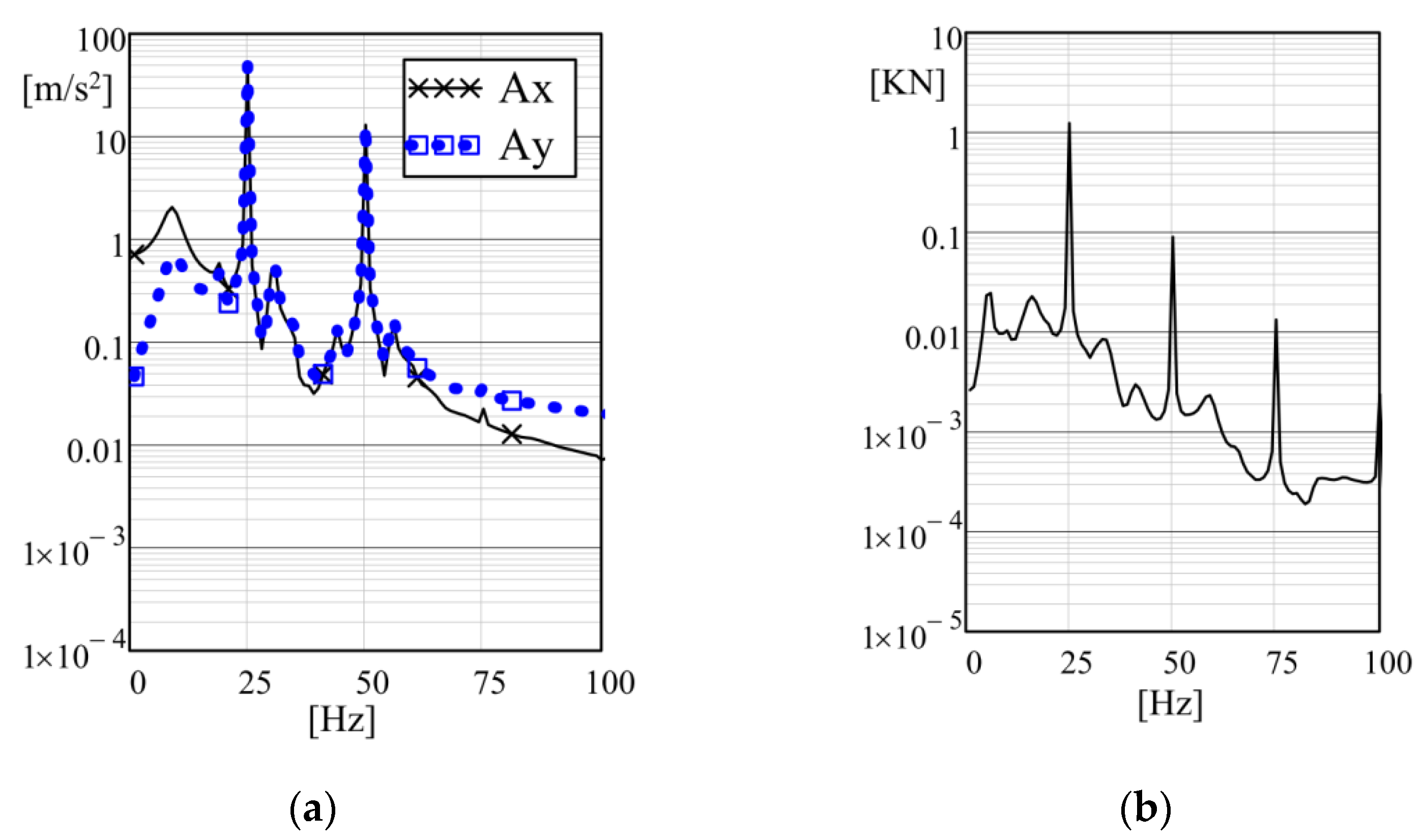
The principal double-frequency mode is realized by the multiple harmonics of the centre of mass acceleration in Figure 18. Their amplitude values of 49.1 m/s2 13 m/s2 at frequencies of 25 Hz and 50 Hz, respectively. This is due to the presence of multiple harmonics of the resulting force shown in Figure 18b.
Comparisons of the main kinematic and force characteristics obtained based on analytical calculations and 3D modeling are given in Table 2. The given results have a good agreement (about 10% on average) and confirm the possibility of realising the vibrator with the optimised kinematic and power parameters for the required loading capacity of a vibrating screen. Certain deviations of dynamical parameters are caused by the non-linear features of supporting springs in the 3D model, which is not accounted for in the analytical calculations.
5. Discussion
The problem of parameters synthesis of static moments of two unbalances under the condition of providing variable periodic force in the range R(t) = 3–6 KN at angular velocities of their rotation ω1 = 157 (314) rad/s and ω2 = 314 (157) rad/s is realized. The existing two combinations of parameter solutions at the angular velocities ratios Kω = 0.5 and Kω = 2 are distinguished by the kinematics of the inertial drive. It is established that the resulting vector of periodic force R(t) rotates around the axis of the vibrator with a variable angular velocity Ω(t), which in the first case varies as 274.8–392.5 rad/s, and in the second case 78.5–196.3 rad/s.
The frequencies of the resulting force R(t) pulsation and its angular velocity Ω(t) are 157 rad/s. The projections of the resulting vector on the coordinate axes allow obtaining different by amplitude and phase periodic horizontal and vertical components. At the stage of dynamic analysis, the numerical calculation of the Duhamel integral was performed to construct the time dependences of displacement and acceleration.
It is established that there are horizontal and vertical displacements in the system, and accelerations in the respective directions have different natures of change with the corresponding sets of multiple harmonics, 25 Hz and 50 Hz. For the case of the angular velocities ratio Kω = 0.5, distorted elliptical trajectories of the centre of mass with a larger amplitude value of the second 50 Hz acceleration harmonic are provided. If the ratio of angular velocities is Kω = 2, elliptical trajectories are smooth with a larger amplitude value of the first 25 Hz acceleration harmonics. In general, the first case is characterized by motion with smaller oscillation amplitudes, with the maximum value of acceleration being the same for both variants in the range of 64–68 m/s2. From this point of view, the first option is more rational.
On the part of the power consumed by the oscillating motion, the answer is ambiguous. The variant with the ratio of the speed Kω = 0.5 is characterized by a constant value of 229 W, which does not depend on the relative phase of the unbalances. In the second case, changing the angle within 0–360° gives a power value of 142–494 W. Changing the initial relative angle between unbalances affects the phases between the acceleration harmonics and does not affect their amplitude values.
The choice of a specific drive option is based on the technological purpose of a particular vibrating machine.
The efficiency of the vibrator is confirmed by the developed physical 3D model of the vibrator for the case Kω = 2. The results of the research showed that at the design stage it is enough to use a linear model, which is convenient and efficient to quickly obtain the result with an error of up to 10% on average for different dynamical parameters. More precise information about the operation of the vibration system can be obtained based on 3D models having physical properties of the bulk material and non-linear stiffness of springs.
6. Conclusions
The conducted research showed the wide scope of positive features inherited by the enhanced design of the dual-motor inertial vibrator. The main advantage is the possibility of tuning the limited number of system parameters to achieve the required vibration characteristics. This is especially useful in the case when the current properties of processed materials are changing significantly.
In distinction to the design previously proposed by the authors and examined in [25], of an inertial vibrator with one electrical motor driving both coaxial rotors simultaneously via the permanent kinematic couplings, the enhanced type of vibrator with separated electrical motors and similar coaxial position of rotating shafts allows for the implementation of online control of vibration parameters by changing the angular speed ratio using the relations derived in this paper.
The wide range of parameters tuning requires only simple control of electrical motors angular rotation speed ratio that allows for more convenient integration of the other types of sensors, which are intended for the measurement of processed material properties (humidity, density, particles fractions and adhesion). In addition, the coaxial placement of two unbalanced rotors allows for matching the excitation force exactly with the centre of mass of the vibrating machine to achieve the required trajectory of motion.
Among the directions of future research is the development of a control function for the vibrators installed on the sieving screens to prevent the large amplitudes of transient vibrations under startup and slow-down conditions while passing the resonance regions. In this way, the Sommerfeld effect can be reduced, especially in vibrating screens and conveyors of large size. Consequently, electrical motors of less power can be installed to reduce the overall power consumption of industrial machines operated far beyond the resonance.
Author Contributions
Conceptualization, V.G.; methodology, V.G., P.K., R.Z.; software, V.K.; validation, V.K.; formal analysis, P.K., R.Z.; investigation, V.K.; writing—original draft preparation, V.G.; writing—review and editing, P.K.; visualization, V.K. All authors have read and agreed to the published version of the manuscript.
Funding
This research received no external funding.
Institutional Review Board Statement
Not applicable.
Informed Consent Statement
Not applicable.
Data Availability Statement
Data supporting reported results can be obtained from the authors.
Conflicts of Interest
The authors declare no conflict of interest.
References
- Czubak, P. Vibratory conveyor of the controlled transport velocity with the possibility of the reversal operations. J. Vibroeng. 2016, 18, 3539–3547. [Google Scholar] [CrossRef] [Green Version]
- Majewski, T. Vibratory forces and synchronization in physical systems. Ing. Mec. Tecnol. Desarro. 2013, 4, 119–128. Available online: http://www.scielo.org.mx/scielo.php?script=sci_arttext&pid=S1665-73812013000100002&lng=es&tlng=en (accessed on 22 December 2021).
- Zhang, X.; Hu, W.; Gao, Z.; Liu, Y.; Wen, B.-C. Composite synchronization on two pairs of vibrators in a far super-resonant vibrating system with the single rigid frame. J. Low Freq. Noise Vib. Act. Control 2021, 40, 2064–2076. [Google Scholar] [CrossRef]
- Hou, Y.; Du, M.; Wang, L. Investigation for synchronization of two co-rotating rotors installed with nonlinear springs in a non-resonance system. Adv. Mech. Eng. 2019, 11, 1687814019834110. [Google Scholar] [CrossRef] [Green Version]
- Blekhman, I.I.; Semenov, Y.A.; Yaroshevych, M.P. On the possibility of designing adaptive vibration machinery using self-synchronizing exciters. Mech. Mach. Sci. 2020, 80, 231–236. [Google Scholar] [CrossRef]
- Liu, Y.; Zhang, X.; Gu, D.; Jia, L.; Wen, B. Synchronization of a dual-mass vibrating system with two exciters. Shock Vib. 2020, 2020, 9345652. [Google Scholar] [CrossRef]
- Zhang, X.; Gu, D.; Yue, H.; Li, M.; Wen, B. Synchronization and stability of a far-resonant vibrating system with three rollers driven by two vibrators. Appl. Math. Model. 2021, 91, 261–279. [Google Scholar] [CrossRef]
- Zhao, G.; Wang, X.; Yu, C.; Liu, S.; Zhou, J.; Zhu, G. Research on static and dynamic characteristics of shear spring of the vibrating flip-flow screen. Symmetry 2020, 12, 1644. [Google Scholar] [CrossRef]
- Michalak, A.; Wodecki, J.; Drozda, M.; Wyłomańska, A.; Zimroz, R. Model of the vibration signal of the vibrating sieving screen suspension for condition monitoring purposes. Sensors 2021, 21, 213. [Google Scholar] [CrossRef]
- Wodecki, J.; Michalak, A.; Wyłomańska, A.; Zimroz, R. Influence of non-Gaussian noise on the effectiveness of cyclostationary analysis—Simulations and real data analysis. Measurement 2021, 171, 108814. [Google Scholar] [CrossRef]
- Musschoot, A. Vibratory Conveyor. Patent US5131525A, 21 July 1992. Available online: https://patents.google.com/patent/US5131525A/en (accessed on 22 December 2021).
- Fuchigami, M. Variable-Force Vibrator. Patent US4108009A, 22 August 1978. Available online: https://patents.google.com/patent/us4108009a/en (accessed on 22 December 2021).
- Braun, G. Unbalance Vibration Generator. Patent US4058019A, 15 November 1977. Available online: https://patents.google.com/patent/EP0730792B1/en (accessed on 22 December 2021).
- Hanggi, G.J. Constant Force Variable Speed Vibrator. Patent US2989869A, 27 June 1961. Available online: https://patents.google.com/patent/US2989869 (accessed on 22 December 2021).
- Chen, B.; Yan, J.; Yin, Z.; Tamma, K. A new study on dynamic adjustment of vibration direction angle for dual-motor-driven vibrating screen. Proc. Inst. Mech. Eng. Part E J. Process Mech. Eng. 2020, 235, 186–196. [Google Scholar] [CrossRef]
- Chen, X.; Liu, J.; Li, L. Dynamics of the vibration system driven by three homodromy eccentric rotors using control synchronization. Appl. Sci. 2021, 11, 7691. [Google Scholar] [CrossRef]
- Jia, L.; Kong, X.; Zhang, J.; Liu, Y.; Wen, B. Multiple-frequency controlled synchronization of two homodromy eccentric rotors in a vibratory system. Shock Vib. 2018, 2018, 4941357. [Google Scholar] [CrossRef]
- Modrzewski, R.; Wodziński, P. Oscillating motion of a double-frequency screen. Gór. Geoinżynieria 2009, 33, 209–219. [Google Scholar]
- Krot, P.; Zimroz, R. Methods of springs failures diagnostics in ore processing vibrating screens. IOP Conf. Ser. Earth Environ. Sci. 2019, 362, 012147. [Google Scholar] [CrossRef]
- Krot, P.; Zimroz, R.; Michalak, A.; Wodecki, J.; Ogonowski, S.; Drozda, M.; Jach, M. Development and verification of the diagnostic model of the sieving screen. Shock Vib. 2020, 2020, 8015465. [Google Scholar] [CrossRef]
- Sorokin, V. Vibrations of a nonlinear stochastic system with a varying mass under near resonant excitation. J. Vib. Control 2019, 26, 1435–1444. [Google Scholar] [CrossRef]
- Yaroshevich, N.; Yaroshevych, O.; Lyshuk, V. Drive dynamics of vibratory machines with inertia excitation. Mech. Mach. Sci. 2021, 95, 37–47. [Google Scholar] [CrossRef]
- Gursky, V.; Krot, P.; Dilay, I.; Zimroz, R. Optimization of the vibrating machines with adjustable frequency characteristics. In Nonstationary Systems: Theory and Applications. WNSTA 2021. Appl. Cond. Monit. 2022, 18, 352–363. [Google Scholar] [CrossRef]
- Cieplok, G. Amplituda drgań symetrycznie posadowionej maszyny wibracyjnej podczas rezonansu przejściowego (Vibration amplitude of a symmetrically mounted vibrating machine during transient resonance). Czas. Tech. Mech. 2008, 105, 37–45. [Google Scholar]
- Czubak, P.; Surówka, W. Influence of the excitation frequency on operations of the vibratory conveyor allowing for a sudden stopping of the transport. Vib. Phys. Syst. 2020, 31, 1–12. [Google Scholar] [CrossRef]
- Yatsun, V.; Filimonikhin, G.; Dumenko, K.; Nevdakha, A. Search for two-frequency motion modes of single-mass vibratory machine with vibration exciter in the form of passive auto-balancer. East.-Eur. J. Enterp. Technol. 2017, 6, 1729–4061. [Google Scholar] [CrossRef] [Green Version]
- Lanets, O.; Kachur, O.; Korendiy, V.; Lozynskyy, V. Controllable crank mechanism for exciting oscillations of vibratory equipment. In DSMIE 2021: Advances in Design, Simulation and Manufacturing IV, Proceedings of the 4th International Conference on Design, Simulation, Manufacturing, Lviv, Ukraine, 8–11 June 2021; Lecture Notes in Mechanical Engineering; Springer: Cham, Switzerland, 2021; pp. 43–52. [Google Scholar] [CrossRef]
- Gursky, V.; Kuzio, I.; Krot, P.; Zimroz, R. Energy-Saving Inertial Drive for Dual-Frequency Excitation of Vibrating Machines. Energies 2021, 14, 71. [Google Scholar] [CrossRef]
- Wang, N.; Jiang, D.; Xu, H. Dynamic characteristics analysis of a dual-rotor system with inter-shaft bearing. Proc. Inst. Mech. Eng. Part G J. Aerosp. Eng. 2017, 233, 095441001774896. [Google Scholar] [CrossRef]
- Wang, Z.; Zhang, B.; Zhang, K.; Yue, G. Optimization and experiment of mass compensation strategy for built-in mechanical on-line dynamic balancing system. Appl. Sci. 2020, 10, 1464. [Google Scholar] [CrossRef] [Green Version]
- Li, B.; Zhou, H.; Liu, J.; Kang, C. Modeling and dynamic characteristic analysis of dual rotor-casing coupling system with rubbing fault. J. Low Freq. Noise Vib. Act. Control 2021, 14613484211039322. [Google Scholar] [CrossRef]
- Liu, J.; Wang, C.; Luo, Z. High dimensional nonlinear spring characteristic modelling and vibration analyses of subharmonic resonance of a dual-rotor system based on energy tracks. Appl. Math. Model. 2021, 91, 390–411. [Google Scholar] [CrossRef]
- Kroger, D. Unbalanced Mass Vibration Generator. Patent US5850110A, 15 December 1998. Available online: https://patents.google.com/patent/US5850110 (accessed on 22 December 2021).
- Nazarenko, I.; Gaidaichuk, V.; Dedov, O.; Diachenko, O. Investigation of vibration machine movement with a multimode oscillation spectrum. East.-Eur. J. Enterp. Technol. 2017, 6, 28–36. [Google Scholar] [CrossRef] [Green Version]
- Kuzo, I.V.; Lanets, O.V.; Gursky, V.M. Substantiation of technological efficiency of two-frequency resonant vibration machines with pulse electromagnetic disturbance. Nauk. Visnyk Natsionalnoho Hirnychoho Universytetu 2013, 3, 71–77. [Google Scholar]
- Gursky, V.M.; Kuzio, I.V.; Lanets, O.S.; Kisała, P.; Tolegenova, A.; Syzdykpayeva, A. Implementation of dual-frequency resonant vibratory machines with pulsed electromagnetic drive (Implementacja systemów rezonansowych o dwóch częstotliwościach z wieloma częstotliwościami drgań własnych). Prz. Elektrotech. 2019, 95, 41–46. [Google Scholar] [CrossRef]
- Gursky, V.; Kuzio, I. Strength and durability analysis of a flat spring at vibro-impact loadings. East.-Eur. J. Enterp. Technol. 2016, 5, 4–10. [Google Scholar] [CrossRef]
- Krot, P.V. Dynamical processes in a multi-motor gear drive of heavy slabbing mill. J. Vibroeng. 2019, 21, 2064–2081. [Google Scholar] [CrossRef] [Green Version]
- Angeles, J. Dynamic Response of Linear Mechanical Systems: Modeling, Analysis and Simulation; Springer: Boston, MA, USA, 2012; 560p. [Google Scholar] [CrossRef]
Figure 1.
Kinematic scheme of dual-frequency inertial vibration exciter: 1, 2—unbalanced masses; 3—housing; 4—bearing units; 5, 6—electric motors; 7, 8—tooth belts transmission; 9—encoders.
Figure 1.
Kinematic scheme of dual-frequency inertial vibration exciter: 1, 2—unbalanced masses; 3—housing; 4—bearing units; 5, 6—electric motors; 7, 8—tooth belts transmission; 9—encoders.

Figure 2.
Hodograph of the vector of the resulting excitation force R(t), (KN) of the inertial vibrator for the initial phase shift angle ϕ = 0: (a) Kω = 0.5; (b) Kω = 2.
Figure 2.
Hodograph of the vector of the resulting excitation force R(t), (KN) of the inertial vibrator for the initial phase shift angle ϕ = 0: (a) Kω = 0.5; (b) Kω = 2.
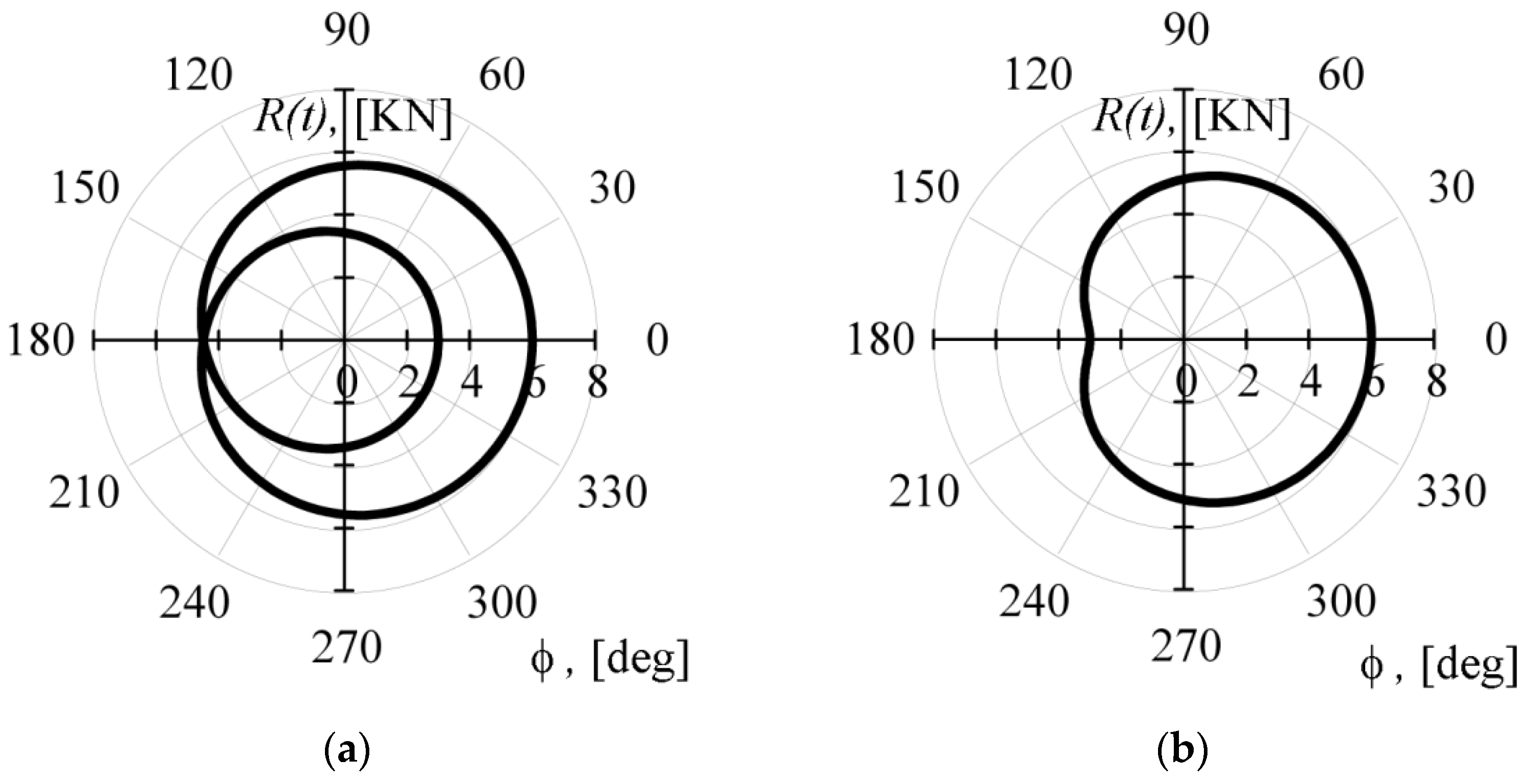
Figure 3.
Time dependences of the angular velocity Ω(t) of the resulting perturbation force vector R(t) of the inertial vibrator: (a) Kω = 0.5; (b) Kω = 2.
Figure 3.
Time dependences of the angular velocity Ω(t) of the resulting perturbation force vector R(t) of the inertial vibrator: (a) Kω = 0.5; (b) Kω = 2.
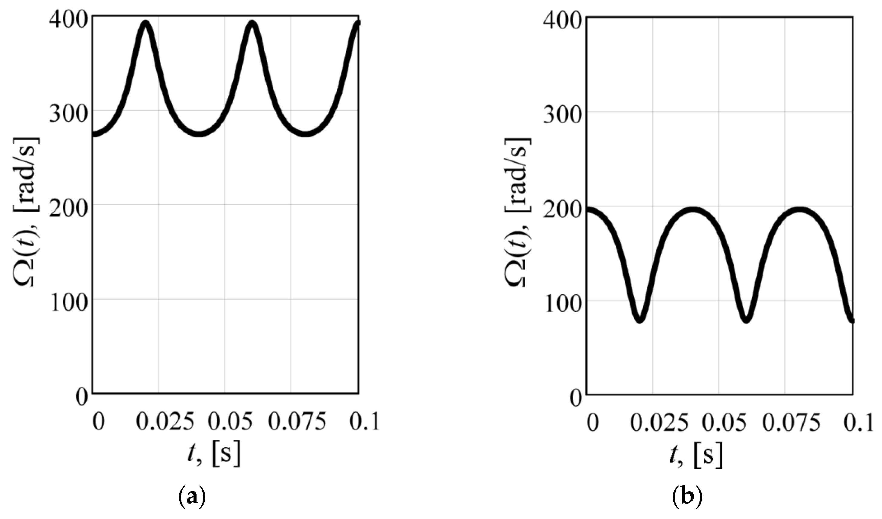
Figure 4.
Time dependences of the resulting perturbation force R(t) and its angle ϕ(t) of the inertial vibrator: (a) Kω = 0.5; (b) Kω = 2.
Figure 4.
Time dependences of the resulting perturbation force R(t) and its angle ϕ(t) of the inertial vibrator: (a) Kω = 0.5; (b) Kω = 2.
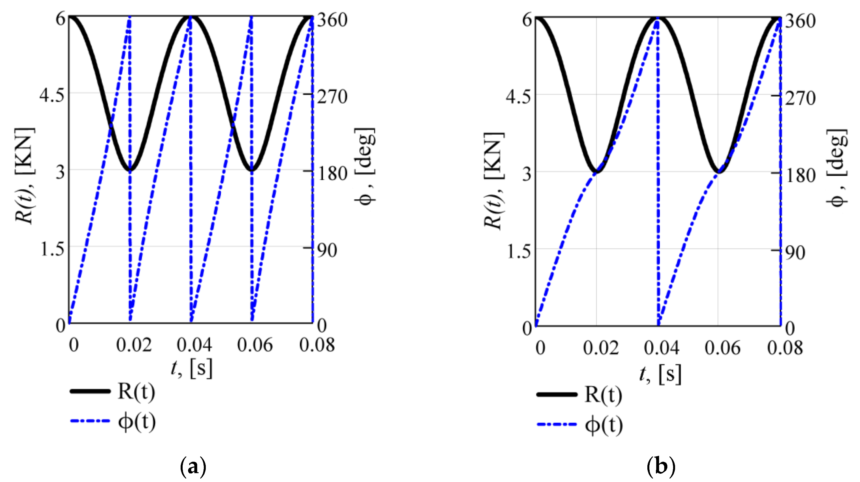
Figure 5.
Time dependences of the projections Rx(t) and Ry(t) of the resulting force vector on the coordinate axes: (a) Kω = 0.5; (b) Kω = 2.
Figure 5.
Time dependences of the projections Rx(t) and Ry(t) of the resulting force vector on the coordinate axes: (a) Kω = 0.5; (b) Kω = 2.
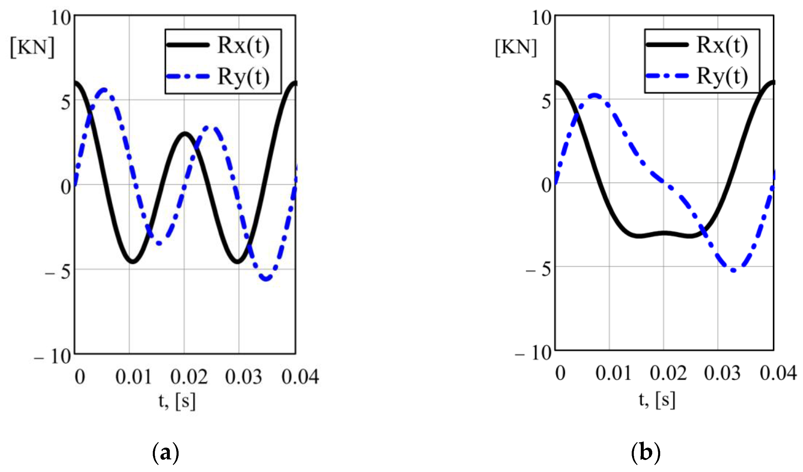
Figure 6.
Calculation scheme of the vibrating screen.

Figure 7.
The trajectories of the centre of mass: (a) Kω = 0.5; (b) Kω = 2.
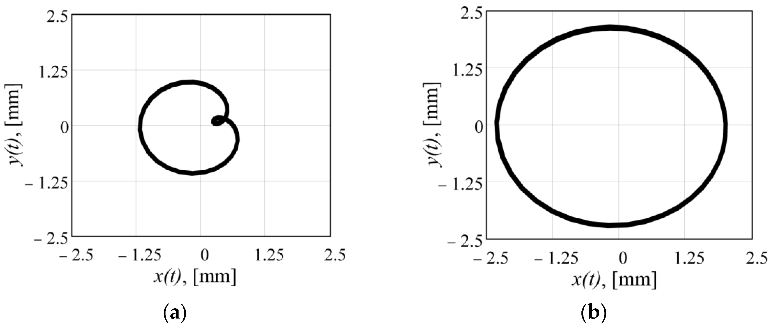
Figure 8.
Acceleration of the centre of mass: (a) Kω = 0.5; (b) Kω = 2.

Figure 9.
Time dependences of acceleration of the centre of mass: (a) Kω = 0.5; (b) Kω = 2.

Figure 10.
Amplitude (a) and phase (b) frequency domain characteristics of the acceleration of the centre of mass for Kω = 0.5.
Figure 10.
Amplitude (a) and phase (b) frequency domain characteristics of the acceleration of the centre of mass for Kω = 0.5.
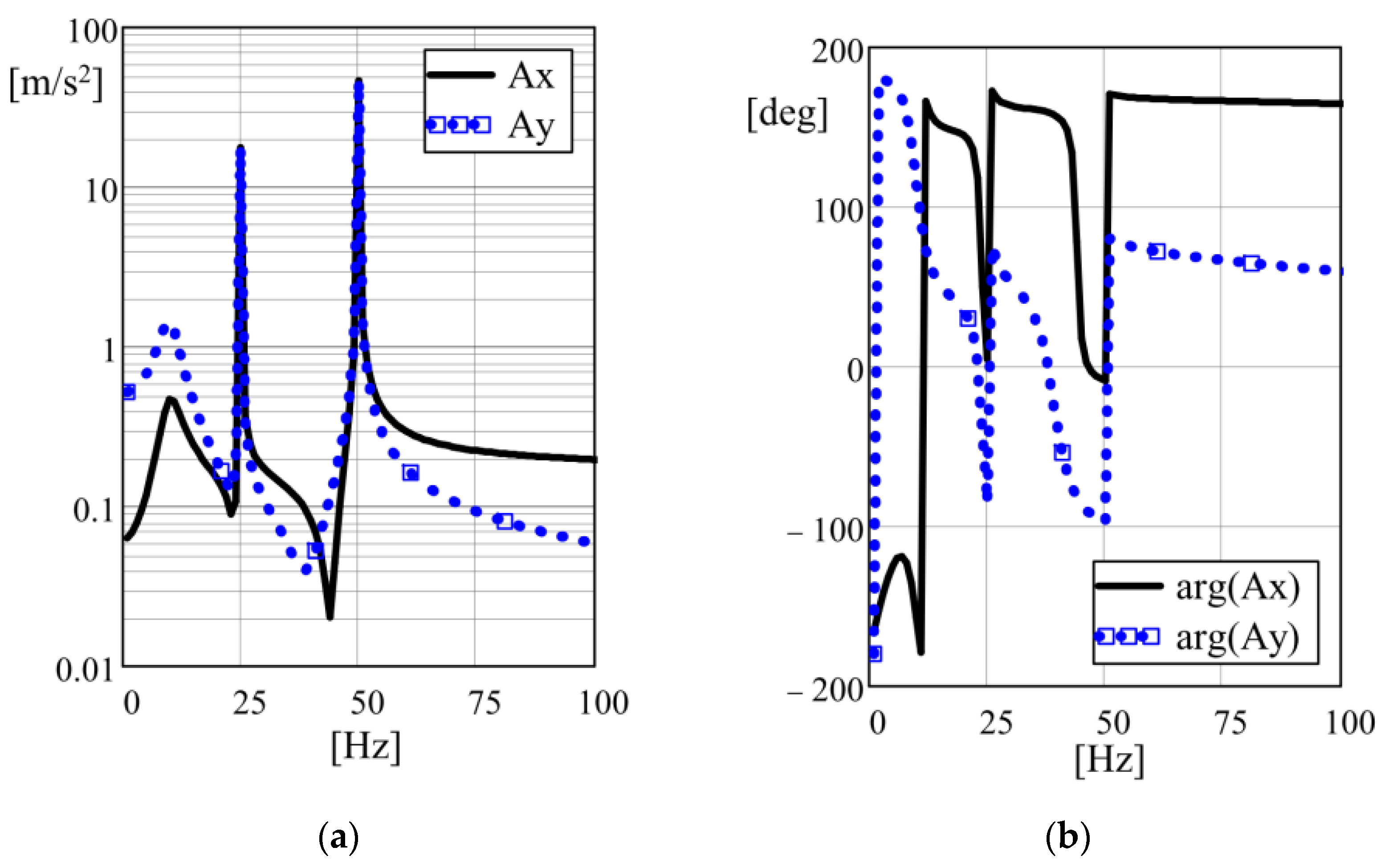
Figure 11.
Amplitude (a) and phase (b) frequency domain characteristics of the acceleration of the centre of mass for Kω = 2.
Figure 11.
Amplitude (a) and phase (b) frequency domain characteristics of the acceleration of the centre of mass for Kω = 2.
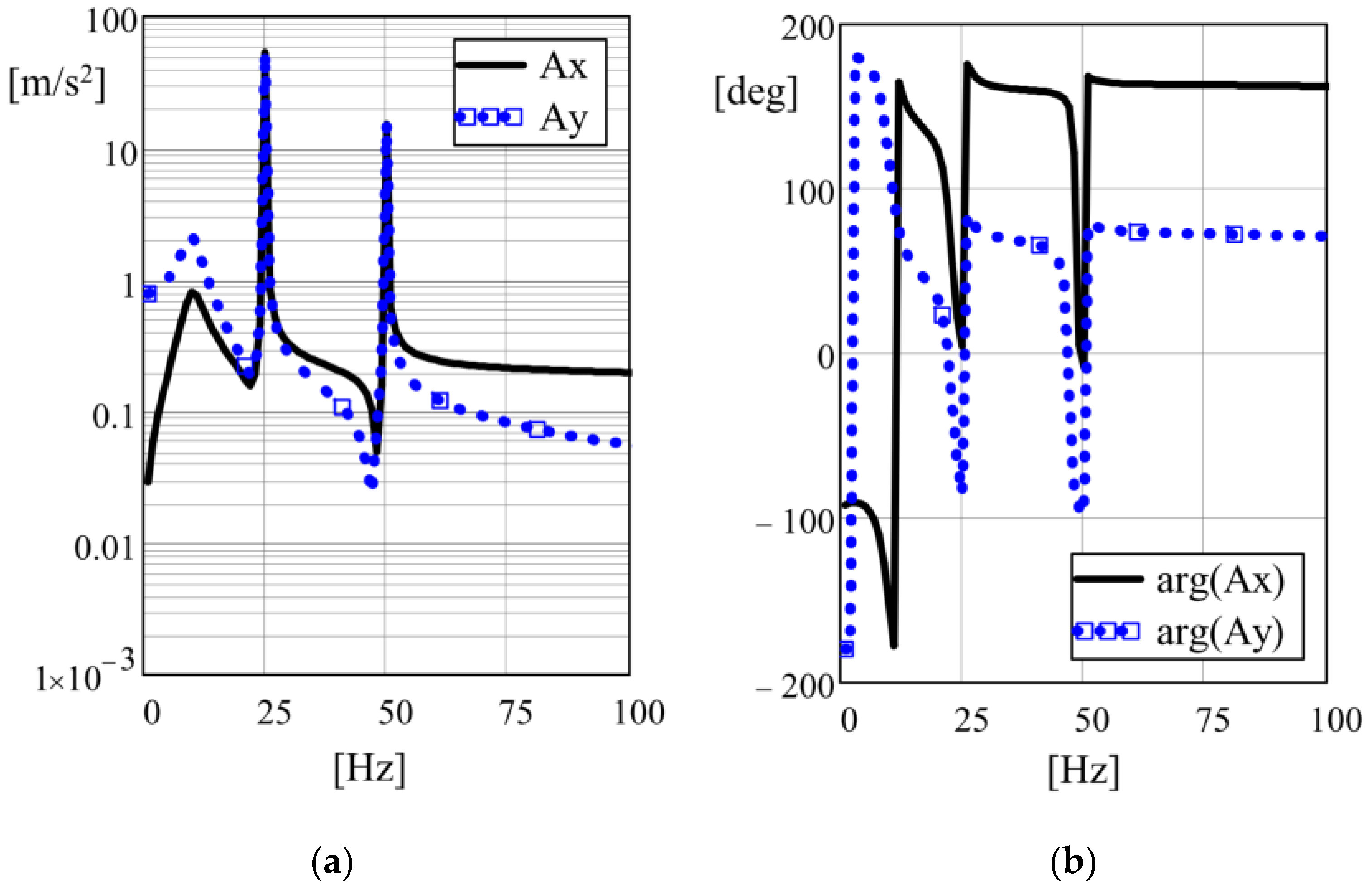
Figure 12.
Power of the inertial vibrator pvib, (W) depending on the angle of the initial phase shift between the individual unbalances: (a) Kω = 0.5; (b) Kω = 2.
Figure 12.
Power of the inertial vibrator pvib, (W) depending on the angle of the initial phase shift between the individual unbalances: (a) Kω = 0.5; (b) Kω = 2.

Figure 13.
3D model of vibrator: (a) general view; (b) design dimensions.
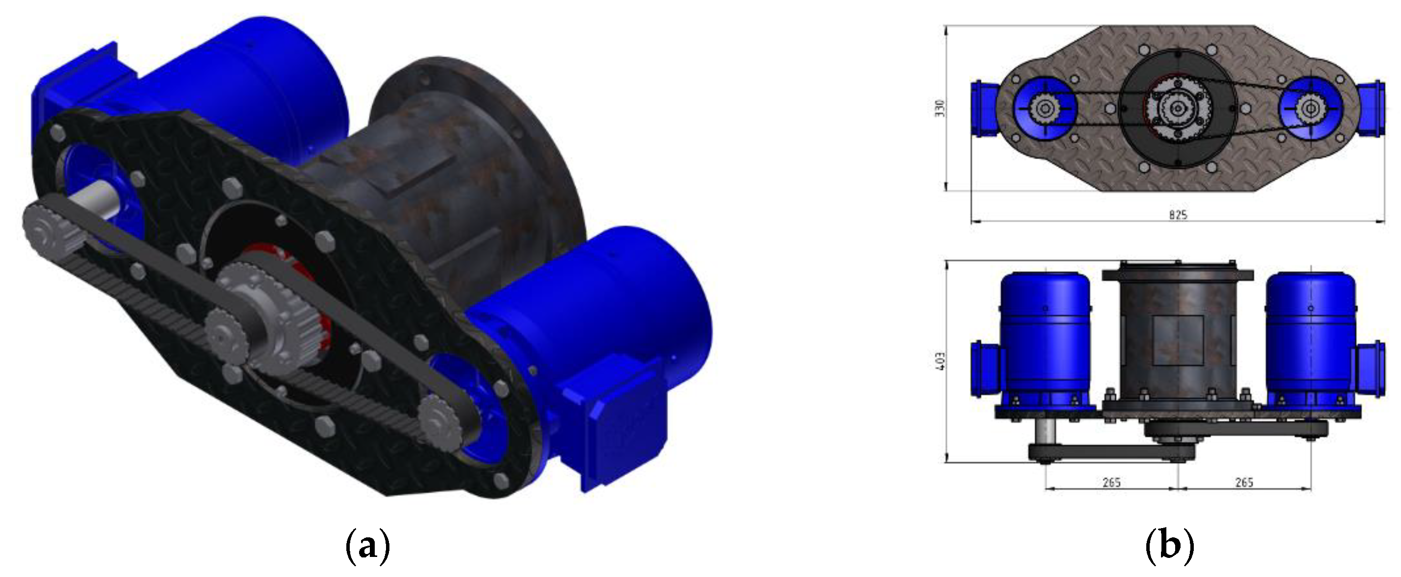
Figure 14.
Dynamic model of vibrator: (a) initial position; (b) one of the intermediate positions of unbalances.
Figure 14.
Dynamic model of vibrator: (a) initial position; (b) one of the intermediate positions of unbalances.
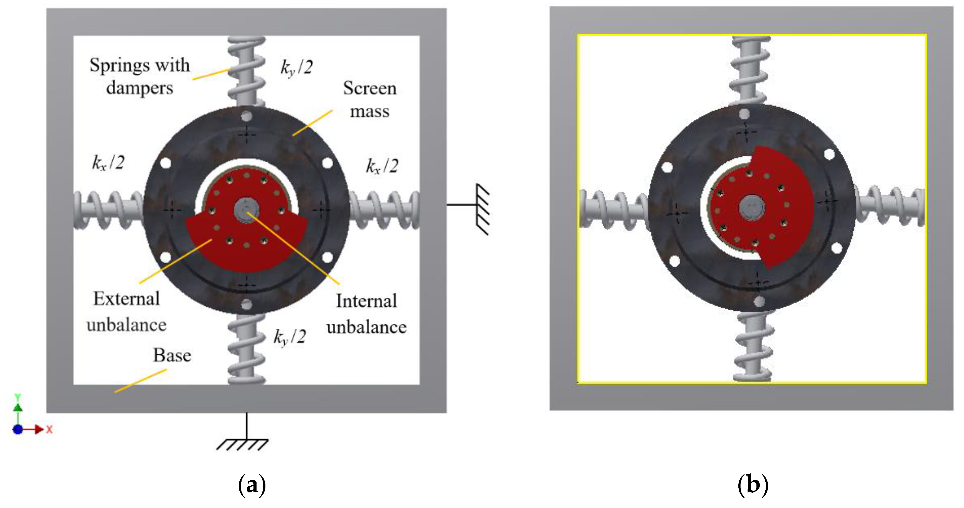
Figure 15.
The displacement trajectory of the centre of mass on the 3D model.

Figure 16.
The acceleration trajectory of the centre of mass on the 3D model.
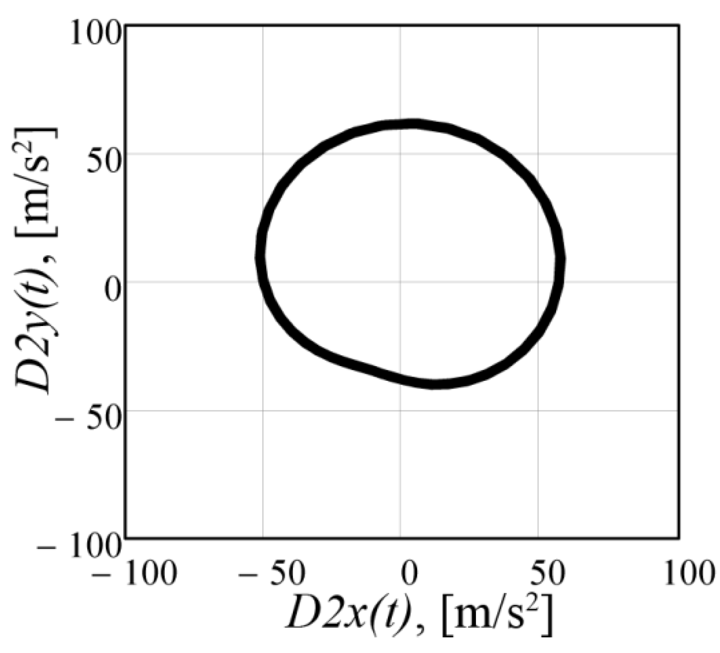
Figure 17.
Time dependence: (a) resulting force R(t), [KN]; (b) dynamic power pvib, (W).
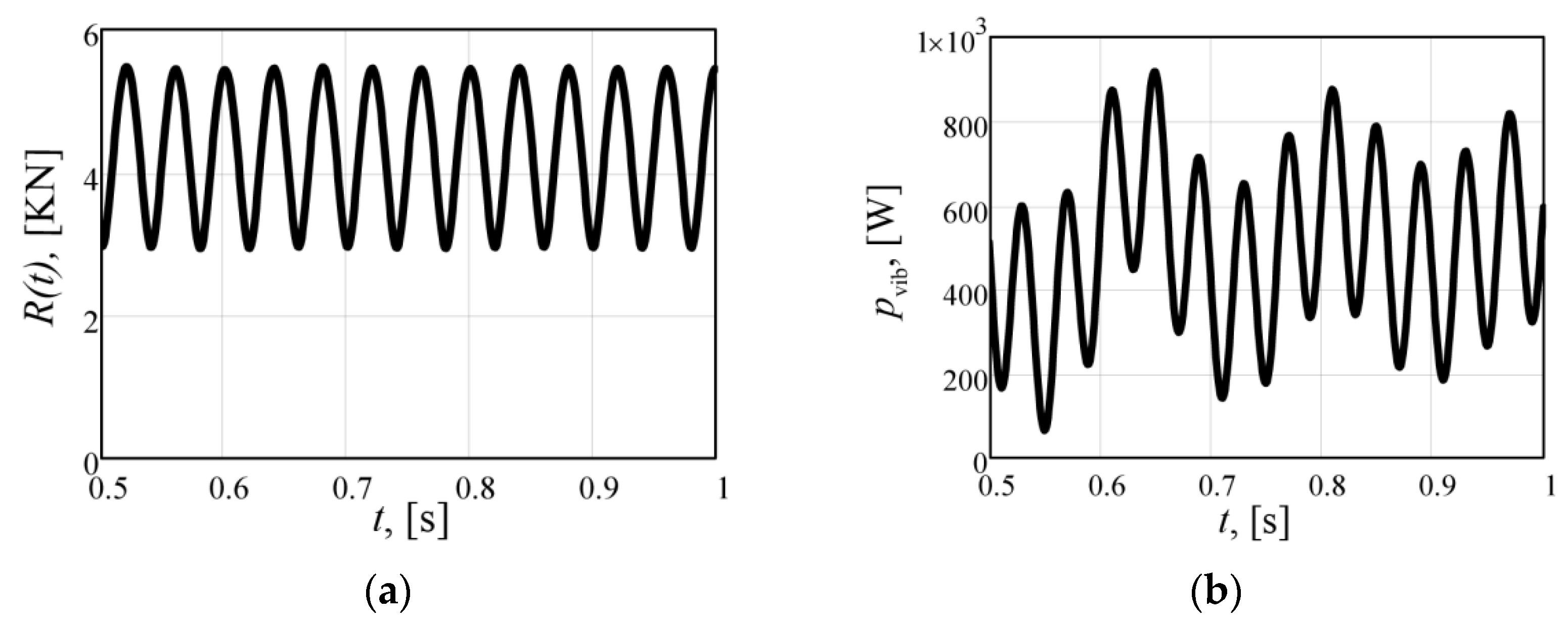
Figure 18.
Amplitude frequency domain characteristics: (a) acceleration of the centre of mass; (b) resulting force.
Figure 18.
Amplitude frequency domain characteristics: (a) acceleration of the centre of mass; (b) resulting force.

Table 1.
Comparative characteristics of vibrators.
| Parameters | Kω = 0.5 | Kω = 2 | Kω = 1 | Kω = 1 |
|---|---|---|---|---|
| Static moment of unbalances 1/2, kg · m | 0.061/0.046 | 0.015/0.183 | 0.061/0 | 0.243/0 |
| Angular velocity 1/2, rad/s | 157/314 | 314/157 | 314/0 | 157/0 |
| Perturbation force, KN | 3–6 | 3–6 | 6 | 6 |
| Total oscillating mass, kg | 100 | 100 | 100 | 100 |
| Maximum amplitude, mm | 1.2 | 2.3 | 0.65 | 2.9 |
| Harmonics amplitude 25/50 Hz, m/s2 | 17.6/46.3 | 52.7/15.3 | 0/61.8 | 70.3/0 |
| Dynamic power of the vibrator, W | 229 | 142–494 | 120 | 276 |
Table 2.
Comparative of vibrator characteristics by the analytical functions and 3D model.
| Parameters | Modeling | Error, % | |
|---|---|---|---|
| Analytical | 3D Model | ||
| Perturbation force, KN | 3–6 | 2.9–5.7 | 3-5 |
| Maximum amplitude, mm | 2.3 | 2.1 | 10 |
| Harmonics amplitude 25/50 Hz, m/s2 | 52.7/15.3 | 49.1/13 | 7–15 |
| Dynamic power of the vibrator, W | 172.7 | 190 | 10 |
Publisher’s Note: MDPI stays neutral with regard to jurisdictional claims in published maps and institutional affiliations. |
© 2022 by the authors. Licensee MDPI, Basel, Switzerland. This article is an open access article distributed under the terms and conditions of the Creative Commons Attribution (CC BY) license (https://creativecommons.org/licenses/by/4.0/).
Share and Cite
MDPI and ACS Style
Gursky, V.; Krot, P.; Korendiy, V.; Zimroz, R. Dynamic Analysis of an Enhanced Multi-Frequency Inertial Exciter for Industrial Vibrating Machines. Machines 2022, 10, 130. https://doi.org/10.3390/machines10020130
AMA Style
Gursky V, Krot P, Korendiy V, Zimroz R. Dynamic Analysis of an Enhanced Multi-Frequency Inertial Exciter for Industrial Vibrating Machines. Machines. 2022; 10(2):130. https://doi.org/10.3390/machines10020130
Chicago/Turabian StyleGursky, Volodymyr, Pavlo Krot, Vitaliy Korendiy, and Radosław Zimroz. 2022. "Dynamic Analysis of an Enhanced Multi-Frequency Inertial Exciter for Industrial Vibrating Machines" Machines 10, no. 2: 130. https://doi.org/10.3390/machines10020130
Note that from the first issue of 2016, this journal uses article numbers instead of page numbers. See further details here.