
Dynamic Analysis of a High-Contact-Ratio Spur Gear System with Localized Spalling and Experimental Validation

1
School of Mechanical Engineering, Hefei University of Technology, Hefei 230009, China
2
School of Mechanical and Vehicle Engineering, West Anhui University, Luan 237012, China
3
AnHui Key Laboratory of Digit Design and Manufacture, Hefei 230009, China
4
AnHui Province Key Lab of Aerospace Structural Parts Forming Technology and Equipment, Hefei 230009, China
*
Author to whom correspondence should be addressed.
Machines 2022, 10(2), 154; https://doi.org/10.3390/machines10020154
Submission received: 12 January 2022
/
Revised: 11 February 2022
/
Accepted: 14 February 2022
/
Published: 18 February 2022
(This article belongs to the Special Issue Reliability of Mechatronic Systems and Machine Elements: Testing and Validation)
Abstract
:The dynamic characteristics and tooth spalling fault features are studied for the high-contact-ratio spur gear bearing system. The bending torsional dynamic model is proposed in this study for the gear bearing system with an ellipsoid spalling fault. This model also considers time-varying meshing stiffness, tooth friction, fractal gear backlash, and comprehensive transmission error. The meshing stiffness of the system is evaluated using the potential energy method. The bifurcation diagram, time-domain waveform, Poincaré map, phase map, frequency spectrum, and related three-dimensional map are used as tools to analyze the system’s dynamic response qualitatively. The results reveal that the system’s motion with ellipsoid tooth spalling defect exhibits rich dynamic behavior. The response of the proposed dynamic model is consistent with experimental results in the frequency domain. Therefore, the developed dynamic model can predict the system’s vibration behavior with localized spalling fault. Hence, it could also provide a theoretical foundation for future spall defect diagnosis of the gear transmission system.
1. Introduction
The contact ratio is an important index to indicate the smoothness and the uniformity of the gear system’s transmission load [1]. By increasing the addendum coefficient, enhancing the number of teeth, reducing the pressure angle, and adjusting the modification coefficient, an involute spur gear with a contact ratio greater than two can be obtained, called high-contact-ratio spur gear [2]. Compared with standard gears, high-contact-ratio spur gear has more pairs of teeth meshing at the same time. As a result, high-contact-ratio gear has the advantages of high load carrying capacity [3]. Thus, it is widely used in automobiles, power tools, and other fields. As a common failure form of gear, tooth spalling is frequently encountered under excessive load, which initially occurs at the local position of the tooth surface. Localized tooth spalling induces serious damage to the gear transmission system gradually. Three main aspects are considered while characterizing tooth spalling fault: meshing stiffness, dynamic characteristics, and experimental validation. The model of damaged gear pairs is analyzed to estimate the mesh stiffness. The mesh stiffness is imported into the gear dynamic model to evaluate the non-linear dynamic characteristics. The dynamic response obtained from the simulation is compared with the experimental results to verify the dynamic model.
Tooth spalling affects the tooth profile and results in a change of meshing stiffness. Several researchers have developed many methods to estimate the meshing stiffness of the gears. Wang [4] and Zhan [5] have developed the finite element methods. The finite element method can accurately simulate the contact state of the system, but it is time-consuming. The analytical method is very efficient in terms of computation [6]. For example, Sun [7] studied the mesh stiffness of spur gear pairs with tooth modifications based on the thin slice assumption. For the gear with rectangular tooth spalling, Chaari researched the mesh stiffness of spur-gear pair [8], Jiang [9] and Han [10] studied the helical gear, while Luo studied the planetary gear [11]. In references [12,13], the meshing stiffness of gears with rectangular spalls of various widths, lengths, and positions were compared. Saxena et al. [14] estimated gear mesh stiffness for rectangular, circular, and V-shaped spalling. It is assumed that the bottom of the tooth spalling is flat in the literature. In practice, the shape of the tooth spall usually has a curvilinear bottom with a gradually changing dent depth rather than a suddenly decreased tooth thickness. Compared to rectangular solid, the ellipsoid is close to the actual geometry of the tooth spalling. This geometric model makes the calculation of mesh stiffness more accurate. The mesh stiffness of the gear with ellipsoid tooth spall is analyzed in detail in this work.
The estimation of mesh stiffness lays a foundation for gear dynamics. Dynamic analysis is valuable for operating status monitoring and gear fault diagnosis [15,16]. Using statistical methods to evaluate spall severity was suitable under low velocity and low excitation [17]. Dadon et al. [18] researched the effect of different gear imperfections on fault detection. Ma and Chen [19] studied the differences in vibration signals of tooth crack and tooth spall. Modification coefficients were introduced to research the impact of the spalls on gear dynamics [20]. Chen et al. [21] compared the mesh characteristics of helical gears with spalling faults using analytical and finite-element methods. Based on the theoretical and experimental study, Huangfu et al. [22] investigated the meshing and dynamic characteristics of a spalled gear system. Luo et al. [23] demonstrated that tooth spall and sliding friction have an evident effect on kinetic performance. Shi et al. [24] discussed the dynamic characteristics of the gear with double-teeth spalling fault. In terms of global dynamics, Ma [25] employed the singularity theory to evaluate the bifurcation characteristics of the gear system with tooth spalling.
Two drawbacks in these previous models are found. Mesh stiffness of the high-contact-ratio gear with ellipsoid spalling defects is not calculated. Secondly, motion state analysis of the gear with localized spalling defects under excitation frequency and gear backlash is not considered. The above deficiencies are the main contributions of this study. Highlights of this paper are listed as follows.
- (1)
- Modeling of the mesh stiffness of the high-contact-ratio gear system with localized ellipsoid spalling.
- (2)
- Bifurcation characteristic of the high-contact-ratio gear system with localized ellipsoid tooth spalling fault is discussed.
- (3)
- Experiments are carried out for vibration measurement to validate the proposed dynamic model.
The rest of the article is arranged as follows. Section 2 describes the modeling of the mesh stiffness through the precise tooth profile equation of the high-contact-ratio gear and the ellipsoid equation. Section 3 illustrates the proposed dynamic model of the gear-bearing system. Section 4 discusses the numerical results. Section 5 is about the vibration experiments. The conclusions are presented in Section 6.
2. Mesh Stiffness Computation
The alternating meshing process of two and three gear pairs causes the variation of mesh stiffness. It also plays the role of internal excitation of the gear system. It is of great significance to develop an analytical model to calculate the mesh stiffness.
2.1. Accurate Tooth Profile Equation
The tooth profile of high contact ratio gear comprises tooth tip arc line, involute tooth profile, and tooth root transition curve. The motion of a rack-type cutting tool is equivalent to the meshing of the rack and pinion. In the process of machining, the cutter’s machining pitch line is always tangent to the gear’s machining pitch circle [26]. The profile of the rack-type cutting tool is shown in Figure 1. As presented in Figure 2, during gear machining, the involute part of the tooth profile is cut directly by the straight part of the cutter (BC), and the fillet part of the cutter (AB) cuts the transition part. The transition part is the isometric curve of the extended involute. This extended involute is depicted by the center of the tool’s rounded corner. An x–y coordinate system with the center of the gear as the origin is shown. The gear teeth are usually considered as a cantilever beam of a variable cross-section. The coordinates of any contact point: i, on the involute part are expressed as follows.
rb denotes the radius of the gear base circle. αi is the working load angle acting on the contact point: i. θb is half of the tooth base arc angle (θb = (π/2 + 2X·tanα0)/N + invα0). x is the displacement coefficient. N is the number of teeth. inv(·) represents the involute function of the pressure angle. Coordinates of point: j, on the transition curve are defined as follows.
r and rρ are the radii of the gear pitch and the top corner of the tool, respectively. a is the distance from the center of the top corner to the center line of the tool (a = (ha* + c*)m − rρ, a1 = a − xm, φ = (a1/tanγ + b)/r, b = πm/4 + ha*·m·tanα0 + rρ·cosα0).
2.2. Analytical Model of Meshing Stiffness
Many tooth surface spalls have progressively varying depth and a curved base surface in practice as shown in Figure 3. The ellipsoid tooth spall is formed by removing the intersection of the gear and the ellipsoid. As shown in Figure 4, the ellipsoid tooth spall’s maximum width, length, and center depth are ws, ls, and hs, respectively. The starting and ending position is denoted by xstart and xend, respectively. θs is the angle between the tangent of tooth spall and involute curve. In this work, the position (xstart, θs) and the severity (ws, ls, hs) are fixed.
Table 1 displays the comparison of key geometry parameters of the ellipsoid tooth spall for healthy and spall gear.
An ellipsoid’s parametric function is defined as follows.
a, b, and c are the radii of the ellipsoid along x, y, and z axis. Equations (4) and (5) are derived assuming a and b as equal.
In the x–y plane, the coordinates of the ellipsoid center are derived as follows.
Figure 4b shows the cross-section of the ellipsoid tooth spall at a distance x, The ellipse equation is as follows.
The length lxs is calculated is expressed as follows.
As shown in Figure 4b, hx is the half-height of the gear tooth cross-section at a distance x. The gear tooth contact length Le is given as follows.
L denotes the gear tooth width. The maximum depth of the ellipsoid tooth spall at a distance x is determined as follows.
The corresponding area of the portion of the ellipse is deduced as follows.
The cross-section area Ax of the ellipsoid tooth spall at a distance x is given below.
Ax causes a shift in the cross-neutral section’s axis. The corresponding displacement δxs between these two central axes is calculated as follows.
The area moment of inertia of the ellipse segments is expressed as follows.
Under the tooth spall conditions, the area moment of inertia of the gear tooth cross-section with respect to the new axis is modified as follows.
Figure 5 shows the gear profile. Segments AB and BC represent the transition curve and involute curve, respectively. P is the meshing point, and the corresponding pressure angle is αp. F denotes the meshing force that is decomposed into Fx and Fy, respectively. Based on the potential energy method [27], comprehensive mesh stiffness k(t) is deduced.
Subscript i (i = 1, 2, 3) denotes the pair of the engaging gear tooth. Based on the tooth profile equations, each of the stiffness is expressed as follows.
E, G, and υ stand for Young’s modulus, shear modulus, and Poisson’s ratio, respectively. A1 and I1 denote the cross-sectional area and corresponding inertia within the transition curve, respectively. A2, A4 and I2, I4 are the cross-sectional areas of the healthy part of the involute curve and the related area moments of inertia. For the spall part of the gear profile, A3 and I3 are evaluated by Equations (14) and (17), respectively. uf, sf, L*, M*, P,* and Q* are given in reference [28].
Figure 6 shows the curve of mesh stiffness. The incidence of tooth spall reduces the mesh stiffness. A localized spall fault is considered. Hence, it occurs once per revolution. Thus, compared with the healthy gear, the reduction in mesh stiffness occurs mainly in the double-tooth and the triple-tooth zones.
3. Dynamic Model of System
The support of the rolling bearing is assumed to be rigid. The gear-bearing translation-torsion dynamic lumped parameter model is established, as is shown in Figure 7, considering the influence of gear backlash, damping, comprehensive transmission error, friction force, and time-varying meshing stiffness.
3.1. Gear-Bearing System
m, I, T, and θ represent the mass, moment of inertia, torque, and torsional angular displacement, respectively. Subscripts p and g indicate quantities associated with pinion and gear, respectively. rb, kx, and ky denote the base circle radius, vertical radial support stiffness, and horizontal radial support stiffness. The time-varying meshing stiffness, meshing damping, and backlash of the gear pair are expressed by km, cm, and 2b, respectively. e(t) is the comprehensive static error along the tangent direction of the gear base circle.
As shown in Figure 7, the dynamic model has six degrees of freedom, including two rotational degrees of freedom and four translational degrees of freedom along with the horizontal and vertical directions. The generalized coordinate array is expressed as follows.
3.2. Dynamic Meshing Force and Frictional Force
The relative displacement between pinion and gear along the line of action is expressed as follows.
The dynamic meshing force between gears consists of elastic meshing forces caused by time-varying stiffness and viscous meshing forces caused by meshing damping, denoted as follows.
The gap function formula can be calculated as follows.
b0, λ, Ra1/Ra2, and D1/D2 denote initial gear backlash, characteristic scale coefficient, actual surface roughness, and fractal dimension, respectively. Rac(D) is the function to get the corresponding Ra with a particular fractal dimension, which can be obtained from the reference [30]. The friction force between tooth surfaces during gear meshing is deduced as follows.
The direction of friction is variable, and the direction coefficient depends on the following formula.
Friction force arms (Figure 8) are deduced as follows.
The friction coefficient is related to relative sliding velocity, tooth surface roughness, contact pressure, lubrication situation, etc. Hence, it is particularly difficult to predict the friction coefficient value. The tooth friction model mainly includes the Coulomb friction model, Buckingham empirical formula, Benedict Kelly model, and the friction model based on Elastohydrodynamic lubrication (EHL) theory. Among these, the friction model proposed by Xu [31] reasonably agrees with the measured data, so it is usually adopted to predict the friction coefficient in this paper. It is based on non-Newtonian, thermal EHL theory, and multiple linear regression analysis. The friction coefficient calculation results are shown in Figure 9.
The friction torque on the gear can be expressed as follows.
3.3. Differential Equations of Motion
Based on the time-varying meshing stiffness, transmission error, the fractal backlash, the frictional force, and Newton’s law of motion, the differential equation of vibration motion of the gear-bearing coupling system is deduced as follows.
Setting x1 = θp, x2=x1′, x3 = θg, x4 = x3′, x5 = xp, x6 = x5′, x7 = xg, x8 = x7′, x9 = yp, x10 = x9′, x11 = yg, and x12 = x11′, the above equation is transformed into the following form.
4. Numerical Simulation and Discussion
The high-contact-ratio gear system is non-linear. Table 2 lists its main parameters. The parameters in blue boxes are gear basic parameters. Gear basic parameters were designed via the KISSsoft software. Mesh damping ratio was obtained from the reference [32]. Additionally, the other parameters were calculated from the gear system via the Solidworks software. The fourth-order Runge–Kutta numerical integration method is used to solve the above differential equations of the system through the MATLAB software. The simulated data are processed for generating a bifurcation diagram, three-dimensional frequency spectrum, Poincaré map, phase map, etc.
4.1. Effect of Excitation Frequency
Gear excitation frequency often changes with working conditions. It is one of the key parameters affecting the dynamic characteristics of the gear system and is often used as a variable parameter to compare the systematic dynamical performance. Here, surface roughness Ra is taken equal to 0.8 μm, and fractal dimensions D1 and D2 are equivalent to 1.1. Figure 10 shows the bifurcation characteristics of the lateral displacement (xp) of the pinion changing with the excitation frequency Ω. Its three-dimensional frequency map is illustrated in Figure 11. Both figures reach an agreement on systematic bifurcation behaviors.
The system is in periodic motion at low excitation frequency, as shown in Figure 12a,b. When Ω equals 0.6218, resonance occurs in the system. The system enters chaotic regions A1, A2, and A3 sequentially with the increasing excitation frequency. The system follows quasi-periodic motion between the chaotic regions, as shown in Figure 12e to Figure 12h. How the systems enter chaos is different. The system enters chaotic region A1 through quasi-periodic motion, as shown in Figure 12c,d. However, the system enters chaotic regions A2 and A3 by way of crisis, as shown in Figure 12i–l.
As shown in Figure 11, the main components of the spectrum of gear system are composed of the meshing frequency and its harmonics. In the chaotic region, the frequency spectrum is a continuous line. The value range of the chaotic regions is also inconsistent with Figure 10.
Chaos means the uncontrollability and unpredictability of the system movement, which aggravates the vibration and noise of the system. In practice, such movement is to be avoided by appropriate measures. Through the above analysis of bifurcation characteristics and frequency analysis, the frequency regions and critical bifurcation values of chaotic motions and motions of different periods are obtained. Hence, the desired motion state can be obtained artificially.
4.2. Effect of Gear Backlash
Gear backlash is one of the main nonlinearities of the system. It generally changes the wear and the deformation of components of the system. The excitation frequency was set as a constant value (Ω = 1.2), and the other parameters remained unchanged in the study of bifurcation characteristics of the system.
The bifurcation diagram and three-dimensional frequency spectrum are shown in Figure 13 and Figure 14, respectively. Both cases have the same trend in motion state transitions. Several frequency jumps exist in the bifurcation diagram, for example, at b equals to 11.3. Various motion patterns such as single periodic motion, multi-periodic motion, quasi-periodic motion, and chaotic motions are seen within the rotational speed range. There are mainly four chaotic regions in the bifurcation diagram, namely B1, B2, B3, and B4. The way the system enters a chaotic region is different. The system enters B1, B2, and B4 through quasi-periodic motion, as shown in Figure 15b,c,e,f,j,k. However, the system enters B3 through the period-doubling route, as shown in Figure 15h,i.
5. Experimental Validation
A single-stage high-contact-ratio gear test rig is designed and developed to validate the dynamic model. Dynamic characteristics under different speed conditions to imitate real-life applications are studied. The test rig is set up at the Anhui Digital Design and manufacturing laboratory, Hefei University of Technology, China. It can measure the acceleration, acting load, and rotational speed of the system. The gearbox is coupled to the servo motor, which has a maximum speed of 3000 rpm. The prime mover is Delta make with a power capacity of 0.75 kW. ZHY-6001 piezoelectric accelerometers measure the vibration signals of the system. Two DYN-200 torque transducers track the rotational speed and torque of the gear system. A data acquisition system ZHKJ-1001 with six channels is used. The sampling rate for the experimental trials is set at 10 kHz. The experimental setup and test gears are shown in Figure 16. High-contact-ratio gear is a non-standard part. Thus, the test gears are machined by slow wire cutting. Tooth spalling defects in the gears are generated with the electric mill.
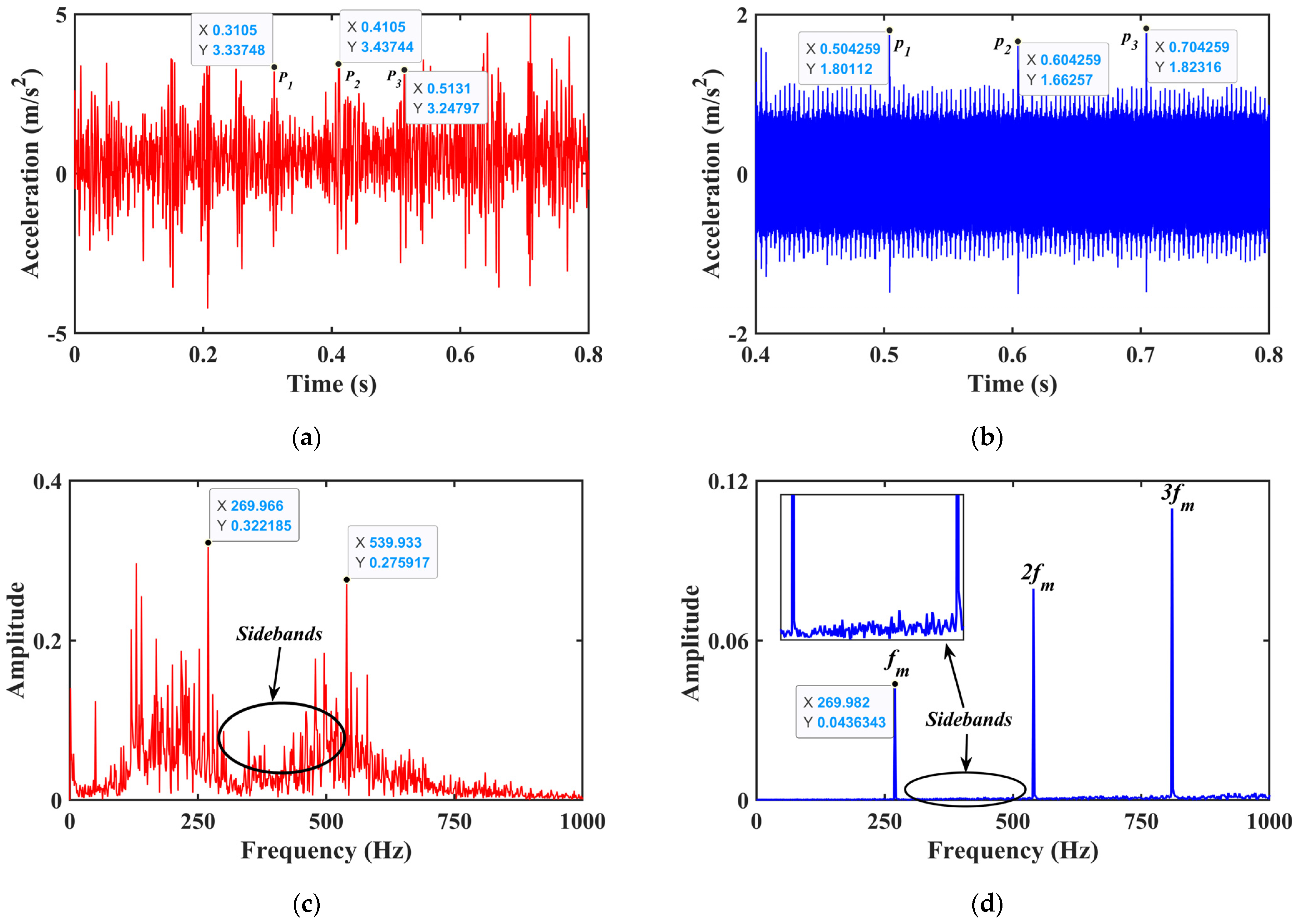
The comparison between the experimental and simulated signals in the time-domain and frequency-domain is presented in Figure 17. The gear vibration signal contains a lot of interference noise caused by the operation of mechanical equipment. The white noise of the ambient background appears in its full frequency band. In this paper, the moving average method is used to denoise the collected experimental signals. The rotational frequency of pinion and gear is fp (fp = np/60 = 10 Hz) and fg (fg = 8.7 Hz), respectively. The pinion’s meshing frequency and meshing are fm (fm = zp ∗ fp = 270 Hz) and Tp (Tp = 1/fm = 0.0037 s). The characteristic fault frequency is fs. It is the reciprocal of the failure period and can expressed as follows.
As shown in Table 3, there is little difference between the fault frequency calculated from the abscissa data of three points (P1, P2, P3) in Figure 17a and the data of the three points (P1, P2, P3) in Figure 17b.
Figure 17a,b show the time-domain experimental and simulated horizontal displacement signal. It can be observed that there is a certain difference in amplitude between the two cases, which is caused by experimental errors. Compared to experimental results, the simulated time-domain signal has a clear periodic impact to Zp ∗ Tp. The frequency response characteristic of the system under the two conditions is presented in Figure 17c,d. The frequency spectrum is mainly composed of gear mesh frequency and its harmonics. Peaks appear in the frequency spectrum at n ∗ fm, where n is a positive integer. However, the sideband structures can be seen clearly in both cases, as indicated by the arrow. The vibration spectrum of the spalled high-contact-ratio gear system is primarily characterized by the gear mesh frequency and its harmonics, and the sidebands induced by the modulation phenomenon. The results of simulated signal agree with that of experimental signals, which shows the reliability of the dynamic model proposed in this paper.
6. Conclusions
A novel approach for calculating the meshing stiffness of gear with tooth spalling defect is proposed. Simultaneously, a gear dynamic model is developed incorporating the time-varying mesh stiffness, fractal backlash and time-varying friction. The bifurcation characteristic of the gear system is acquired through the gear dynamic model. The vibration signatures of the gear system obtained experimentally are used to validate the dynamic model. Significant contributions of the study are summarized as follows:
- (1)
- The system’s motion with ellipsoid tooth spalling fault exhibits rich bifurcation and chaotic characteristics under the influence of excitation frequency and gear backlash. The system presents diverse motion states, including single periodic motion, multi-periodic motion, quasi-periodic motion, and chaotic motion. There are three typical routes to chaos in the response, i.e., crisis to chaos, quasi-period to chaos, and period-doubling bifurcation to chaos.
- (2)
- The frequency spectrum of the gear system with localized spalling fault is mainly composed of the meshing frequency and its harmonic components. The fault frequency appears in the form of sidebands in the spectrum at low speed. The tooth spalling fault could lead to the periodic impulses in the time-domain waveform.
Author Contributions
Z.C. (Writing—original draft: Lead); K.H. (Project administration: Lead); Y.X., (Data processing: Lead); M.S. (Software: Lead). All authors have read and agreed to the published version of the manuscript.
Funding
This study was supported by the National Natural Science Foundation of China (51775156), Natural Science Foundation of Anhui Province of China (1908085QE228), Key Research and Development Project of Anhui Province (202004h07020013), the Fundamental Research Funds for the Central Universities of China (PA2020GDSK0091), and the Horizontal Cooperation Project (0045022007).
Institutional Review Board Statement
Not applicable.
Informed Consent Statement
Not applicable.
Data Availability Statement
The data that support the findings of this study are available from the corresponding author upon reasonable request.
Conflicts of Interest
The authors state that they have no conflicting interest.
References
- Wang, Y.; Dou, D.; Wang, J. Comparison on torsional mesh stiffness and contact ratio of involute internal gear and high contact ratio internal gear. Proc. Inst. Mech. Eng. Part C J. Mech. Eng. Sci. 2020, 234, 1423–1437. [Google Scholar] [CrossRef]
- Huang, K.; Xiong, Y.; Wang, T.; Chen, Q. Research on the dynamic response of high-contact-ratio spur gears influenced by surface roughness under EHL condition. Appl. Surf. Sci. 2017, 392, 8–18. [Google Scholar] [CrossRef]
- Huang, K.; Yi, Y.; Xiong, Y.; Cheng, Z.; Chen, H. Nonlinear dynamics analysis of high contact ratio gears system with multiple clearances. J. Braz. Soc. Mech. Sci. Eng. 2020, 42, 98. [Google Scholar] [CrossRef]
- Wang, J.; Howard, I. Finite element analysis of high contact ratio spur gears in mesh. J. Tribol. 2005, 127, 469–483. [Google Scholar] [CrossRef]
- Zhan, J.; Fard, M.; Jazar, R. A CAD-FEM-QSA integration technique for determining the time-varying meshing stiffness of gear pairs. Measurement 2017, 100, 139–149. [Google Scholar] [CrossRef]
- Liang, X.; Zhang, H.; Zuo, M.J.; Qin, Y. Three new models for evaluation of standard involute spur gear mesh stiffness. Mech. Syst. Signal Process. 2018, 101, 424–434. [Google Scholar] [CrossRef]
- Sun, Y.; Ma, H.; Huangfu, Y.; Chen, K.; Che, L.; Wen, B. A revised time-varying mesh stiffness model of spur gear pairs with tooth modifications. Mech. Mach. Theory 2018, 129, 261–278. [Google Scholar] [CrossRef]
- Chaari, F.; Baccar, W.; Abbes, M.S.; Haddar, M. Effect of spalling or tooth breakage on gear mesh stiffness and dynamic response of a one-stage spur gear transmission. Eur. J. Mech. A Solids 2008, 27, 691–705. [Google Scholar] [CrossRef]
- Jiang, H.; Shao, Y.; Mechefske, C.K. Dynamic characteristics of helical gears under sliding friction with spalling defect. Eng. Fail. Anal. 2014, 39, 92–107. [Google Scholar] [CrossRef]
- Han, L.; Qi, H. Influences of tooth spalling or local breakage on time-varying mesh stiffness of helical gears. Eng. Fail. Anal. 2017, 79, 75–88. [Google Scholar] [CrossRef]
- Luo, W.; Qiao, B.; Shen, Z.; Yang, Z.; Chen, X. Time-varying mesh stiffness calculation of a planetary gear set with the spalling defect under sliding friction. Meccanica 2020, 55, 245–260. [Google Scholar] [CrossRef]
- Meng, Z.; Shi, G.; Wang, F. Vibration response and fault characteristics analysis of gear based on time-varying mesh stiffness. Mech. Mach. Theory 2020, 148, 103786. [Google Scholar] [CrossRef]
- Ma, H.; Li, Z.; Feng, M.; Feng, R.; Wen, B. Time-varying mesh stiffness calculation of spur gears with spalling defect. Eng. Fail. Anal. 2016, 66, 166–176. [Google Scholar] [CrossRef]
- Saxena, A.; Parey, A.; Chouksey, M. Time varying mesh stiffness calculation of spur gear pair considering sliding friction and spalling defects. Eng. Fail. Anal. 2016, 70, 200–211. [Google Scholar] [CrossRef]
- Yoshida, A.; Ohue, Y.; Ishikawa, H. Diagnosis of tooth surface failure by wavelet transform of dynamic characteristics. Tribol. Int. 2000, 33, 273–279. [Google Scholar] [CrossRef]
- Jia, S.; Howard, I. Comparison of localised spalling and crack damage from dynamic modelling of spur gear vibrations. Mech. Syst. Signal Process. 2006, 20, 332–349. [Google Scholar] [CrossRef]
- Ma, R.; Chen, Y.; Cao, Q. Research on dynamics and fault mechanism of spur gear pair with spalling defect. J. Sound Vib. 2012, 331, 2097–2109. [Google Scholar] [CrossRef]
- Dadon, I.; Koren, N.; Klein, R.; Lipsett, M.G.; Bortman, J. Impact of gear tooth surface quality on detection of local faults. Eng. Fail. Anal. 2020, 108, 104291. [Google Scholar] [CrossRef]
- Rui, M.; Chen, Y. Research on the dynamic mechanism of the gear system with local crack and spalling failure. Eng. Fail. Anal. 2012, 26, 12–20. [Google Scholar]
- Yu, W.; Mechefske, C.K.; Timusk, M. A new dynamic model of a cylindrical gear pair with localized spalling defects. Nonlinear Dyn. 2017, 2018, 2077–2095. [Google Scholar] [CrossRef]
- Chen, K.; Ma, H.; Che, L.; Li, Z.; Wen, B. Comparison of meshing characteristics of helical gears with spalling fault using analytical and finite-element methods. Mech. Syst. Signal Process. 2019, 121, 279–298. [Google Scholar] [CrossRef]
- Huangfu, Y.; Chen, K.; Ma, H.; Li, X.; Han, H.; Zhao, Z. Meshing and dynamic characteristics analysis of spalled gear systems: A theoretical and experimental study. Mech. Syst. Signal Process. 2020, 139, 106640. [Google Scholar] [CrossRef]
- Luo, W.; Qiao, B.; Shen, Z.; Yang, Z.; Cao, H.; Chen, X. Investigation on the influence of spalling defects on the dynamic performance of planetary gear sets with sliding friction. Tribol. Int. 2021, 154, 106639. [Google Scholar] [CrossRef]
- Shi, L.; Wen, J.; Pan, B.; Xiang, Y.; Zhang, Q.; Lin, C. Dynamic Characteristics of a Gear System with Double-Teeth Spalling Fault and Its Fault Feature Analysis. Appl. Sci. 2020, 10, 7058. [Google Scholar] [CrossRef]
- Ma, R.; Chen, Y. Bifurcation of multi-freedom gear system with spalling defect. Appl. Math. Mech. 2013, 34, 475–488. [Google Scholar] [CrossRef]
- Wu, J. Root Transition Curve and Root Stress; National Defense Industry Press: Arlington, VA, USA, 1989. [Google Scholar]
- Yang, L.; Baddour, N.; Ming, L. Dynamical modeling and experimental validation for tooth pitting and spalling in spur gears. Mech. Syst. Signal Process. 2018, 119, 155–181. [Google Scholar]
- Chen, Z.; Zhou, Z.; Zhai, W.; Wang, K. Improved analytical calculation model of spur gear mesh excitations with tooth profile deviations. Mech. Mach. Theory 2020, 149, 103838. [Google Scholar] [CrossRef]
- Chen, Q.; Wang, Y.; Tian, W.; Wu, Y.; Chen, Y. An improved nonlinear dynamic model of gear pair with tooth surface microscopic features. Nonlinear Dyn. 2019, 96, 1615–1634. [Google Scholar] [CrossRef]
- Chen, Q.; Zhou, J.; Khushnood, A.; Wu, Y.; Zhang, Y. Modelling and nonlinear dynamic behavior of a geared rotor-bearing system using tooth surface microscopic features based on fractal theory. AIP Adv. 2019, 9, 015201. [Google Scholar] [CrossRef] [Green Version]
- Xu, H. Development of a Generalized Mechanical Efficiency Prediction Methodology for Gear Pairs; The Ohio State University: Columbus, OH, USA, 2005. [Google Scholar]
- Yi, Y.; Huang, K.; Xiong, Y.; Sang, M. Nonlinear dynamic modelling and analysis for a spur gear system with time-varying pressure angle and gear backlash. Mech. Syst. Signal Process. 2019, 132, 18–34. [Google Scholar] [CrossRef]
Figure 1.
Rack-type cutting tool profile.
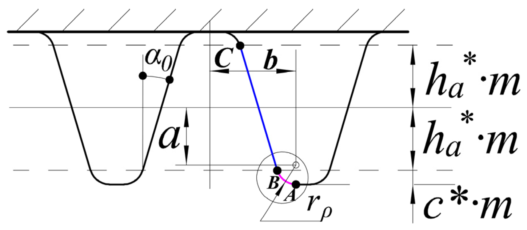
Figure 2.
Tooth profile curve diagram.
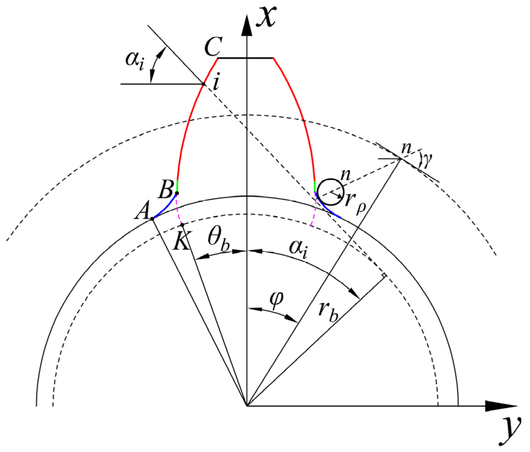
Figure 3.
The ellipsoid tooth spall on the pinion.
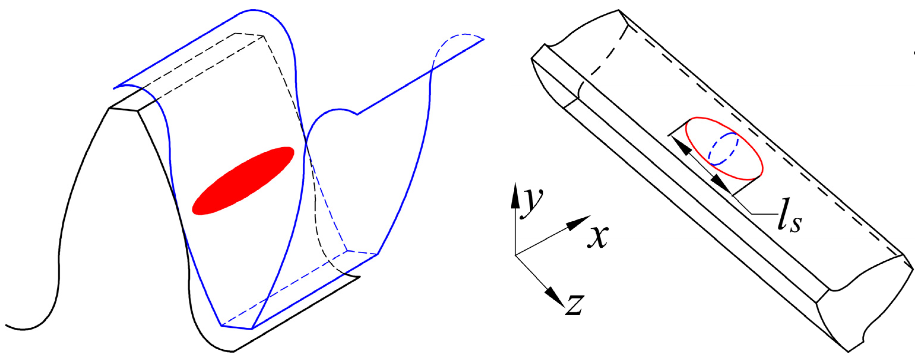
Figure 4.
A cross-sectional view of the ellipsoid tooth spall.
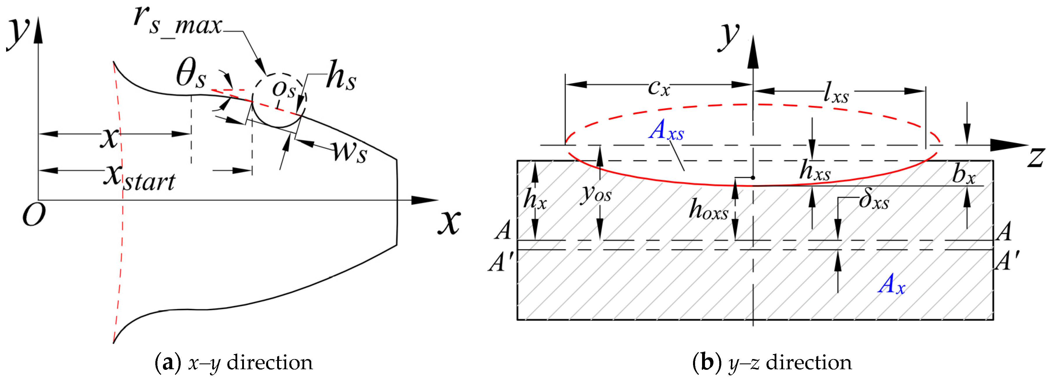
Figure 5.
Gear profile.
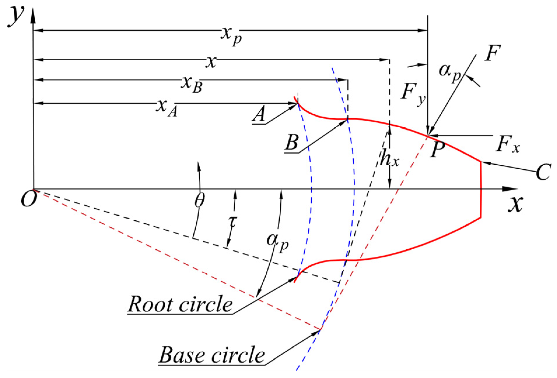
Figure 6.
Time-varying mesh stiffness.
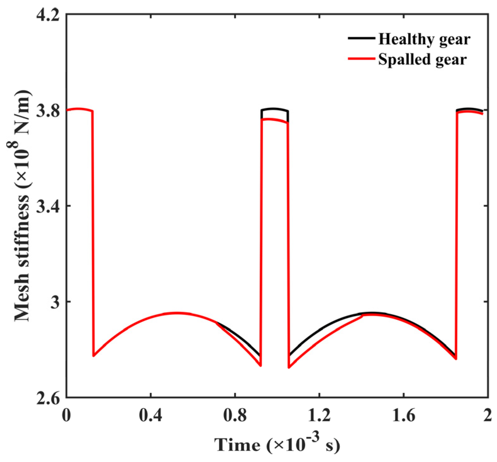
Figure 7.
Gear dynamic model.
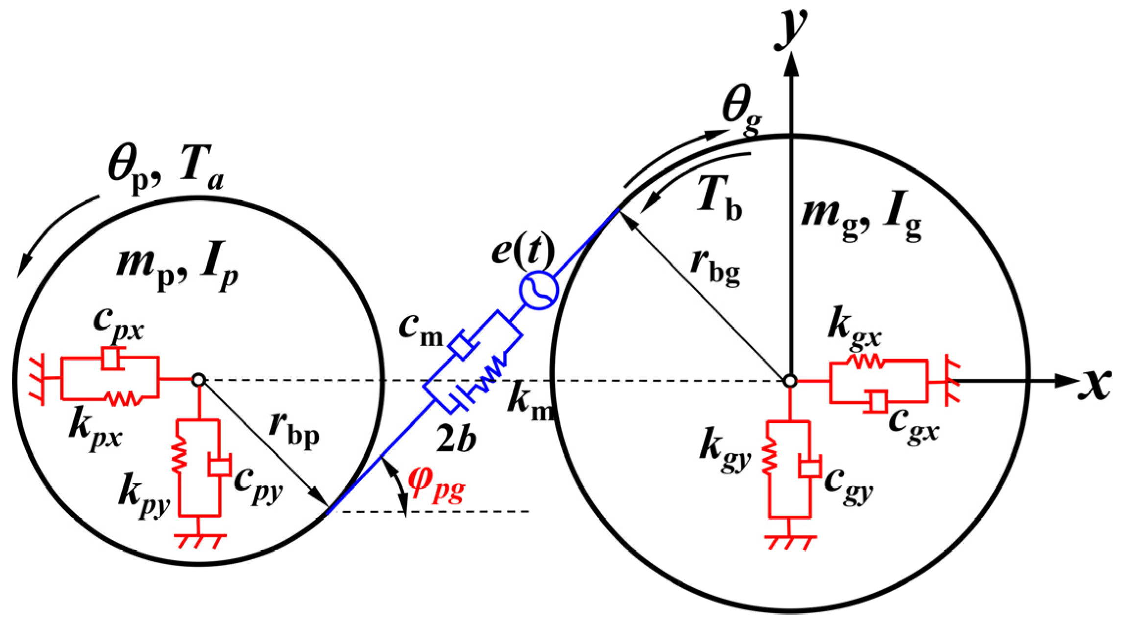
Figure 8.
Geometrical relationship of gear pair.
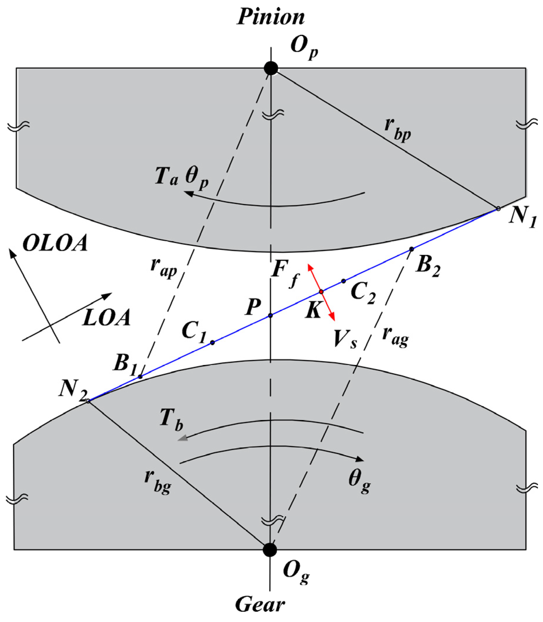
Figure 9.
Time−varying friction coefficient.

Figure 10.
Bifurcation diagram under different excitation frequency.
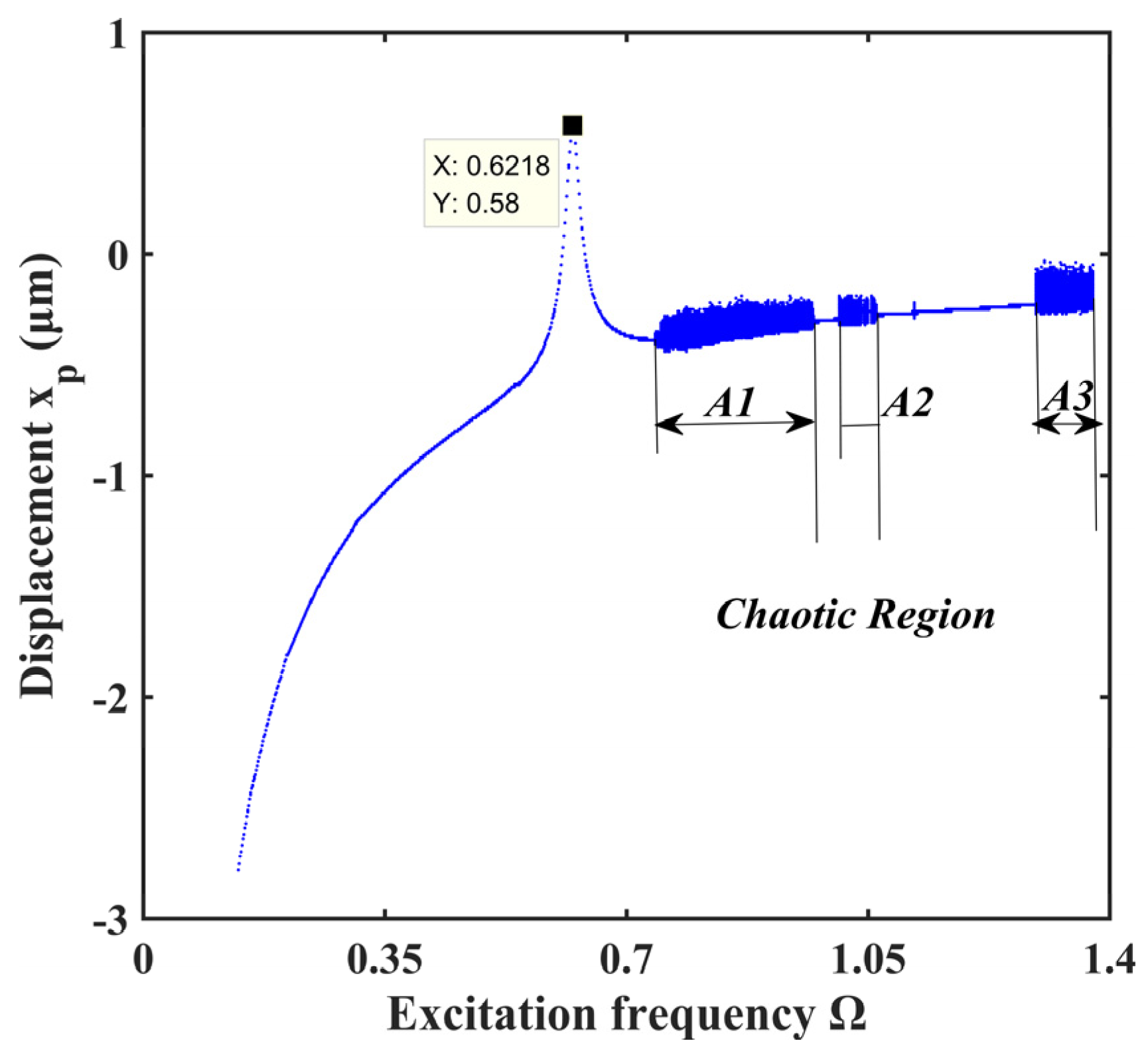
Figure 11.
Three−dimensional frequency spectrum under different excitation.
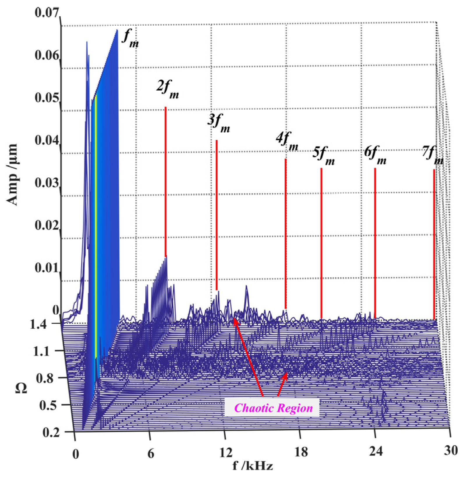
Figure 12.
Evolution process of system response for Ω ∈ [0.5, 1.3].
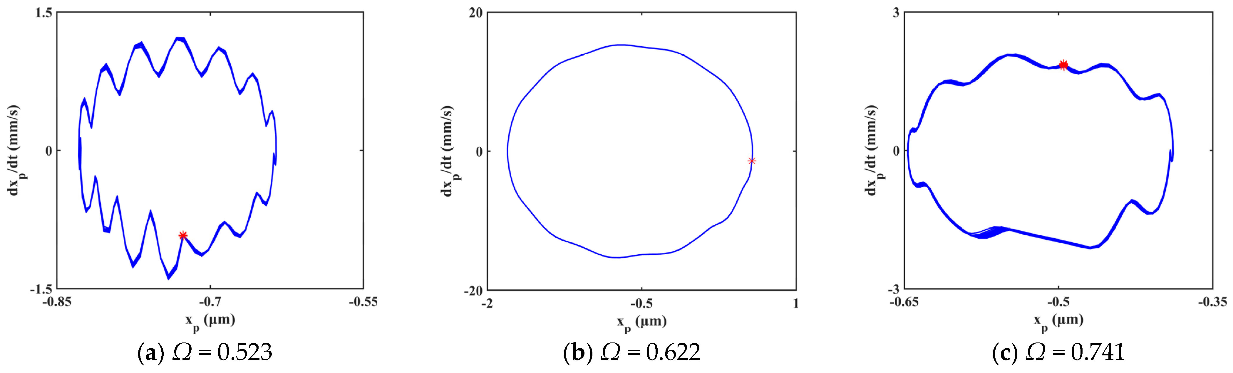
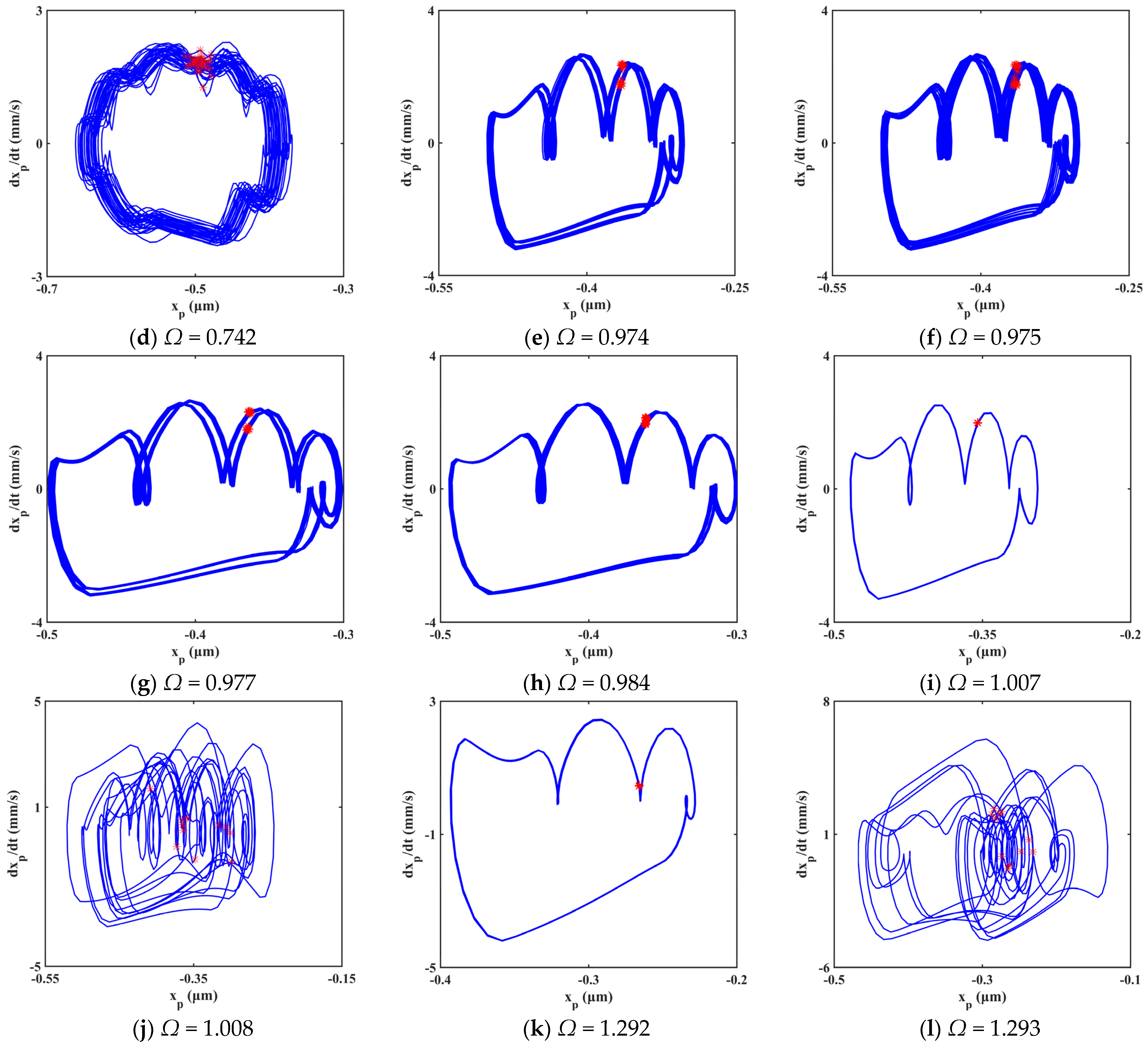
Figure 13.
Bifurcation diagram under different gear backlash.
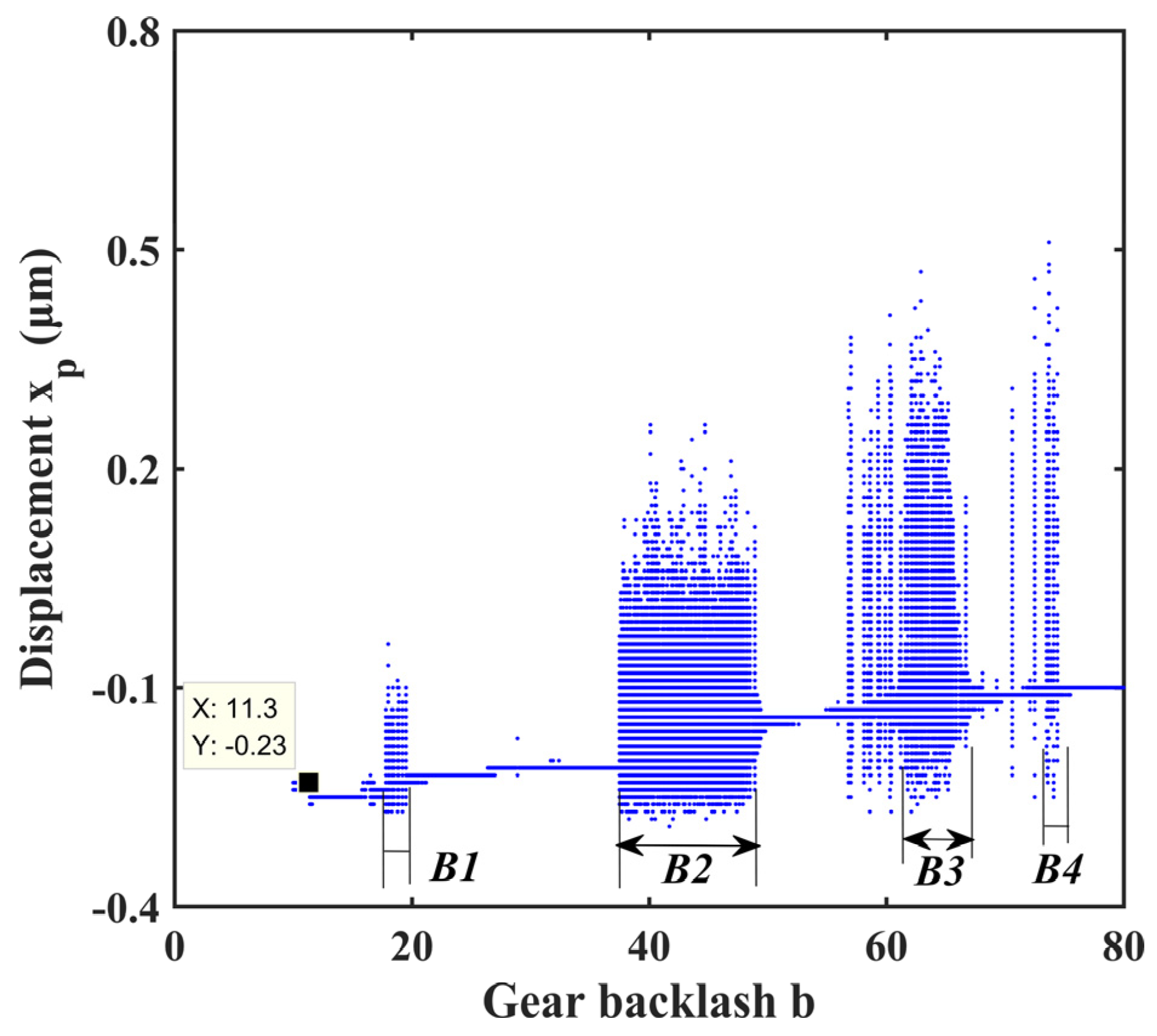
Figure 14.
Three-dimensional frequency spectrum under different gear backlash.
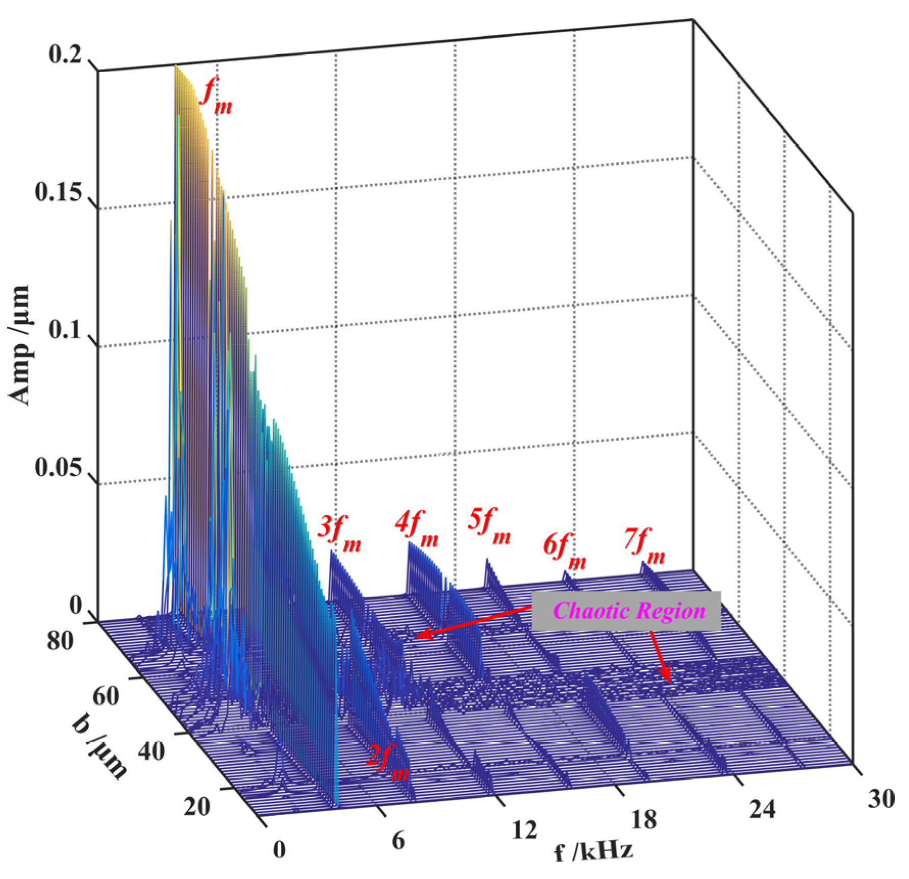
Figure 15.
Evolution process of system response at the range of b∈ [17, 75].
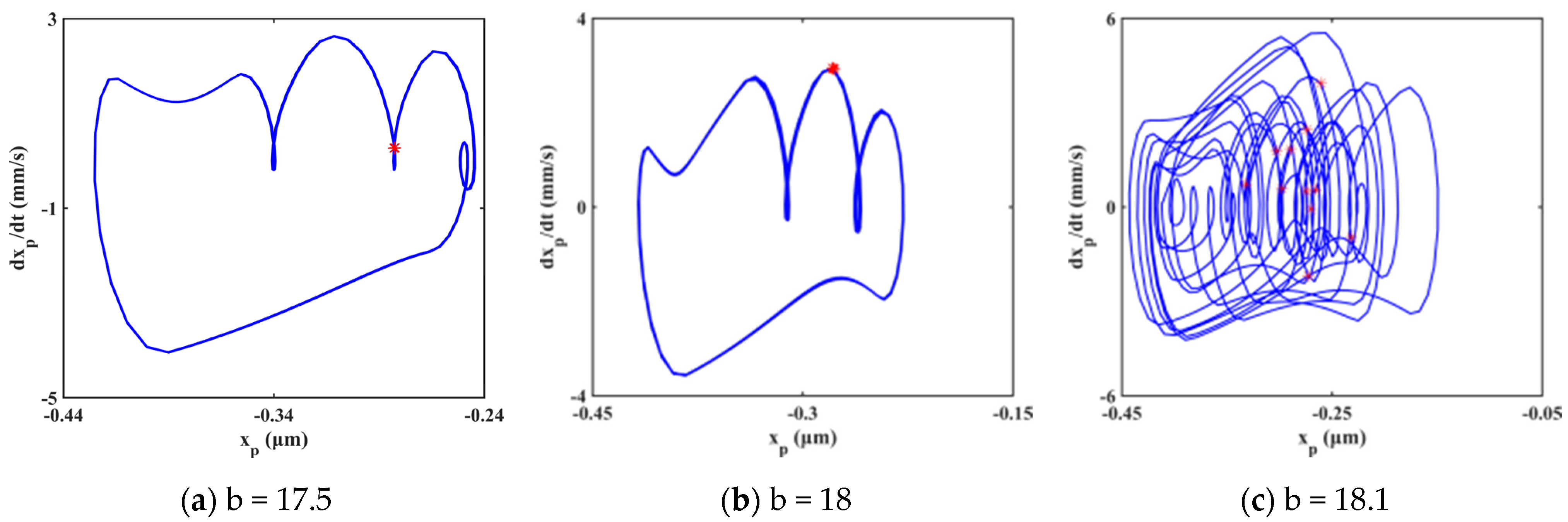
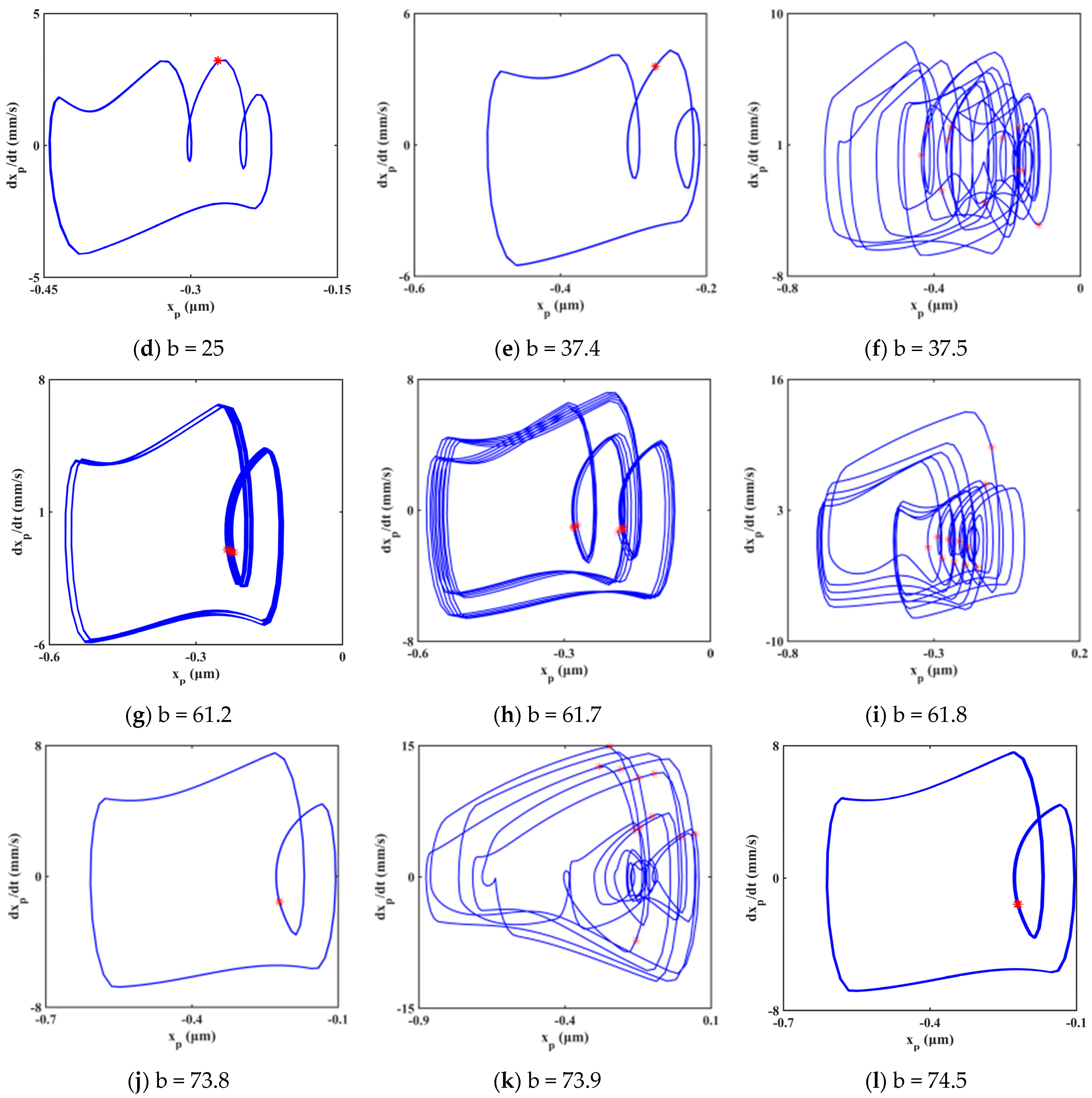
Figure 16.
Experimental setup.
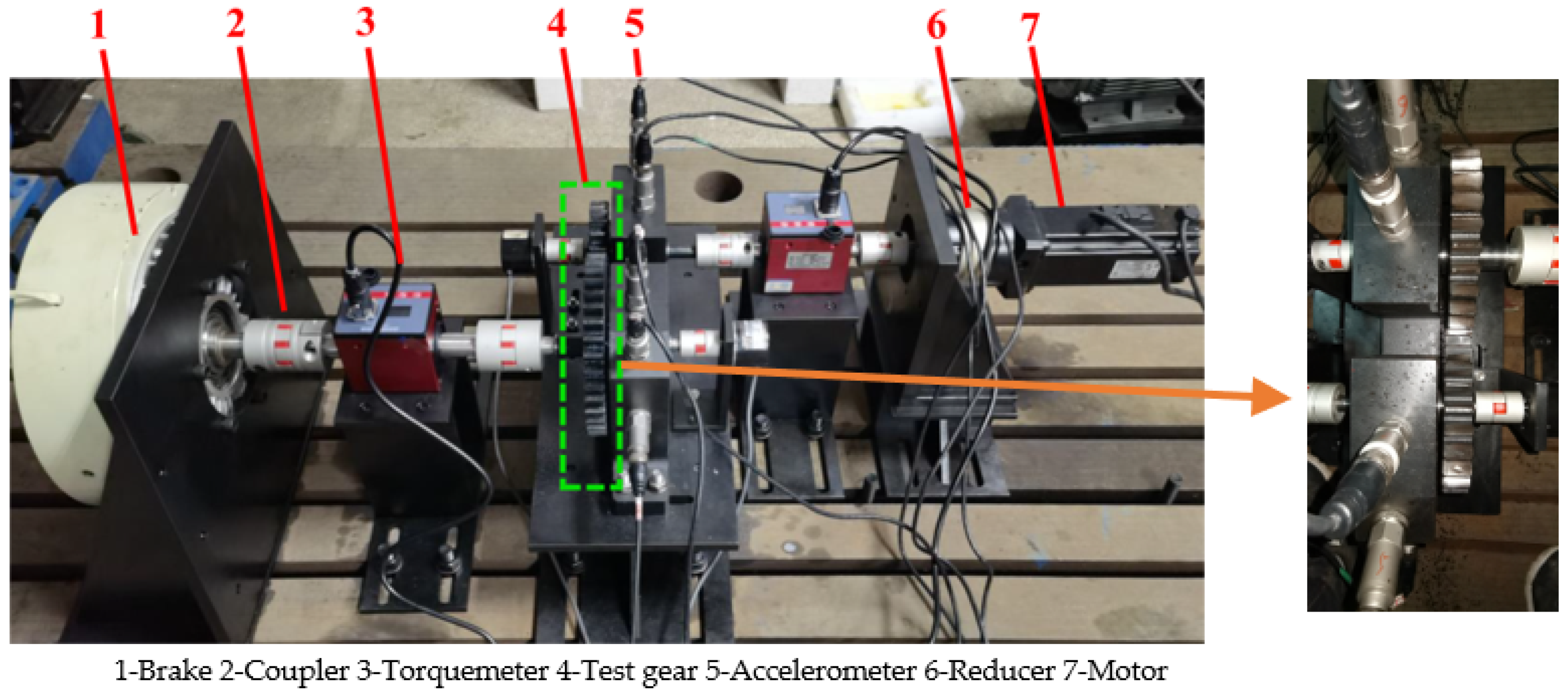
Figure 17.
Comparison between the experimental and simulated signals in horizontal direction. (a) Time−domain of experimental signal, (b) Time−domain of simulated signal, (c) Frequency spectrum of the experimental signal, (d) Frequency spectrum of the simulated signal.
Figure 17.
Comparison between the experimental and simulated signals in horizontal direction. (a) Time−domain of experimental signal, (b) Time−domain of simulated signal, (c) Frequency spectrum of the experimental signal, (d) Frequency spectrum of the simulated signal.

Table 1.
The ellipsoid tooth spall data.
| Case | ws (mm) | ls (mm) | hs (mm) | θs (°) | xstart (mm) |
|---|---|---|---|---|---|
| Healthy gear | 0 | 0 | 0 | 0 | 0 |
| Spall gear | 4 | 16 | 2 | 18 | 66 |
Table 2.
Main parameters of the high-contact-ratio gear.
| Parameters | Pinion/Gear | Parameters | Pinion/Gear |
|---|---|---|---|
| Tooth Number zp/zg | 27/31 | Designed contact ratio | 2.135 |
| Transverse modulus (mm) | 5 | Tooth width (mm) | 20 |
| Pressure angle (°) | 19 | Moments of inertia (kg·m2) Ip/Ig | 0.0051/0.0089 |
| Addendum coefficient | 1.32 | Mass (kg) mp/mg | 2.13/2.84 |
| Modification coefficient | 0 | Mesh damping ratio | 0.06 |
| Hub bore radius (mm) | 14 | Input power (kW) | 20 |
Table 3.
Fault frequency calculation.
| Fault Frequency (fs) | Simulation Results | Experimental Results | Error |
|---|---|---|---|
| 10 Hz | 10 Hz | 0% | |
| 10 Hz | 9.75 Hz | 2.5% |
Publisher’s Note: MDPI stays neutral with regard to jurisdictional claims in published maps and institutional affiliations. |
© 2022 by the authors. Licensee MDPI, Basel, Switzerland. This article is an open access article distributed under the terms and conditions of the Creative Commons Attribution (CC BY) license (https://creativecommons.org/licenses/by/4.0/).
Share and Cite
MDPI and ACS Style
Cheng, Z.; Huang, K.; Xiong, Y.; Sang, M. Dynamic Analysis of a High-Contact-Ratio Spur Gear System with Localized Spalling and Experimental Validation. Machines 2022, 10, 154. https://doi.org/10.3390/machines10020154
AMA Style
Cheng Z, Huang K, Xiong Y, Sang M. Dynamic Analysis of a High-Contact-Ratio Spur Gear System with Localized Spalling and Experimental Validation. Machines. 2022; 10(2):154. https://doi.org/10.3390/machines10020154
Chicago/Turabian StyleCheng, Zhenbang, Kang Huang, Yangshou Xiong, and Meng Sang. 2022. "Dynamic Analysis of a High-Contact-Ratio Spur Gear System with Localized Spalling and Experimental Validation" Machines 10, no. 2: 154. https://doi.org/10.3390/machines10020154
Note that from the first issue of 2016, this journal uses article numbers instead of page numbers. See further details here.