Article

A Hybrid Mechanism-Based Robot for End-Traction Lower Limb Rehabilitation: Design, Analysis and Experimental Evaluation

1
Parallel Robot and Mechatronic System Laboratory of Hebei Province, Yanshan University, Qinhuangdao 066004, China
2
School of Mechanical Engineering, Hebei University of Technology, Tianjin 300130, China
3
School of Control Science and Technology, Shandong University, Jinan 250061, China
*
Authors to whom correspondence should be addressed.
Machines 2022, 10(2), 99; https://doi.org/10.3390/machines10020099
Submission received: 9 December 2021 / Revised: 17 January 2022 / Accepted: 25 January 2022 / Published: 27 January 2022
(This article belongs to the Special Issue Smart Machines: Applications and Advances in Human Motion Analysis)

Abstract

:
Conventional lower-limb rehabilitation robots cannot provide in-time rehabilitation training for stroke patients in the acute stage due to their large size and mass as well as their complex wearing process. Aiming to solve the problems, first, a novel hybrid end-traction lower-limb rehabilitation robot (HE-LRR) was designed as the lower-limb rehabilitation requirement of patients in the acute stage, in this paper. The usage of (2-UPS + U)&(R + RPS)&(2-RR) hybrid mechanism and a mirror motion actuator had the advantages of compact structure, large working space and short wearing time to the HE-LRR. Then, the mobility of the HE-LRR was calculated and the motion property was analyzed based on screw theory. Meanwhile, the trajectory planning of the HE-LRR was carried out based on MOTOmed® motion training. Finally, the motion capture and surface electromyography (sEMG) signal acquisition experiments in the MOTOmed motion training were performed. The foot trajectory experimental effect and the lower-limb muscle groups activation rules were studied ulteriorly. The experimental results showed that the HE-LRR achieved good kinematic accuracy and lower limb muscle groups training effect, illustrating that the HE-LRR possessed good application prospects for the lower-limb rehabilitation of patients in the acute stage. This research could also provide a theoretical basis for improving the standardization and compliance of lower-limb robot rehabilitation training.

1. Introduction

Limb motion function recovery is an urgent problem faced by stroke patients in the rehabilitation process [1,2]. According to clinical trials, specific forms of exercise can promote the self-repair and functional reorganization of a patient’s nervous system and realize the recovery of limb motor function [3,4]. For the lower-limb rehabilitation process, continuous passive motion (CPM) and straight leg raise (SLR) are effective training methods in the early bedridden period when patients are too weak to support their weight [5,6,7]. When the activity ability is recovered to a certain extent, it is necessary to use MOTOmed exercise training with greater exercise intensity [8]. According to the methods and the stages of the rehabilitation treatment, various types of instruments should be prepared; this may be expensive for the patients. Therefore, it is of great significance to develop a lower-limb rehabilitation robot that can cover the entire course of the disease, which can assist the patient to receive early rehabilitation treatment, prevent complications [9], improve the rehabilitation effect of patients, reduce the burden on doctors, and optimize the multi-scenario application of rehabilitation equipment [10,11].
The fundamental issue of developing the lower-limb rehabilitation robot locates in the design of the mechanism. The serial mechanism has the advantages of simple structure and large working space, while the parallel mechanism has better rigidity and compact structure. Existing lower-limb rehabilitation robots mainly include the serial-type and the parallel-type [12,13,14]. On one hand, in the research field of serial lower-limb rehabilitation robots, Hocoma Company developed a suspended standing lower-limb rehabilitation robot Lokomat [15]. Its mechanical legs could assist patients to simulate the walking gait of healthy persons and restore the control ability of the nervous system for the walking process. However, it was only suitable for rehabilitation training in the middle or late period when the patient had a certain walking ability, and could only perform rehabilitation exercises in the sagittal plane. The University of Twente in the Netherlands developed a similar rehabilitation robot Lopes [16]. The hip joint of each leg had two degrees of freedom, and the knee joint had one degree of freedom. It could provide gait training for the patient. Nevertheless, the excessive demands for space of Lopes meant that the robot were not conducive to multi-scenario applications such as hospitals, health care centers, and homes. The Swortec Company developed a sitting and lying rehabilitation robot MotionMaker [17]. The robot had two 3-DOF mechanical legs in series. It could adopt different training modes in the patient’s different rehabilitation stages, and the patient could sit on a chair for rehabilitation training. However, the mobility of the robot was limited to the sagittal plane, which led to limitations on the rehabilitation training of the hip and ankle joints.
On the other hand, in the research field of parallel lower-limb rehabilitation robots, the Rutgers Ankle developed by Rutgers University was an ankle joint rehabilitation robot based on Stewart mechanism [18], which could achieve human gait training through the collaborative control of two platforms. Limited to the small working space of the parallel mechanism, the robot could not guarantee the ankle rehabilitation effect. King’s College London proposed a 3-UPS/U parallel mechanism [19], which could realize ankle rehabilitation training with two degrees of freedom of rotation, as well as lower-limb rehabilitation training through the coupling relationship of the human body; however, the problem of small working space and poor training effect existed. South Korea developed a planar cable-driven parallel rehabilitation robot [20], which utilized ropes to drive the lower limbs of patient to complete closed gait trajectory training. It could achieve the rehabilitation training in a larger space, but its working space, which was within a sagittal plane, caused by the layout of the drive mechanism, limited its further application.
Although many types of robots have been developed in previous research, most of them are applicable to mid-to-late rehabilitation training, and their size and motion form are limited, none of them could achieve full cycle coverage during rehabilitation training, flexible movements of lower limbs with multiple degrees of freedom, or multi-scene convenient application (hospitals, health centers, home, etc.) [21,22,23].
To satisfy the acute rehabilitation training needs of stroke patients, this research designed a 5-DOF hybrid end-traction lower-limb rehabilitation robot suitable for double-postures training (sitting posture/lying posture) and full cycle training. Utilizing the (2-UPS + U)&(R + RPS)&(2-RR) hybrid mechanism, where R, P, U and S represent revolute, prismatic, universal and spherical joints, respectively, realized the innovative design of lower-limb rehabilitation robots with multiple degrees of freedom, large working space and compact structure. On the above basis, the mirror rotation mechanism was designed by introducing a 2-RR mechanism into the hybrid mechanism, which could realize the mirror movement of the lower limbs and improve the rehabilitation effect.
The main highlights of this paper are as follows.
(1) A hybrid end-traction low limb rehabilitation robot with (2-UPS + U)&(R + RPS)&(2-RR) configuration was designed to achieve the double-posture training (sitting posture/lying posture) during the acute stage.
(2) By combining the screw theory and the kinematic screw multiset method, the mobility calculation and the mobility property analysis of the hybrid mechanism were accomplished.
(3) The motion of the main low limb muscle groups during the MOTOmed exercise training was tested to guide the targeted rehabilitation training and improve the compliance of robots.
In this paper, we firstly introduced the structure of a hybrid end-traction lower-limb rehabilitation robot (HE-LRR) and analyzed the mobility property of the robot. Secondly, the inverse kinematics of the HE-LRR were established and the trajectory planning for the rehabilitation robot was carried out based on MOTOmed exercise training. Finally, the motion capture and sEMG signal acquisition experiments were conducted to verify the motion performance of the HE-LRR.

2. Materials and Methods

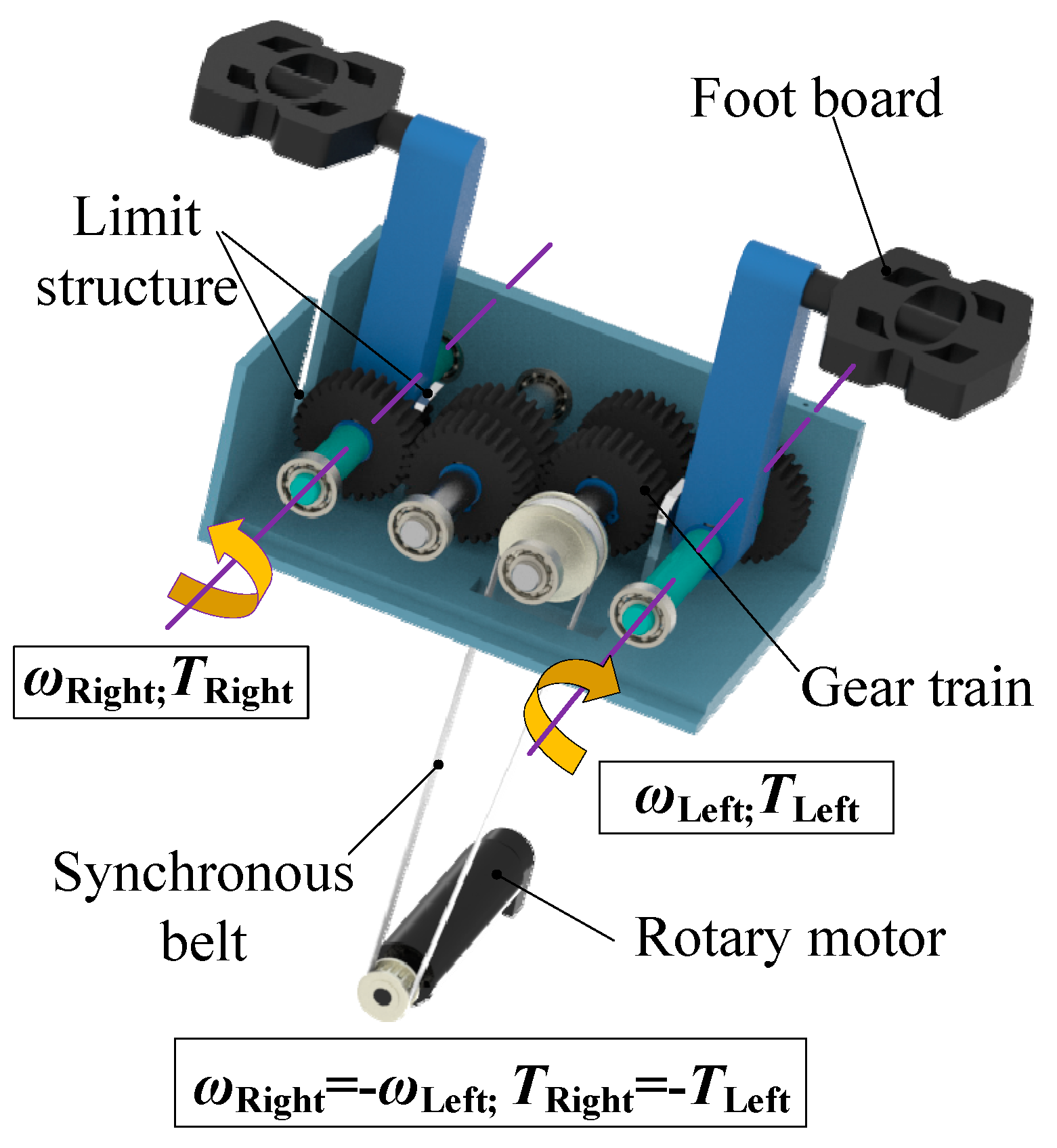
2.1. Configuration Design

The lower limb movement of human body mainly comprises walking in the sagittal plane, stepping in the coronal plane, and turning around the longitudinal axis of the human body. The HE-LRR was designed based on ergonomics, which mainly included a mainframe, (2-UPS + U)&(R + RPS) hybrid mechanism and (2-RR) mirror motion actuator. It is convenient to wear and operate in various rehabilitation training occasions, especially when the patient is in the acute stage and with a narrow space. The virtual prototype and schematic diagram of the HE-LRR is shown in Figure 1. People can sit or lie on the opposite side of the machine with their feet connected to the machine, and then they can achieve rehabilitation training driven by the HE-LRR.
According to the simplified rotation characteristic of the hip joint that two rotation axes are orthogonal, the parallel part of the HE-LRR was designed as a 2-UPS + U mechanism, which includes two UPS branches (A1B1 and A2B2) and one U branch chain OB. The parallel pair is driven by the linear actuator l01 and l02 to realize the rotation of the OD branch chain around the cross axis, to assist the lower limb to realize the sagittal and coronal rehabilitation training exercises. The knee joint is simplified as one rotation joint, and the rotation movement can be achieved by introducing the RPR branch chain C2C3 into the parallel part and taking the linear actuator l03 as driving unit. The coordinated motion of (2-UPS + U)&(R + RPS) mechanism can meet the rehabilitation training requirements of patients with multiple degrees of freedom. Compared with the rotary motor driving directly as a revolute joint, the usage of R + RPS mechanism can reduce the mass and inertia of the robot moving joint and improve the bearing capacity of it.
On this basis, one 2-RR synchronous mirror motion actuator was added on the end pedal of the robot, as shown in Figure 2. The two RR branches, F1E1 and F2E2, were driven by gears in the gearbox and foot boards to achieve the same angular velocity and torque, but the rotation direction was opposite, assisting the patient’s hip joint to carry out coronal rehabilitation training. Through end traction, the robot can not only be applied to sitting and lying posture rehabilitation training but can also meet the needs of opening and closing mirror training of the lower limbs and correcting the natural abduction and external rotation of the hip in patients with hemiplegia [24]. It is very beneficial to enrich the training form of patients in the bedridden stage.

2.2. Mobility Analysis

Firstly, the mobility of the hybrid mechanism is calculated separately by the parallel mechanism and the serial mechanism. For the (2-UPS + U) parallel mechanism, the mobility is calculated according to the modified Kutzbach–Grübler formula. The formula is as follows:
M = d ( n g 1 ) + i = 1 g f i + v η
where M is the mobility of a mechanism, d is the order of a mechanism, n is the number of links including frame, g is the number of kinematic pairs, fi is the freedom of the ith kinematic pair, v is the total number of the over-constraints of the mechanism and η is the number of local freedoms.
The UPS branch chain is a 6-DOF unconstrained branch chain. The order of the mechanism d = 6, the number of links n = 6, the number of kinematic pairs g = 7, the algebraic sum of the freedom of each kinematic pair i = 1 7 f i = 14 and the (2-UPS + U) parallel mechanism do not have over-constraints and local freedoms, so the mobility of the parallel mechanism is
M = 6 × ( 6 7 1 ) + 14 0 = 2
In addition, the mobility of the (2-RR) branches is 2; hence, the overall mobility of the robot mechanism is 5.
Then, the screw theory is utilized to analyze the mobility property of the robot mechanism. Let (X1, Y1, Z1), (X2, Y2, Z2), (X3, Y3, Z3), (X4, Y4, Z4) and (X5, Y5, Z5) be the coordinates of points D, C2, C3, E1 and F1, respectively. Then, the kinematic screw system of the (2-UPS + U)&(R + RPS) hybrid mechanism S 1 and the kinematic screw system of the 2-RR mechanism S 2 are as follows:
S 1 = { $ 1 = ( 100 ; 000 ) $ 2 = ( 010 ; 000 ) $ 3 = ( 000 ; 001 ) $ 4 = ( 100 ; 0 Z 1 0 ) $ 5 = ( 100 ; 0 Z 2 Y 2 ) $ 6 = ( 100 ; 0 Z 3 Y 3 ) ,   S 2 = { $ 1 = ( 100 ; Z 4 0 X 4 ) $ 2 = ( 010 ; 0 Z 5 Y 5 )
The bases of kinematic screw systems S 1 and S 2 can be utilized to construct the mechanism kinematic screw multiset S m . The multiple sets can contain repeated elements [25]. Therefore, S m can be expressed as:
S m = S 1 S 2
Since only five linearly independent screws are included in S m , a set of non-unique bases of mechanism kinematic screw system S m can be chosen as:
S m = { $ 1 = ( 100 ; 000 ) $ 2 = ( 010 ; 000 ) $ 3 = ( 000 ; 001 ) $ 4 = ( 100 ; 0 Z 1 0 ) $ 5 = ( 100 ; Z 4 0 X 4 )
The constrained screw system can be expressed as
$ 1 r = ( 000 ; 001 )
Therefore, the (2-UPS + U)&(R + RPS)&(2-RR) hybrid mechanism’s rotation around the Z-axis direction is restricted, and it can realize the rotation around the X-axis and the Y-axis as well as the translation along three pairwise orthogonal axes. The overall mobility can meet the needs of lower-limb rehabilitation robots for multi-degree-of-freedom and multi-posture training.

2.3. Inverse Kinematics

The robot inverse kinematics are the basis of robot trajectory planning. To carry out the trajectory planning of the HE-LRR, the inverse kinematics solution of the robot needs to be solved first [26,27]. The mechanism coordinate system is established as in Figure 3.
The origin of the fixed coordinate system O-XYZ is located at the intersection point of the two rotation axes of the universal joint. The X-axis coincides with the direction of OA2, the Y-axis coincides with the direction of OA1 and the direction of the Z-axis can be obtained by the right-hand rule. The origin of the kinetic coordinate system B-XBYBZB is at a certain fixed position of the OD rod. The XB axis is along the BB2 direction, and the YB axis is along the BB1 direction. The kinetic coordinate system D-XDYDZD is also established, where the XD axis is parallel to the rotary axis at point D, and the ZD axis is upward along the OD direction. The kinetic coordinate system F-XFYFZF is established, the XF axis is along the F1F2 direction and the ZF axis is upward along the DF direction. The process of solving the inverse kinematics of the HE-LRR is as follows.
First, the coupling relationship between the linear actuator lengths l01 and l02 of the parallel part is analyzed. The rotation of the moving platform around the base platform can be regarded as the kinetic coordinate system B-XBYBZB around the fixed coordinate system O-XYZ X-axis and Y-axis rotation, and the rotation matrix of the moving platform at this time is
R B O = R o t ( Y , β ) R o t ( X , α ) = [ cos β sin α sin β cos α sin β 0 cos α sin α sin β sin α cos β cos α cos β ]
The position vectors of A1, A2 and O in the fixed coordinate system {O-XYZ} are
{ m 1 = ( 0 a 1 0 ) T m 2 = ( a 2 0 0 ) T m 3 = ( 0 0 0 ) T
The position vectors of B1, B2 and B in the kinetic coordinate system {B-XBYBZB} are, respectively,
{ n 1 = ( 0 b 1 0 ) T n 2 = ( b 2 0 0 ) T n 3 = ( 0 0 0 ) T
Among them, a1 and a2 are the mechanical parameters of the base platform and b1 and b2 are the mechanical parameters of the moving platform.
Establish the position constraint equation of the parallel part in the fixed coordinate system {O-XYZ}
l O B + n i = m i + A i B i ( i = 1 , 2 )
where l O B = ( l O B cos α sin β l O B sin α l O B cos α cos β ) T .
Substituting mechanical parameters into Equation (10) and simplifying to get expressions of l01 and l02
{ l 01 = a 1 2 + b 1 2 + l O B 2 2 a 1 b 1 cos α + 2 l O B a 1 sin α l 02 = a 2 2 + b 2 2 + l O B 2 2 a 2 b 2 cos β 2 l O B a 2 cos α sin β
Next, analyze the relationship between parameters l03 and γ. According to the Cosine Theorem, we can get
cos C 2 D C 3 = b 3 2 + m 2 2 + m 1 2 + a 3 2 l 03 2 2 b 3 2 + m 2 2 m 1 2 + a 3 2
γ angle can be solved as following
γ = π arccos b 3 2 + m 2 2 + a 3 2 + m 1 2 l 03 2 2 b 3 2 + m 2 2 a 3 2 + m 1 2
Hence, l03 can be expressed as
l 03 = a 3 2 + b 3 2 + m 1 2 + m 2 2 + 2 m 1 2 + a 3 2 m 2 2 + b 3 2 cos ( γ + arctan b 3 m 2 + arctan a 3 m 1 )
where a3 is the length of CC3, b3 is the length of C1C2, m1 is the length of CD and m2 is the length of C1D.

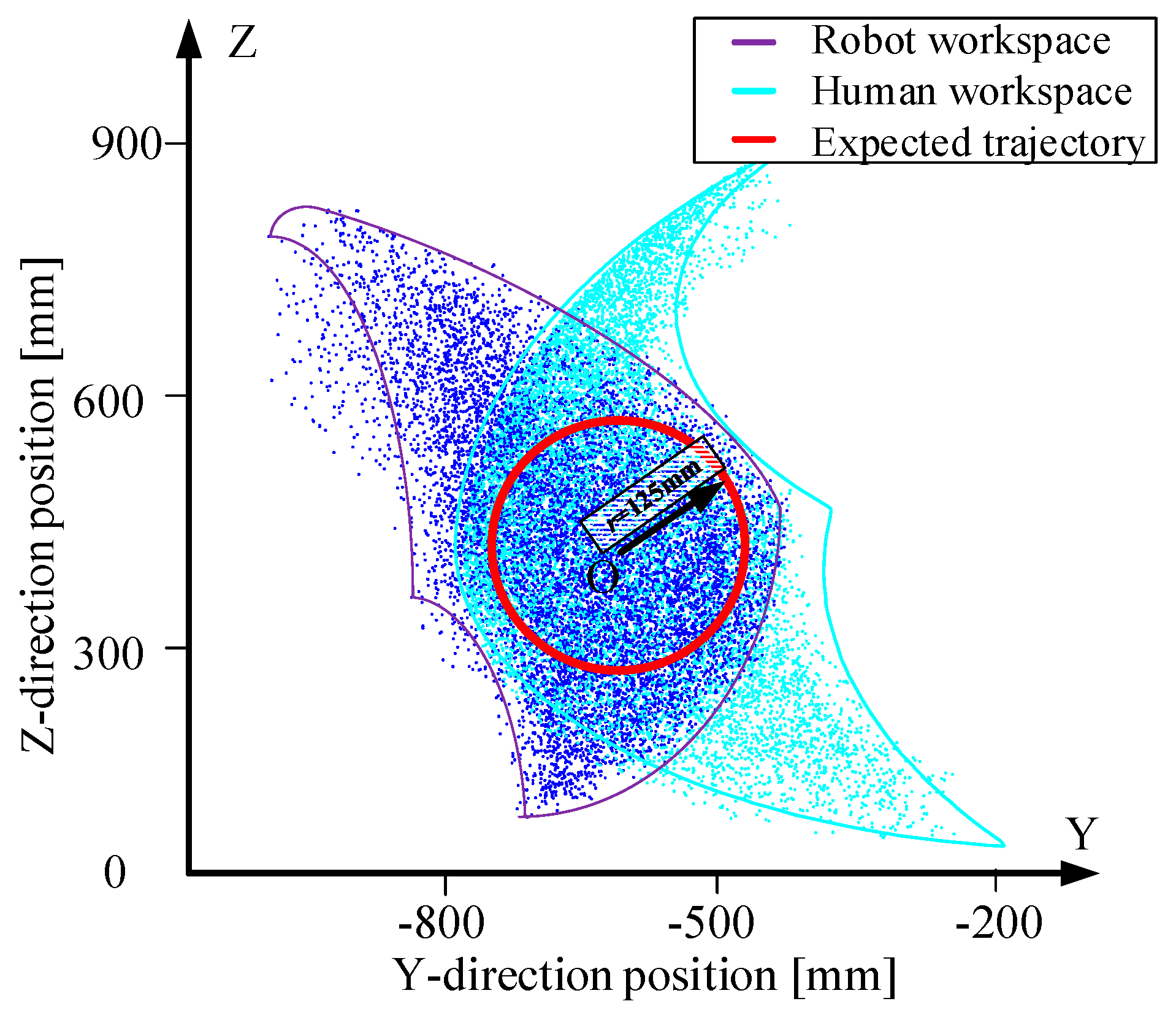
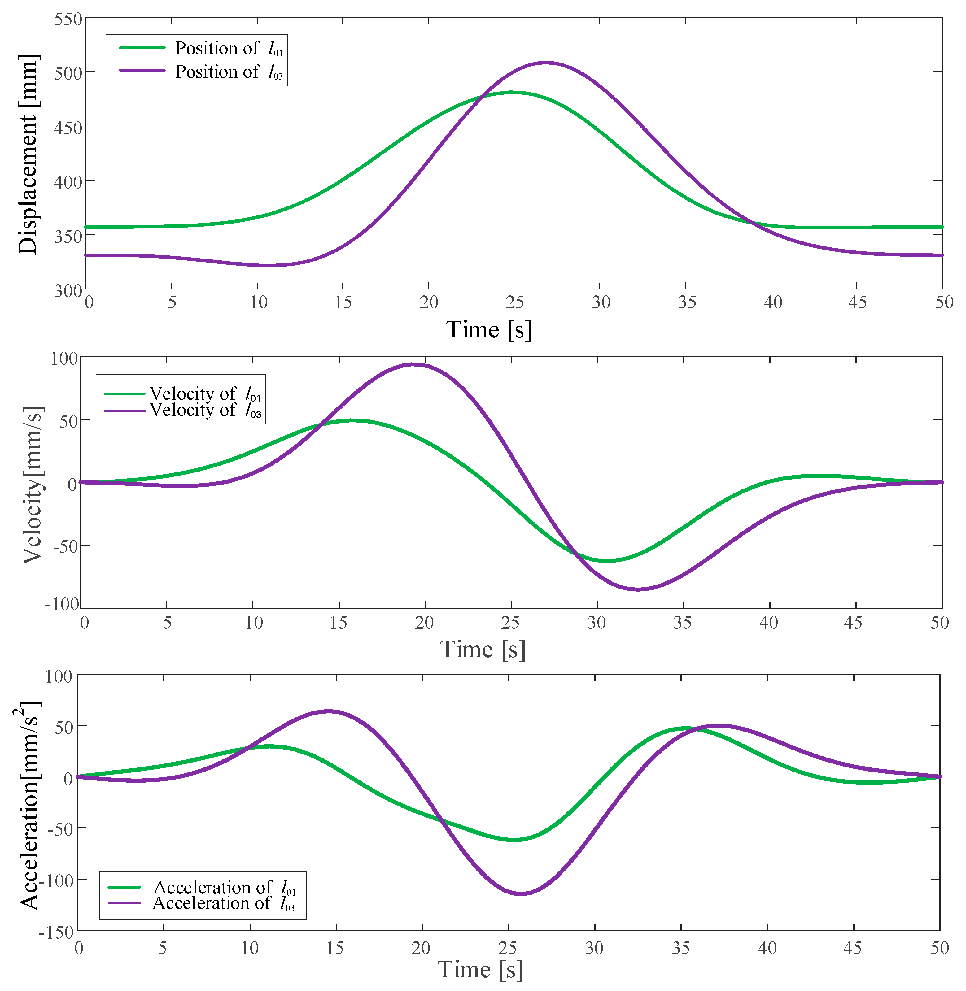
2.4. Trajectory Planning

MOTOmed exercise training is similar to bicycle exercise, and the human foot trajectory is a circle in space. This kind of exercise training is suitable for patients in acute stage and has achieved good clinical treatment effects in lower-limb rehabilitation training [28,29]. In this section, the typical MOTOmed exercise training is taken as an example to carry out the trajectory planning of the HE-LRR. By referring to human dimensions of Chinese adults, we choose the 95% quantile statistical data of human lower limbs as the basis of human workspace calculation. Moreover, in order to achieve the matching of robot workspace and human lower limb workspace, we iterated and optimized the size of robot branch chain. The final working spaces of the lower limb and the HE-LRR in the sagittal plane are shown in Figure 4. The purple area represents the working space of the lower limbs, and the blue area represents the working space of the HE-LRR. The red circle represents the expected MOTOmed training trajectory. The coordinates of the circle center are set as (y0, z0) = (−670,470), the radius of the circle r = 125 mm, and the prescribed exercise time is 50 s per cycle.
Define the center angular displacement function of the robot end point as a fifth-degree polynomial:
θ ( t ) = a 0 + a 1 t + a 2 t 2 + a 3 t 3 + a 4 t 4 + a 5 t 5
Let the starting angular displacement be 360° and the ending angular displacement be 0°. At the same time, in order to ensure the continuity of the center angular velocity and the smooth movement of the robot end point, thereby improving the training comfort, the set constraint conditions of the center angular displacement function are as follows:
{ θ ( 0 ) = 2 π θ ( t f ) = 0 θ ˙ ( 0 ) = 0 θ ˙ ( t f ) = 0 θ ¨ ( 0 ) = 0 θ ¨ ( t f ) = 0
According to the above constraint conditions, the fifth-degree polynomial of the angular displacement of the MOTOmed training can be obtained as:
θ ( t ) = 6.2823 0.0628 t 3 + 0.0094 t 4 0.000377 t 5
Then, the angular velocity and angular acceleration polynomials are expressed as follows:
{ θ ˙ ( t ) = 0.1885 t 2 + 0.0377 t 3 0.0019 t 4 θ ¨ ( t ) = 0.377 t + 0.1131 t 2 0.0075 t 3
The expressions of displacement, velocity and acceleration in the Y direction in the Cartesian coordinate system are
{ y ( t ) = r cos ( α ( t ) ) + y 0 y ˙ ( t ) = r α ˙ ( t ) sin ( α ( t ) ) y ¨ ( t ) = r α ¨ ( t ) sin ( α ( t ) ) r α ˙ ( t ) α ˙ ( t ) cos ( α ( t ) )
Similarly, the expressions for displacement, velocity and acceleration in the Z direction are
{ z ( t ) = r sin ( α ( t ) ) + z 0 z ˙ ( t ) = r α ˙ ( t ) cos ( α ( t ) ) z ¨ ( t ) = r α ¨ ( t ) cos ( α ( t ) ) r α ˙ ( t ) α ˙ ( t ) sin ( α ( t ) )
According to the inverse kinematics of the HE-LRR, the displacement, velocity and acceleration of the linear actuator are obtained and shown in Figure 5.

3. Results

The prototype of the HE-LRR is shown in Figure 6a. The hardware system mainly included linear actuator, servo motor drives, an STM32H750 controller and a power transformer. A touchpad was used to realize the human–computer interaction. Based on the innovative design of the (2-UPS + U)&(R + RPS)&(2-RR) mechanism, HE-LRR could realize the rehabilitation training of patients in sitting and lying postures, as shown in Figure 6b,c. Taking MOTOmed training as an example, we further designed motion capture and sEMG signal acquisition experiments to evaluate the motion performance and training effects of the HE-LRR. Some basic information of volunteers is shown in Table 1.

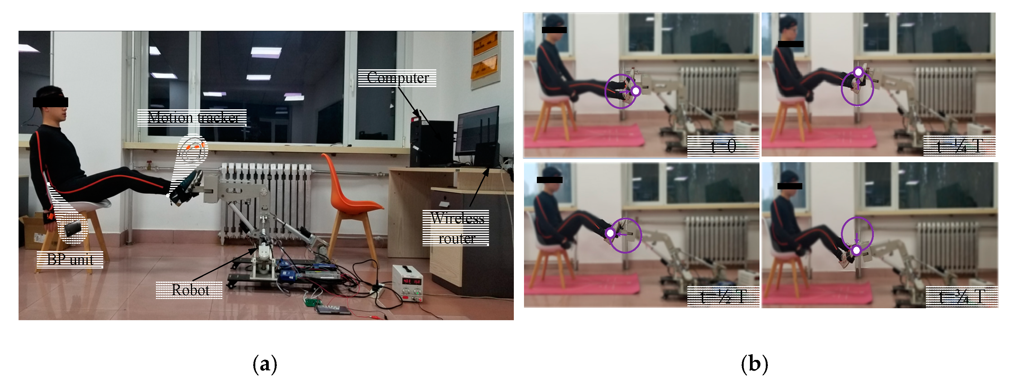
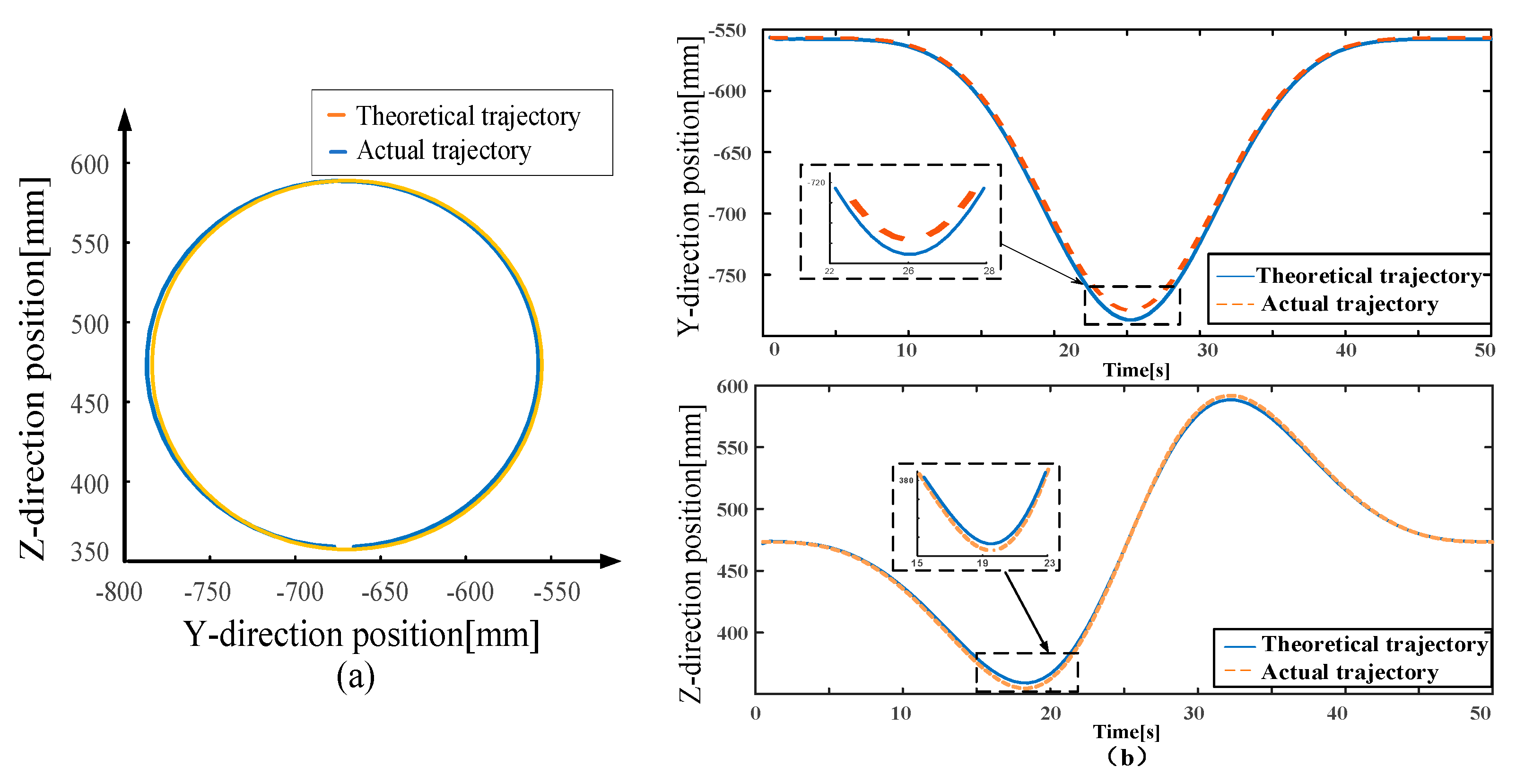
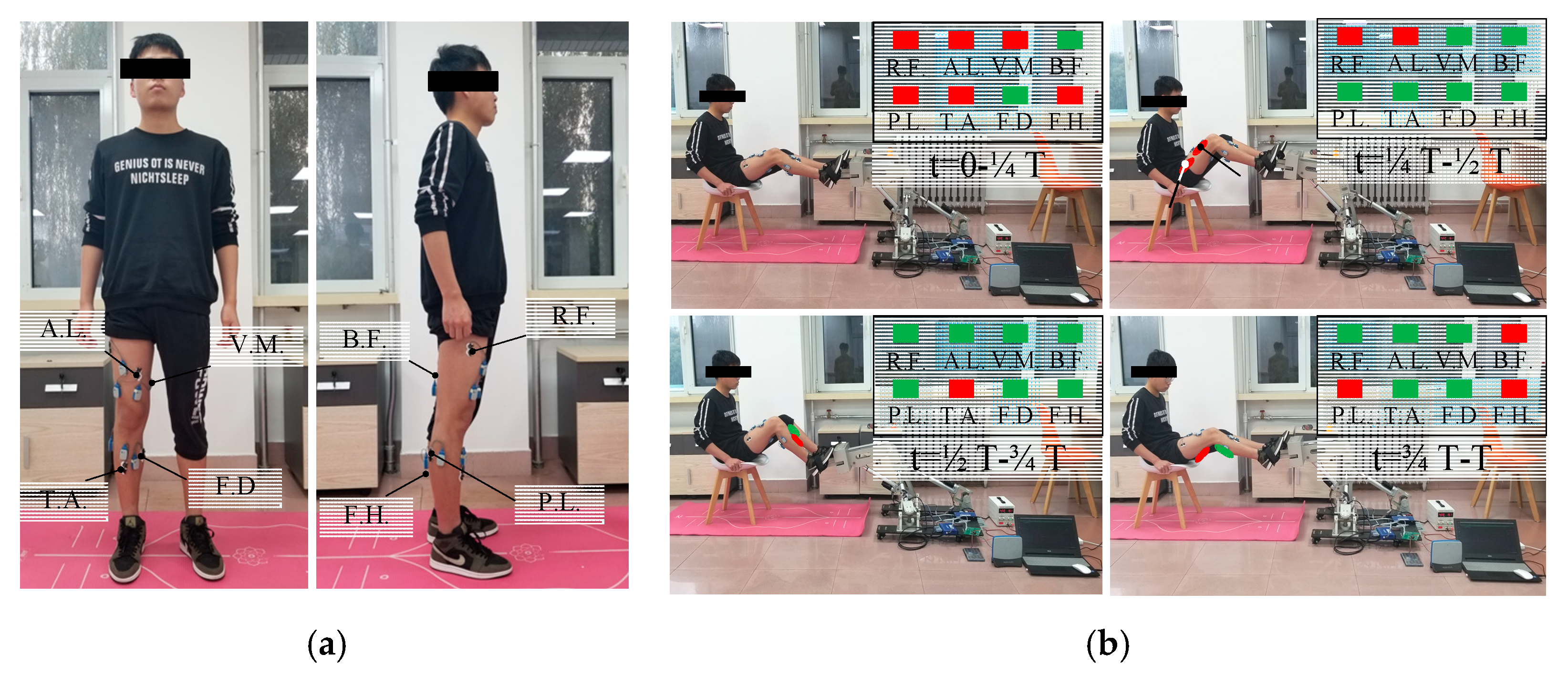
3.1. Motion Capture Experiment

The XsensTM MVN motion capture system was used to verify the robot motion performance and trajectory planning. The inertial sensor of the Xsens MVN motion capture system was worn at the foot of the volunteer, which was fixed on the pedal of the HE-LRR and driven by the HE-LRR to conduct the MOTOmed training. According to the position information acquired by the inertial sensor, the trajectory of the volunteer foot during the MOTOmed exercise training process was obtained. The experimental system is shown in Figure 7. Since the prescribed trajectory was in the sagittal plane, the position information processing and analysis obtained were also carried out in the sagittal plane.
Figure 8 shows the comparison between experimental and theoretical results. It can be seen that the theoretical values of the human foot trajectory had the same trend as the measured values. In thirty training cycles, the maximum position error in the Y direction in the sagittal plane was about 7.55 mm, which occurred at t = 1/4 T; the maximum position error in the Z direction was about −7.37 mm, which occurred during the time from t = 1/4 T to t = 2/4 T. The error sources were mainly from the sliding error between the foot and the pedal as well as the assembly error of the robot. For the rehabilitation training process, the experimental error was within the allowable range, and the actual motion trajectory of the foot was comparatively consistent with the theoretical trajectory, indicating that the HE-LRR possessed good motion performance.

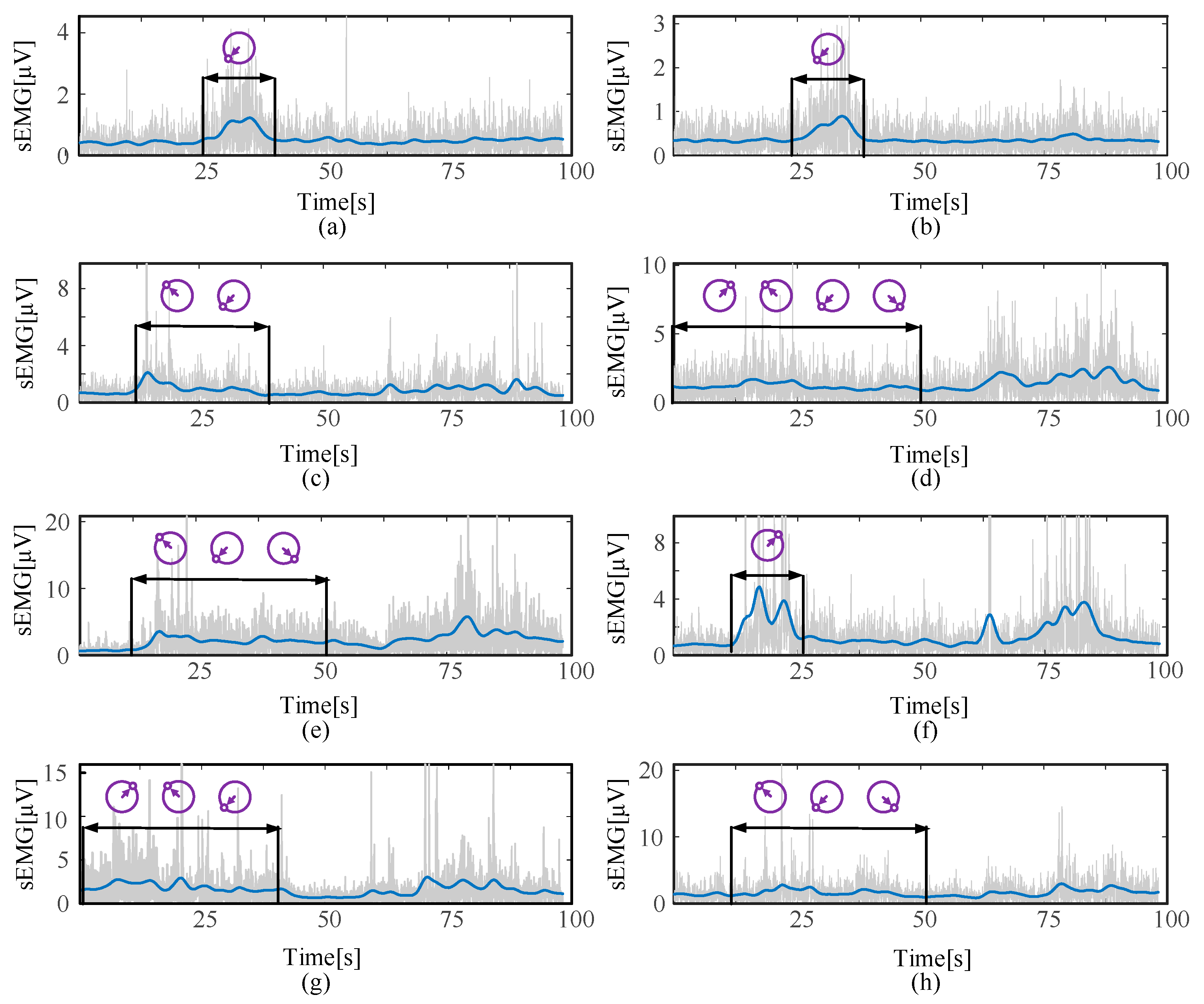
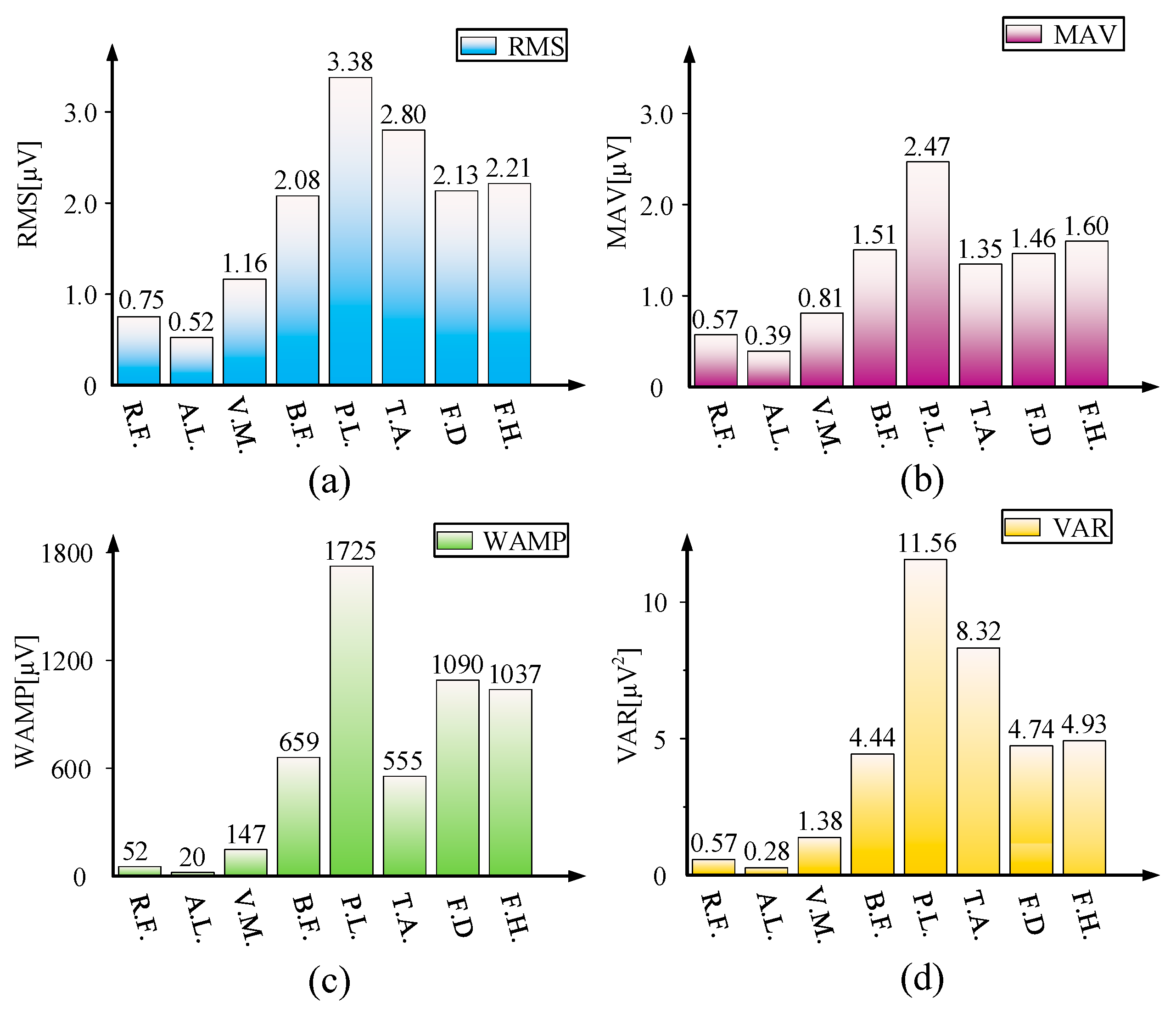
3.2. sEMG Signal Acquisition Experiment

For lower-limb rehabilitation patients, on one hand, exercises should be taken to strengthen the muscles of the patient’s limbs and maintain muscle vitality. On the other hand, repetitive exercises should be performed to promote the self-repair and functional reorganization of the patient’s nervous system to achieve neural circuit reconstruction [30,31,32]. Therefore, for lower-limb rehabilitation robots, in addition to the movement standardization of the limb training, muscle activity evaluation is also essential in this training process. By observing the activity changes of the lower limbs during the training process, guiding the targeted rehabilitation training and evaluating the training effects of patients are of great significance to formulate scientific and standardized rehabilitation programs for patients and improve the comfort and compliance of robots.
Take the MOTOmed exercise training process as an example. As shown in Figure 9, eight main muscle groups of the lower limb were selected as the observation objects, and the UltiumTM sEMG sensor system (Noraxon Corporation) was used to observe the activity changes of the lower limb muscles during the training process. As shown in Figure 10, We acquired the volunteers’ experimental data from the sensors and obtained the final data through full-wave rectification and Gaussian filter. Through experiments, it was found that the main muscle groups of the lower limbs had been activated to varying degrees at different stages of the training cycle. A MOTOmed exercise training cycle was equally divided into four stages according to time. In the first stage, biceps femoris (B.F.) and flexor digitorum longus (F.D.) showed a strong degree of activity, while other muscle groups had weaker activity. In the second stage, except for rectus femoris (R.F.) and adductor longus (A.L.), most muscle groups showed strong activity. This process was maintained until the third stage; the weaker muscle group became tibialis anterior (T.A.), while other muscle groups maintained relatively strong activity. In the fourth stage, except for biceps femoris (B.F.), peroneus longus (P.L.) and flexor hallucis longus muscle (F.H.), other muscle groups showed weaker activity again. It is worth noting that flexor digitorum longus (F.D.) had strong activity in the first three stages, peroneus longus (P.L.) and flexor hallucis longus muscle (F.H.) had strong activity in the latter three stages, and biceps femoris (B.F.) showed relatively strong activity in the full cycle. It also showed that in the process of MOTOmed exercise training, the lower-limb rehabilitation robot had a positive effect on improving muscle activity and promoting the reconstruction of neural circuits by driving the lower limbs of the human body for rehabilitation training.
Furthermore, quantitative analysis was carried out on the sEMG signals of eight major muscle groups of the lower limb in the time domain during one MOTOmed training cycle. Different feature values were utilized to evaluate the sEMG signal change characteristics from various aspects. The root mean square (RMS) and mean absolute value (MAV) can reflect the effective value and average intensity of the signal, Willison amplitude (WAMP) and variance (VAR) can reflect the muscle contraction level and the energy level of the sEMG signal [33,34], and the calculation formulas for feature values are as follows.
{ R M S = n = 1 N x n 2 N M A V = 1 N n = 1 N | x n | W A M P = i = 1 N f ( | x n x n + 1 | ) V A R = 1 N 1 n = 1 N x n 2
By calculating four types of feature values of the volunteer in thirty training cycles, we obtained the statistical characteristics of the sEMG signals of the eight main muscle groups in the MOTOmed training. As shown in Figure 11, the calf muscle group activity (including the muscle contraction level and the sEMG signal energy level) was higher than the thigh muscle group activity. Among the thigh muscle groups, only biceps femoris (B.F.) showed a relatively high degree of activity. Since the MOTOmed training was carried out in the sagittal plane, the participation levels of the thigh rectus femoris (R.F.), adductor longus (A.L.) and vastus medialis were lower. As shown in Figure 11, the HE-LRR actively drove the lower limb to move during passive training, and the signal energy of the eight muscle groups was generally weak. However, the participation levels of eight muscle groups in MOTOmed exercise training showed a clear distinction.

4. Conclusions

In this paper, a novel HE-LRR was designed for the lower-limb rehabilitation requirement of patients in different stages, especially in the acute stage, and evaluated through the experiments. The main conclusions are as follows:
(1) For the HE-LRR, the mobility was calculated and the motion property was analyzed based on the screw theory. Through the above theoretical analysis, the HE-LRR could meet the multi-degree-of-freedom rehabilitation training needs of patients.
(2) The motion capture experiment showed the maximum error of the robot in the Y-axis direction in the sagittal plane was about 7.55 mm, and the maximum error in the Z-axis direction was about −7.37 mm, proving that the HE-LRR achieved relatively high kinematic accuracy.
(3) The sEMG signal acquisition experiment revealed most muscle groups of lower limbs (flexor digitorum longus (F.D.), biceps femoris (B.F.), flexor hallucis longus muscle (F.H.), etc.) had been notably activated when the lower limb was driven by the HE-LRR in the MOTOmed training, illustrating that the HE-LRR could assist the lower limb to achieve satisfactory muscle rehabilitation training effect.

Author Contributions

Methodology, L.W. and J.N.; software, J.D. and S.Z.; validation, S.Z. and Z.Z.; writing—original draft preparation, L.W. and J.T.; writing—review and editing, J.T. and J.W.; project administration, J.N. All authors have read and agreed to the published version of the manuscript.

Funding

This research was funded by the National Key Research and Development Program of China under Grant 2019YFB1312500, in part by the Science and Technology (S&T) Program of Hebei under Grant 216Z1803G and E2020103001.

Institutional Review Board Statement

The study was conducted in accordance with the Declaration of Helsinki, and approved by Ethics Committee of China Rehabilitation Research Center (protocol code: 2020-006-1 and date of approval: March 2020).

Informed Consent Statement

Informed consent was obtained from all subjects involved in the study.

Data Availability Statement

The original data contributions presented in the study are included in the article; further inquiries can be directed to the corresponding authors.

Conflicts of Interest

The authors declare no conflict of interest.

References

  1. Zhou, J.; Li, Z.; Li, X.; Wang, X.; Song, R. Human–Robot Cooperation Control Based on Trajectory Deformation Algorithm for a Lower Limb Rehabilitation Robot. IEEE-ASME Trans. Mechatron. 2021, 26, 3128–3138. [Google Scholar] [CrossRef]
  2. Shi, X.; Wang, H.; Sun, L. Design and dynamic analysis of an exoskeletal lower limb rehabilitation robot. Chin. J. Mech. Eng. 2014, 50, 41–48. [Google Scholar] [CrossRef]
  3. Klamroth-Marganska, V.; Blanco, J.; Campen, K.; Curt, A.; Dietz, V.; Ettlin, T.; Felder, M.; Fellinghauer, B.; Guidali, M.; Kollmar, A.J.T.L.N. Three-dimensional, task-specific robot therapy of the arm after stroke: A multicentre, parallel-group randomised trial. Lancet Neurol. 2014, 13, 159–166. [Google Scholar] [CrossRef]
  4. Major, Z.; Vaida, C.; Major, K.; Tucan, P.; Brusturean, E.; Gherman, B.; Birlescu, I.; Craciunaș, R.; Ulinici, I.; Simori, G.; et al. Comparative Assessment of Robotic versus Classical Physical Therapy Using Muscle Strength and Ranges of Motion Testing in Neurological Diseases. J. Pers. Med. 2021, 11, 953. [Google Scholar] [CrossRef]
  5. Seo, J.; Kim, H. Biomechanical Analysis in Five Bar Linkage Prototype Machine of Gait Training and Rehabilitation by IMU Sensor and Electromyography. Sensors 2021, 21, 1726. [Google Scholar] [CrossRef]
  6. Viekash, V.K.; Arun, P.; Manimozhi, S.; Nagotanekar, G.D.; Deenadayalan, E. Deep Learning Based Muscle Intent Classification in Continuous Passive Motion Machine for Knee Osteoarthritis Rehabilitation. In Proceedings of the IEEE Madras Section Conference, Chennai, India, 27–28 August 2021; pp. 1–8. [Google Scholar]
  7. Wang, C.; Li, Y.; Xiong, Z.; Luo, Y.; Cao, Y. Lower Body Rehabilitation Dataset and Model Optimization. In Proceedings of the 2021 IEEE International Conference on Multimedia and Expo, Shenzhen, China, 5–9 July 2021; pp. 1–6. [Google Scholar]
  8. Shen, C.; Liu, F.; Yao, L.; Li, Z.; Qiu, L.; Fang, S. Effects of MOTOmed movement therapy on the mobility and activities of daily living of stroke patients with hemiplegia: A systematic review and meta-analysis. Clin. Rehabil. 2018, 32, 1569–1580. [Google Scholar] [CrossRef]
  9. Longde, W.; Jianmin, L.; Yi, Y.; Bin, P.; Yilong, W. The prevention and treatment of stroke in China still faces great challenges—Summary of the Report of Stroke Prevention and Treatment in China 2018. Chin. Circ. J. 2019, 34, 105–119. [Google Scholar]
  10. Sun, Z.; Li, F.; Lian, Y.; Liu, S.; Liu, K. An adaptive iterative learning control approach for lower limb rehabilitation robot in noisy environments. In Proceedings of the 2019 IEEE 9th Annual International Conference on CYBER Technology in Automation, Control, and Intelligent Systems (CYBER), IEEE, Suzhou, China, 29 July–2 August 2019; pp. 905–910. [Google Scholar]
  11. Shi, D.; Zhang, W.; Zhang, W. Human-centered adaptive control of lower limb rehabilitation robot based on human–robot interaction dynamic model. Mech. Mach. Theory 2021, 162, 104340. [Google Scholar] [CrossRef]
  12. Almaghout, K.; Tarvirdizadeh, B.; Alipour, K.; Hadi, A. Part H: Design and control of a lower limb rehabilitation robot considering undesirable torques of the patient’s limb. J. Eng. Med. 2020, 234, 1457–1471. [Google Scholar] [CrossRef]
  13. Wang, Y.; Wang, K.; Zhang, Z. Control strategy and experimental research of a cable-driven lower limb rehabilitation robot. IEEE Access 2020, 9, 79182–79195. [Google Scholar] [CrossRef]
  14. Ármannsdóttir, A.L.; Beckerle, P.; Moreno, J.C.; van Asseldonk, E.H.; Manrique-Sancho, M.-T.; Del-Ama, A.J.; Veneman, J.F.; Briem, K.J. Assessing the involvement of users during development of lower limb wearable robotic exoskeletons: A survey study. SAGE Choice 2020, 62, 351–364. [Google Scholar] [CrossRef] [PubMed] [Green Version]
  15. Aurich, T.; Gut, A.; Labruyere, R. The FreeD module for the Lokomat facilitates a physiological movement pattern in healthy people—A proof of concept study. J. Neuroeng. Rehabil. 2019, 16, 1–13. [Google Scholar]
  16. Gandara, T.; Fernande, M.; Rodriguez, A. Robotic systems for gait re-education in cases of spinal cord injury: A systematic review. Rev. De Neurol. 2017, 64, 205–213. [Google Scholar]
  17. Koukolová, I. Overview of the robotic rehabilitation systems for lower limb rehabilitation. Transf. Inovácií 2015, 31, 107–111. [Google Scholar]
  18. Aggogeri, F.; Pellegrini, N.; Adamini, R. Functional design in rehabilitation: Modular mechanisms for ankle complex. Appl. Bionics Biomech. 2016, 21, 1–8. [Google Scholar] [CrossRef] [Green Version]
  19. Aglia, J.; Tsagarakis, N.; Dai, J. Control strategies for patient-assisted training using the ankle rehabilitation robot (ARBOT). IEEE-ASME Trans. Mechatron. 2013, 18, 1799–1808. [Google Scholar]
  20. Abbasnejad, G.; Yoon, J.; Lee, H. Optimum kinematic design of a planar cable-driven parallel robot with wrench-closure gait trajectory. Mech. Mach. Theory 2016, 99, 1–18. [Google Scholar] [CrossRef]
  21. Marghi, Y.; Farjadian, A.; Yen, S. EEG-guided robotic mirror therapy system for lower limb rehabilitation In Proceedings of the 2017 39th Annual International Conference of the IEEE Engineering in Medicine and Biology Society (EMBC). Jeju Island, Korea, 11–15 July 2017; pp. 1917–1921. [Google Scholar]
  22. Liu, W.; Yin, B.; Yan, B. A survey on the exoskeleton rehabilitation robot for the lower limbs. In Proceedings of the 2016 2nd International Conference on Control, Automation and Robotics (ICCAR), Hong Kong, China, 28–30 April 2016; pp. 90–94. [Google Scholar]
  23. Masengo, G. A Design of Lower Limb Rehabilitation Robot and its Control for Passive Training. In Proceedings of the 2020 10th Institute of Electrical and Electronics Engineers International Conference on Cyber Technology in Automation, Control, and Intelligent Systems, Xi’an, China, 10–14 October 2020; pp. 152–157. [Google Scholar]
  24. Liang, F.Y.; Zhong, C.H.; Zhao, X.; Castro, D.L.; Chen, B.; Gao, F.; Liao, W.H. Online Adaptive and LSTM-Based Trajectory Generation of Lower Limb Exoskeletons for Stroke Rehabilitation. In Proceedings of the 2018 IEEE International Conference on Robotics and Biomimetics (ROBIO), Kuala Lumpur, Malaysia, 12–15 December 2018; pp. 27–32. [Google Scholar]
  25. Dai, J.; Mechanisms, K. Geometrical Foundations and Screw Algebra for Mechanisms and Robotics; Higher Education Press: Beijing, China, 2014; pp. 225–235. [Google Scholar]
  26. Niu, J.; Wang, H.; Jiang, Z.; Chen, L.; Zhang, J.; Feng, Y.; Guo, S. Kinematic Analysis of a Serial-Parallel Hybrid Mechanism and Its Application to a Wheel-Legged Robot. IEEE Access 2020, 8, 111931–111944. [Google Scholar] [CrossRef]
  27. Niu, J.; Wang, H.; Shi, H.; Nicolae, P.; Li, D.; Li, S.; Wu, S. Study on Structural Modeling and Kinematics Analysis of a Novel Wheel-Legged Rescue Robot. Int. J. Adv. Robot. Syst. 2018, 15, 1–17. [Google Scholar] [CrossRef] [Green Version]
  28. Yang, H.; Lee, C.; Lin, R. Effect of biofeedback cycling training on functional recovery and walking ability of lower extremity in patients with stroke. Kaohsiung J. Med. Sci. 2014, 30, 35–42. [Google Scholar] [CrossRef] [Green Version]
  29. Skvortsova, V.; Ivanova, G.; Rumiantseva, N. Modern approach to gait restoration in patients in the acute period of cerebral stroke. Vserossiiskoe Obs. Psikhiatrov 2010, 110, 25–30. [Google Scholar]
  30. Wang, S.; Shi, X.; Li, H. DAPK1 Signaling Pathways in Stroke: From Mechanisms to Therapies. Mol. Neurobiol. 2017, 54, 4716–4722. [Google Scholar] [CrossRef] [PubMed] [Green Version]
  31. Jung, J.; Kim, G.; Hai, C. Reperfusion and Neurovascular Dysfunction in Stroke: From Basic Mechanisms to Potential Strategies for Neuroprotection. Mol. Neurobiol. 2010, 41, 172–179. [Google Scholar] [CrossRef] [PubMed] [Green Version]
  32. Rabinowitch, I. Inserting new synaptic connections into damaged neural circuits: Towards synapse therapy. Neural Regen. Res. 2022, 17, 2. [Google Scholar] [CrossRef] [PubMed]
  33. Kyeong, S.; Kim, J. Fatigue characteristics of surface electromyography during walking. In Proceedings of the 2018 18th International Conference on Control, Automation and Systems (ICCAS), PyeongChang, Korea, 17–20 October 2018; pp. 897–899. [Google Scholar]
  34. Kaur, M.; Mathur, S.; Bhatia, D.; Verma, S. EMG analysis for identifying walking patterns in healthy males. In Proceedings of the 2015 11th Conference on Ph. D. Research in Microelectronics and Electronics (PRIME), Glasgow, UK, 29 June 2015; pp. 65–68. [Google Scholar]
Figure 1. Configuration of the HE-LRR. (a) The virtual prototype. (b) The schematic diagram of (2-UPS + U)&(R + RPS) mechanism.
Machines 10 00099 g001
Figure 2. Structure of mirror motion actuator.
Machines 10 00099 g002
Figure 3. The mechanism coordinate system.
Machines 10 00099 g003
Figure 4. Sagittal plane workspace region of human-robot system (plane of YZ).
Machines 10 00099 g004
Figure 5. The displacement, velocity and acceleration of the linear actuator. (Since the position of the linear actuator l02 is no change in the sagittal plane, only the linear actuator l01 and l03 has been shown there).
Machines 10 00099 g005
Figure 6. The prototype and applicable scenes of the HE-LRR. (a) The prototype of a HE-LRR. (b) Training with sitting posture. (c) Training with lying posture.
Machines 10 00099 g006
Figure 7. Motion capture experiment. (a) Motion capture experiment system composition. (b) The process of motion capture experiment; the purple line shows a theoretical terminal track with the contact point between volunteer and the robot.
Machines 10 00099 g007
Figure 8. Results of the motion capture experiment. (a) Theoretical trajectory and actual trajectory. (b) The comparison between theoretical trajectory and actual trajectory in the Y-direction and Z-direction.
Machines 10 00099 g008
Figure 9. (a) Eight major muscle groups and sensor sticking positions. (b) The sEMG signal changes of muscle groups with time during a MOTOmed exercise training cycle. (R.F.: rectus femoris, A.L.: adductor longus, V.M.: vastus medialis, B.F.: biceps femoris, P.L.: peroneus longus, T.A.: tibialis anterior, F.D.: flexor digitorum longus and F.H.: flexor hallucis longus muscle. The red block represents the muscle group is less active, while the green block is more active).
Machines 10 00099 g009
Figure 10. The sEMG signal changes of eight muscle groups in two consecutive cycles. (a) Rectus femoris (R.F.) (b) Adductor longus (A.L.) (c) Vastus medialis (V.M.) (d) Biceps femoris (B.F.) (e) Peroneus longus (P.L.) (f) Tibialis anterior (T.A.) (g) Flexor digitorum longus (F.D.) (h) Flexor hallucis longus muscle (F.H.).
Machines 10 00099 g010
Figure 11. Feature values of sEMG signal in MOTOmed exercise training cycles. (a) Feature values of root mean square (RMS). (b) Feature values of mean absolute value (MAV). (c) Feature values of Willison amplitude (WAMP). (d) Feature values of variance (VAR).
Machines 10 00099 g011
Table 1. Some basic information of volunteers concerning experiments.
NumberAge
(Year)
Height
(cm)
Thigh Length (cm)Leg
Length (cm)
Healthy Condition (Yes/No)
1291704740Yes
2211754840yes
Publisher’s Note: MDPI stays neutral with regard to jurisdictional claims in published maps and institutional affiliations.

