
Theoretical and Numerical Investigations on Static Characteristics of Aerostatic Porous Journal Bearings

1
College of Hydraulic Science and Engineering, Yangzhou University, Yangzhou 225009, China
2
CAE Department, Shanghai Branch, AVIC Xinxiang Aviation Industry (Group) Co., Ltd., Shanghai 201299, China
*
Author to whom correspondence should be addressed.
Machines 2022, 10(3), 171; https://doi.org/10.3390/machines10030171
Submission received: 14 January 2022
/
Revised: 14 February 2022
/
Accepted: 21 February 2022
/
Published: 24 February 2022
(This article belongs to the Special Issue Optimization and Flow Characteristics in Advanced Fluid Machinery)
Abstract
:To investigate the static characteristics of aerostatic journal bearings with porous bushing, the flow model—in which the compressibility of lubricating gas is considered—is established based on the Reynolds lubrication equation, Darcy equation for porous material, and continuity equation. With the finite difference method, difference schemes for non-uniform grids, relaxation method, and virtual node method, the numerical method for the governing equations of compressible flow in porous journal bearings is proposed. The effects of nominal clearance of bearings and compressibility of gas on the static characteristics are analyzed. Under the same minimum film thickness and the same gas compressibility, as the nominal clearance widens, the load capacity, mass flow rate, and power consumption increase. Under the same minimum film thickness and the same nominal clearance, with the increase in gas polytropic index, the load capacity strengthens, while the mass flow rate and power consumption decline. This study could provide a reference for the design of porous journal bearings.
1. Introduction
Aerostatic journal bearings are normally lubricated by externally pressurized gas, holding advantages of high cleanliness, environmental protection, and low viscosity. They are frequently used in high-precision, high-rotating-speed, and extreme conditions, such as high-precision machine tools and high-speed machines [1]. Several restrictor types for aerostatic journal bearings have been developed, such as porous bushing, orifices, and slots. In contrast, porous bushing forms an approximately uniform gas film on the supporting surface, which offers significant load capacity and stable support [2,3].
Due to a micron-scale lubrication gap, shafting alignment, and shafting rotation, it is difficult to conduct experimental research on the static characteristics of the aerostatic porous journal bearing [4,5]. Presently, theoretical models and numerical solutions are the main methods to obtain static characteristics [6,7]. Sneck et al. [8] assumed that the flow in porous bushing was one-dimensional and compressible. The radial integral of the Darcy equation for porous material was substituted into the Reynolds lubrication equation, and a two-dimensional nonlinear partial differential equation was obtained. Stiffening occurs with an increasing eccentricity ratio, especially in short bearings. Majumdar et al. [9] established a three-dimensional flow equation for the porous bushing and a two-dimensional flow equation for the gas film. The finite difference method was used to solve the theoretical model. The steady-state performance characteristics of a stationary and a rotating journal bearing at various design conditions were studied. Singh et al. [10] considered the slip velocity on the interface between porous bushing and gas film for an aerostatic porous journal bearing. Prakash et al. [11] reported that the roughness and slip significantly affect the performance of hydrodynamic bearings. Naduvinamani et al. [12] investigated the effect of constant and cyclic load on the performance of porous short journal bearings. Under a cyclic load, the couple stress fluids provide a reduction in the journal velocity and an increase in the minimum permissible height of squeeze films. Saha et al. [13] found that the restrictive layer significantly influences the performance of porous journal bearing. Elsharkawy et al. [14] investigated the effects of journal misalignment on the performance of porous journal bearings. The effect of journal misalignment is negligible in porous journal bearings when the permeability is high. Lu et al. [15] studied the compressible flow in an aerostatic spherical bearing. Ruan et al. [16] used the perturbation method to solve the gas lubrication equation, and analyzed the operation stability of aerostatic porous journal bearings. It is found that the stability decreases with the increase in the supply pressure and permeability. Miyatake et al. [17] applied a surface-restricted layer into an aerostatic porous journal bearing, which improves the stiffness and stability at high rotating speed. Nicoletti et al. [18,19] adopted the Newton–Raphson method to solve the flow model of aerostatic porous journal bearings. Lee et al. [20] introduced the under-relaxation method to ensure the solution stability of compressible flow and analyzed the geometrical parameters of gas-lubricated porous bearings. The maximum load capacity occurs in the range of feed parameters between 0.5 and 1.0. Nishitani et al. [21] used the perturbation method to solve the dynamic and static characteristics of hydrostatic porous thrust bearings under small eccentricity. The hydrostatic porous thrust bearing has a higher maximum load capacity and slightly lower stiffness in comparison with bearings with capillary restrictors. Chien et al. [22] established a compressible thermohydrodynamic model of journal bearings lubricated with supercritical carbon dioxide. Feng et al. [23,24] considered the effect of temperature on gas properties and material deformation and established a temperature model of porous bearings with a restricted layer. The maximum gas pressure increases and the minimum film thickness decreases when the thermal deformation of the rotor is considered. Böhle et al. [25] established two-dimensional and three-dimensional flow models of hydrostatic porous journal bearings. Bhattacharjee et al. [26] investigated double-layer porous bearings lubricated with micro-polar fluids. Compared with Newtonian lubricants, the micropolar fluid significantly improves lubrication quality. Substantial studies have been contributed to the understanding of porous journal bearings. However, the compressible flow model and numerical solution of porous journal bearings are still open questions. The effects of nominal clearance of bearings and lubricant compressibility on the static characteristics are not yet completely understood.
Commercial computational fluid dynamics software based on three-dimensional Navier–Stokes equations is another method to predict the static characteristics of porous journal bearings [27]. However, considerable grids are required to fill the micron-scale lubrication gap to ensure a good quality of grids. Moreover, it would consume enormous computational resources and time [28,29]. In contrast, the solver based on the Reynolds lubrication equation can readily solve lubrication problems, showing advantages of low computing resource consumption and fast solution.
This study aims to model and solve the compressible flow in porous journal bearings and investigate the effects of nominal clearance and lubricant compressibility on static characteristics. First, a theoretical flow model of the porous bushing and aerostatic film is established. Then, a numerical solution method of the flow model is proposed, and a bearing solver is programmed. Finally, analysis of lubricant nominal clearance and compressibility is performed with the solver.
2. Porous Journal Bearings
Figure 1 shows the nomenclature of porous journal bearings. Aerostatic lubrication means that the journal is supported by externally pressurized gas fed at the bearing inlet, and then the lubricating gas flow exits from the bearing outlet. The nominal clearance is one of the dominant parameters determining static characteristics such as load capacity and power consumption. Five porous journal bearings are designed, and the parameters are shown in Table 1. The only difference in the bearings is the nominal clearance.
3. Theoretical Modeling
3.1. Reynolds Lubrication Equation
The flow in porous journal bearings is assumed to be isothermal, compressible, and laminar. The Reynolds lubrication equation is used to describe the lubricating film flow of porous journal bearings, and the general complete form under steady condition is
where x, y, and z stand for the circumferential, axial, and radial coordinates, respectively. h is the radial clearance function [30]. μ is the dynamic viscosity. u, v, and w represent the circumferential, axial, and radial velocities, respectively. The subscripts a and b represent the components on the journal bearing and bushing, respectively. The following process is to simplify Equation (1) according to the physical condition of a porous journal bearing.
The non-slip boundary condition is applied to the journal, and the squeezing effect is considered [30,31]. Consequently, the velocity boundary conditions on the journal bearing are given as
By substituting Equations (2)–(4) into Equation (1), a simple form for the flow in the lubrication clearance is written as
3.2. Flow Model of Porous Bushing
The flow model of the porous bushing is established based on the Darcy equation for porous material and continuity equation. The assumptions are given as:
(a) The porous bushing is a three-dimensional laminar flow, and the flow inertia effect is neglected.
(b) The permeability of porous material is isotropic.
(c) The lubricant viscosity is constant, and the lubricant density is only related to pressure.
The Darcy equation is given as
where α is the permeability, i is the free index, and j is the dummy index. Equation (6) is substituted into the compressible continuity Equation (7), and the governing equation of porous bushings is obtained, as shown in Equation (8).
According to the assumption (b), the permeability term is cancelled out, and then Equation (8) is rewritten as
In the compressible calculation of porous journal bearings, the non-conservative form of Equation (9) is adopted and converted to the coordinate described in Figure 1, namely the pressure Laplace equation in the cylindrical coordinate is given as
3.3. Flow Model of Lubricating film
The flow model of the aerostatic lubricating film is established based on the Reynolds lubrication equation and Darcy equation. The interface between the porous and film domains is assumed to be a slip boundary condition [32]. Consequently, the circumferential and axial slip velocities are controlled by the Darcy equation, as shown in Equations (11) and (12).
The injection flow from the porous bushing to the lubrication clearance is modeled by the term of radial velocity on the bushing wall, and it is also described by the Darcy equation, as shown in Equation (13).
Equations (11)–(13) are substituted into the Equation (5), the governing equation of aerostatic lubricating film of porous journal bearings is expressed as
The governing equations for the entire flow in porous journal bearings are composed of Equations (10) and (14), and the application scope is shown in Figure 1.
3.4. Boundary Condition
The unknown variables in the above elliptic partial differential equation are pressure and density, which can be solved with the given boundary conditions of pressure and the correlation between pressure and density. Lubricant with certain pressure is supplied at the inlet of the porous bushing and then discharged to the working environment from the bearing outlet. Thus, the Dirichlet boundary condition of pressure (denoted by I in Figure 1) is specified at the bearing inlet and outlet. There is no lubricant passing through the porous bushing end, on which the normal velocity (axial velocity) is 0 m·s−1, as shown in Equation (15).
Subsequently, the Neumann boundary condition of pressure (denoted by II in Figure 1) on the porous bushing end is deduced as
It should be noted that the pressure on the porous bushing end is controlled by both Equations (10) and (16).
3.5. Ideal Gas State Equation
The effect of gas compressibility on the static characteristics of porous journal bearings is considered. The temperature increase is neglected in the aerostatic lubrication [1,2,31]. The density of ideal gas is positively correlated with pressure under isothermal conditions. By considering the variable process of ideal gas, the gas state equation is expressed as
where Rg is the gas constant, and n is the gas polytropic index. The gas polytropic index varies from 1 to 1.4. If the pressure stays constant, the larger the index is, the lower the density is.
4. Numerical Solution
4.1. Grid Generation
The governing equations of porous journal bearings are solved synchronously by the finite difference method. The computational domain is discretized into structured grids, as shown in Figure 2. Uniform node distribution is adopted in the circumferential and axial directions. Non-uniform node distribution with geometric growth is employed in the radial direction, which is written as
where i, j, and k are the indexes for circumferential, axial, and radial difference schemes, respectively.
4.2. Difference Scheme
The central difference schemes are used for the first- and second-order derivatives in the circumferential and axial directions in the governing equations, as shown in Equations (19)–(20).
The three-node forward difference scheme is used for the first-order radial derivative in Equation (14) [33], as shown in Equation (23).
The central difference schemes are used for the first- and second-order radial derivatives in Equation (10) [33], as shown in Equations (24) and (25).
Equations (19)–(22) are of second-order accuracy, while the accuracy of Equation (25) is between first-order and second-order, which depends on the grid growth ratio q. The grid growth ratio is set as 1.1, showing a quasi-second-order accuracy.
The pressure on the bushing end can be calculated by the one-side difference scheme of Equation (16). However, Equation (16) with difference schemes of either first or second-order accuracy converges slowly. As described in Section 3.4, the pressure on the bushing end is simultaneously controlled by the Equations (10) and (16). A Laplace–Neumann virtual node method is proposed as follows:
(a) The virtual node method is used to deal with the Neumann boundary condition [34]. A virtual node is created outside the flow domain, as shown in Figure 2c. The virtual node combined with the central difference scheme is used to discretize Equation (16), which holds second-order accuracy, and then the pressure at the virtual node is yielded, as shown in Equations (26) and (27).
(b) The pressure on the bushing end is also governed by Equation (16). Equations (21), (22), (24), and (25) combined with the virtual node are used to discretize Equation (10), and then the pressure at the virtual node is replaced by Equation (27). Therefore, the second-order axial partial derivative in Equation (10) is discretized by Equation (28).
A linear algebraic equation for the flow model of porous journal bearings is created with the above difference schemes. Then, the relaxation method and root mean square of residuals are introduced to solve the linear algebraic equation iteratively. The Laplace–Neumann virtual node method shows fast convergence rates and small residuals through massive code tests.
4.3. Pressure–Density Coupling Calculation Method
Figure 3 shows the pressure–density coupling calculation strategy. First, the pressure field is calculated with the numerical method described in Section 4.1 and Section 4.2, and this iterative process is called internal iteration. Then, the density field is updated based on the pressure field and Equation (17), and the updated density field is entered to the following pressure calculation, which is an external iteration. The internal iteration is converged when the root mean square of pressure residuals is less than 1 × 10⁻⁶. When the current pressure and density fields are both less by 1 × 10⁻⁴ than the previous fields, the external iterative process is terminated.
4.4. Static Characteristics
The load capacity, mass flow rate and power consumption are investigated. After the flow field converged, the static characteristics are calculated by the following equations.
Load capacity:
Mass flow rate:
Volumetric flow rate:
Power consumption:
Case B under the minimum film thickness of 0.001 mm is selected to conduct grid sensitivity analysis. The circumferential, axial, and radial nodes are adjusted with the same growth ratio. Figure 4 presents the load capacity versus the number of nodes. The load capacity is changeless when the nodes reach 240,000. To balance the calculation accuracy and time efficiency, the number of nodes in the circumferential, axial, and radial directions are determined as 120, 80, and 25, respectively.
5. Results and Discussion
5.1. Effects of Nominal Clearance on Static Characteristics
Figure 5 shows the effect of nominal clearance on the load capacity. The gas polytropic index is set as 1, which means that density linearly relates to pressure. Under the same minimum film thickness, the load capacity increases with the increase in nominal clearance. The eccentricity ratio is defined as the ratio of eccentricity to nominal clearance. For example, when the minimum film thickness is 0.001 mm, the load capacity of nominal clearance of 0.02 mm (the eccentricity ratio is 0.95) is around three times that of nominal clearance of 0.01 mm (the eccentricity ratio is 0.9). However, with the uniform increase in nominal clearance, the growth amplitude of load capacity gradually decreases. For instance, when the minimum film thickness keeps 0.001 mm, the load capacity increases by nearly 80 N as the nominal clearance is increased from 0.01 mm to 0.02 mm; in contrast, with the rise in nominal clearance from 0.04 mm (the eccentricity ratio is 0.975) to 0.05 mm (the eccentricity ratio is 0.98), the load capacity increases only by around 6 N. Under the same nominal clearance, the load capacity decreases with the increase in the minimum film thickness. When no eccentricity occurs, the load capacity is 0 N.
To understand why the load capacity amplifies with nominal clearance for compressible flow in porous journal bearings, the minimum film thickness of 0.001 mm is taken as an example, and the pressure fields of lubricating film with nominal clearances of 0.01 mm, 0.03 mm (the eccentricity ratio is 0.967), and 0.05 mm are compared, as shown in Figure 6. With the increase in nominal clearance, the maximum pressure shows little change and occurs around the circumferential position of 180°, where the minimum film thickness is located. The maximum pressure reaches approximately 4.01 bar under each nominal clearance, which is slightly greater than the feeding pressure because of the aerodynamic effect. However, the pressure at the circumferential position of 0° or 360° decreases remarkably as the nominal clearance increases, which means the circumferential gradient of pressure varies significantly against the nominal clearance. Thus, a greater load capacity is generated.
Figure 7 shows the effect of nominal clearance on mass flow rate. Under the same minimum film thickness, the mass flow rate increases with the increase in nominal clearance. For example, when the minimum film thickness is 0.001 mm, the mass flow rate of nominal clearance of 0.02 mm is approximately 2.3-times higher than that of nominal clearance of 0.01 mm. However, as the nominal clearance rises uniformly, the increased amplitude of mass flow rate gradually decreases. For instance, when the minimum film thickness stands at 0.001 mm, as the nominal clearance is adjusted from 0.01 mm to 0.02 mm, the mass flow rate increases by around 0.05 kg·min−1; by comparison, with the nominal clearance expanded from 0.04 mm to 0.05 mm, the mass flow rate rises by nearly 0.02 kg·min−1. The mass flow rate of nominal clearances of 0.01, 0.02, and 0.03 mm is negatively correlated with the minimum film thickness. Conversely, the mass flow rate of nominal clearances of 0.04 mm and 0.05 mm presents a positive correlation with the minimum film thickness.
Figure 8 shows the effect of nominal clearance on power consumption. Standing at the same minimum film thickness, the power consumption rises with the increase in nominal clearance. The power consumption of nominal clearances of 0.01, 0.02, and 0.03 mm declines as the minimum film thickness increases. However, for nominal clearances of 0.04 mm and 0.05 mm, the power consumption positively correlates with the minimum film thickness.
5.2. Effects of Gas Polytropic Index on Static Characteristics
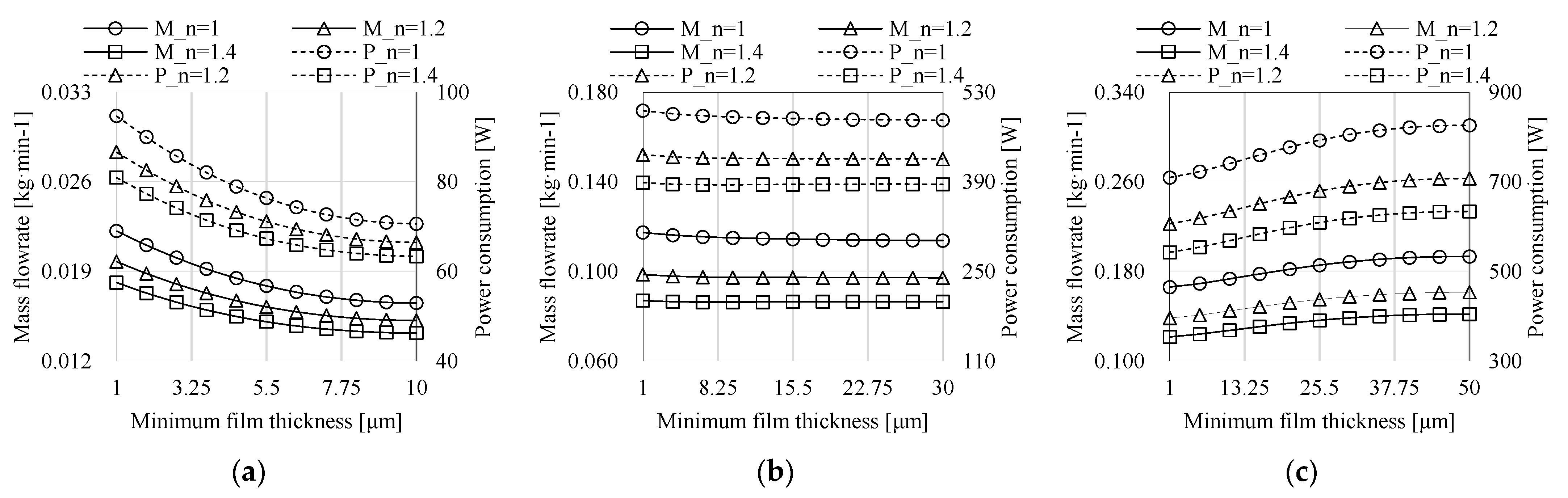
The nominal clearances of 0.01, 0.03, and 0.05 mm are presented to investigate the effect of compressibility on static characteristics. The nominal clearances of 0.02 mm and 0.04 mm show a consistent conclusion. The gas polytropic indices are set as 1, 1.2, and 1.4. The load capacity is shown in Figure 9. Under the same minimum film thickness, the load capacity strengthens with the increase in gas polytropic index. However, as the nominal clearance increases, the increased amplitude of load capacity with regard to the gas polytropic index diminishes. For nominal clearance of 0.05 mm, curves of load capacity versus minimum film thickness for different gas polytropic indexes almost coincide.
Figure 10 shows the effect of gas polytropic index on mass flow rate (denoted as M) and power consumption (denoted as P) under nominal clearances of 0.01, 0.03, and 0.05 mm. Under the same minimum film thickness, the mass flow rate and power consumption decrease with the increase in gas polytropic index. It is opposed to the effect of gas polytropic index on load capacity. That is to say, within the scope of this study, the static performance can be improved by using lubricant with less compressibility. For nominal clearances of 0.01 mm and 0.03 mm, the mass flow rate and power consumption under different gas polytropic indexes are negatively correlated with the minimum film thickness. However, for nominal clearance of 0.05 mm, the mass flow rate and power consumption expand as the minimum film thickness widens.
6. Conclusions
The theoretical model of aerostatic porous journal bearings is established based on the Reynolds lubrication equation, Darcy equation, and continuity equation. The numerical method for the bearing model is proposed with the finite difference method, difference schemes, relaxation method, and virtual node method. Under the same minimum film thickness and the same gas polytropic index, with the increase in nominal clearance, the load capacity strengthens due to the rise in pressure circumferential gradient. Meanwhile, the mass flow rate and power consumption expand. As the nominal clearance widens uniformly, the increased amplitude of load capacity gradually decreases. Under the same minimum film thickness and the same nominal clearance, as the gas polytropic index rises, the load capacity amplifies because the pressure circumferential gradient increases, while the mass flow rate and power consumption decline. The effect of gas polytropic index on load capacity diminishes with the increase in nominal clearance.
Author Contributions
Conceptualization, Y.G. and J.C.; Data curation, Y.G. and J.C.; Formal analysis, Y.G. and J.C.; Investigation, J.C.; Project administration, Y.G.; Resources, Y.G.; Software, Y.G.; Supervision, Y.G.; Validation, J.C., L.L. and C.Z.; Visualization, C.X., L.L. and C.Z.; Writing—original draft, Y.G. and J.C.; Writing—review & editing, Y.G. and J.C. All authors have read and agreed to the published version of the manuscript.
Funding
This research was funded by the Postdoctoral Research Fund of Jiangsu Province, China (grant no. 2021K569C), and National Natural Science Foundation of China (grant no. 51779214).
Institutional Review Board Statement
Not applicable.
Informed Consent Statement
Not applicable.
Data Availability Statement
Data on the analysis and reporting results during the study can be obtained by contacting the authors.
Acknowledgments
The authors thank the College of Hydraulic Science and Engineering, Yangzhou University. The authors acknowledge the funding support from the Postdoctoral Research Fund of Jiangsu Province and National Natural Science Foundation of China. The authors are very grateful for the discussion with Martin Böhle and Artur Schimpf from the Technical University of Kaiserslautern, Germany. A huge thanks is due to the editor and reviewers for their valuable comments to improve the quality of this paper.
Conflicts of Interest
The authors declare no conflict of interest.
Nomenclature
| B | porous bushing thickness |
| E | eccentricity |
| FX | X-direction load capacity |
| FY | Y-direction load capacity |
| F | load capacity |
| h | radial gap function |
| h0 | nominal clearance |
| i | index for circumferential difference scheme |
| j | index for axial difference scheme |
| k | index for radial difference scheme |
| Lp | porous bushing length |
| ṁ | mass flow rate |
| n | rotating speed |
| Nx | circumferential grid node number |
| Ny | axial grid node number |
| Nz | radial grid node number |
| P | power consumption |
| p | pressure |
| ps | feeding pressure |
| pb | backing pressure |
| pv | virtual node |
| pi,j,k | internal node |
| ∆p | feeding pressure difference (∆p = ps − pb) |
| q | grid growth ratio |
| R1 | journal radius |
| R2 | bearing inside radius |
| Rg | gas constant |
| T | temperature |
| u | circumferential velocity |
| ua | journal circumferential velocity component |
| ub | bushing circumferential velocity component |
| ub,s | bushing circumferential slip velocity component |
| v | axial velocity |
| va | journal axial velocity component |
| vb | bushing axial velocity component |
| vb,s | bushing axial slip velocity component |
| w | radial velocity |
| wa | journal radial velocity component |
| wb | bushing radial velocity component |
| wb,s | bushing radial slip velocity component |
| x | circumferential coordinate |
| y | axial coordinate |
| z | radial coordinate |
| Δzk | grid thickness of layer k |
| Greek symbols | |
| ρ | density |
| μ | lubricant dynamic viscosity |
| υ | lubricant kinematic viscosity |
| α | permeability |
| φ | circumferential angle |
| ω | journal angular velocity |
| Superscripts | |
| n | gas polytropic index |
| Subscripts | |
| a | journal component |
| b | bushing component |
| i | free index |
| j | dummy index |
| s | slip velocity |
| x | circumferential |
| y | axial |
| z | radial |
References
- Gu, Y.; Böhle, M.; Schimpf, A.; Yuan, S. Aerostatic bearing with porous restrictor: Research status and future perspectives. J. Drain. Irrig. Mach. Eng. 2021, 39, 818–825. [Google Scholar] [CrossRef]
- Gu, Y.; Böhle, M.; Schimpf, A.; Yuan, S. Theoretical modeling and numerical solution of hydrostatic radial bearing with porous restrictor. J. Vib. Shock. 2021, 40, 16–24. [Google Scholar] [CrossRef]
- Lee, C.C.; You, H.I. Characteristics of externally pressurized porous gas bearings considering structure permeability. Tribol. Trans. 2009, 52, 768–776. [Google Scholar] [CrossRef]
- San Andres, L.; Cable, T.A.; Zheng, Y.; De Santiago, O.; Devitt, D. Assessment of porous type gas bearings: Measurements of bearing performance and rotor vibrations. In Proceedings of the ASME Turbo Expo 2016: Turbomachinery Technical Conference and Exposition, Seoul, Korea, 13–17 June 2016. [Google Scholar] [CrossRef]
- Liu, W.; Feng, K.; Huo, Y.; Guo, Z. Measurements of the rotordynamic response of a rotor supported on porous type gas bearing. J. Eng. Gas Turbines Power 2018, 140, 102501. [Google Scholar] [CrossRef]
- Wang, B.; Wang, Y.; Liu, Y.; Zhu, C.; Yuan, X. Static and dynamic characteristics of tilting-pad thrust bearing on inclined shaft. J. Xi’an Jiaotong Univ. 2020, 54, 129–138. [Google Scholar] [CrossRef]
- Hu, X.; Lü, P.; Feng, K.; Zhao, X. Static and dynamic performance of laminated gas foil thrust bearing. J. Aerosp. Power 2018, 37, 236–241. [Google Scholar] [CrossRef]
- Sneck, H.J.; Yen, K.T. The externally pressurized, porous wall, gas-lubricated journal bearing. ASLE Trans. 1964, 7, 288–298. [Google Scholar] [CrossRef]
- Majumdar, B.C. Analysis of externally pressurized porous gas journal bearings—I. Wear 1975, 33, 25–35. [Google Scholar] [CrossRef]
- Singh, K.C.; Rao, N.S.; Majumdar, B.C. Effect of slip flow on the steady-state performance of aerostatic porous journal bearings. J. Tribol. 1984, 106, 156–162. [Google Scholar] [CrossRef]
- Prakash, J.; Gururajan, K. Effect of velocity slip in an infinitely long rough porous journal bearing. Tribol. Trans. 1999, 42, 661–667. [Google Scholar] [CrossRef]
- Naduvinamani, N.B.; Hiremath, P.S.; Gurubasavaraj, G. Squeeze film lubrication of a short porous journal bearing with couple stress fluids. Tribol. Int. 2001, 34, 739–747. [Google Scholar] [CrossRef]
- Saha, N.; Majumdar, B.C. Study of externally-pressurized gas-lubricated two-layered porous journal bearings: A steady state analysis. Proc. Inst. Mech. Eng. Part J J. Eng. Tribol. 2002, 216, 151–158. [Google Scholar] [CrossRef]
- Elsharkawy, A.A. Effects of misalignment on the performance of flexible porous journal bearings. Tribol. Trans. 2003, 46, 119–127. [Google Scholar] [CrossRef]
- Lu, Z.; Du, J.; Sun, Y. Analysis on aerostatic porous spherical bearings static performance. Chin. J. Mech. Eng. 2004, 2004, 115–119. [Google Scholar] [CrossRef]
- Ruan, H.; Zhang, D.; Jing, X. Analysis on operation stability of porous aerostatic journal bearing. Bearing 2006, 2006, 1–3. [Google Scholar] [CrossRef]
- Miyatake, M.; Yoshimoto, S.; Sato, J. Whirling instability of a rotor supported by aerostatic porous journal bearings with a surface-restricted layer. Proc. Inst. Mech. Eng. Part J J. Eng. Tribol. 2006, 220, 95–103. [Google Scholar] [CrossRef]
- Nicoletti, R.; Silveira, Z.C.; Purquerio, B.M. Modified Reynolds equation for aerostatic porous radial bearings with quadratic Forchheimer pressure-flow assumption. J. Tribol. 2008, 130, 031701. [Google Scholar] [CrossRef]
- Nicoletti, R.; Purquerio, B.D.M.; Silveira, Z.D.C. The effect of permeability distribution on the numerical analysis of aerostatic ceramic porous bearings. Lubr. Sci. 2013, 25, 185–194. [Google Scholar] [CrossRef]
- Lee, C.C.; You, H.I. Geometrical design considerations on externally pressurized porous gas bearings. Tribol. Trans. 2010, 53, 386–391. [Google Scholar] [CrossRef]
- Nishitani, Y.; Yoshimoto, S.; Somaya, K. Numerical investigation of static and dynamic characteristics of water hydrostatic porous thrust bearings. Int. J. Autom. Technol. 2011, 5, 773–779. [Google Scholar] [CrossRef]
- Chien, S.Y.; Cramer, M.; Untaroiu, A. A compressible thermohydrodynamic analysis of journal bearings lubricated with supercritical CO2. In Proceedings of the ASME 2017 Fluids Engineering Division Summer Meeting, Waikoloa, HI, USA, 30 July–3 August 2017. [Google Scholar] [CrossRef]
- Feng, K.; Wu, Y.; Liu, W.; Zhao, X.; Li, W. Theoretical investigation on porous tilting pad bearings considering tilting pad motion and porous material restriction. Precis. Eng. 2018, 53, 26–37. [Google Scholar] [CrossRef]
- Feng, K.; Li, W.; Huo, Y.; Huo, C. Thermal characteristic analysis of aerostatic porous journal bearings with surface-restricted layer. J. Mech. Eng. 2018, 54, 216–224. [Google Scholar] [CrossRef]
- Böhle, M.; Gu, Y.; Schimpf, A. Two flow models for designing hydrostatic bearings with porous material. In Proceedings of the ASME-JSME-KSME 2019 8th Joint Fluids Engineering Conference, San Francisco, CA, USA, 28 July–1 August 2019. [Google Scholar] [CrossRef]
- Bhattacharjee, B.; Chakraborti, P.; Choudhuri, K. Evaluation of the performance characteristics of double-layered porous micropolar fluid lubricated journal bearing. Tribol. Int. 2019, 138, 415–423. [Google Scholar] [CrossRef]
- Wu, D.; Tao, J. Analysis of static performance of porous graphite aerostatic thrust bearing. China Mech. Eng. 2010, 21, 2296–2301. [Google Scholar]
- Cui, H.; Wang, Y.; Yue, X.; Huang, M.; Wang, W. Effects of manufacturing errors on the static characteristics of aerostatic journal bearings with porous restrictor. Tribol. Int. 2017, 115, 246–260. [Google Scholar] [CrossRef]
- Pei, H.; Long, W.; Yang, S.; Gong, L. Formation mechanism of micro-vibration in aerostatic bearings. J. Vib. Shock. 2018, 37, 71–78. [Google Scholar] [CrossRef]
- Böhle, M. Numerical investigation of the flow in hydrostatic journal bearings with porous material. In Proceedings of the ASME 2018 5th Joint US-European Fluids Engineering Division Summer Meeting, Montreal, Qc, Canada, 15–20 July 2018. [Google Scholar] [CrossRef]
- Hamrock, B.J.; Schmid, S.R.; Jacobson, B.O. Fundamentals of Fluid Film Lubrication, 2nd ed.; Marcel Dekker, Inc.: New York, NY, USA, 2004. [Google Scholar] [CrossRef]
- Sparrow, E.M.; Beavers, G.S.; Hwang, I.T. Effect of velocity slip on porous-walled squeeze films. J. Lubr. Technol. 1972, 94, 260–264. [Google Scholar] [CrossRef]
- Ferziger, J.H.; Perić, M.; Street, R.L. Computational Methods for Fluid Dynamics, 3rd ed.; Springer: Berlin/Heidelberg, Germany, 2002. [Google Scholar] [CrossRef]
- Tao, W. Numerical Heat Transfer, 2nd ed.; Xi’an Jiaotong University Press: Xi’an, China, 2001. (In Chinese) [Google Scholar]
Figure 1.
Nomenclature of porous journal bearings.

Figure 2.
Structured grids; (a) Grids for lubricating film; (b) Grids on xz-section; (c) Grids on yz-section.
Figure 2.
Structured grids; (a) Grids for lubricating film; (b) Grids on xz-section; (c) Grids on yz-section.

Figure 3.
Coupling solutions for pressure and density.

Figure 4.
Grid sensitivity analysis.

Figure 5.
Load capacity under different nominal clearances.

Figure 6.
Comparison of lubricating film pressure under different nominal clearances with the minimum film thickness of 0.001 mm; (a) h0 = 0.01 mm; (b) h0 = 0.03 mm; (c) h0 = 0.05 mm.
Figure 6.
Comparison of lubricating film pressure under different nominal clearances with the minimum film thickness of 0.001 mm; (a) h0 = 0.01 mm; (b) h0 = 0.03 mm; (c) h0 = 0.05 mm.

Figure 7.
Mass flow rate under different nominal clearances.

Figure 8.
Power consumption under different nominal clearances.

Figure 9.
Load capacity under different gas polytropic indexes; (a) h0 = 0.01 mm; (b) h0 = 0.03 mm; (c) h0 = 0.05 mm.
Figure 9.
Load capacity under different gas polytropic indexes; (a) h0 = 0.01 mm; (b) h0 = 0.03 mm; (c) h0 = 0.05 mm.

Figure 10.
Mass flow rate and power consumption under different gas polytropic indexes; (a) h0 = 0.01 mm; (b) h0 = 0.03 mm; (c) h0 = 0.05 mm.
Figure 10.
Mass flow rate and power consumption under different gas polytropic indexes; (a) h0 = 0.01 mm; (b) h0 = 0.03 mm; (c) h0 = 0.05 mm.


Table 1.
Parameters of porous journal bearings.
| Parameter | Case A | Case B | Case C | Case D | Case E |
|---|---|---|---|---|---|
| Journal radius R1 (mm) | 15 | 15 | 15 | 15 | 15 |
| Nominal clearance h0 (mm) | 0.01 | 0.02 | 0.03 | 0.04 | 0.05 |
| Bearing inside radius R2 (mm) | 15.01 | 15.02 | 15.03 | 15.04 | 15.05 |
| Porous bushing thickness B (mm) | 5 | ||||
| Porous bushing length Lp (mm) | 38 | ||||
| Dynamic viscosity of lubricant μ (Pa·s) | 1.7894 × 10⁻⁵ | ||||
| Permeability α (m2) | 1 × 10⁻¹³ | ||||
| Rotating speed n (r·min−1) | 5000 | ||||
| Feeding pressure ps (bar) | 4 | ||||
| Background pressure pb (bar) | 1 | ||||
| Feeding pressure difference ∆p = ps − pb (bar) | 3 | ||||
Publisher’s Note: MDPI stays neutral with regard to jurisdictional claims in published maps and institutional affiliations. |
© 2022 by the authors. Licensee MDPI, Basel, Switzerland. This article is an open access article distributed under the terms and conditions of the Creative Commons Attribution (CC BY) license (https://creativecommons.org/licenses/by/4.0/).
Share and Cite
MDPI and ACS Style
Gu, Y.; Cheng, J.; Xie, C.; Li, L.; Zheng, C. Theoretical and Numerical Investigations on Static Characteristics of Aerostatic Porous Journal Bearings. Machines 2022, 10, 171. https://doi.org/10.3390/machines10030171
AMA Style
Gu Y, Cheng J, Xie C, Li L, Zheng C. Theoretical and Numerical Investigations on Static Characteristics of Aerostatic Porous Journal Bearings. Machines. 2022; 10(3):171. https://doi.org/10.3390/machines10030171
Chicago/Turabian StyleGu, Yandong, Jinwu Cheng, Chaojie Xie, Longyu Li, and Changgeng Zheng. 2022. "Theoretical and Numerical Investigations on Static Characteristics of Aerostatic Porous Journal Bearings" Machines 10, no. 3: 171. https://doi.org/10.3390/machines10030171
Note that from the first issue of 2016, this journal uses article numbers instead of page numbers. See further details here.