
Developing a Novel Fully Automated Concept to Produce Bowden Cables for the Automotive Industry

 , , and
Abstract
:1. Introduction
2. Materials and Methods
2.1. Analysis of the Previous Concept
Problem Awareness
- Regarding the operations required for the second terminal injection, the cables were placed in the mushroom-making system and in the injection system manually;
- There is the need to perform trimming and stripping operations for some cable references, requiring a different piece of equipment that must conduct these operations before the cables being placed into the equipment (Figure 2);
- These additional operations induce the need for more workers, as this new equipment requires an operator;
- Improvement of some of the already existing operations is needed by reducing the occupied space of each of the workstations, as well as improving accessibility for maintenance operations.
2.2. Defined Objectives/Requirements
- Integrate the multiple processes currently separated in multiple equipment in a single piece of equipment, which will automatically manage the evolution of the product along the production line, through an appropriate transfer system;
- Produce three different types of cables—IBT, IBT LASSO, and ZZH;
- The equipment must be highly flexible and agile;
- Develop a more complex transfer system that transports the cable across all necessary operations;
- The operations of executing and detecting the mushroom must be automated;
- Staff requirement—one worker/shift (feeding the system and control);
- Aggregation of cutting and stripping operations in the new equipment, removing employees from the production lines and, essentially, from the logistics and reducing the number of different equipment necessary to the production;
- Validation tests must be performed (mushroom inspection, tensile-strength test, and functional length test);
- Extraction system must collect the cables and separate them into OK or NOK;
- The equipment will need to be robust and reduce as much as possible the vibration effect;
- Protective measures shall be in conformity with Machinery Directive 2006/42/EC;
- Good accessibility for maintenance, servicing, and cleaning activities must be kept in mind;
- The machine cycle time should be less than IBT = 7.5 s/cable, ZZH = 9.5 s/cable, and IBT LASSO = 9.5 s/cable (including workers’ manipulation: IBT = 9.5 s/cable, ZZH = 11.5 s/cable, and IBT LASSO = 12.5 s/cable).
2.3. Proposed Concept
- Cutting/trimming and stripping the cable;
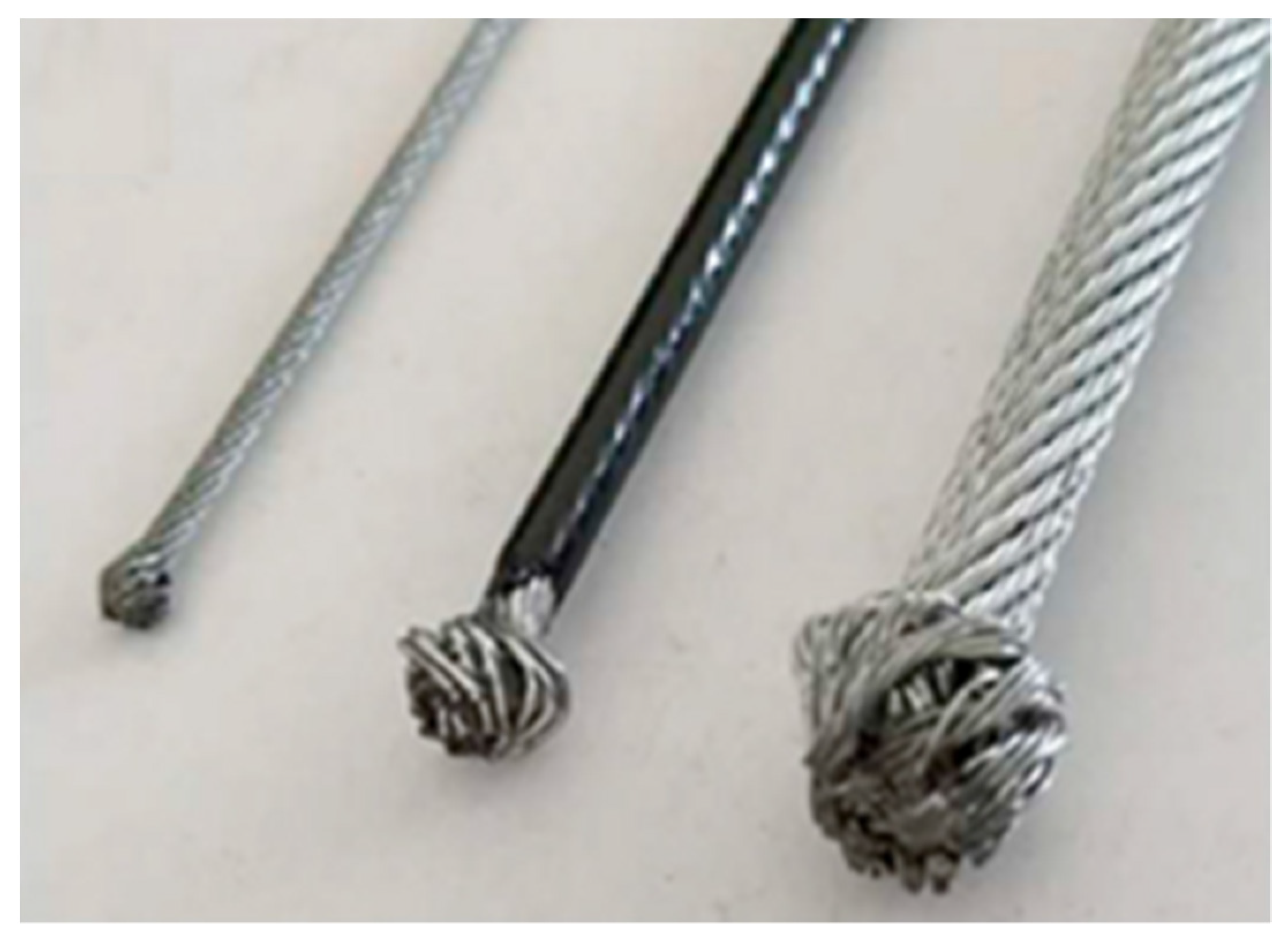
- Mushroom making;
- Zamak terminal injection;
- Sprue-cutting;
- Tensile-strength and length-measurement tests;
- Extraction and separation of the cables into OK and NOK.
3. Results
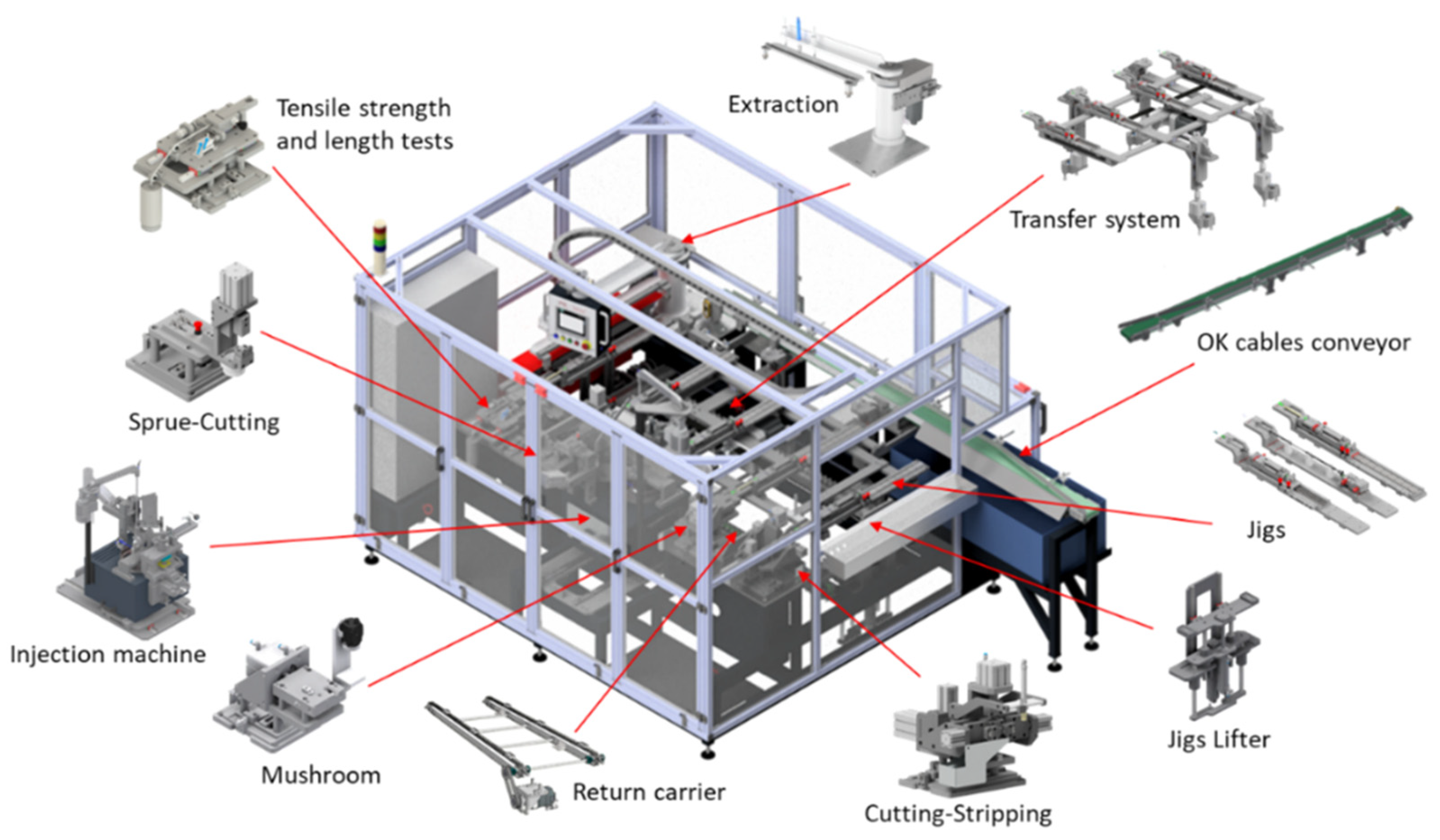
3.1. Equipment Presentation
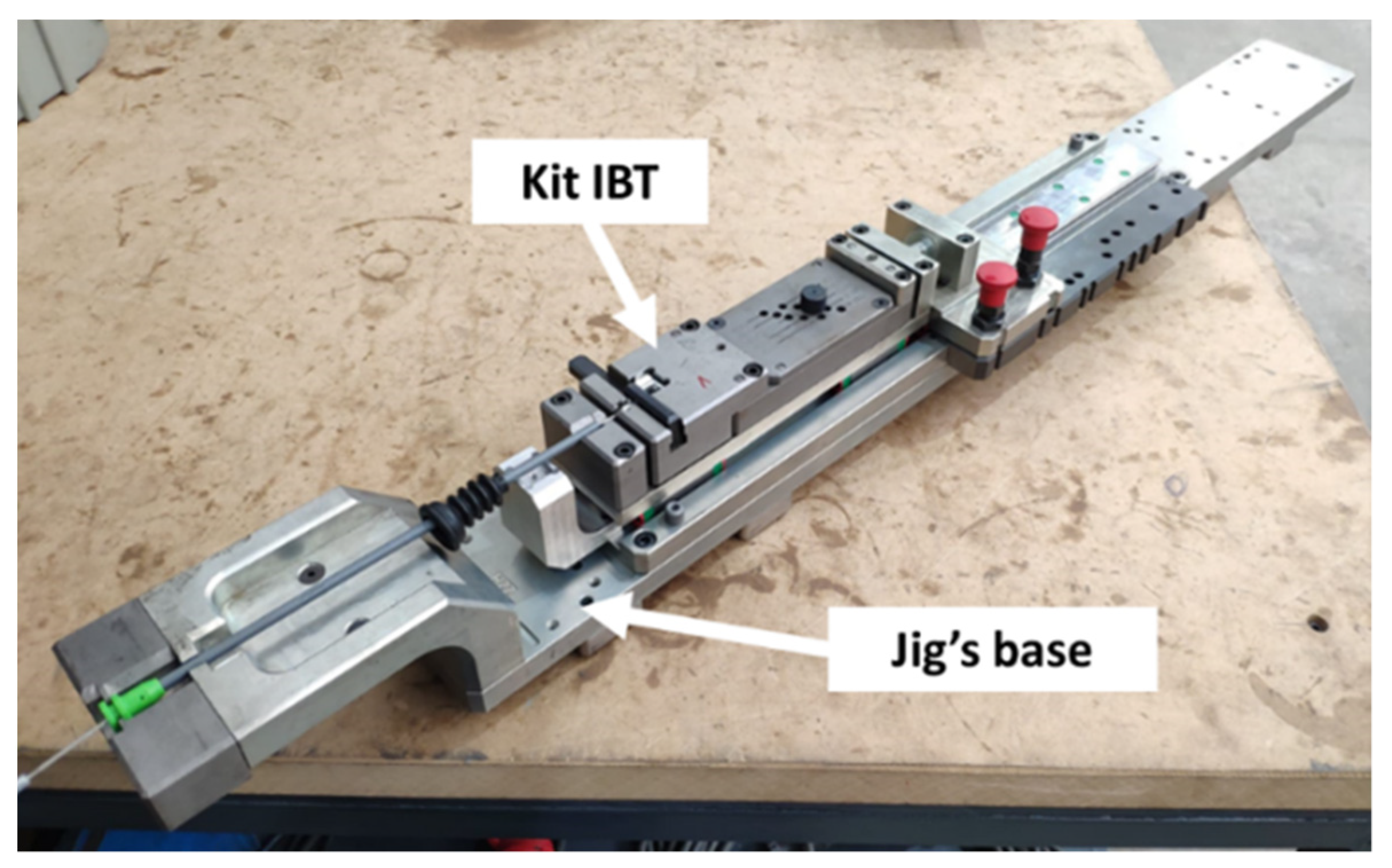
3.1.1. Jigs
3.1.2. Trimming/Cutting and Stripping Workstation
3.1.3. Mushroom-Making Workstation
3.1.4. Zamak Injection Workstation
3.1.5. Sprue-Cutting Workstation
3.1.6. Tensile-Strength and Length-Measurement Tests Workstation
3.1.7. Extraction and Sorting Workstation
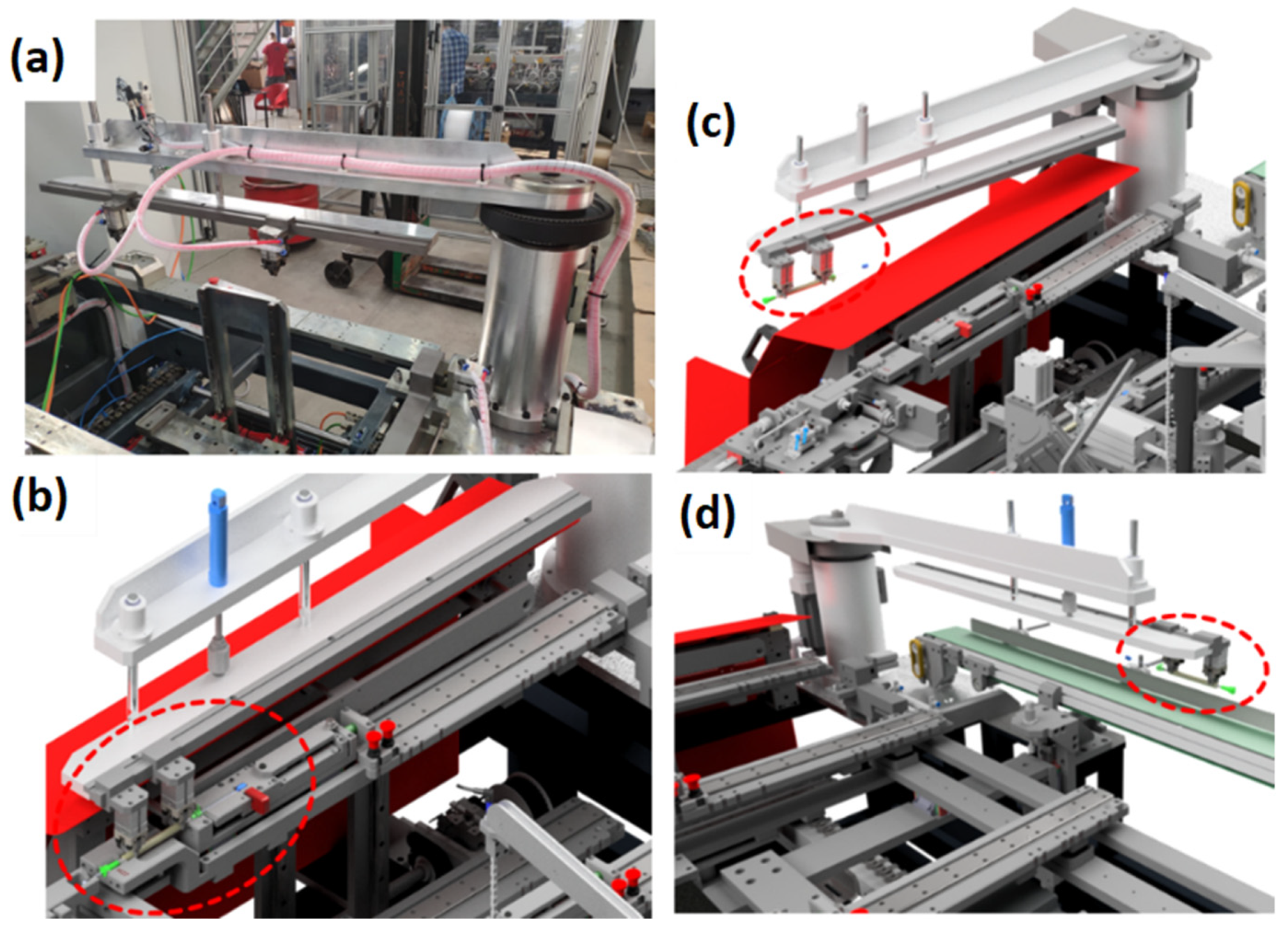
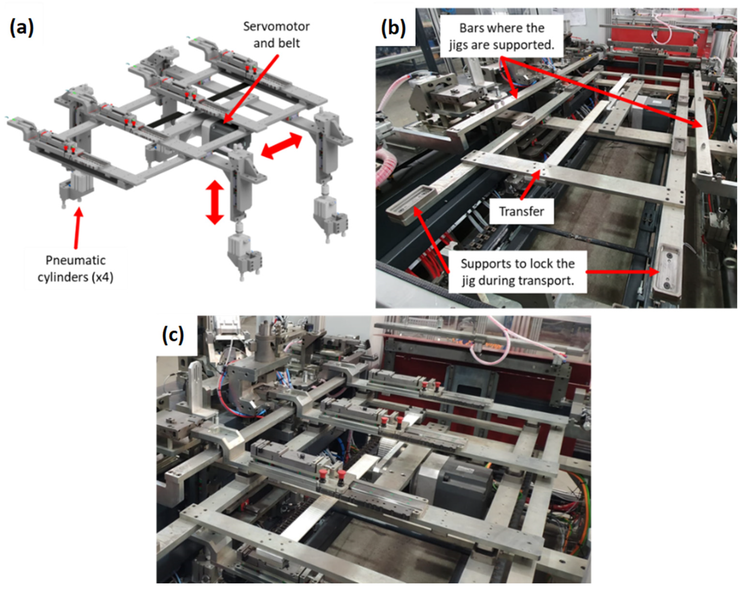
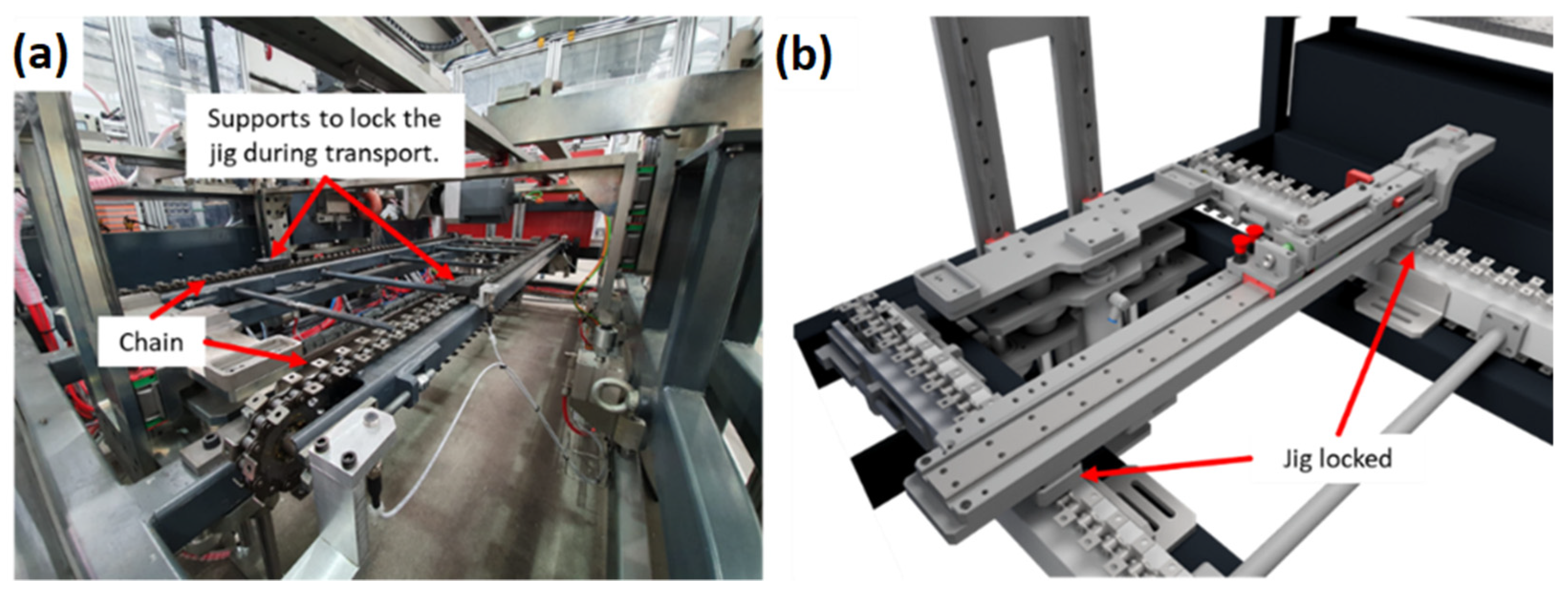
3.1.8. Transfer System
3.1.9. Return Carrier
3.1.10. Jig Lifter
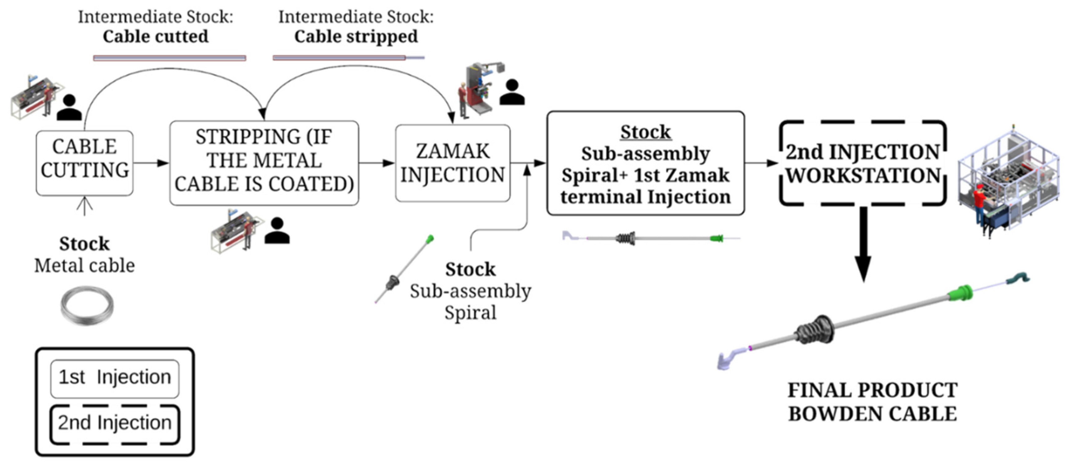
3.2. New Production Process
3.3. Implementation Results
4. Discussion and Conclusions
- Cutting/trimming and stripping the cable;
- Mushroom making;
- Zamak terminal injection;
- Sprue-cutting;
- Tensile-strength and length-measurement tests;
- Extraction and separation of the cables into OK and NOK.
- Two intermediate stocks and associated logistics are eliminated;
- Trimming and stripping operations are integrated into the new equipment:
- Manpower factor is reduced (production and logistics);
- Process flow and work management are improved;
- Single maintenance operation instead of several;
- Increase of the level of automation of the whole process and subsequent reduction of manual operations/repetitive tasks.
Author Contributions
Funding
Data Availability Statement
Acknowledgments
Conflicts of Interest
References
- Pichler, M.; Krenmayr, N.; Schneider, E.; Brand, U. EU industrial policy: Between modernization and transformation of the automotive industry. Environ. Innov. Soc. Transit. 2021, 38, 140–152. [Google Scholar] [CrossRef]
- Abolhassani, A.; Harner, E.J.; Jaridi, M. Empirical analysis of productivity enhancement strategies in the North American automotive industry. Int. J. Prod. Econ. 2018, 208, 140–159. [Google Scholar] [CrossRef]
- Dengiz, B.; Iç, Y.T.; Belgin, O. A meta-model based simulation optimization using hybrid simulation-analytical modeling to increase the productivity in automotive industry. Math. Comput. Simul. 2016, 120, 120–128. [Google Scholar] [CrossRef]
- Lanza, G.; Peters, S.; Herrmann, H.-G. Dynamic optimization of manufacturing systems in automotive industries. CIRP J. Manuf. Sci. Technol. 2012, 5, 235–240. [Google Scholar] [CrossRef]
- Rosa, C.; Silva, F.J.G.; Ferreira, L.P.; Pereira, T.; Gouveia, R. Establishing Standard Methodologies To Improve the Production Rate Of Assembly Lines Used for Low Added-Value Products. Procedia Manuf. 2018, 15, 555–562. [Google Scholar] [CrossRef]
- Dias, P.; Silva, F.J.G.; Campilho, R.D.S.G.; Ferreira, L.P.; Santos, T. Analysis and Improvement of an Assembly Line in the Automotive Industry. Procedia Manuf. 2019, 38, 1444–1452. [Google Scholar] [CrossRef]
- Rosa, C.; Silva, F.J.G.; Ferreira, L.P. Improving the quality and productivity of steel wire-rope assembly lines for the automotive industry. Procedia Manuf. 2017, 11, 1035–1042. [Google Scholar] [CrossRef]
- Ribeiro, P.; Sá, J.C.; Ferreira, L.P.; Silva, F.J.G.; Pereira, M.T.; Santos, G. The Impact of the Application of Lean Tools for Improvement of Process in a Plastic Company: A case study. Procedia Manuf. 2019, 38, 765–775. [Google Scholar] [CrossRef]
- Pinto, H.A.; Silva, F.J.G.; Martinho, R.P.; Campilho, R.D.S.G.; Pinto, A.G. Improvement and validation of Zamak die casting moulds. Procedia Manuf. 2019, 38, 1547–1557. [Google Scholar] [CrossRef]
- Pinto, H.; Silva, F.J.G. Optimization of die casting process in Zamak alloys. Procedia Manuf. 2017, 11, 517–525. [Google Scholar] [CrossRef]
- Sousa, V.F.C.; Silva, F.J.G.; Ferreira, L.P.; Campilho, R.D.S.G.; Pereira, T.; Braga, E. Improving the Design of Nozzles Used in Zamak High-Pressure Die-Casting Process. FME Trans. 2021, 49, 1005–1013. [Google Scholar] [CrossRef]
- Pinto, G.; Silva, F.J.G.; Baptista, A.; Fecheira, J.S.; Campilho, R.D.S.G.; Viana, F. Studying the ZnO formation in coated steel wire ropes for the automotive industry. Procedia Manuf. 2020, 51, 912–919. [Google Scholar] [CrossRef]
- Pinto, G.; Silva, F.J.G.; Baptista, A.; Fecheira, J.S.; Campilho, R.D.S.G.; Viana, F. Investigations on the Oxidation of Zn-coated Steel Cables. FME Trans. 2021, 49, 587–597. [Google Scholar] [CrossRef]
- Sarfraz, M.S.; Hong, H.; Kim, S.S. Recent developments in the manufacturing technologies of composite components and their cost-effectiveness in the automotive industry: A review study. Compos. Struct. 2021, 266, 113864. [Google Scholar] [CrossRef]
- Pichler, M.; Krenmayr, N.; Manek, D.; Brand, U.; Högelsberger, H.; Wissen, M. Beyond the jobs-versus-environment dilemma? Contested social-ecological transformations in the automotive industry. Energy Res. Soc. Sci. 2021, 79, 102180. [Google Scholar] [CrossRef]
- Potter, A.; Graham, S. Supplier involvement in eco-innovation: The co-development of electric, hybrid and fuel cell technologies within the Japanese automotive industry. J. Clean. Prod. 2019, 210, 1216–1228. [Google Scholar] [CrossRef] [Green Version]
- Shivankar, S.D.; Deivanathan, R. Product design change propagation in automotive supply chain considering product life cycle. CIRP J. Manuf. Sci. Technol. 2021, 35, 390–399. [Google Scholar] [CrossRef]
- Lixandru, C.G. Supplier Quality Management for Component Introduction in the Automotive Industry. Procedia Soc. Behav. Sci. 2016, 221, 423–432. [Google Scholar] [CrossRef] [Green Version]
- Dweiri, F.; Kumar, S.; Khan, S.A.; Jain, V. Designing an integrated AHP based decision support system for supplier selection in automotive industry. Expert Syst. Appl. 2016, 62, 273–283. [Google Scholar] [CrossRef]
- Hoeft, F. Internal combustion engine to electric vehicle retrofitting: Potential customer’s needs, public perception and business model implications. Transp. Res. Interdiscip. Perspect. 2021, 9, 100330. [Google Scholar] [CrossRef]
- Konstantinidis, K.P.; Saha, S.; Nielsen, I. Production Scheduling using a Multi-Objective framework in an Automotive Company. IFAC-PapersOnLine 2021, 54, 1087–1091. [Google Scholar] [CrossRef]
- Araújo, W.F.S.; Silva, F.J.G.; Campilho, R.D.S.G.; Matos, J.A. Manufacturing cushions and suspension mats for vehicle seats: A novel cell concept. Int. J. Adv. Manuf. Technol. 2017, 90, 1539–1545. [Google Scholar] [CrossRef]
- Rosa, C.; Silva, F.J.G.; Ferreira, L.P.; Campilho, R. SMED methodology: The reduction of setup times for Steel Wire-Rope assembly lines in the automotive industry. Procedia Manuf. 2017, 13, 1034–1042. [Google Scholar] [CrossRef]
- Costa, R.J.S.; Silva, F.J.G.; Campilho, R.D.S.G. A novel concept of agile assembly machine for sets applied in the auto-motive industry. Int. J. Adv. Manuf. Technol. 2017, 91, 4043–4054. [Google Scholar] [CrossRef]
- Costa, M.J.R.; Gouveia, R.M.; Silva, F.J.G.; Campilho, R.D.S.G. How to solve quality problems by advanced fully-automated manufacturing systems. Int. J. Adv. Manuf. Technol. 2018, 94, 3041–3063. [Google Scholar] [CrossRef]
- Bartoš, M.; Bulej, V.; Bohušík, M.; Stanček, J.; Ivanov, V.; Macek, P. An overview of robot applications in automotive industry. Transp. Res. Procedia 2021, 55, 837–844. [Google Scholar] [CrossRef]
- Santos, P.R.; Silva, F.J.G.; Campilho, R.D.S.G.; Pinto, G.F.L.; Baptista, A. A novel concept of a conduit transport system. Procedia Manuf. 2019, 38, 848–857. [Google Scholar] [CrossRef]
- Munten, P.; Vanhamme, J.; Maon, F.; Swaen, V.; Lindgreen, A. Addressing tensions in coopetition for sustainable innovation: Insights from the automotive industry. J. Bus. Res. 2021, 136, 10–20. [Google Scholar] [CrossRef]
- Zapata, C.; Nieuwenhuis, P. Exploring innovation in the automotive industry: New technologies for cleaner cars. J. Clean. Prod. 2010, 18, 14–20. [Google Scholar] [CrossRef]
- Silva, F.J.G.; Swertvaegher, G.; Campilho, R.D.S.G.; Ferreira, L.P.; Sá, J.C. Robotized solution for handling complex automotive parts in inspection and packing. Procedia Manuf. 2020, 51, 156–163. [Google Scholar] [CrossRef]
- Araújo, L.M.B.; Silva, F.J.G.; Campilho, R.D.S.G.; Matos, J.A. A novel dynamic holding system for thin metal plate shearing machines. Rob. Comput. Integr. Manuf. 2017, 44, 242–252. [Google Scholar] [CrossRef]
- Rojas, A.M.; Barbieri, G. A Low-Cost and Scaled Automation System for Education in Industrial Automation. In Proceedings of the 2019 24th IEEE International Conference on Emerging Technologies and Factory Automation (ETFA), Zaragoza, Spain, 10–13 September 2019; pp. 439–444. [Google Scholar]
- Jenis, J.; Hrček, S. Design of an automated line for pressing cylindrical bushings with screws. Transp. Res. Procedia 2021, 55, 613–620. [Google Scholar] [CrossRef]
- Hagemann, S.; Sünnetcioglu, S.; Stark, R. Hybrid Artificial Intelligence System for the Design of Highly-Automated Production Systems. Procedia Manuf. 2019, 28, 160–166. [Google Scholar] [CrossRef]
- Colledani, M.; Gyulai, D.; Monostori, L.; Urgo, M.; Unglert, J.; Van Houten, F. Design and management of reconfigurable assembly lines in the automotive industry. CIRP Ann. 2016, 65, 441–446. [Google Scholar] [CrossRef] [Green Version]
- Yin, G.; Zhu, Z.; Gong, H.; Lu, Z.; Yong, H.; Liu, L.; He, W. Flexible punching system using industrial robots for automotive panels. Rob. Comput. Integr. Manuf. 2018, 52, 92–99. [Google Scholar] [CrossRef]
- Baskaran, S.; Niaki, F.A.; Tomaszewski, M.; Gill, J.S.; Chen, Y.; Jia, Y.; Mears, L.; Krovi, V. Digital Human and Robot Simulation in Automotive Assembly using Siemens Process Simulate: A Feasibility Study. Procedia Manuf. 2019, 34, 986–994. [Google Scholar] [CrossRef]
- Silva, F.J.G.; Soares, M.R.; Ferreira, L.P.; Alves, A.C.; Brito, M.; Campilho, R.D.S.G.; Sousa, V.F.C. A Novel Automated System for the Handling of Car Seat Wires on Plastic Over-Injection Molding Machines. Machines 2021, 9, 141. [Google Scholar] [CrossRef]
- Figueiredo, D.; Silva, F.J.G.; Campilho, R.D.S.G.; Silva, A.; Pimentel, C.; Matias, J.C.O. A new concept of automated manufacturing process for wire rope terminals. Procedia Manuf. 2020, 51, 431–437. [Google Scholar] [CrossRef]
- Moreira, B.M.D.N.; Gouveia, R.M.; Silva, F.J.G.; Campilho, R.D.S.G. A Novel Concept of Production and Assembly Processes Integration. Procedia Manuf. 2017, 11, 1385–1395. [Google Scholar] [CrossRef]
- Santos, P.M.M.; Campilho, R.D.S.G.; Silva, F.J.G. A new concept of full-automated equipment for the manufacture of shirt collars and cuffs. Rob. Comput. Integr. Manuf. 2021, 67, 102023. [Google Scholar] [CrossRef]
- Santos, R.F.L.; Silva, F.J.G.; Gouveia, R.M.; Campilho, R.D.S.G.; Pereira, M.T.; Ferreira, L.P. The Improvement of an APEX Machine involved in the Tire Manufacturing Process. Procedia Manuf. 2018, 17, 1571–1578. [Google Scholar] [CrossRef]
- Veiga, N.F.M.; Campilho, R.D.S.G.; Silva, F.J.G.; Santos, P.M.M.; Lopes, P.V. Design of automated equipment for the assembly of automotive parts. Procedia Manuf. 2019, 38, 1316–1323. [Google Scholar] [CrossRef]
- Vaishnavi, V.K.; Kuechler, W. Introduction to Design Science Research in Information and Communication Technology. In Design Science Research Methods Patterns Innovative Information Communication Technology, 2nd ed.; CRC Press: Boca Raton, FL, USA, 2015; pp. 7–30. [Google Scholar]
- Abdullah, O.I.; Abbood, W.T.; Hussein, H.K. Development of Automated Liquid Filling System Based on the Interactive Design Approach. FME Trans. 2020, 48, 938–945. [Google Scholar] [CrossRef]
- Tamada, S.; Chandra, M.; Patra, P.; Mandol, S.; Bhattacharjee, D.; Dan, P.K. Modeling for Design Simplification and Power-Flow Efficiency Improvement in an Automotive Planetary Gearbox: A Case Example. FME Trans. 2020, 48, 707–715. [Google Scholar] [CrossRef]


| Step | Description |
|---|---|
| Problem awareness | Analysis of the previous concept, determining various problems and aspects that can be improved |
| Define objectives for a solution | Define various objectives/requirements for a solution for the identified problems |
| Design and development | Based on the requirements, design and develop new solution |
| Demonstration | Implementation of the developed concept |
| Evaluation | Evaluate the performance of the developed solution, verifying if the set requirements were met |
| Conclusions | Final evaluation of the solution, offering a comparison between the previous and newly developed concepts |
| Operation | Description |
|---|---|
| Mushroom making | Performs a mushroom at the tip of the cable (Figure 1), preventing the cable from sliding into the Zamak injected part |
| Terminal injection | Injection of the Zamak terminal |
| Validation tests | Performance of tensile-strength and length-measurement tests, determining if the cable satisfies the requirement to advance for the next stage |
| Sprue-cutting and extraction | After validation, the cables are placed into a sprue-cutting mechanism; then they are extracted from the machine and sorted |
| Previous Concept | New Concept | Percentage Deviation | |
|---|---|---|---|
| Cycle time (s) | 12.5 | 9.5 | −25% |
| Production (cables/hour) | 288 | 378 | +30% |
Publisher’s Note: MDPI stays neutral with regard to jurisdictional claims in published maps and institutional affiliations. |
© 2022 by the authors. Licensee MDPI, Basel, Switzerland. This article is an open access article distributed under the terms and conditions of the Creative Commons Attribution (CC BY) license (https://creativecommons.org/licenses/by/4.0/).
Share and Cite
Sousa, V.F.C.; Silva, F.J.G.d.; Campilho, R.D.S.G.; Pinto, A.G.; Ferreira, L.P.; Martins, N. Developing a Novel Fully Automated Concept to Produce Bowden Cables for the Automotive Industry. Machines 2022, 10, 290. https://doi.org/10.3390/machines10050290
Sousa VFC, Silva FJGd, Campilho RDSG, Pinto AG, Ferreira LP, Martins N. Developing a Novel Fully Automated Concept to Produce Bowden Cables for the Automotive Industry. Machines. 2022; 10(5):290. https://doi.org/10.3390/machines10050290
Chicago/Turabian StyleSousa, Vitor Fernando Crespim, Francisco José Gomes da Silva, Raul Duarte Salgueiral Gomes Campilho, Arnaldo Guedes Pinto, Luís Pinto Ferreira, and Nuno Martins. 2022. "Developing a Novel Fully Automated Concept to Produce Bowden Cables for the Automotive Industry" Machines 10, no. 5: 290. https://doi.org/10.3390/machines10050290