
Operational Stability Analysis on the Roller-Coating Process for a Roll Coating-Simulation Test Equipment


College of Mechanical Engineering, Donghua University, Shanghai 201620, China
*
Author to whom correspondence should be addressed.
Machines 2022, 10(5), 304; https://doi.org/10.3390/machines10050304
Submission received: 25 March 2022
/
Revised: 21 April 2022
/
Accepted: 23 April 2022
/
Published: 25 April 2022
(This article belongs to the Special Issue Advances in Applied Mechatronics)
Abstract
:In the research on key technology of radiation-curing coil steel coating, it is necessary to evaluate the coating stability of radiation-curing coil steel coating materials. In this paper, a roll coating-simulation test equipment is proposed to test coating status. Considering the operational stability of the equipment, dynamic vibration response analysis and stability analysis of the roller-coating process are performed on the equipment. The test results show that the rotor vibration of the designed roll coating-simulation test equipment meets the requirements of rotating machinery, and the coating thickness remains stable under the vibration condition, which satisfies the working condition of the test equipment.
1. Introduction
Roll coating has been widely used in the production of steel plate coating due to its advantages of high productivity, stable and uniform coating, and low pollution. In the past, solvent-based coating materials were usually used as surface coating materials in steel plate coating by steel enterprises, which would cause serious environmental pollution. In the steel industry, radiation-curing coating, as a new type of coating material, is favored for its energy efficiency, economy, and greater environmental friendliness. With the advancement of China’s national strategic goal of “Carbon Peak” and “Carbon neutral”, in recent years, it has attracted extensive attention and has been developed [1]. However, in terms of the coating materials in practical applications, it is found that in the roller-coating process, due to the influence of the temperature, viscosity, roller speed, vibration stability, and other factors of the coating, the coating material will form bubbles on the surface of the steel plate, resulting in defects on the surface of the coating, and some parameters for the stability of the coating material have to be evaluated before a coating implementation [2]. Therefore, a test equipment is needed to evaluate the roll coating performance of coating materials.
In the roller-coating process, coating thickness is an important index to evaluate coating quality. By establishing the theoretical relationship between coating thickness and roll coating parameters, reasonable parameters could be obtained theoretically, which can significantly save the cost of roll coating. On the basis of lubrication theory, Savage [3,4] established the variation equation of the coating thickness at the gap between two rollers by separation model and Reynolds model. Through the comparison and analysis with the experimental results, it is found that the two models are suitable for different capillary numbers, and the appropriate model needs to be selected according to the specific situation in different situations. In the same way, Greener [5,6] analyzed Newtonian fluid and derived the relational expression between coating thickness and roll coating parameters (among them the main influencing parameters are roller velocity, radius of the rollers and separation surface thickness), which provided the basis for the subsequent derivation. From the viewpoint of coating material flow, M. Zafar [7] applied the lubrication approximation theory to simplify the flow equations and derived the exact solutions for velocity and pressure profiles, and obtained that the coating thickness is affected by the flow parameters. While it only considered symmetry as a case, the asymmetry was not discussed in detail. Taking the rolling process into account, Muhammad Zahid [8] described the process of extruding a film into a non-Newtonian fluid by establishing a roll coating model between the two counter-rotating rollers. The result indicates that the coating parameters could be controlled by changing the values of the material parameters, which provided a quick and convenient reference for the coating process. Given the extrusion and deformation, M Zahid [9] obtained the maximum pressure and coating thickness by using a regular perturbation method. All that work is an attempt to theoretically establish a suitable relationship between the coating property parameters and the thickness of the roller-coating in the roller-coating process and is also a commonly used analytical method to explore the stability of the roller-coating process theoretically. In addition, for the transformation of the film during the coating process, H. Benkreira [10] pointed that the flow stability has three types of defects: rivulets, air entrainment due to dynamic wetting failure, and cascade, occurring at different values of speed ratio and capillary number.
With the development of numerical analysis technology, the numerical calculation has become a facilitative method to the analysis of the roller-coating process. Utilizing the computational fluid dynamics (CFD) method, Chien [11,12] simulated the roller-coating process and found that the coating thickness was mainly determined by the roller velocity. Meanwhile, a result comparison was implemented between the simulation and the experiment, which demonstrated that the simulation calculation method in roller-coating process simulation is feasible. Furthermore, Kapur’s [13] study of the factors that influence coating quality showed that not only does the roller velocity play an important role in a roll coating process, but also the roller velocity ratio. In addition, factors such as clearance and viscosity also have an influence. These numerical simulation methods provide new ways for the study of roll coating process stability. However, for different coating properties and process parameters, some model parameters applied to the numerical methods require experimental verification or empirical acquisition.
In actuality, with the change of process parameters required for the production, the unstable operation of the coating process is often the case. During a roller-coating process, if the coating exhibits phenomena such as fog and ribbing, it indicates that the roll coating is running under an unstable state. The roller velocity and the viscosity of the coating materials are considered to be the main factors affecting these undesirable phenomena [14,15,16]. Pitts and Greiller [17] found that at low velocities the coating maintained a uniform thickness, while at higher velocities, regular ridges appeared on the surface, then a stability criterion was established to discriminate the influence of disturbance according to the established model. Masato Sasaki [18] found that the extrusion pressure is generated between the steel roller and the rubber roller during the roller-coating process, and the pressure could deform the rubber roller surface, which in turn affects the shape and flow of the gap between the two rollers. Therefore, due to changes in the gap between the rollers, the uniformity of the coating is different compared to when the rigid rollers are used. Additionally, Bettina Grashof [19] also considered that the roller thickness fluctuations can affect the clearance, and thus developed a new criterion for the critical rubber cover thickness, which calculates the limit value of the negligible influence of the rubber cover thickness on the stability. At present, limited research exists into the instability of the roller-coating process, most of which analyzes the overall process under ideal conditions without considering the influence of the roll coating equipment’s structural dynamics parameters on the roller-coating process.
In the steel industry, it is a trend that the radiation-curing coating process replaces the traditional heating curing one. However, there is currently little data on the application of radiation-curing coating materials. In order to have a reasonable and comprehensive evaluation of the operating performance parameters of the radiation-curing material before a production implementation, it is necessary to conduct operational evaluations of different formulations for formal production. Sometimes it is inconvenient to obtain accurate results by using theoretical or numerical methods, and there will be some inconsistence with theory in actual production, Therefore, a roll coating simulation test equipment was designed in this work according to the actual needs of the enterprise, which is designed to test the rationality of the roll coating parameters and the stability of the roller-coating process based on theoretical research combined with the test.
In this paper, for the designed equipment, the dynamic analysis of the vibration in the process of operation is carried out, and the roller-coating process simulation is conducted under the condition of the vibration, the influence of vibration on the stability of the roller-coating process is analyzed, and the rationality of the design and the feasibility of the equipment are verified through the experimental tests. Roller-coating is widely used in steel sheets coating with traditional heat-curing coating method but has surprisingly received little research attention. The radiation-curing coating process is a new attempt in the field of large-scale steel sheets coating production. Therefore, the test equipment proposed in this manuscript is the test equipment prepared for the commissioning of the radiation-curing coatings before the production of the radiation-curing coating process of steel sheets. The implementation of this test could obtain the relevant parameters of the coating process before the large-scale coating production, which can effectively reduce the problems that occur in the production and reduce the production cost.
2. Roll Coating Simulation Test Equipment
2.1. Design and Modeling
The model of the roll coating simulation test equipment is shown in Figure 1. The roller velocity is controlled by a servo motor, the distance between the rollers is controlled by a mobile platform, the coating temperature is controlled by a calorifier under the coating tank, and the properties of the coating are investigated by adjusting the roll coating parameters such as rotational velocity, clearance and coating materials temperature, or the viscosity. The stability of roll coating during operation is a point in the design of the test equipment; the unstable vibration of the equipment will cause the coating materials to shake off, cause an uneven coating, or damage equipment components during the roller-coating process.
2.2. Design and Requirements of Rotor Components
The test equipment is required for a maximum linear velocity of 250 m/min at work. At the velocity, the coating is rolled up, coated, and reflowed by the drawing roller. Therefore, it is important to design the structure of the two rollers. If the diameter is too small, for the rollers with a slender shaft, with the rotor velocity increase, this will cause the coating to splash. Although increasing the diameter of the rotor can effectively reduce the coating materials splashing phenomenon caused by excessive angular velocity, the rotor rotation dynamic imbalance is easy to cause due to the manufacturing errors and the elastic deformation of the shaft in the rotation operation. Therefore, it necessary to analyze the dynamic unbalance vibration response of roll coating rotor components and the stability of roll coating with vibration.
3. Dynamics Simulation and Roll Coating Simulation
3.1. Vibration Response Analysis of Rotor Components
3.1.1. Theory of Unbalanced Vibration Analysis
For the designed rotor components, unbalanced vibration may occur in the process of rotation due to the existence of unbalanced mass associated with the manufacturing error. Since the size and distribution of the unbalanced mass are difficult to determine, the stability of the equipment is verified by calculating the vibration under the limit conditions and analyzing the unbalanced mass. Figure 2 shows the dynamic model of the roll coating rotor, where Ω is the rotational velocity, the bearing stiffness in the X and Y directions are represented by kxx and kyy, and the bearing damping in the X and Y directions are represented by cxx and cyy, respectively.
The equation of motion of the multi-degree-of-freedom vibrating rotor-bearing system is
where M, C, G, and K denote the mass matrix, damping matrix, gyroscopic matrix, and stiffness matrix in the elastomer, respectively, q is the deformation displacement vector of the elastomer, and Ω is its rotational velocity. When the roll coating rotor rotates in a certain plane, it is assumed that due to the existence of unbalanced mass [20], at the unbalanced mass, there is a deviation qε between the equilibrium position and the center of mass. Considering the influence of the deviation, q in Equation (1) is replaced by q + qε, and the equation can be obtained
Since both excitation and response are harmonics, namely, , Equation (2) can be simplified as
For a certain characteristic node k, assuming that there exists no unbalanced displacement ε and unbalanced angle β, the displacement vector qk can be expressed as
where φ and ϕ is the deflection angle generated by unbalanced forces and moments relative to the plane XOY, and the four degrees of freedom are 4k − 3, 4k − 2, 4k − 1, and 4k, respectively. Formalize it as follows
Here, j is a complex number and represents its correlation function, and the following equation is obtained
Finally, the following equation is obtained
where Ω2b0 accounts for the force acting on a certain node. Except for this node, it is assumed that other nodes are in an ideal state, namely that there exists no unbalanced mass and the remaining Ω2b0 = 0. Therefore, there is
The steady-state response of the unbalanced mass to the whole is obtained by solving the Equation (8). Let (q0 is a complex number), q0 is
3.1.2. Unbalance Response Analysis of Rotor Components
In the design of this equipment, each roll coating rotor is installed on two bearings on the mobile platform, and the mobile platform is installed on two sliding guide rails. Vibration is the main interference factor affecting the quality of roll coating when the rotors work within the regular velocity range. In order to study the influence of the roller vibration, the rotational velocity of the roller at the limiting case (1000 rpm) is taken here, and the unbalanced mass is applied to the maximum deformation of a modal analysis within the range of manufacturing errors, based on which the maximum amplitude of vibration excited by the rotor is calculated and the stability of the rotor is investigated. The amplitude in the direction between rollers is shown in Figure 3a, and the amplitude in the direction of gravity is shown in Figure 3b.
It can be seen from Figure 3a,b that the vibration amplitude of the roller direction is basically the same as that of the gravity direction, and the amplitude is less than 6 × 10⁻⁵ m (0.06 mm), which is less than 0.13 mm at 1000 r/min rotational velocity specified by the vibration value of rotating machinery (according to the ISO 7919). Figure 3c shows the calculated critical vibration acceleration (about 5 m/s2) before the unstable operation of the equipment occurring. On this basis, the vibration acceleration is calculated, and the results are shown in Figure 3d. It can be observed that the amplitude of the overall vibration acceleration 2.5 m/s2 is less than critical one 6.5 m/s2, which is stable within a small vibration range, indicating that the overall roll coating rotor operates stably.
3.2. Stability Analysis of Roll Coating
3.2.1. Theoretical Derivation of Roll Coating Stability
The equipment mainly simulates the action of the drawing roller, bringing coating material to the coating roller and the changing state of coating material during long-time roll coating. In this process, the roller velocity ratio is usually set as 1. Due to the different surface roughness of the rollers, the coating thickness will be slightly different. The surface coating thicknesses of the two rollers are denoted as H1 and H2, respectively. Assuming the inlet coating thickness is Hin, the simplified model of the roller-coating process is shown in Figure 4.
Through experimental observation, it is found [21] that in the roller-coating process, when the drawing roller contacts with the coating roller, the coating roller tends to take away part of the surface coating material, then the part will form a uniform and dense coating on the surface of the coating roller. The other parts that are not taken away by the coating roller still remain on the surface of the drawing roller, and then return to the coatings tank with the rotation of the drawing roller. The coating thickness of the two rollers is closely related to the rotational velocity of the two rollers. According to the Landau–Levich equation, the coating thicknesses of the two rollers [22] are obtained as
where S is the velocity ratio (U2/U1) between the two rollers, H1 and H2 denote the coating thickness at the outlet of the drawing roller and coating roller, respectively, Ca is the capillary number based on the average velocity between the rollers, and RXs is the radius of the meniscus.
At the meniscus interface Xs, the coating pressure [17] is PXs = −σ/RXs, where σ is the surface tension coefficient, and RXs is the radius of the meniscus at Xs. A small disturbance ε is generated due to the vibration and other reasons, causing the position of the meniscus to move to another position Xs+ε, and the new position pressure is P(Xs+ε) = −σ/R(Xs+ε). Figure 5 below reveals the meniscus change.
The Taylor expansion of Equation (13) is obtained as follows
Since the higher-order infinitesimal in Taylor’s equation can be ignored, substituting the coating pressure boundary condition PXs = −σ/RXs into Equation (12), the following equation is obtained
Take F as the judging factor affecting the stability of roll coating by disturbance (if F ≥ 0, the roll coating will not be affected by disturbance, and will stabilize again after disturbance); Therefore, the condition that the system can still maintain equilibrium after perturbation is
the pressure gradient in the coaxial roll coating region is required by the Reynold’s equation
where Q is the regional flow, H(X) is the clearance between the two rollers at the coordinate X, and R is the diameter of the two rollers. At the meniscus, there exists
Substitute the above equation as well as Equations (10) and (11) about H1 and H2 into Equation (16), and then get
Given Ca1 = μU1/σ, Ca2 = μU2/σ, and Equation (19), the equation can be simplified as
After deriving the final equation, it can be found that small disturbances can be ignored in the determination of roll coating stability. The equation also illustrates that the roll coating stability is related to the velocity ratio of the two rollers, the radius of the rollers and the distance between the two rollers. On the roller-coating simulation test equipment, the coating properties are mainly observed, and the roll velocities, clearance, and coating viscosity are also analyzed.
3.2.2. Simulation of the Roller-Coating Process
Taking the coating roller and the drawing roller as the objects, the roll coating model, as shown in Figure 6, is constructed to simulate the actual production status and analyze the influence of vibration on the coating quality in the roller-coating process. To study the stability of the roller-coating process, the quality of the coating during the roller-coating process (namely, the uniformity of the coating, the coating thickness) is mainly observed as a criterion for judging the stability of the roll coating. In order to observe the coating quality, the analysis is carried out by monitoring the variation of coating thickness. When the rotational velocity is set at 200 r/min, the clearance is 2 mm, the viscosity is 0.5 Pa·s, and the variation curve of coating thickness is shown in Figure 7.
The figure reveals that the coating material begins to flow through the monitoring line from 0.025 s, and it begins to stabilize at a uniform coating thickness at 0.12 s after coating thickness changes due to vibration, indicating that as the roll coating proceeds, the coating will be stable in the process of change, and eventually form a uniform coating of a certain thickness. By comparison, it is found that the coating thickness will stabilize to a uniform value faster without considering vibration. Despite the increasing instability of the coating under vibration, the overall effect is small.
- (1)
- Influence of roller velocity on roll coating stability under vibration condition
Under the condition that other parameters remain unchanged, the stability of roll coating under different rotational velocities is observed by adjusting roller velocity, as shown in Figure 8. It can be seen from Figure 8 that with the increase of roller velocity, the coating will shorten the time to reach the stable state, and the vibration effect will be reduced, which indicates that when considering vibration, the higher the velocity, the faster the coating reaches the stable state. The results show that the designed rotor components can ensure the stability of the roller-coating process considering vibration.
- (2)
- Influence of coating viscosity on roll coating stability under vibration condition
As the coating viscosity is an important factor affecting the roller-coating process parameters, the stability changes of coating with different coatings viscosity are calculated, as shown in Figure 9. It can be seen from the figures that with the increase of coatings viscosity, the influence of vibration on the roll coating stability is not obvious, which indicates that the change of coating materials viscosity has no significant impact on the roll coating stability. In addition, coating materials viscosity shows a negative correlation with the change in coating thickness.
- (3)
- Influence of distance between rollers on roll coating stability under vibration condition
The distance between the two rollers [24] also has a certain influence on roll coating stability. The variation of the coating stability under different distances is shown in Figure 10. It can be seen from the below figures that, with the increase of distance between the two rollers, the most obvious change is that the coating thickness after stabilization increases significantly; in the case of vibration, the effect of vibration gradually decreases as the clearance increases. It can also be seen from the figures that the larger the distance, the smoother the coating reaches the equilibrium process.
4. Experimental Research and Discussion
4.1. Stability Test of Roll Coating Rotor Components
In order to test the stability of the equipment in actual operation and verify the results of the above simulations, the vibration experiment platform is constructed as shown in Figure 11a, and the vibration accelerations in three directions under spatial coordinates are tested. Set the rotational velocity to 200 r/min, 400 r/min, 600 r/min, 800 r/min, and 1000 r/min, respectively, to record the experimental data. The experimental results are shown in Figure 12. In the figures, the vibration acceleration of rollers clearance direction is represented by AccX; the axial vibration acceleration of the roller is represented by AccY and the vibration acceleration of the roller in the direction of gravity is represented by AccZ. It can be seen from Figure 13 that with the increase of the rotational velocities, the vibration in X, Y, and Z directions will increase significantly, while the overall amplitude is small and relatively uniform, demonstrating the excellent stability of the designed roll coating rotor components within the rated rotational velocity range. Meanwhile, a roller-coating effect test is implemented to verify the operational status when the equipment runs under the regular conditions (as shown in Figure 11b). It is observed that the equipment works stably, the coating is uniform, and no bubbles and fog occur.
4.2. Discussion and Analysis
The above analysis reveals that, although increasing the diameter of the rotor can effectively avoid the coating material splashing, it will also cause the operation imbalance generated by the increase of machining error. On this basis, the vibration response of roll coating rotor components under the limit condition is analyzed according to the allowable unbalance mass. The analysis shows that the amplitudes of roll coating rotor components in different directions are all about 0.06 mm, which is smaller compared with the clearance. The overall vibration amplitude is relatively stable, while the balance value is different due to a certain degree of flexing of the roll coating rotor components under gravity, as shown in Figure 13. For subsequent comparison and experimental verification, the vibration acceleration is calculated. The overall vibration acceleration does not exceed 2.5 m/s2. The results obtained from the experiment are compared with the simulation results, as shown in Figure 14.
According to the figure above, comparing the experimental and the simulation results, it can be seen that the amplitude of vibration acceleration in the direction of rollers is much smaller than the simulation result in the limit case (2.5 m/s2). In the process of roll coating, the radial vibration of the rotor has the most significant influence on the stability of roll coating. This is due to the fact that the radial vibration will significantly affect the distance between rollers, resulting in the change of coating thickness. The experimental values are within the range of the simulation, which indicates that the actual rollers’ unbalanced mass caused by manufacturing error is much less than the allowable one, and the operation process satisfies the actual stability requirements.
After the disturbance is introduced, the correlation coefficient R of the coating variation curve under different parameters is calculated according to the Pearson correlation coefficient. Under the same roller-coating parameters, the coating thickness variable data without considering vibration and with vibration is calculated as follows, and the correlation coefficient between the two data is calculated. Where the correlation coefficient R is also called the degree of fitness, the closer its value is to 1, the higher the fitness of the two curves, indicating that the thickness of the coating is closer to the situation without considering vibration when vibration is considered. Therefore, it can be said that the closer the correlation coefficient is to 1, the less the vibration has an effect on the thickness of the coating. The specific correlation coefficient is shown in Table 1.
The result shows that when the vibration of the roll coating simulation test equipment is considered, the coating thickness will fluctuate during the period from start-up to coating stability, but it will eventually stabilize at the same thickness under normal conditions, indicating that the design of the roll coating rotor conforms with the test standard. In addition, by means of changing the parameters, it can be found through simulation calculation that increasing the rotational velocity of the roller can effectively increase the stability of the roll coating and increase the thickness of the coating after stabilization, while the change range is relatively small. Increasing the viscosity of the coating materials has little effect on the stability of the roll coating and the thickness of the coating. The change of the distance between rollers will cause obvious changes in coating thickness, and as the clearance increases, the effect of vibration on the stability of the roller-coating will be significantly reduced.
In summary, the designed equipment satisfies the stability requirements of the test through experimental verification. According to the results obtained by the test equipment, on one hand, the vibration amplitude of the roll coating rotor components is small during operation, which avoids the strong vibration problem of the whole equipment during service; on the other hand, the experimental results obtained under the conditions of maximum limit parameters are smaller than the dynamic simulation results, indicating that the above analysis of the stability of actual roll coating is reliable, and the stability of the roller-coating process can be guaranteed during operation.
5. Conclusions
In this paper, a roll coating simulation test equipment is proposed to test the roll coating performance of radiation-curing coating materials. In accordance with the requirements of the equipment’s operation stability, the vibration of the main components of the equipment that affects the stability of the roller components is analyzed. The effect of roll coating parameters on roll coating stability is simulated and experimentally studied, and the results are as follows:
- (1)
- Based on the requirements of the roll coating equipment and the theoretical analysis of vibration, a dynamic model of roll coating rotor components is established. Through numerical simulation and experiment, it is obtained that the vibration amplitude of the equipment does not exceed 0.06 mm, and the vibration acceleration is much less than the critical value, which satisfies the vibration requirements under the specified rotational velocity of the vibration value of rotating machinery standard, and the stability requirements of the test equipment under the maximum limit condition.
- (2)
- In the simulation of the roller-coating process, the correlation coefficients of the curves before and after the introduction of the disturbance amount are calculated, and the results are all above 0.95. The overall equipment can still ensure good stability even when vibration is considered. It can be found from further analysis of the influencing factors that the increase of the rotational velocity and the distance between the two rollers can significantly improve the stability of the roll coating, while the viscosity has little effect on that. The results provide a theoretical and experimental reference for the design of this type of roll coating equipment.
Author Contributions
Conceptualization, H.L.; methodology K.Y. and J.Y.; theoretical analysis and validation, K.Y., H.L. and J.Y.; writing—original draft preparation, H.L. and K.Y.; writing—review and editing, H.L., J.Y. and S.W.; funding acquisition, H.L. All authors have read and agreed to the published version of the manuscript.
Funding
This research was partly supported by the National Key Research and Development Program of China, grant number 2018YFB2001502.
Institutional Review Board Statement
Not applicable.
Informed Consent Statement
Not applicable.
Data Availability Statement
Not applicable.
Acknowledgments
The authors would like to thank the Shanghai Baoshan Iron & Steel Co., Ltd. for the experimental support.
Conflicts of Interest
The authors declare no conflict of interest.
References
- Chen-Yang, Y.W.; Chuang, J.R.; Yang, Y.C.; Li, C.Y.; Chiu, Y.S. New UV—Curable cyclotriphosphazenes as fire—Retardant coating materials for wood. J. Appl. Polym. Sci. 1998, 69, 115–122. [Google Scholar] [CrossRef]
- Ali, F.; Hou, Y.; Zahid, M.; Rana, M.A. Theoretical study of the reverse roll coating of non-isothermal magnetohydrodynamics viscoplastic fluid. Coatings 2020, 10, 940. [Google Scholar] [CrossRef]
- Savage, M. Mathematical models for coating processes. J. Fluid Mech. 1982, 117, 443–455. [Google Scholar] [CrossRef]
- Savage, M. Variable speed coating with purely viscous non-Newtonian fluids. Z. Angew. Math. Phys. ZAMP 1983, 34, 358–369. [Google Scholar] [CrossRef]
- Greener, J.; Sullivan, T.; Turner, B.; Middleman, S. Ribbing instability of a two-roll coater: Newtonian fluids. Chem. Eng. Commun. 1980, 5, 73–83. [Google Scholar] [CrossRef]
- Greener, J.; Middleman, S. Reverse roll coating of viscous and viscoelastic liquids. Ind. Eng. Chem. Fundam. 1981, 20, 63–66. [Google Scholar] [CrossRef]
- Zafar, M.; Rana, M.; Zahid, M.; Malik, M.; Lodhi, M. Mathematical analysis of roll coating process by using couple stress fluid. J. Nanofluids 2019, 8, 1683–1691. [Google Scholar] [CrossRef]
- Zahid, M.; Zafar, M.; Rana, M.A.; Lodhi, M.S.; Awan, A.S.; Ahmad, B. Mathematical analysis of a non-Newtonian polymer in the forward roll coating process. J. Polym. Eng. 2020, 40, 703–712. [Google Scholar] [CrossRef]
- Zahid, M.; Haroon, T.; Rana, M.; Siddiqui, A. Roll coating analysis of a third grade fluid. J. Plast. Film Sheeting 2017, 33, 72–91. [Google Scholar] [CrossRef]
- Benkreira, H.; Shibata, Y.; Ito, K. The fluid mechanics of tensioned web roll coating. Chem. Eng. Sci. 2021, 239, 116612. [Google Scholar] [CrossRef]
- Chien, C.-H.; Jang, J.-Y. Numerical and experimental studies of thin liquid film flow between two forward-rollers. J. Mech. Sci. Technol. 2007, 21, 1892–1900. [Google Scholar] [CrossRef]
- Carvalho, M.; Scriven, L. Three-dimensional stability analysis of free surface flows: Application to forward deformable roll coating. J. Comput. Phys. 1999, 151, 534–562. [Google Scholar] [CrossRef]
- Kapur, N. A parametric study of direct gravure coating. Chem. Eng. Sci. 2003, 58, 2875–2882. [Google Scholar] [CrossRef]
- Ascanio, G.; Carreau, P.; Brito-De La Fuente, E.; Tanguy, P. Forward deformable roll coating at high speed with Newtonian fluids. Chem. Eng. Res. Des. 2004, 82, 390–397. [Google Scholar] [CrossRef]
- Ascanio, G.; Carreau, P.; Tanguy, P. High-speed roll coating with complex rheology fluids. Exp. Fluids 2006, 40, 1–14. [Google Scholar] [CrossRef]
- Roper, J.A., III; Salminen, P.; Urscheler, R.; Bousfield, D.W. Studies of orange peel formation in high-speed film coating. Tappi J. 1999, 82, 231–238. [Google Scholar]
- Pitts, E.; Greiller, J. The flow of thin liquid films between rollers. J. Fluid Mech. 1961, 11, 33–50. [Google Scholar] [CrossRef]
- Sasaki, M.; Miyake, M.; Nakata, N. Visualization study of flow stability in reverse roll coating. ISIJ Int. 2015, 55, 863–869. [Google Scholar] [CrossRef] [Green Version]
- Grashof, B.; Delgado, A. Analysis of influencing parameters in deformable roll coating of counter-rotating rolls. J. Coat. Technol. Res. 2015, 12, 63–73. [Google Scholar] [CrossRef]
- Liu, J.N. Rotordynamic Characteristic Research for the Active Magnetic Bearing—Rotor System of Flywheel Energy Storage System; Harbin Engineering University: Harbin, China, 2014. [Google Scholar]
- Carvalho, M. Effect of thickness and viscoelastic properties of roll cover on deformable roll coating flows. Chem. Eng. Sci. 2003, 58, 4323–4333. [Google Scholar] [CrossRef]
- Wilson, M.; Gaskell, P.; Savage, M. Flow in a double-film-fed fluid bead between contra-rotating rolls Part 1: Equilibrium flow structure. Eur. J. Appl. Math. 2001, 12, 395–411. [Google Scholar] [CrossRef] [Green Version]
- Kapur, N.; Gaskell, P.; Bates, A. A parametric study of offset gravure coating. Chem. Eng. Res. Des. 2001, 79, 41–50. [Google Scholar] [CrossRef]
- Greener, J.; Middleman, S. Theoretical and experimental studies of the fluid dynamics of a two-roll coater. Ind. Eng. Chem. Fundam. 1979, 18, 35–41. [Google Scholar] [CrossRef]
Figure 1.
Model of roll coating simulation test equipment. (1—HMI, 2—Power distribution cabinet, 3—Roll coating rotor components, 4—Mobile platform).
Figure 1.
Model of roll coating simulation test equipment. (1—HMI, 2—Power distribution cabinet, 3—Roll coating rotor components, 4—Mobile platform).

Figure 2.
The dynamic model of roll coating rotor components.

Figure 3.
The vibration amplitude and the acceleration of the roller at 1000 rpm. (a) Vibration amplitude diagram of rollers direction; (b) Vibration amplitude diagram of gravity direction; (c) The calculated critical vibration acceleration before the unstable operation of the equipment occurring; and (d) Vibration acceleration diagram of rollers’ direction and gravity.
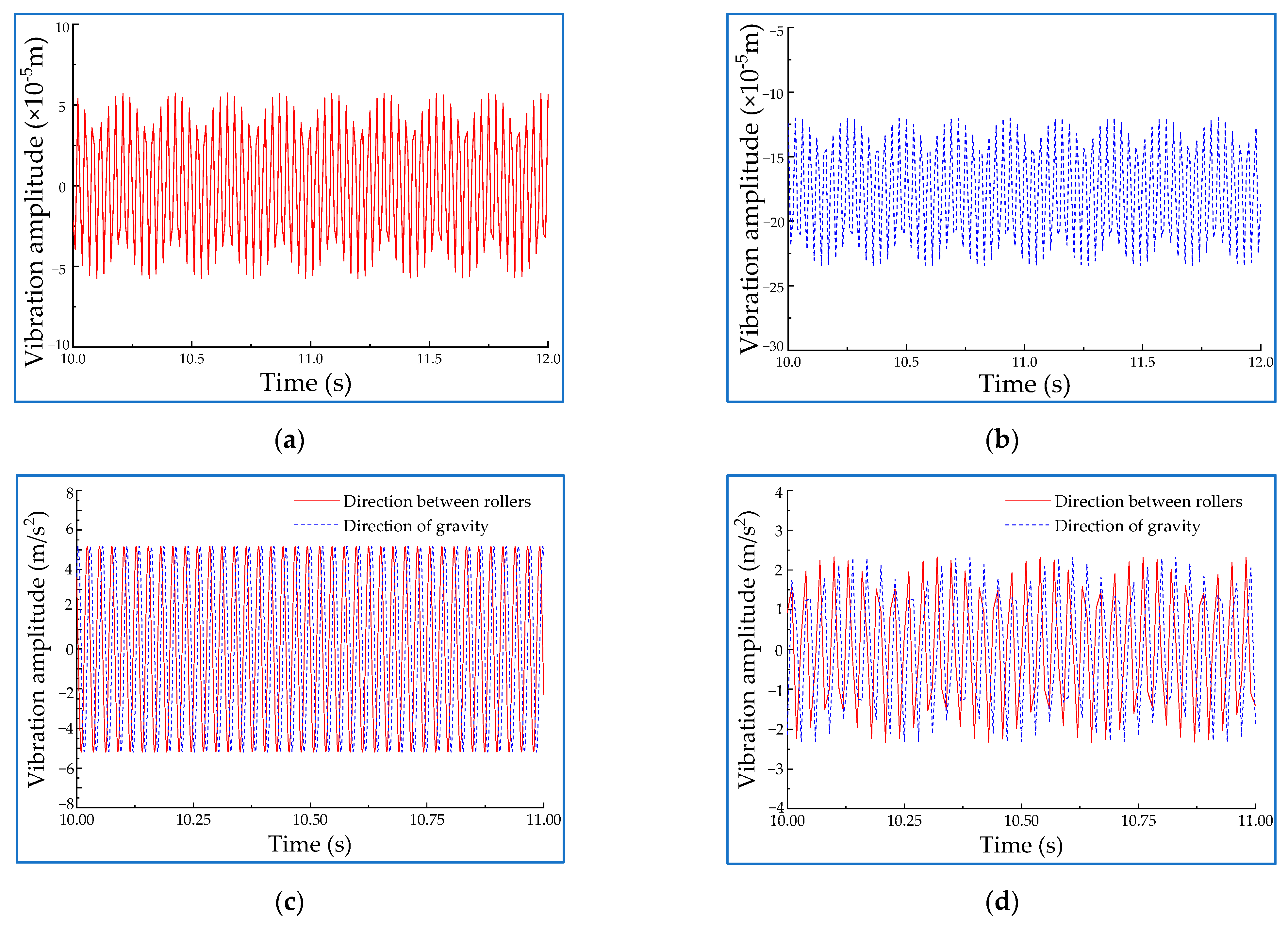
Figure 4.
Simplified model of the roll coating.

Figure 5.
Variation diagram of the meniscus after introducing a small disturbance ε.
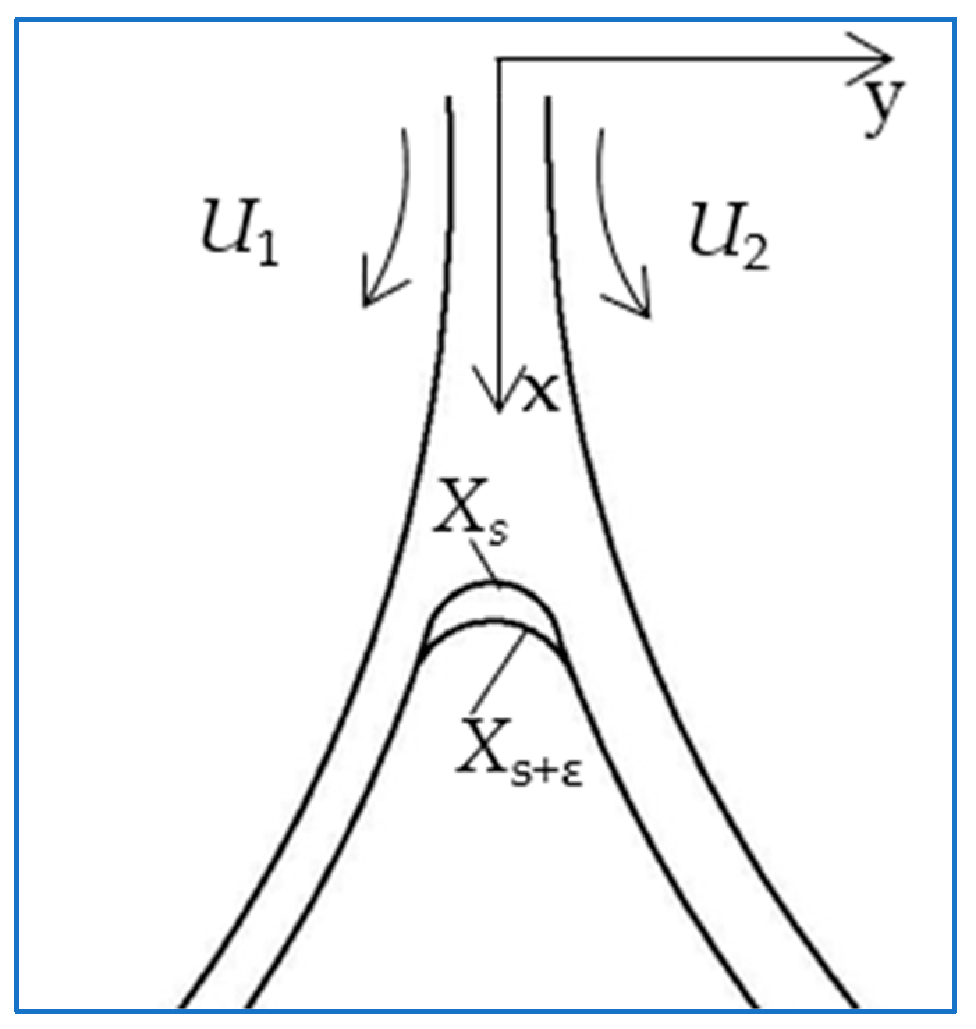
Figure 6.
Two rollers model of roll coating simulation test equipment (1—Drawing roller, 2—coating materials box, 3—Coating liquid, 4—Coating roller).
Figure 6.
Two rollers model of roll coating simulation test equipment (1—Drawing roller, 2—coating materials box, 3—Coating liquid, 4—Coating roller).
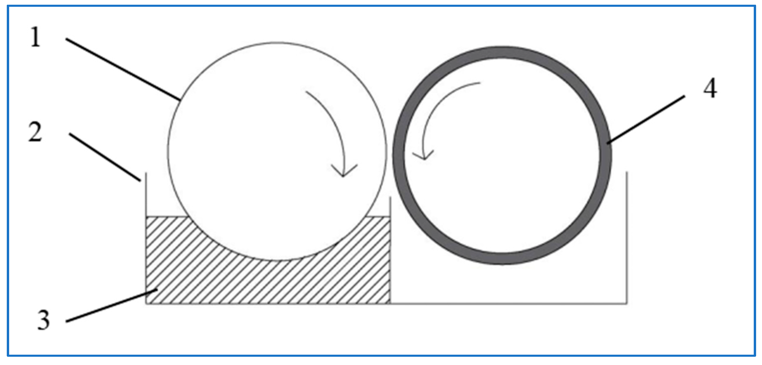
Figure 7.
Contrast diagram of coating thickness affected by vibration.

Figure 8.
Variation chart of coating thickness at different rotational velocities. At (a) 400 rpm; (b) 600 rpm; (c) 800 rpm; and (d) 1000 rpm.
Figure 8.
Variation chart of coating thickness at different rotational velocities. At (a) 400 rpm; (b) 600 rpm; (c) 800 rpm; and (d) 1000 rpm.

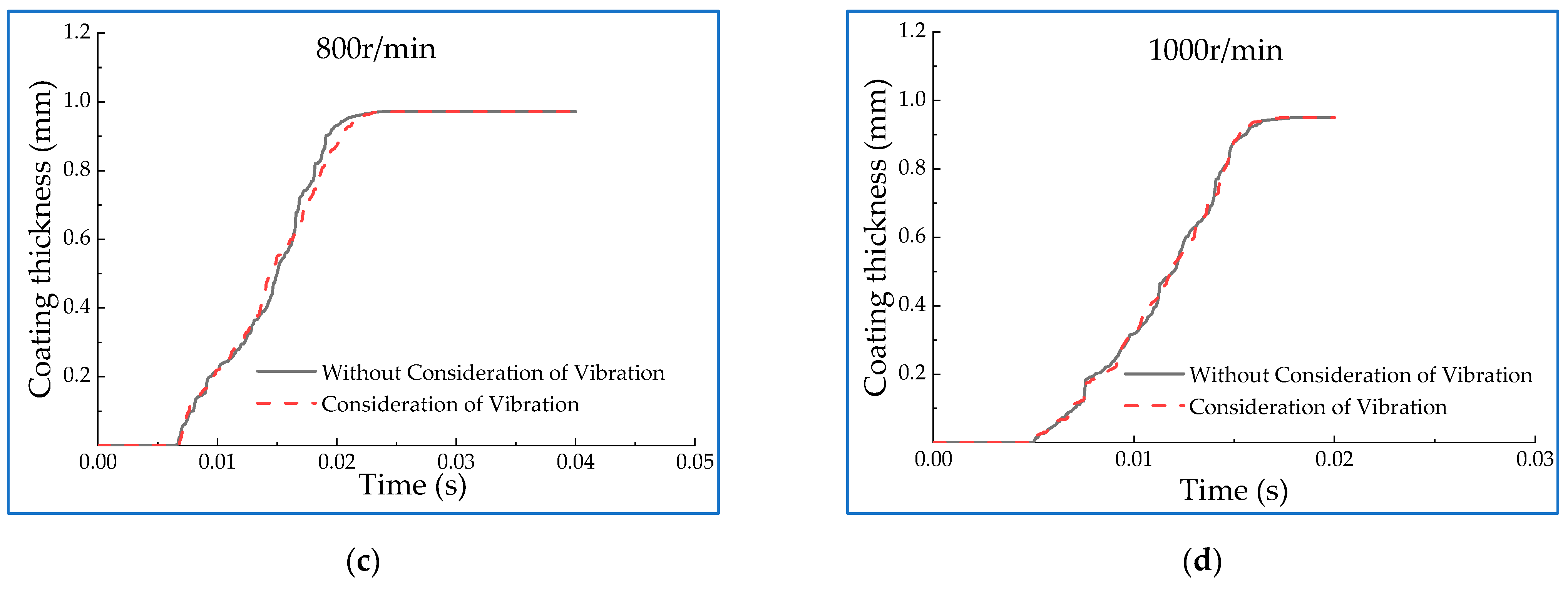
Figure 9.
Variation chart of coating thickness under different coating viscosity. The viscosity values are (a) 1 Pa·s and (b) 1.5 Pa·s.
Figure 9.
Variation chart of coating thickness under different coating viscosity. The viscosity values are (a) 1 Pa·s and (b) 1.5 Pa·s.
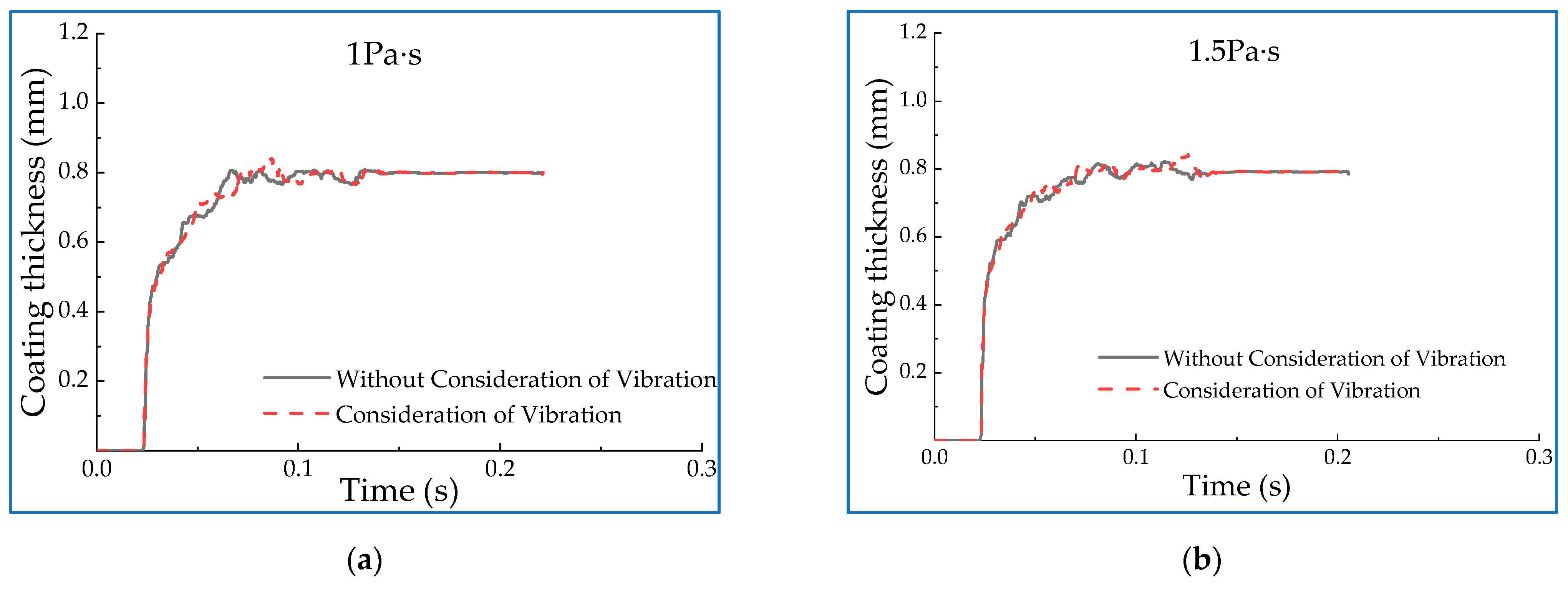
Figure 10.
Variation chart of coating thickness under different distances between rollers. The distances are (a) 1 mm; (b) 1.5 mm; (c) 2.5 mm; and (d) 3 mm.
Figure 10.
Variation chart of coating thickness under different distances between rollers. The distances are (a) 1 mm; (b) 1.5 mm; (c) 2.5 mm; and (d) 3 mm.
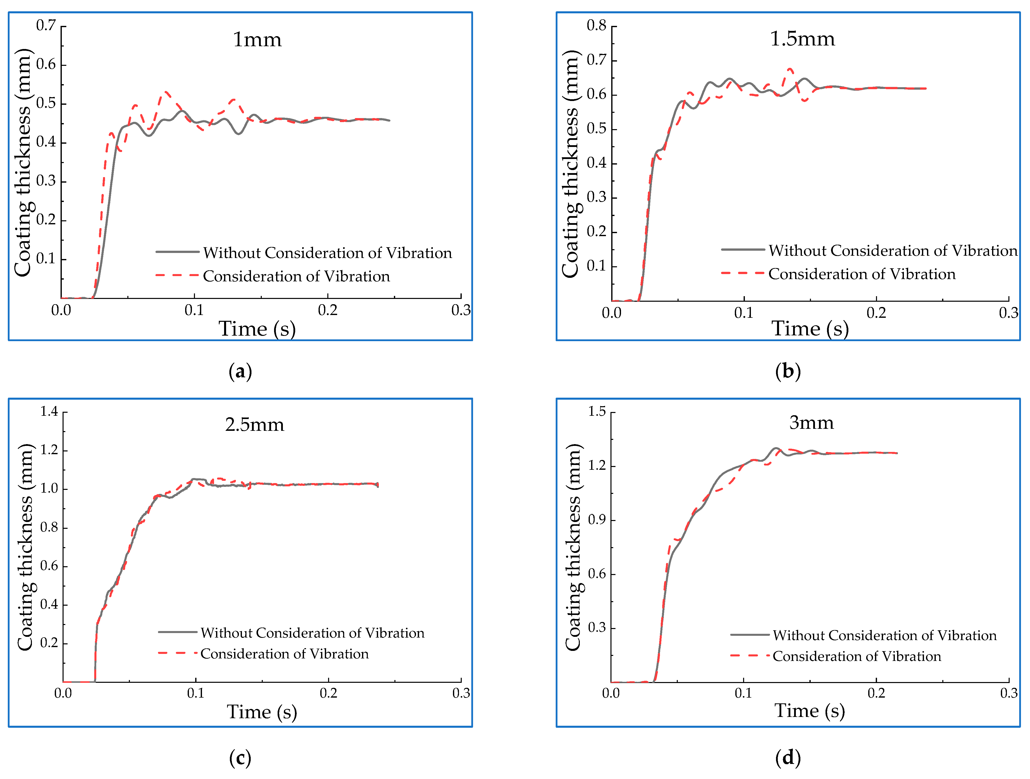
Figure 11.
(a) Construction of vibration experiment platform; (b) The roller-coating operation effect test.
Figure 11.
(a) Construction of vibration experiment platform; (b) The roller-coating operation effect test.
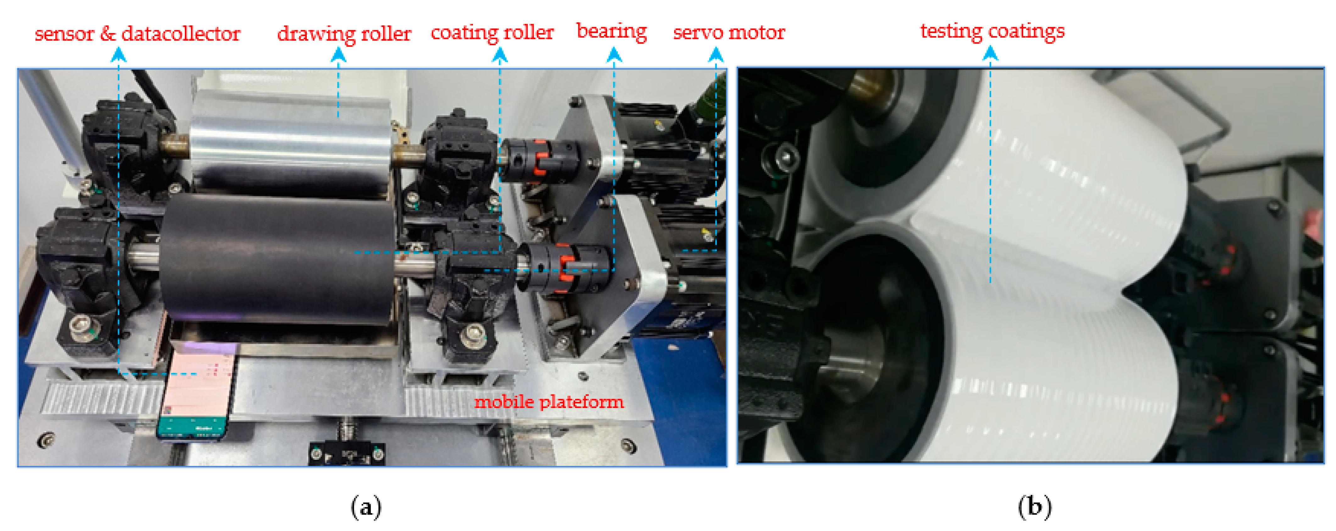
Figure 12.
Vibration acceleration of rotor components at different velocities. The velocity at (a) 200 rpm; (b) 400 rpm; (c) 600 rpm; (d) 800 rpm; and (e) 1000 rpm.
Figure 12.
Vibration acceleration of rotor components at different velocities. The velocity at (a) 200 rpm; (b) 400 rpm; (c) 600 rpm; (d) 800 rpm; and (e) 1000 rpm.

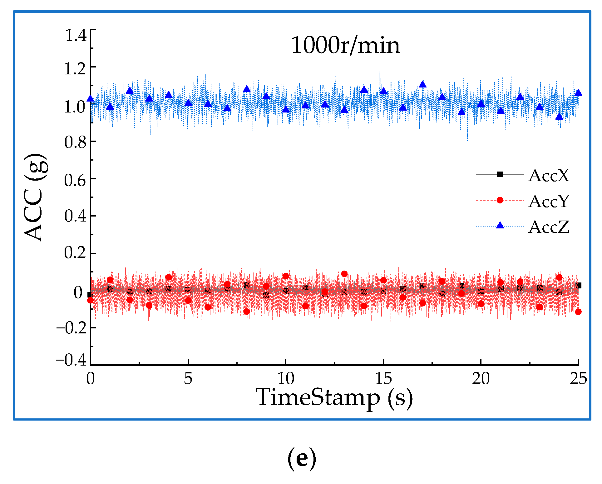
Figure 13.
Comparison of vibration amplitudes in the direction between rollers.
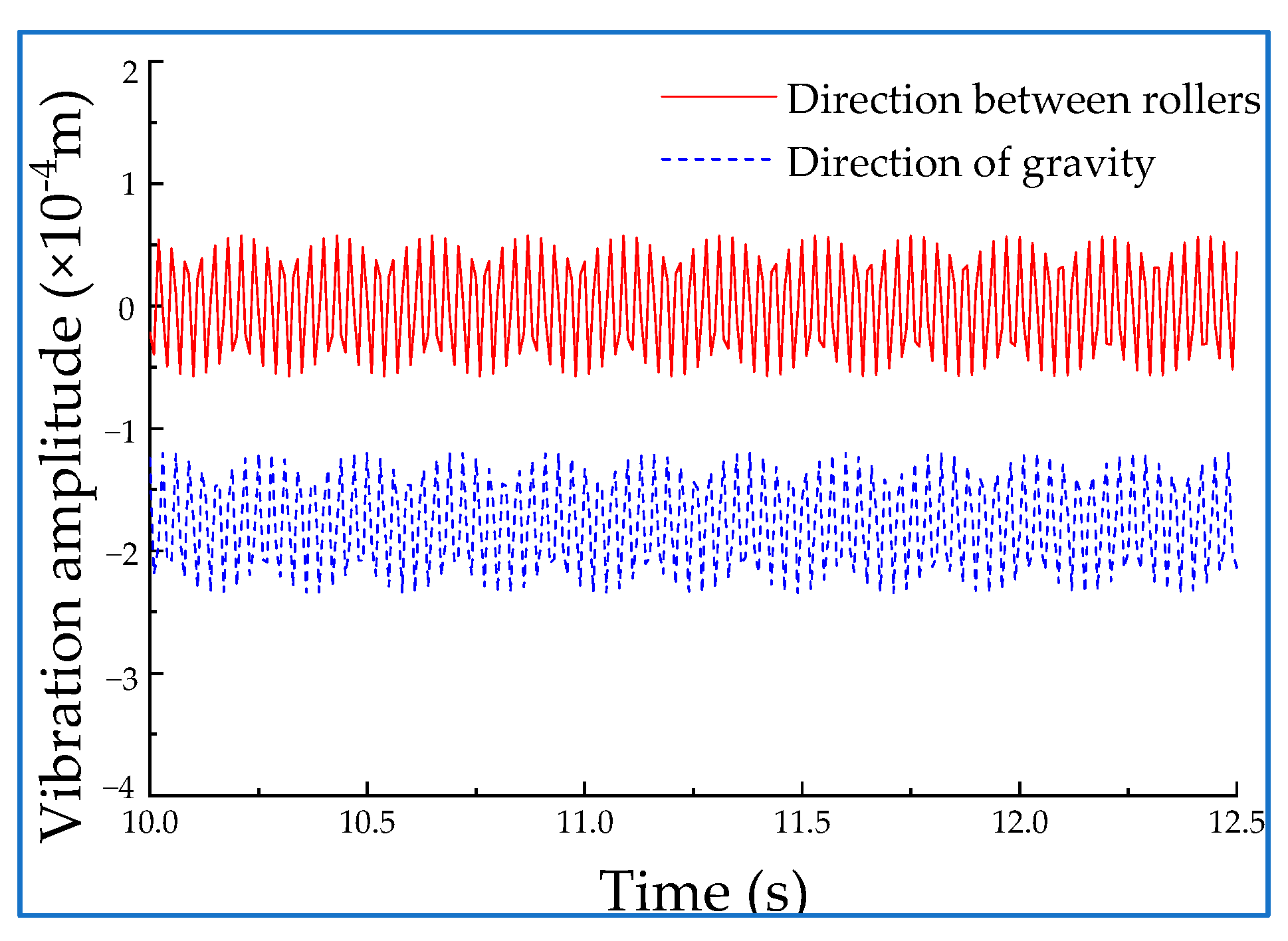
Figure 14.
(a) Comparison of vibration acceleration amplitudes in the direction between rollers. (b) Comparison of vibration acceleration amplitudes in the direction of gravity.
Figure 14.
(a) Comparison of vibration acceleration amplitudes in the direction between rollers. (b) Comparison of vibration acceleration amplitudes in the direction of gravity.


Table 1.
Correlation coefficients of curves under different parameters.
| Rotating Velocity (r/min) | Correlation Coefficient | Viscosity (Pa·s) | Correlation Coefficient | Spacing (mm) | Correlation Coefficient |
|---|---|---|---|---|---|
| 200 | 0.99798 | 0.5 | 0.99798 | 1 | 0.96957 |
| 400 | 0.99854 | 1 | 0.99766 | 1.5 | 0.99323 |
| 600 | 0.99888 | 1.5 | 0.99709 | 2 | 0.99798 |
| 800 | 0.99862 | 2.5 | 0.99818 | ||
| 1000 | 0.99951 | 3 | 0.99895 |
Publisher’s Note: MDPI stays neutral with regard to jurisdictional claims in published maps and institutional affiliations. |
© 2022 by the authors. Licensee MDPI, Basel, Switzerland. This article is an open access article distributed under the terms and conditions of the Creative Commons Attribution (CC BY) license (https://creativecommons.org/licenses/by/4.0/).
Share and Cite
MDPI and ACS Style
Lv, H.; Yang, K.; You, J.; Wang, S. Operational Stability Analysis on the Roller-Coating Process for a Roll Coating-Simulation Test Equipment. Machines 2022, 10, 304. https://doi.org/10.3390/machines10050304
AMA Style
Lv H, Yang K, You J, Wang S. Operational Stability Analysis on the Roller-Coating Process for a Roll Coating-Simulation Test Equipment. Machines. 2022; 10(5):304. https://doi.org/10.3390/machines10050304
Chicago/Turabian StyleLv, Hongzhan, Kehang Yang, Jia You, and Shuyan Wang. 2022. "Operational Stability Analysis on the Roller-Coating Process for a Roll Coating-Simulation Test Equipment" Machines 10, no. 5: 304. https://doi.org/10.3390/machines10050304
Note that from the first issue of 2016, this journal uses article numbers instead of page numbers. See further details here.