
Mitigation of High-Frequency Eddy Current Losses in Hairpin Winding Machines


1
Department of Electromechanical, Systems, and Metal Engineering, Ghent University, 9000 Ghent, Belgium
2
FlandersMake@UGent, Core Lab EEDT-MP, 3001 Leuven, Belgium
3
Department of Electrical Engineering, Faculty of Engineering, Menoufia University, Menoufia 32511, Egypt
4
Department of Electrical Engineering, Kafrelshiekh University, Kafrelshiekh 33511, Egypt
*
Author to whom correspondence should be addressed.
Machines 2022, 10(5), 328; https://doi.org/10.3390/machines10050328
Submission received: 11 April 2022
/
Revised: 27 April 2022
/
Accepted: 28 April 2022
/
Published: 30 April 2022
(This article belongs to the Special Issue Latest Trends in the Design of Hairpin Winding Machines for Transport Electrification Purposes)
Abstract
:In high-speed and high-frequency electric machines, one of the major issues that impacts the performance and capability of a machine is the high-frequency eddy current losses in the windings. This work deals with AC winding losses in flat rectangular conductors. Aiming for eddy current loss mitigation, two different materials are investigated and compared for the same winding design, namely copper and aluminum. Using the finite element method (FEM), the conductor loss and current density behavior are simulated at the strand level. Further, in order to verify the simulated losses, the AC losses are measured and compared over a wide range of frequencies. Finally, recommendations are provided based on the obtained measurements to identify the best winding topology that is most suitable for automotive applications.
1. Introduction
In modern automotive applications, the winding losses are typically the major loss component that limits the output capability [1]. Therefore, manufacturers are paying special attention during the winding design process to overcome this challenge. With the growing demand for high-speed operation, the conductors are exposed to high-frequency alternating flux, leading to high induced eddy currents in the conducting material. This results in nonuniform current density distribution over the conductor cross-section area. Eventually, the winding apparent resistance increases and additional losses are introduced, which are known as AC winding losses [2,3,4]. The mitigation of the AC losses in the windings is a major challenge. This is why many manufacturers have been exploring unconventional smart technologies such as additive manufacturing in order to prototype machine windings with high electromagnetic performance [5].
Hairpin windings have drawn a lot of attention, especially in traction applications. Owing to their high fill factor, flat rectangular conductors have the benefits of high electromagnetic and thermal performance. With the present highly automated manufacturing process, the production of these windings can be simplified. Accordingly, hairpin windings are an attractive option for electrical machines that require high power density and efficiency. The major drawback of such windings is the AC losses due to the significant skin and proximity effects in the sloid conductors. Therefore, mitigation of AC losses in these flat conductors is a key consideration for the design of high-power dense electric machines.
The modeling of AC winding losses is a time-consuming process due to the complex models that must be built. Therefore, the designers of electrical machine typically assume a uniform current density distribution at an early stage. As a result, the machine temperature increases to unplanned levels, and different hotspots are detected during the actual machine operation. This will finally lead to unexpected winding failures.
In order to avoid winding failures, the effect of the eddy current must be inspected, particularly in high-frequency domains. In the literature, different methodologies have been used to estimate the AC winding losses, including analytical [6,7,8], FEM [9,10,11], and hybrid approaches [12,13,14]. The analytical approaches are fast, although the accuracy is not high owing to the approximations in the models. On the other hand, the FEM is relatively accurate but the computational time is extremely high if a complete machine model is considered. With this being said, this research is carried out using the FEM on a reduced machine model in order to achieve high accuracy and fast computation times.
The main objective of this paper is to investigate the AC eddy current losses for machine windings with flat conductors. First, the AC losses are modeled at the strand level at different frequencies. Additionally, different conducting materials are compared—namely copper and aluminum. Additionally, using a special testing approach, the AC losses are measured and compared with the simulated results. A very good match is obtained between both simulations and measurements. Finally, recommendation are provided for the reader to highlight the importance of material selection, especially in high-frequency domains.
2. Winding Simulation at Strand Level
2.1. Types of Eddy Current Losses
There are four types of eddy current losses in electrical machine windings, as shown in Figure 1. This includes the skin effect, proximity effect, eddy current loss due to external field, and circulating current losses. Additionally, the current distributions for both the strand level and bundle level are illustrated, depending on whether the current is closed within a single strand or multiple ones. Basically, the skin effect is the nonuniform distribution of the current density in a conductor due to its own time-varying current. During this phenomenon, the current density is higher near the surface than in the inner part of the conductor. Figure 1(a1,a2) show the current distribution at the strand level and bundle level due to the skin effect. The skin depth is a measure of the current density and the effective depth of the conductor when carrying an AC current, and is defined as the distances from the conductor surface to the point at which the current density falls to 1/e (36.8%) of its value at the outer edge. It can also be expressed as:
where is the conductor resistivity, is the frequency of the current, is the permeability constant of the vacuum, and is the relative permeability of the conductor material.
With a smaller effective cross-section area, the losses due to skin effect will be higher. as expressed in the following equation [15]:
where is the effective cross-section area, is the conductor length, and is the conductor radius.
Regarding the proximity effect, the nonuniform distribution of the conductor current occurs due to currents in the adjacent conductors, as shown in Figure 1b. A third type of loss is the eddy current loss due to the external magnetic field (Figure 1(c1,c2)). One last type of loss is the circulating current loss, which is simply demonstrated in Figure 1 (d1,d2), in which two solid conductors are located inside a slot with the upper conductor facing less area of the ferromagnetic material. If the two conductors are connected in series as in Figure 1(d1), there will be a parasitic eddy current induced in the strand level due to the variation of the flux lines. Furthermore, if these conductors are connected in parallel as in Figure 1(d2), there will be an additional circulating current at the bundle level. The main reason for this current is that the magnetic flux that is linked by the upper conductor is lower than the bottom one, resulting in a voltage difference between the two strands. One of the effective solutions to reduce this circulating current is the transposition of the strands so that each one is exposed to the same level of flux linkage.
2.2. Baseline Machine
Here, a 48-slot and 8-pole interior permanent magnet (IPM) synchronous reluctance machine (SynRM) is proposed, targeting a pure electric vehicle traction application. This design is based on the one used in the 2019 Nissan Leaf electric vehicle (model EM57) [16]. The electrical machine is equipped with a distributed winding and single-strand flat conductors. The machine rated speed is 15,000 rpm, which results in a fundamental frequency of 1 kHz. Additionally, in the flux weakening region, the speed can be increased up to a maximum of 30,000 rpm, resulting in a fundamental frequency of 2 kHz. In order to achieve a high fill factor for the rectangular conductors, the stator slots are designed with a parallel-sided shape. In the rotor, each pole is designed with 3 delta shape interior PMs in order to increase the machine power density. The machine configuration and flux distribution are shown in Figure 2. In the highlighted winding layout, a single-layer configuration is used and the number of slots per pole per phase is 2. Additionally, this slot–magnet pole combination results in a high winding factor of 0.966.
2.3. Two-Slot Model at Strand Level
In order to investigate the performance of the baseline machine at the strand level, a 2-slot motorette is modeled using the FEM. In this model, the 8 turns in each slot are simulated individually to evaluate the losses in each turn, as shown in Figure 3. The cross-slot leakage flux is calculated across a vertical line in the middle of the slot (y-line). As can be seen, the leakage flux increases remarkably as it gets closer to the slot opening. This issue will result in extra eddy current loss, which depends on the location of the strand inside the slot. Eventually, different loss levels between the conductors in the same slots will be introduced, despite carrying the same current at the same frequency.
2.4. Mitigation of Eddy Current Losses in Hairpin Windings
In a single flat conductor with a height of , width of , and active length of , the eddy current losses due to the external AC magnetic field can be expressed as follows [17,18];
where is the flux density of the sinusoidal external field, is the angular frequency, and is the material resistivity. From the above equation, different techniques can be used to reduce the eddy current losses. This can be done via the following steps:
- (i)
- Reducing the conductor height (). However, this method can result in a reduced fill factor and an increased DC resistance component;
- (ii)
- Reducing the external flux density (). This is can be done be leaving a space near the slot opening, so that the upper conductors are less affected by the cross-slot leakage flux. However, using this method will result in a lower coil height, and eventually a lower fill factor;
- (ii)
- Increasing the material resistivity () can also be an effective method to reduce the high-frequency eddy current losses. However, this requires the use of a different conducting material than pure copper, with higher resistivity.
In this paper, the third technique is used because it reduces the high-frequency losses without impacting the winding fill factor. To this end, aluminum is investigated as an alternative material to copper.
2.5. Aluminum as an Alternative to Copper at High Frequency
Beside its high resistivity, aluminum has only 30% of the weight of copper. As a result, the machine power density can be increased significantly, especially at high speeds. Using the 2-slot model, the current density distribution is simulated at the strand level using both copper and aluminum, and the results are compared in Figure 4 at a high frequency of 2 kHz. It can be noticed that both cases have the same increasing pattern of current density, in which the current density is low at the lower conductor and it increases as it gets closer to the slot opening. Under the same current and frequency, the maximum current density is reduced by nearly 40% when using aluminum instead of copper. As a result, the power losses in each turn are reduced significantly, as shown in Figure 5a at 2 kHz. In this figure, it is clear that the top three turns possess over 70% of the total losses. Therefore, using aluminum at this frequency level can be significantly beneficial for damping the eddy current losses.
Finally, the two materials are compared at different frequency levels and the winding losses are shown in Figure 5b. Obviously, the copper coil has lower losses at low frequencies up to nearly 1 kHz. However, above 1 kHz, the aluminum coil starts to show a relatively better performance, which is much better at higher frequency levels. Thus, it can be concluded that the aluminum coil is a better alternative only for high-speed machines with serious eddy current winding losses. However, it can be used in the low-frequency domain if the advantage of the low mass density outweighs the high-resistivity disadvantage.
3. Experimental Verification
Two coils with a flat conductor shape are prototyped using copper and aluminum materials, as shown in Figure 6. Both coils have the same number of turns and the same conductor cross-section. The aluminum coil has only 30% of the weight of the copper one, which means it can significantly improve the machine’s power density.
For a fair comparison, both coils are placed inside the same 2-slot motorette, as shown in Figure 7. This E-shape core is made from laminated silicon steel sheets with open and parallel side slots. This special design results in a high fill factor for both coils of 72.6%. In each coil, two temperature sensors (PT100) are used to detect the temperature at the upper-layer and lower-layer conductors.
Figure 8 shows the test setup used to measure and evaluate the power losses at different frequency levels. The setup consists of a DC power source and AC variable voltage variable frequency source connected to the test sample in series with a power resistor. Additionally, various measurement devices such as a power analyzer and dSpace MicroLabBox 1202 instrument are used for data acquisition. The voltage and current signals are measured using voltage and current probes. The waveforms are also monitored using the dSpace control disc and verified using a digital scope. Additionally, the sample temperature signals are measured using a PT100 amplifier PCB. The temperature is also verified using an external thermal camera next to the coil sample. A 2 kW noninductive resistance is selected to be connected in series so that it does not affect the current sinusoidal waveform. Due to the high test currents, this series resistance is equipped with a powerful heat sink. The resistor specification are listed in detail in the datasheet in [19].
In order to perform the measurements at a defined temperature value, a specially designed cooling jacket is prototyped using an aluminum interface and 3D-printed fixation, as shown in Figure 9a. Both test samples are then assembled with the cooling jacket, as shown in Figure 9b,c. Moreover, a water chiller is used to control the cooling temperature.
The thermal behavior is investigated first at steady state using DC and AC currents for a time period of 5 min. As demonstrated in the thermal images in Figure 10, only the DC current can result in a uniform temperature distribution over the test sample (Figure 10a). On the other hand, when the coil sample carries A high-frequency AC current for a long time period, the temperature distribution is not uniform, even with forced cooling, as shown in Figure 10b,c. With this being said, it can be concluded that performing the AC loss measurement at steady state will not result in a better match between the simulated and measured power losses. Instead, a fast testing method will be an efficient way to perform the AC loss measurements.
This fast testing method is carried out by allowing the current to pass through the sample for only 2 s. In this way, the temperature of the test sample does not increase. Additionally, the main purpose of this fast testing approach is to perform the measurements at a defined uniform temperature. In Figure 11, both samples are tested at a fixed temperature of 25 °C. It can be seen that this temperature is uniform across the entire coil under forced water cooling. In this way, the measured losses can be compared fairly with the values obtained from the simulation.
The first step in the measurements is to measure the DC losses for both coils at a rated current of 25 A and temperature of 25 °C. Then, the AC loss measurement is performed under the same conditions at different frequency levels of up to 2 kHz. The total measured losses are compared for both coils, as shown in Figure 12. As expected, the flat aluminum coil shows lower losses starting from 1 kHz. In order to explain this performance more clearly, the total losses are decomposed into the three main components: DC loss, AC loss, and iron loss. The AC loss component is separated by subtracting both the iron loss and DC loss from the total measured losses. Using a dedicated setup (see Appendix A), the magnetic properties are measured for the laser-cut Si-Fe steel lamination used in the E-core. As a next step, the parameters of the Bertotti formula are obtained from curve fitting of the measured core losses at different frequencies and magnetic flux density peak values. The core loss model is accurate and it considers the manufacturing effects after the cutting process. Finally, as demonstrated in the bar graph in Figure 12, the AC loss component in the flat aluminum coil is clearly lower than its value in the flat copper one, especially at high frequencies. This is the main reason behind the performance superiority of the aluminum at high frequencies.
To verify the measured losses in the winding, the simulation losses are compared with the measured losses, as shown in Figure 13. First, the net winding measured losses are calculated by subtracting the core losses from the total measured losses at each frequency level. The preliminary simulation loss is compared with the net measured loss, as shown in Figure 13. It is clear that the simulation (red dashed line) is lower than the net measured losses. The main reason is that the end winding losses are not included in the initial simulation, causing a large underestimation in the losses. This is why the simulation loss is compensated by replacing the DC losses in the active length with the actual estimated one, which is calculated from the actual wire length and gauge. In this way, the losses in the end winding are taken into account. Finally, it is clear that the match between the compensated simulation results and experimental results is much better.
Finally, the ratio between the AC to DC losses is compared for both coil samples, as shown in Figure 14. Obviously, the AC losses of the flat aluminum coil are remarkably low, especially at high frequency levels. For instance, at 1 kHz, the ratio is reduced from 4.4 in the copper to less than half of this value. Also at 2 kHz, this ratio in the aluminum coil is only 34% of its value in the copper one. To sum up, Table 1 compares the physical and electrical properties for both flat copper and flat aluminum coils. It is clear that the aluminum coil can provide significantly better performance at high frequencies with only 30% of the weight of copper.
4. Conclusions
This paper provides an investigation of the eddy current losses in flat rectangular conductors at the strand level. Using the FEM, the winding domain is divided into single conductors to evaluate the AC losses in each turn. Additionally, copper and aluminum are compared at different frequency levels. In addition to weight and cost savings, aluminum provides a much better electromagnetic performance in the high-frequency domain. Additionally, in order to verify the simulation results, two coils with a flat-shaped conductor are prototyped and tested under the same electric and thermal conditions used in the simulation. The measured results correspond well with those obtained from the simulation. It is finally concluded that the flat aluminum windings are a much better alternative to the copper windings due to their ability to limit the high-frequency eddy currents.
Author Contributions
A.S.; methodology, A.S., M.N.I. and P.S.; software, A.S.; investigation, A.S., M.N.I. and P.S.; resources, A.S., M.N.I. and P.S.; data curation, A.S.; writing—original draft preparation, A.S.; writing—review and editing, M.N.I. and P.S.; visualization, M.N.I. and P.S.; supervision, P.S.; project administration, P.S.; funding acquisition, M.N.I. and P.S. All authors have read and agreed to the published version of the manuscript.
Funding
This research is financially supported by the Research Foundation—Flanders (FWO) in the project (S001721N) entitled Multi-Material Additive Manufacturing for Electrical Machines with increased performance (AM4EM).
Conflicts of Interest
The authors declare no conflict of interest.
Appendix A
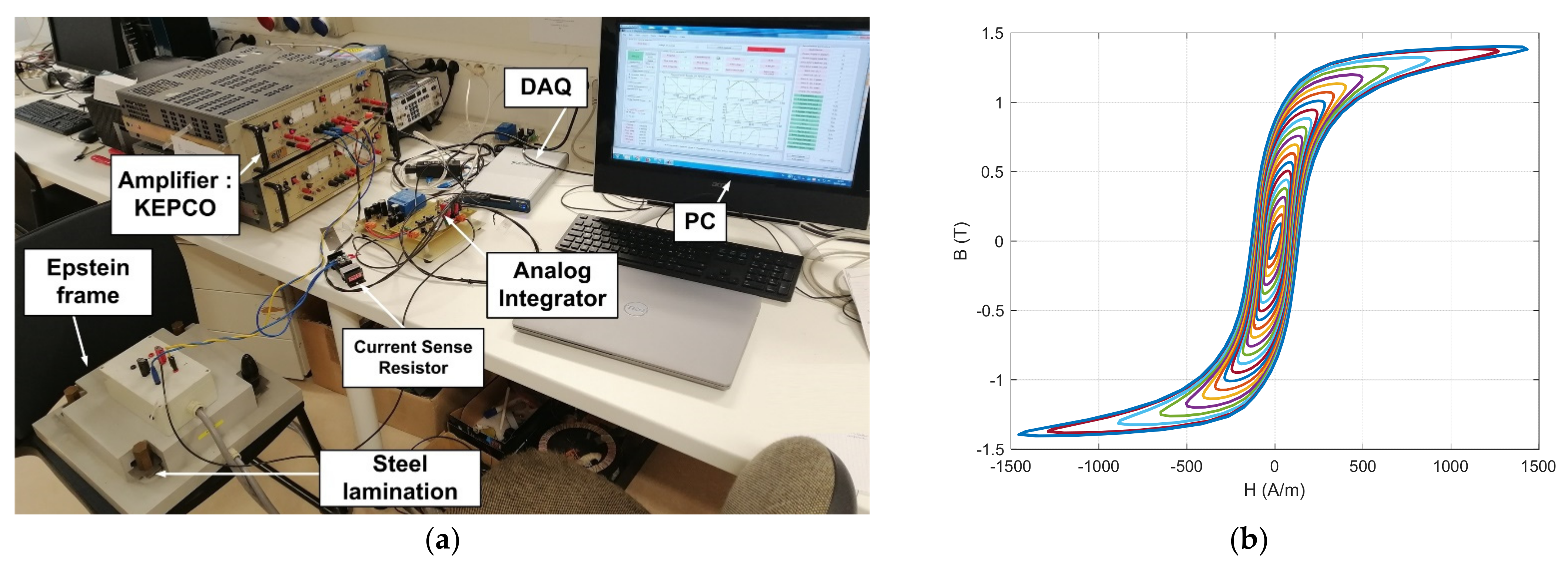
Figure A1 shows the test setup used to measure the magnetic properties of the Si-Fe laminations used in the E-shaped motorette.
Figure A1.
Magnetic material characterization for the Si-Fe lamination used in the E-shaped motorette: (a) test setup using an Epstein frame; (b) measurement sample of the BH loop at 400 Hz.
Figure A1.
Magnetic material characterization for the Si-Fe lamination used in the E-shaped motorette: (a) test setup using an Epstein frame; (b) measurement sample of the BH loop at 400 Hz.
References
- Volpe, G.; Popescu, M.; Marignetti, F.; Goss, J. AC Winding Losses in Automotive Traction E-Machines: A New Hybrid Calculation Method. In Proceedings of the 2019 IEEE International Electric Machines & Drives Conference (IEMDC), San Diego, CA, USA, 12–15 May 2019; pp. 2115–2119. [Google Scholar]
- Selema, A.; Ibrahim, M.N.; Sprangers, R.; Sergeant, P. Effect of Using Different Types of Magnet Wires on the AC Losses of Electrical Machine Windings. In Proceedings of the 2021 IEEE International Electric Machines & Drives Conference (IEMDC), Online, 17–20 May 2021; pp. 1–5. [Google Scholar]
- Silber, S.; Wex, B.; Kaspar, K. Efficient Method for Simulation of AC Losses in Permanent Magnet Synchronous Machines. In Proceedings of the 2020 10th International Electric Drives Production Conference (EDPC), Online, 8–9 December 2020; pp. 1–5. [Google Scholar]
- Zhao, Y.; Li, D.; Pei, T.; Qu, R. Overview of the rectangular wire windings AC electrical machine. CES Trans. Electr. Mach. Syst. 2019, 3, 160–169. [Google Scholar] [CrossRef]
- Selema, A.; Ibrahim, M.N.; Sergeant, P. Metal Additive Manufacturing for Electrical Machines: Technology Review and Latest Advancements. Energies 2022, 15, 1076. [Google Scholar] [CrossRef]
- Bardalai, A.; Zhang, X.; Zou, T.; Gerada, D.; Li, J.; Gerada, C. Comparative Analysis of AC losses with round magnet wire and Litz wire winding of a High-Speed PM Machine. In Proceedings of the 2019 22nd International Conference on Electrical Machines and Systems (ICEMS), Harbin, China, 11–14 August 2019; pp. 1–5. [Google Scholar]
- Selema, A. Development of a Three-Phase Dual-Rotor Magnetless Flux Switching Generator for Low Power Wind Turbines. IEEE Trans. Energy Convers. 2020, 35, 828–836. [Google Scholar] [CrossRef]
- Bardalai, A.; Gerada, D.; Golovanov, D.; Xu, Z.; Zhang, X.; Li, J.; Zhang, H.; Gerada, C. Reduction of Winding AC Losses by Accurate Conductor Placement in High Frequency Electrical Machines. IEEE Trans. Ind. Appl. 2020, 56, 183–193. [Google Scholar] [CrossRef]
- Du, G.; Ye, W.; Zhang, Y.; Wang, L.; Pu, T.; Huang, N. Comprehensive Analysis of the AC Copper Loss for High Speed PM Machine With Form-Wound Windings. IEEE Access 2022, 10, 9036–9047. [Google Scholar] [CrossRef]
- Artetxe, G.; Prieto, B.; Caballero, D.; Elosegui, I.; Martinez Maza, G. A Practical Approach for Estimating Bundle-Level Proximity Losses in AC Machines. IEEE Trans. Ind. Electron. 2021, 1. [Google Scholar] [CrossRef]
- Selema, A.S.; Osheba, D.S.; El-Shanawany, M.M.; Tahoun, S.M. Design and Analysis of a Brushless Three Phase Flux Switching Generator for Aircraft Auxiliary Power Unit. In Proceedings of the 2018 Twentieth International Middle East Power Systems Conference (MEPCON), Cairo, Egypt, 18–20 December 2018; pp. 198–202. [Google Scholar] [CrossRef]
- Xiao, T.; Li, J.; Yang, K.; Lai, J.; Lu, Y. Study on AC Copper Losses in an Air-Cored Axial Flux Permanent Magnet Electrical Machine with Flat Wires. IEEE Trans. Ind. Electron. 2022, 1. [Google Scholar] [CrossRef]
- Tawfiq, K.B.; Selema, A.; Ibrahim, M.N.; Sergeant, P. Synchronous Reluctance Motor Drive System Fed From Three-Phase Matrix Converter. In Proceedings of the 2021 IEEE Industrial Electronics and Applications Conference (IEACon), Online, 22–23 November 2021; pp. 79–84. [Google Scholar]
- Iwasaki, S.; Deodhar, R.P.; Liu, Y.; Pride, A.; Zhu, Z.Q.; Bremner, J.J. Influence of PWM on the Proximity Loss in Permanent-Magnet Brushless AC Machines. IEEE Trans. Ind. Appl. 2009, 45, 1359–1367. [Google Scholar] [CrossRef] [Green Version]
- Moreno, Y.; Almandoz, G.; Egea, A.; Arribas, B.U.A. Analysis of Permanent Magnet Motors in High Frequency—A Review. Appl. Sci. 2021, 11, 6334. [Google Scholar] [CrossRef]
- Evspecifications 2019 Nissan Leaf Specification. Available online: https://www.evspecifications.com/en/model/2bc417 (accessed on 8 April 2022).
- Sullivan, C.R. Computationally efficient winding loss calculation with multiple windings, arbitrary waveforms, and two-dimensional or three-dimensional field geometry. IEEE Trans. Power Electron. 2001, 16, 142–150. [Google Scholar] [CrossRef] [Green Version]
- Mellor, P.; Wrobel, R.; Simpson, N. AC losses in high frequency electrical machine windings formed from large section conductors. In Proceedings of the 2014 IEEE Energy Conversion Congress and Exposition (ECCE), Pittsburg, PA, USA, 14–18 September 2014; pp. 5563–5570. [Google Scholar]
- OHMITE TAP2000—Ultra High Power Planar Resistor. Available online: https://www.ohmite.com/assets/docs/res_tap2k.pdf?r=false (accessed on 8 April 2022).
Figure 1.
Different types of eddy current losses at the strand level and bundle level: (a1,a2) skin effect losses; (b1,b2) proximity effect losses; (c1,c2) eddy current losses due to the external field; (d1,d2) circulating currents losses in series- and parallel-connected conductors.
Figure 1.
Different types of eddy current losses at the strand level and bundle level: (a1,a2) skin effect losses; (b1,b2) proximity effect losses; (c1,c2) eddy current losses due to the external field; (d1,d2) circulating currents losses in series- and parallel-connected conductors.

Figure 2.
Baseline machine: 110 kW SynRM and winding configuration with FEM analysis at rated power (2019 Nissan Leaf—model EM57).
Figure 2.
Baseline machine: 110 kW SynRM and winding configuration with FEM analysis at rated power (2019 Nissan Leaf—model EM57).
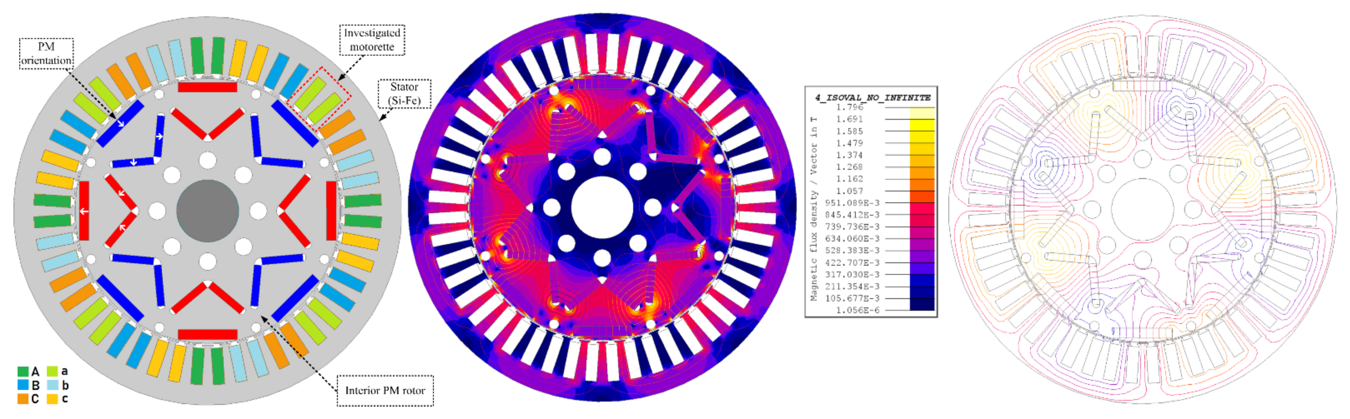
Figure 3.
Figure 3. Modeling of a two-slot motorette at the strand level and estimation of the cross-slot leakage flux at high frequencies.
Figure 3.
Figure 3. Modeling of a two-slot motorette at the strand level and estimation of the cross-slot leakage flux at high frequencies.

Figure 4.
Comparison between current density distributions using copper and aluminum materials at 2 kHz.
Figure 4.
Comparison between current density distributions using copper and aluminum materials at 2 kHz.

Figure 5.
Comparison between flat copper and flat aluminum coils: (a) power loss in each turn at 2 kHz; (b) total power at different frequency levels.
Figure 5.
Comparison between flat copper and flat aluminum coils: (a) power loss in each turn at 2 kHz; (b) total power at different frequency levels.
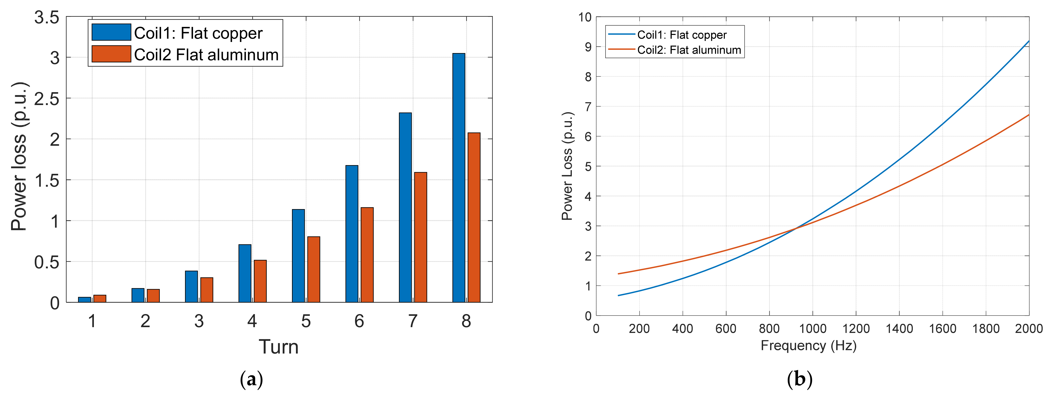
Figure 6.
Copper and aluminum test samples and weight comparison.
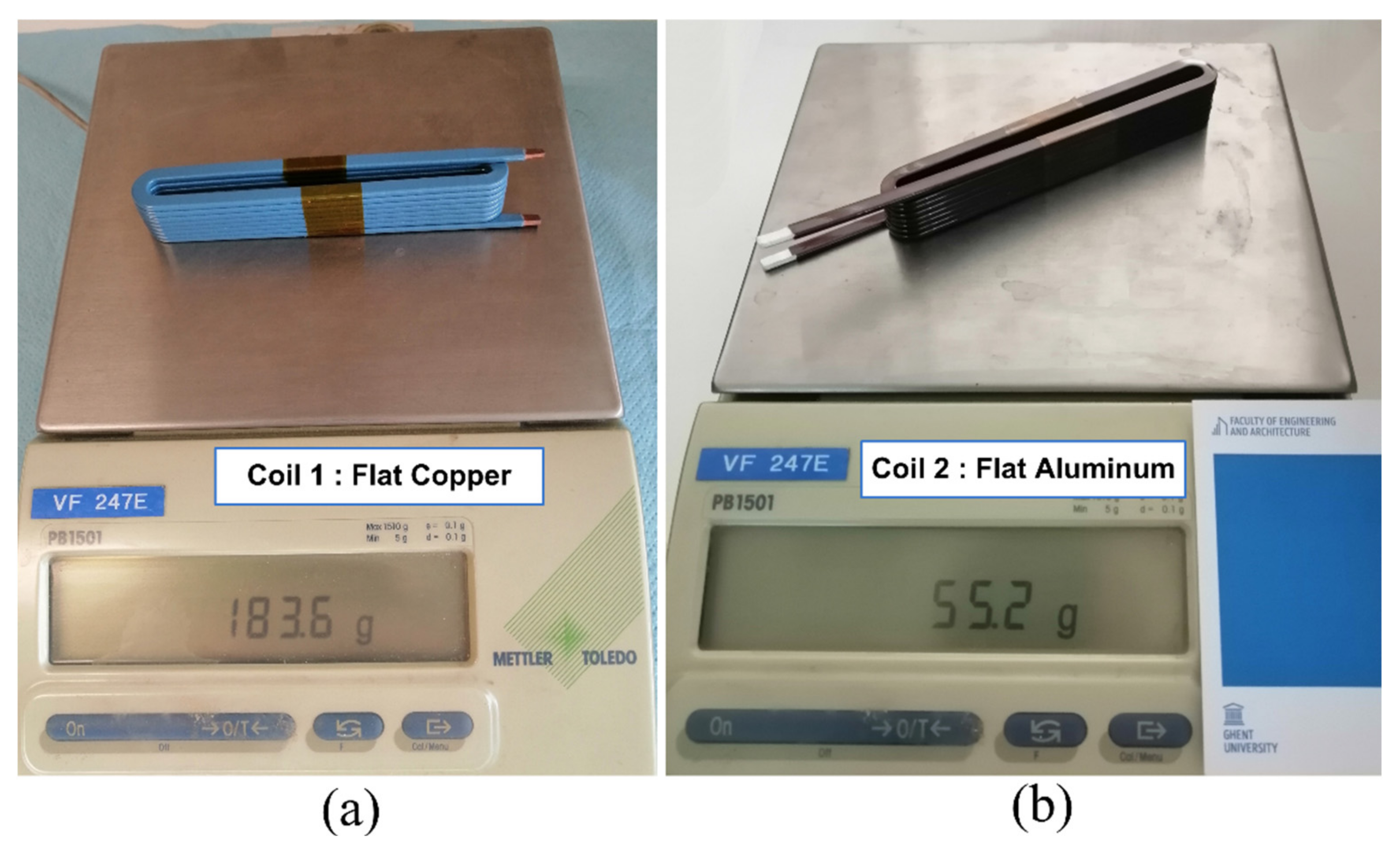
Figure 7.
Assembly of the test samples with the 2-slot motorette: (a) flat copper coil; (b) flat aluminum coil.
Figure 7.
Assembly of the test samples with the 2-slot motorette: (a) flat copper coil; (b) flat aluminum coil.
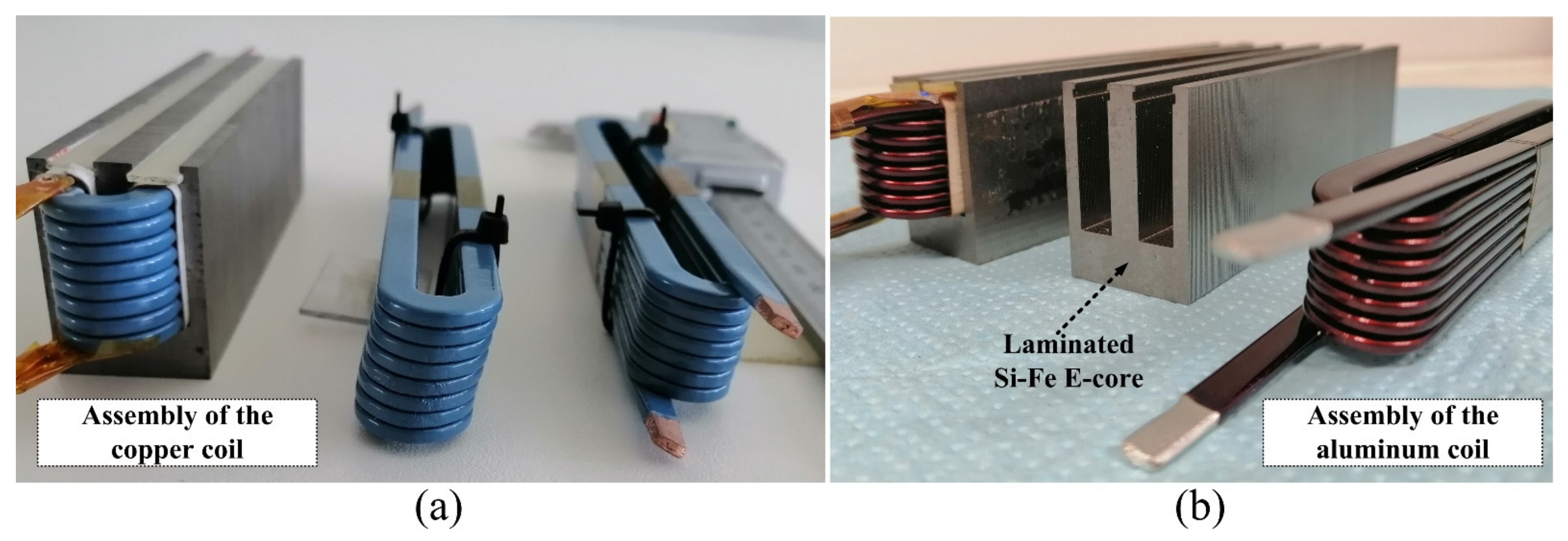
Figure 8.
Photograph of the complete test setup.
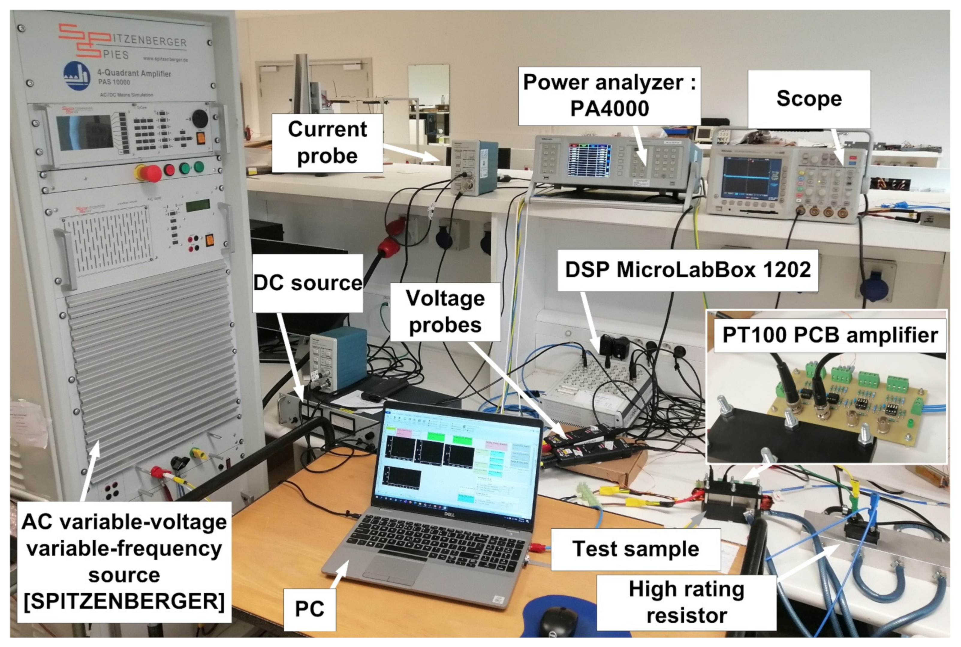
Figure 9.
Cooling jacket used to control the sample temperature: (a) cooling jacket components; (b) assembly with a flat copper coil; (c) assembly with a flat aluminum coil.
Figure 9.
Cooling jacket used to control the sample temperature: (a) cooling jacket components; (b) assembly with a flat copper coil; (c) assembly with a flat aluminum coil.
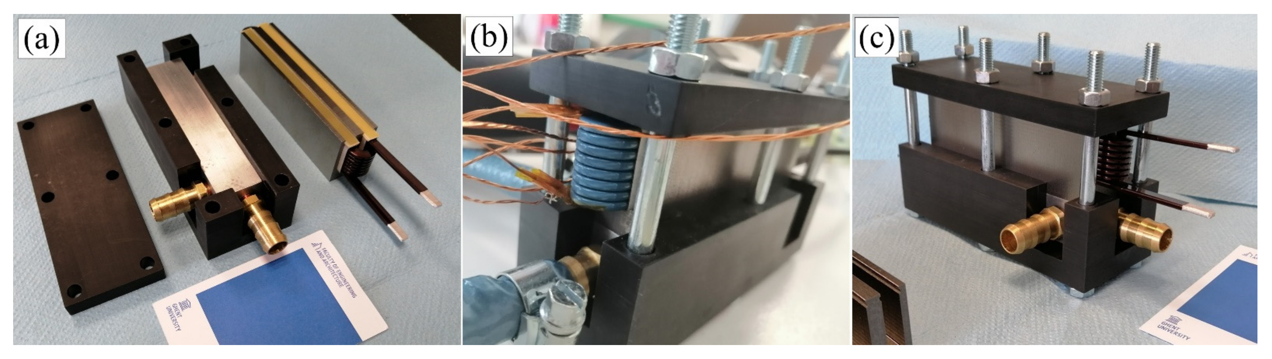
Figure 10.
Thermal behavior of the test samples under steady-state currents: (a) DC excitation without cooling—uniform temperature; (b) AC excitation without cooling—nonuniform temperature; (c) AC excitation with forced cooling—nonuniform temperature.
Figure 10.
Thermal behavior of the test samples under steady-state currents: (a) DC excitation without cooling—uniform temperature; (b) AC excitation without cooling—nonuniform temperature; (c) AC excitation with forced cooling—nonuniform temperature.

Figure 11.
Fast testing approach under forced water cooling at a uniform temperature of 25 °C.
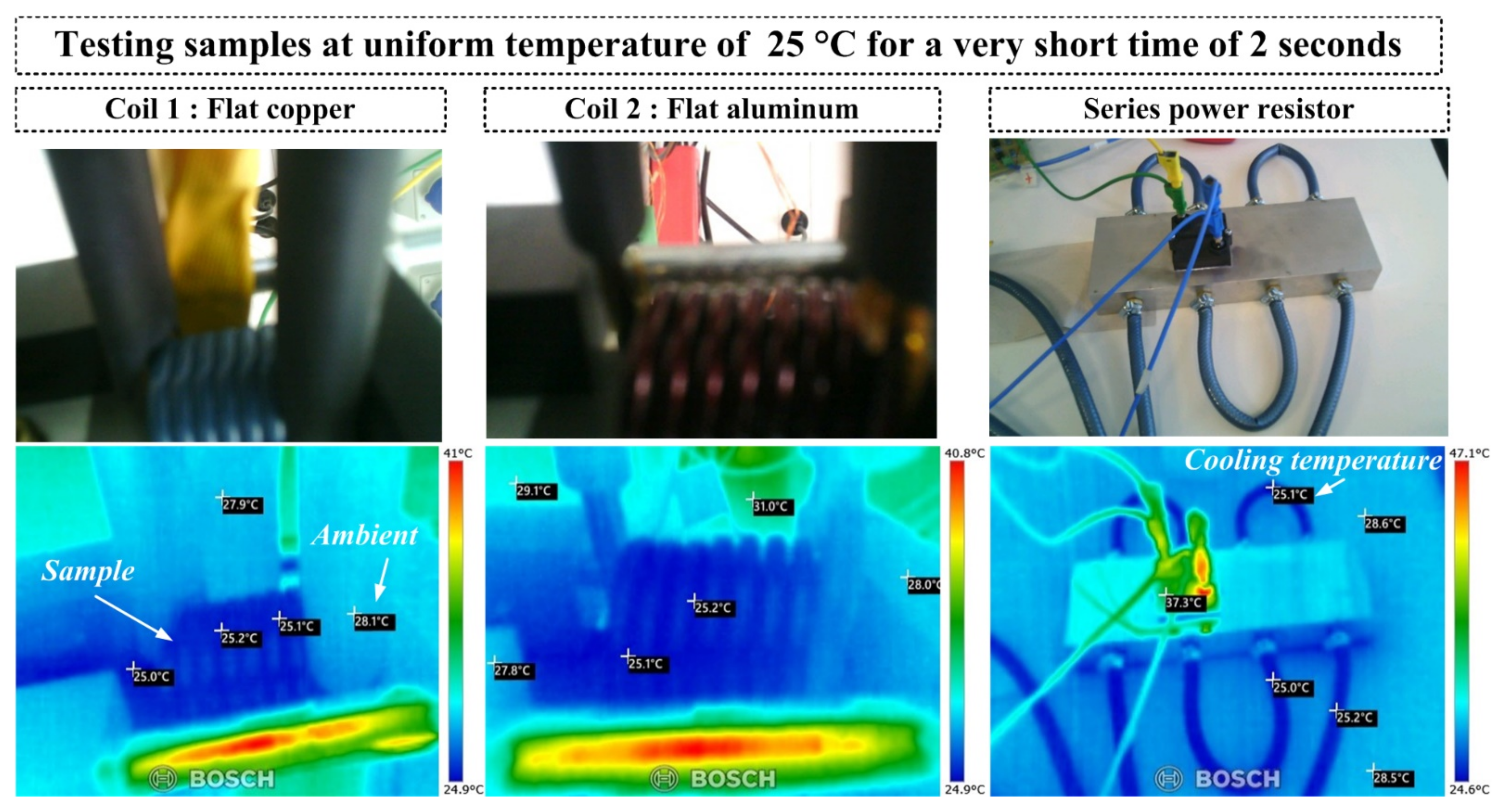
Figure 12.
Total measured loss and its components at different frequency levels at 25 °C.

Figure 13.
Comparison between simulations and measurements for both test samples.
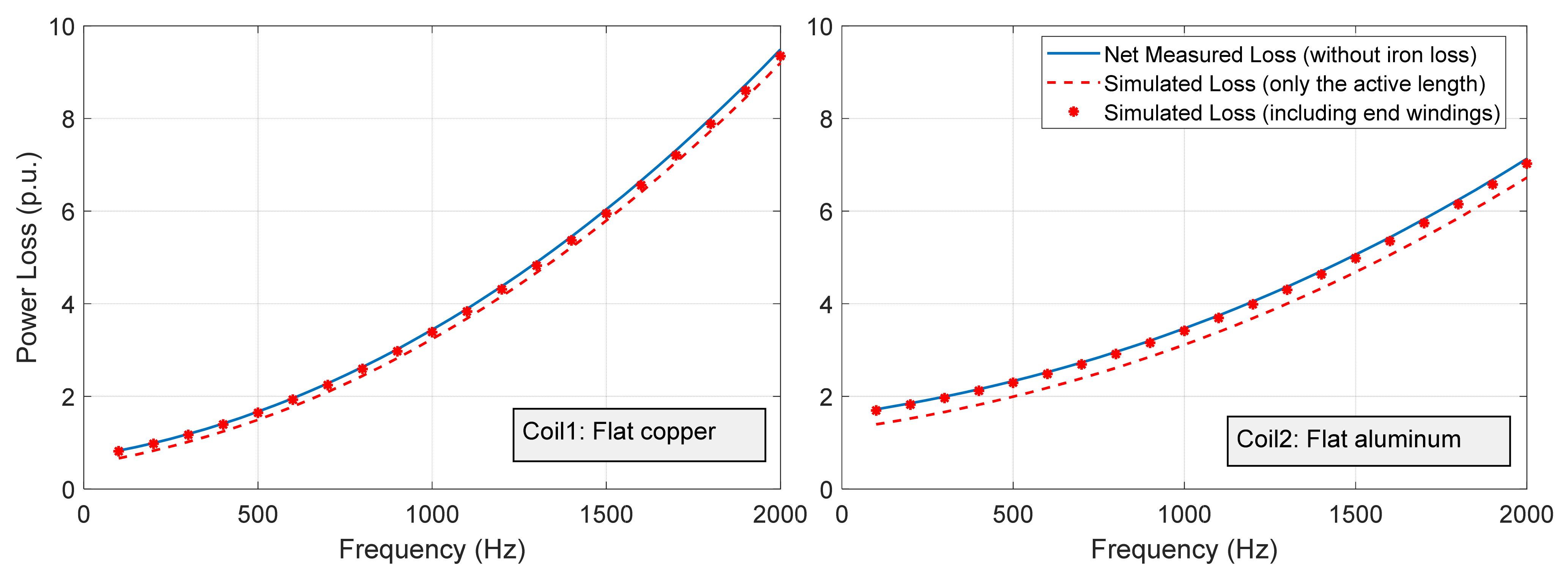
Figure 14.
The ratio between the AC to DC losses at different frequency levels.


Table 1.
Comparison between the copper and aluminum flat coils.
| Coil 1 | Coil 2 | |
|---|---|---|
| Type | Flat copper | Flat aluminum |
| Mass density | 8.96 gm/cm3 | 2.7 g/cm3 |
| Coil Weight | 183.6 gm | 55.2 gm |
| Fill factor | 72.6% | 72.6% |
| Resistance Temper. Coeff. | 0.00393 /K | 0.00410 /K |
| Total losses @ 2 kHz | 12.1 p.u. | 9.77 p.u. |
| Loss ratio (AC to DC) @ 2 kHz | 14 | 4.79 |
| Preferable frequency range | Up to 1 kHz | Above 1 kHz |
Publisher’s Note: MDPI stays neutral with regard to jurisdictional claims in published maps and institutional affiliations. |
© 2022 by the authors. Licensee MDPI, Basel, Switzerland. This article is an open access article distributed under the terms and conditions of the Creative Commons Attribution (CC BY) license (https://creativecommons.org/licenses/by/4.0/).
Share and Cite
MDPI and ACS Style
Selema, A.; Ibrahim, M.N.; Sergeant, P. Mitigation of High-Frequency Eddy Current Losses in Hairpin Winding Machines. Machines 2022, 10, 328. https://doi.org/10.3390/machines10050328
AMA Style
Selema A, Ibrahim MN, Sergeant P. Mitigation of High-Frequency Eddy Current Losses in Hairpin Winding Machines. Machines. 2022; 10(5):328. https://doi.org/10.3390/machines10050328
Chicago/Turabian StyleSelema, Ahmed, Mohamed N. Ibrahim, and Peter Sergeant. 2022. "Mitigation of High-Frequency Eddy Current Losses in Hairpin Winding Machines" Machines 10, no. 5: 328. https://doi.org/10.3390/machines10050328
Note that from the first issue of 2016, this journal uses article numbers instead of page numbers. See further details here.