
Quantitative Expression of a Slight Deviation of the Impact Angle in a Collision Atomizer
1
Centre of Ultra-Precision Optoelectronic Instrument Engineering, Harbin Institute of Technology, Harbin 150080, China
2
Key Lab of Ultra-Precision Intelligent Instrumentation, Harbin Institute of Technology, Ministry of Industry and Information Technology, Harbin 150080, China
*
Author to whom correspondence should be addressed.
Machines 2022, 10(9), 771; https://doi.org/10.3390/machines10090771
Submission received: 8 August 2022
/
Revised: 31 August 2022
/
Accepted: 3 September 2022
/
Published: 5 September 2022
Abstract
:In the processing of colliding atomizers, a small change in the inclination of each orifice will double the impact angle, seriously affecting its atomization performance. In this paper, the influence of slight impact angle deviation on atomization performance was studied in steps of 1°, quantitatively, for the first time. The cavitation effect of the flow field was combined with the shape and parameters of the atomization field. FLUENT was used to simulate the internal flow field, and an independently designed atomizer with transparent nozzles was used to detect the internal flow field in real time. The collision atomization experimental platform and the laser interference particle measurement platform were built independently, and the collision angle was adjusted through a high-precision rotating table to establish the relationship between collision-angle deviation (60° ± 5°) and the atomization field performance (Sauter mean diameter, atomization cone angle, and spatial distribution of droplets). The experimental results showed that under the same injection pressure, the increase in the collision angle led to an decrease in the Sauter mean diameter and an increase in the atomization cone angle. Taking 60° as the benchmark, the particle size distribution was concentrated at ~150 μm to 300 μm within the variation range of ±2°, and the peak positions were very similar.
1. Introduction
In the spray combustion process of a liquid rocket engine, the atomization process of the propellant has a significant impact on the combustion efficiency and the combustion stability of the engine [1]. The atomization results that are produced by the injector play a leading role in the subsequent combustion sub-processes (evaporation, mixing, and chemical reaction) to a certain extent, and the quality of the atomization also directly determines the heat transfer characteristics of the combustion chamber wall. The study of the atomization characteristics of the injection unit has great significance for engine design [2].
The impact nozzle applies the mutual impact of two jets to generate the atomization mixing process, which has the advantages of a simple and compact structure, easy processing, and high atomization mixing efficiency [3,4,5,6,7] The atomization mixing process is widely used in liquid rocket engines [8]. Many studies have been carried out on the impact injector, and a relatively full understanding of its atomization mechanism [9,10,11,12] and atomization characteristics [13,14,15] has been obtained. In atomization research over the years, the droplet diameter, the spatial distribution, and the atomization cone angle in the atomization field are the parameters that have been primarily evaluated and referenced. Researchers have investigated the process of atomization through the formation and fragmentation of liquid film, as well as via the specific parameters that affect atomization, such as injection pressure, nozzle structure, and the characteristics of the liquid working medium. However, there are still frequent problems in the liquid rocket engines that use this injector, most of which are related to the characteristics of atomization and mixing. Accordingly, additional detailed work is needed in assessing the characteristics of atomization and mixing.
Due to the insufficient strength and rigidity of the nozzle processing tool, existing processing technology cannot produce a completely ideal nozzle. In mass production, particularly, there must be various types and sizes of processing deviations in the nozzles. In the context of machining accuracy, the inclination angle of the two nozzles cannot be guaranteed to be a certain value, resulting in slight differences in the collision angle. The generation of collision-angle deviation has a great influence on the performance of the engine. Because the collision nozzles in the injection disc exist in pairs, if collision-angle deviation is common, it cannot be guaranteed that the collision positions are in the same plane. This directly affects the accuracy of the ignition point and combustion efficiency.
Independent research on the impact of collision-angle deviation on the internal flow and the atomization field is required to provide a reference for nozzle processing and manufacturing, to strictly control the maximum deviation and other tolerable deviations that have an impact, to improve the efficiency of nozzle production, and to reduce processing costs. Combined with the corresponding deviation analysis, nozzles can be screened and optimized to achieve the required distribution of the atomized droplets, mass distribution, and velocity distribution, to ensure the reliability and stability of liquid rocket engines.
A current survey of the relevant indicates that there are few studies on the influence of collision-angle deviation on the atomization characteristics of the impingement nozzle, and the research has focused on the influence of larger deviations. Xia et al. [16] used optical technology to study the effects of different critical conditions (sub/trans/supercritical) and collision angles (60°, 90°, 120°, 150°) on the collision process of twin-spray in the double ejector. They analyzed the structure, spatial distribution, and edge characteristics of spray after collision to characterize the collision of the droplets. When the collision angle was 150 degrees, subcritical conditions often led to an off-axis collision. Wang et al. [17] investigated the effect of different impingement angles, nozzle diameters, and injection pressures on the atomization properties of ADN/water-based gel propellants by taking spray images with a double-strand impact nozzle. They found that an increase in the impact angle resulted in a decrease in the rupture length of the liquid film and an increase in the spray cone angle. Sunol and González-Cinca [18] carried out experiments and analysis on the collision of liquid jets in microgravity and focused on the impact of the jets at different impact angles and velocities at low Weber numbers (the ratio of inertia force to surface tension effect). The jets’ impact angles ranged from 6° (quasi-parallel jet) to 180° (frontal impact). According to the impact angles and Weber numbers, an observation state diagram was proposed. At present, except for the study by Cui et al. [19] on aperture deviation, there has been little research on the influence of the microdeviation of collision atomization on the atomization effect. The current simulation and experimental research usually pre-sets the collision angle of the nozzle as a fixed value, and the microdeviation of the nozzle caused by machining error or wear is completely ignored. However, in mass production, these slight deviations are almost unavoidable and imperceptible, with a major impact on the atomization of the fuel and the combustion efficiency. In general, for collision atomization, there is a lack of research on the impact of the slight deviations in the collision angle on the collision atomization effect, which limits improvements in the collision atomization effect and fuel combustion efficiency.
In this study, the influence of a slight deviation of the double-jet collision angle on the atomization characteristics of the atomization field and the sensitivity of the atomization field to its response are analyzed experimentally. A self-designed transparent nozzle is applied to achieve the visualization of the internal flow field, and the cavitation phenomenon of the internal flow field and the atomization effect of the atomization field are comprehensively analyzed. This article focuses on the state of the internal flow field, the atomization cone angle, the Sauter Mean Diameter (SMD), and the spatial distribution of the atomization particle size.
2. Theoretical Background
2.1. Impact Nozzle Atomization Mechanism
The liquid is sprayed from a small-bore colliding nozzle through high pressure to form the impact atomization of two jets. In the process of collision atomization, after the two liquids in the collision nozzles are ejected under pressure, they collide at a certain collision angle, forming an elliptical liquid film at a position perpendicular to the plane of the two jets, as shown in Figure 1. Nozzle atomization can be divided into three areas: the impact wave and liquid fan formation area, the liquid film and liquid filament atomization area, and the droplet secondary atomization and complete atomization area.
After the two high-speed jets collide, they stagnate at the intersection of the jet axes, forming a high-pressure area, and a high-amplitude impact wave appears near the impact area. The impact wave promotes the mixing of the propellant, and the characteristic length is comparable to the jet diameter. It propagates downstream from the liquid film at a speed similar to the jet’s velocity, and dominates the spray fan to generate sinusoidal pulsation, which is the main reason for combustion instability.
The high pressure generated by the impact forces the impact fan to expand laterally to form a liquid film. The liquid film is broken into liquid strips and liquid filaments under the action of surface tension and disturbance force, and the liquid strips and liquid filaments are further broken into droplets. Taylor [20] described the process of liquid film formation by impinging jets with similar dynamics and symmetry under low Weber number and low pressure. He concluded that the balance of the surface tension and the inertial force of the liquid film controlled the breakup of the liquid film. When the relative velocity between the liquid film and the outside airflow increased, the fluctuations caused the liquid film to break up. Under the combined action of the surface tension and external aerodynamic forces, the liquid filaments produced the breaking of the filaments and the peeling of the edge droplets. The droplets were affected by a combination of surface tension, density, viscosity, and ambient airflow. Atomization was completed when the liquid droplets and the surrounding gas flow field reached dynamic equilibrium.
2.2. The Mechanism of the Cavitation Effect
For the same pipe or nozzle, with an increase in injection pressure or speed, the flow of liquid presents five different states. When the pressure at any point is higher than the saturated vapor pressure, the flow is a typical turbulent pipe flow, and the liquid in the high-pressure chamber upstream from the nozzle hole flows into the nozzle hole with a smooth streamline. The separation occurs at the inlet due to the constriction of the fluid channel, forming a localized vortex region. After the vortex zone, the fluid re-attaches to the wall and forms a boundary layer, the thickness of which gradually increases in the downstream direction. After approximately 40 apertures, the flow becomes a fully developed turbulent tube flow, as shown in Figure 2. Figure 3 shows the different cavitation states of the internal flow field.
When the flow rate increases to the point where a low-pressure area, with a pressure equal to the saturated vapor pressure, appears in the tube, bubbles begin to be generated behind the minimum effective flow channel section in the vortex area, thereby forming a local cavitation flow. The bubbles have the characteristics of growing from small to large and converging. When the bubbles are generated, they gather together, separate from the fluid, and converge in the low-pressure area. Several small bubbles may slowly form a large bubble, which slowly forms a layer of bubbles on the wall of the nozzle, and the fluid flows like a boundary layer on the edge of the bubble layer, as shown in Figure 3a.
If the flow rate continues to increase, the minimum pressure in the tube can only be maintained at the saturated vapor pressure and cannot be further reduced, due to the formation of cavitation. The consequence is that more bubbles are generated, so that the cavitation area continues to extend downward until it reaches the outlet of the nozzle, which is the supercavitation or full-cavitation fluid state, as shown in Figure 3b.
For supercavitating flow, when the jet velocity is high and the nozzle is short, a new flow regime, hydraulic flip flow, occurs. The air at the downstream periphery of the nozzle enters the nozzle and the cavitation areas converge, so that the cavitation disappears and is replaced by a thin layer of gas attached to the pipe wall, as shown in Figure 3c. The inner flow field is narrowed and the discharge coefficient (the mass flow rate of the fluid passing through the orifice per unit time at constant pressure) is obviously reduced.
The long nozzle or the uneven upstream flow field makes it difficult for the formed fringe to maintain a stable axisymmetric shape, and local reattachment of the liquid occurs. Correspondingly, the local cavitation area is restored in the tube, which is called partial local hydraulic flip or partial reattachment flow, as shown in Figure 3d.
The evaluation of the cavitation state depends on the critical pressure that is required to change it. The cavitation of the nozzle directly affects the state of the jet and has a significant effect on the stability of the jet and the atomization performance. The initial stage of the cavitation effect and the hydraulic flip stage are two important demarcation lines, which can distinguish the state of the jet as stable or unstable, according to the corresponding critical pressure.
The parameters that reflect the cavitation effect are the discharge coefficient Cd and the cavitation coefficient K, which are expressed as follows:
where A stands for the cross section of orifice (cm2), stands for the mass flow (g/s), and Pin, Pv, and Pout are the injection pressure, saturated vapor pressure, and ambient pressure, respectively (KPa).
The cavitation coefficient reflects whether the difference between the pressure inside and outside the nozzle reaches the saturated vapor pressure. The smaller the cavitation coefficient, the more favorable the cavitation, and the larger the cavitation area.
3. Experimental Setup and Measurement Strategy
3.1. Experimental Setup
The schematic diagram of the overall experimental device of the collision nozzle is shown in Figure 4, including three subsystems: the external input system, the collision atomization system, and the image acquisition system. In the external input system, high-pressure nitrogen gas is input into the sealed liquid storage tank from a nitrogen bottle, and the output pressure of 0 MPa to –1.0 MPa can be achieved by adjusting the pressure sensor. The pressure value and flow value of the entire fluid channel are measured in real time by the pressure sensor and the flow sensor of the main flow channel. In the two tributaries, flow sensors were used to monitor the flow value of the tributaries in real time, and filters were installed to purify the water. The pressure sensor (~0 MPa to 1.0 MPa) used in the experiment can achieve a measurement accuracy of 0.25% of the full scale, and the flow sensor (~1.5 L/h to 100 L/h) can achieve a measurement accuracy of ±0.5% of the full scale.
For the collision atomization system, this research adopted a self-designed collision atomizer, which can realize the replacement of the nozzle and the adjustment of the collision angle. The collision atomizer consists of two symmetrical single atomizers. When the diameter of the jet is small, the angle adjustment system of the jet needs to precisely adjust the collision angle of the jet to facilitate the research on the influence of a slight deviation of the collision angle on the atomization effect. Therefore, in this experiment, two cloud disks that can be rotated 360° were used to fix a single atomizing device, and the two single atomizers had a wide range of adjustable angles that ranged from 0° to 180° by adjusting the angle cloud disk. Figure 5 shows the structure of a single atomizer, which consists of three parts: the main body of the nozzle, a transparent nozzle hole made of methyl methacrylate, and a fixture with internal threads. The fixture is connected with the nozzle body, sandwiching the transparent nozzle in the middle. The entire exit port and part of the upstream channel of the transparent nozzle can be exposed through the center of the fixture, so that the state of the cavitation flow field inside the nozzle can be observed through the image acquisition system.
The image acquisition system consists of an IPI measurement system and a direct imaging system. The IPI measurement system was used for the acquisition of the interference image of the droplets in the atomization field, and the direct imaging system was used for the acquisition of the cavitation image of the flow field in the transparent nozzle and the capture of the atomization image of the atomization field to obtain the measurement of the atomization angle. The diffuser plate and a 15W LED white light source provided adjustable intensity background light for the image acquisition system. A high-speed CCD camera (MotionBLITZ-EoSens Cube7) and a microscope lens with a large depth of field and continuous zooming enabled the acquisition of the images of the flow field in the nozzle and the collision atomization field.
3.2. Measurement Method of Atomization Characteristics
The measurement of atomized droplet particle size is an important support link for the study of nozzle atomization characteristics. At present, there are many methods for measuring atomized droplet particle size, which can be roughly classified as phase Doppler anemometry (PDA) [22,23], the polarization ratio technique [24,25], the digital holography technique [26,27], laser-induced fluorescence/Mie scattering drop sizing (LIF/Mie) [28,29], and laser interference particle measurement technology (IPI) [30,31,32]. Among these methods, IPI technology has the advantages of simple system structure, easy construction, and a large measurement range. Therefore, we selected IPI to measure atomized droplet size in this study.
The IPI measurement technique is based on the scattered-light intensity distribution of particles and was first proposed by Konig et al. [30]. The relationship between the particle diameter and its scattered-light distribution can be obtained on the basis of the Mie scattering theory. The thin beam is emitted from a semiconductor laser, which is expanded into a wide beam, filtered, collimated, and compressed by a cylindrical mirror, then turned into a sheet laser beam through the collision atomization field. The sheet-shaped laser beam penetrates the spherical droplet and produces interference fringes on the defocused image plane of the droplet, and a two-point focused image appears on the focused image plane. The diameter of the droplet can be obtained from the interference fringes of the droplet or the two-point focused image. Based on the geometric optical model (GOM), the expression of the droplet diameter can be derived by using the phase difference method. To verify the correctness of IPI measurement, the diameter of polystyrene standard particles with a diameter of 24 μm was measured. More detailed work on the IPI measurement method used in this study can be found in [33]. The interference fringe pattern of the standard particle field is shown in Figure 6. The SMD of the particles was 23.86 μm. The absolute error and relative error were 0.14 μm and 0.58%, respectively.
The measurement of the atomization cone angle is a necessary part of the study of atomization field characteristics. In this study, the direct imaging method was used to collect the image of the conical atomization field. The original image of the atomization field was filtered and denoised by image-processing technology to eliminate the influence of noise on the image-processing results. After image binarization and morphological edge recognition, the conical contour of the atomization field was obtained. Importing the contour recognition image into IPP6.0 can achieve the automatic recognition of the atomization angle. Figure 7 shows the identification process and the results of the atomization cone angle for simulating the collision of the atomization field.
4. Results and Discussion
4.1. Analysis of the Generation of Cavitation Effect
In this paper, a simulation of cavitation in the internal flow field was adopted to analyze the cavitation effect. The internal flow field of the collision nozzle belongs to the two-phase flow of liquid and air, which is suitable for the volume of fluid (VOF) method. In the cavitation flow simulation by FLUENT, the basic equation of the two-phase flow adopts the mixture model; the turbulence model adopts the realizable k-ε model; the wall treatment adopts the non-equilibrium wall function; and the transformation model adopts the Schnerr and Sauer model. The surface tension coefficient of liquid is 72 mN/m. The continuity equation of two-phase flow is expressed as:
where is the mixed mass density and is the unit speed of the mixed mass. The energy equation is expressed as:
where n is the phase number of the fluid (this paper only studied the liquid phase and the gas phase), is the enthalpy, is the effective thermal conductivity, α is the volume fraction, is the density, and is the velocity. The momentum equation is expressed as:
where μm is the mixing viscosity, is the volume force, and is the drift speed.
The geometric model of the nozzle was established and meshed, and the schematic diagram of the structure is shown in Figure 8. In this paper, the grid-independent solution analysis of the calculation model was completed in the simulation. On the premise of ensuring calculation accuracy and in order to save calculation resources, the grid with 370,000 nodes was selected to calculate the internal flow field cavitation simulation. The diameter of the pressure input surface inlet was 2.5 mm, the length of the nozzle was 4 mm, and R1 and R2 were the inlet diameter and outlet diameter of the nozzle, both of which were 1.0 mm. The orifice parameters used in the simulation and experiments were the same.
The cavitation simulation results of the nozzle with a diameter of 1 mm under different injection pressures were compared with the experimental results in [21], as displayed in Figure 9. At the same input pressure, the cavitation processes in the experimental and simulated orifices were consistent, as determined from the length of the air vortex in the orifices. The internal flow field cavitation experiment was in good agreement with the simulation. It can be seen from Figuyre 9 that the injection pressure dominated the appearance and development of cavitation. When the injection pressure was 0.2 MPa, the flow field in the nozzle had not yet produced cavitation (see Figure 9a). When the pressure value increased to the critical value of 0.3 MPa, generated by cavitation, bubbles generated by cavitation began to appear at the entrance of the nozzle, so that the volume fraction of the gas phase began to increase, and the jet collision began to become intense, which was the initial stage of cavitation (see Figure 9b). As the jet pressure continued to increase, the cavitation zone began to extend down the inner wall of the nozzle, and the jet impingement became more intense (see Figure 9c). When the injection pressure was 0.5 MPa, the cavitation area almost reached the exit of the nozzle, forming a supercavitation state, and the jet impact almost reached the most intense state (see Figure 9d). After the injection pressure reached 0.8 MPa, the cavitation area communicated with the outside, and the bubbles disappeared. The diameter of the flow channel remained unchanged, and the jets returned to the original stable collision state, reaching a hydraulic flip state (see Figure 9e). The influence of pressure on cavitation was obtained by comparing the cavitation effect of the orifice under different pressures. The critical pressure of the initial cavitation of a 1 mm orifice was 0.25 MPa, and the critical pressure of the hydraulic flip flow was 0.8 MPa. In order to study the influence of collision-angle deviation of the nozzles on the atomization field under different injection pressures, the influence of cavitation on the inner flow field and the entire atomization process was considered.
4.2. Analysis of Atomization Morphology Change
Compared with the impingement angle of 60° in [21], the atomization field morphology of the dual jets of a 1 mm diameter nozzle at impingement angles of 55° and 65° under different injection pressures is shown in Figure 10. When the initial pressure was low, there was no cavitation in the inner flow field, the liquid film had relatively regular and complete edges, and there were few fracture zones and liquid filaments, especially at collision angle 55°. When the pressure increased to 0.35 MPa, cavitation occurred in the internal flow field, the liquid film began to break and was disturbed by the surrounding air, and relatively obvious surface vibration waves and fracture zones appeared. The larger the collision angle, the more intense the atomization. With an increase in injection pressure, the cavitation effect of the inner flow field was enhanced, and the liquid film at the bottom continued to peel off, resulting in liquid filaments that were then broken into droplets. When the injection pressure reaches 0.87 MPa, the cavitation effect of the flow field entered into the hydraulic flip state. The atomization field shape, the SMD, and the atomization cone angle were basically stable when the pressure was continued (see Figures 13 and 14).
It can also be seen from Figure 10 that when the injection pressure increased, the liquid film at the bottom shrank and the spray cone angle continued to increase. When the input pressure was 0.87 MPa, it was difficult to observe the clear edge of the liquid film, and a boundary-free mode was achieved. At this time, the periodic arcuate liquid filaments moved downward and continued to break, producing a large number of droplets. The increase in the Weber number increased the disturbance wave of the air, so the position of the fault zone was closer to the collision point of the two jets. Under the same injection pressure, the collision of the atomization field with positive collision-angle deviation was more intense than the atomization field with negative collision-angle deviation.
Figure 11 is a curve showing the change in the flow coefficient Cd of a single cylindrical nozzle with a diameter of 1 mm, with the cavitation number K. The inflection point of the curve indicates the generation and end of hydraulic pressure. As can be seen in Figure 11, due to the hydraulic flip, the Cd changed greatly around the K value of 1.35. Before reaching the hydraulic flip state, with the increase in the injection pressure, the cavitation area began to appear, and the viscous force of the inner wall of the injection nozzle to the liquid medium decreased relatively, resulting in an increase in the flow coefficient, and the monotonous decrease of Cd with the increase of K appeared. When the hydraulic flip state was reached, the continuous development of the cavitation area led to the phenomenon of a sharp decrease in the flow rate of the orifice, thereby reducing the flow coefficient significantly. After the hydraulic flip state was over, the inner wall of the nozzle was covered by an air film, and the viscous force became very small, so that the flow coefficient tended to increase again.
The variation curve of the volume flow rate of a single nozzle with a diameter of 1mm with injection pressure is shown in Figure 12; the cavitation state has a direct impact on the flow rate of the nozzle. Figure 12 shows that an increase in injection pressure leads to an increase in volume flow. However, the opposite trend appeared in the middle of the two inflection points (0.38 MPa–0.40 MPa), which was due to the narrowing of the flow channel of the liquid medium attributed to the generation of cavitation, resulting in a rapid decrease in the volume flow rate. After the end of the hydraulic flip state, the volume flow resumed an increasing trend, and the increase rate was slightly slower than before. When the injection pressure was 0.20 MPa to 0.38 MPa, there was no hydraulic flip, and the volume flow increased by approximately 25 L/h. After the hydraulic flip, when the injection pressure was 0.40 MPa to 0.80 MPa, the volume flow only increased by approximately 20 L/h.
4.3. Analysis of the Influence of Collision-Angle Microdeviations on Atomization Characteristics
The SMD curves of spray droplets with the collision angle and the spray pressure are shown in Figure 13. Figure 13a exhibits the curve of injection pressure and the droplet SMD for the collision angle, with small deviation change. Figure 13b shows the variation curves of the collision angle and the droplet SMD under different injection pressures.
It can be seen from Figure 13a that for the nozzle with a diameter of 1 mm, when the collision angle was 55° to 65°, the SMD of the spray droplets decreased with the increase of the injection pressure and tended toward a plateau value. The reason is that an increase in the injection pressure promotes the appearance and development of the cavitation phenomenon in the flow field of the nozzle, resulting in the narrowing of the flow channel, the acceleration of the ejection speed of the jet, a more intense collision, and the more sufficient atomization. After the injection pressure was increased to 0.8 MPa, the cavitation state in the nozzle was stabilized in hydraulic flip, and the colliding jet was relatively stable. At different collision angles, the change in the SMD was relatively uniform. The larger the collision angle, the smaller the corresponding SMD stability value. This was because when the impact angle increased, the collision and the impact strength of the two jets increased, and the atomization effect was better. When the collision angles were 55° and 65°, the stable value of the SMD differed by less than 20 μm.
Figure 13b clearly shows that the SMD of the atomized droplets decreased as the collision angle increased. Moreover, the larger the injection pressure, the smaller the SMD variation range corresponding to different collision angles in the range of 55° to 65°. With increasing pressure, the SMD difference at the same collision angle was smaller. The SMD values under spray pressures of 0.5 MPa and 0.8 MPa were very close. This was because a nozzle of 1mm has almost reached a supercavitation state at 0.5 MPa, and a layer of bubble film has been attached to the inner wall of the nozzle. At 0.8 MPa, hydraulic flip was achieved in the nozzle, and the inner wall of the nozzle was very similar to that of 0.5 MPa, which is an air film. With the increase in the collision angle, the reduction of the SMD in the injection pressure range of 0.2 Mpa to 0.8 MPa showed a decreasing trend. When the collision angle was 55° and 65°, the maximum difference of the SMD was approximately 100 μm and 40 μm, respectively.
Figure 14 shows the variation of the atomization cone angle with the impact angle under different injection pressures. It can be seen from Figure 14 that under the same pressure, with the increase in the impact angle, the atomization cone angle showed an increasing trend, and the amount of change was relatively uniform. Under the four injection pressures, when the collision angle was in the range of 55° to 65°, the maximum increase in the atomization cone angle was 10.5°, 15.1°, 11.1°, and 10.6°, respectively. For the same collision angle, as the injection pressure increased, the atomization cone angle also increased.
When the injection pressure was 0.2 MPa, 0.3 Mpa, and 0.5 MPa, the increase in the atomization cone angle corresponding to the same collision angle was larger, which was attributed to the appearance and development of the cavitation phenomenon in the nozzle. When the injection pressure was 0.5 MPa and 0.8 MPa, the inner flow field reached the state of supercavitation and hydraulic flip, the difference of the atomization cone angle decreased obviously, and the increasing trend was consistent. After reaching the hydraulic flip, the atomization cone angle was almost stable at a state slightly smaller than that of the corresponding collision angle.
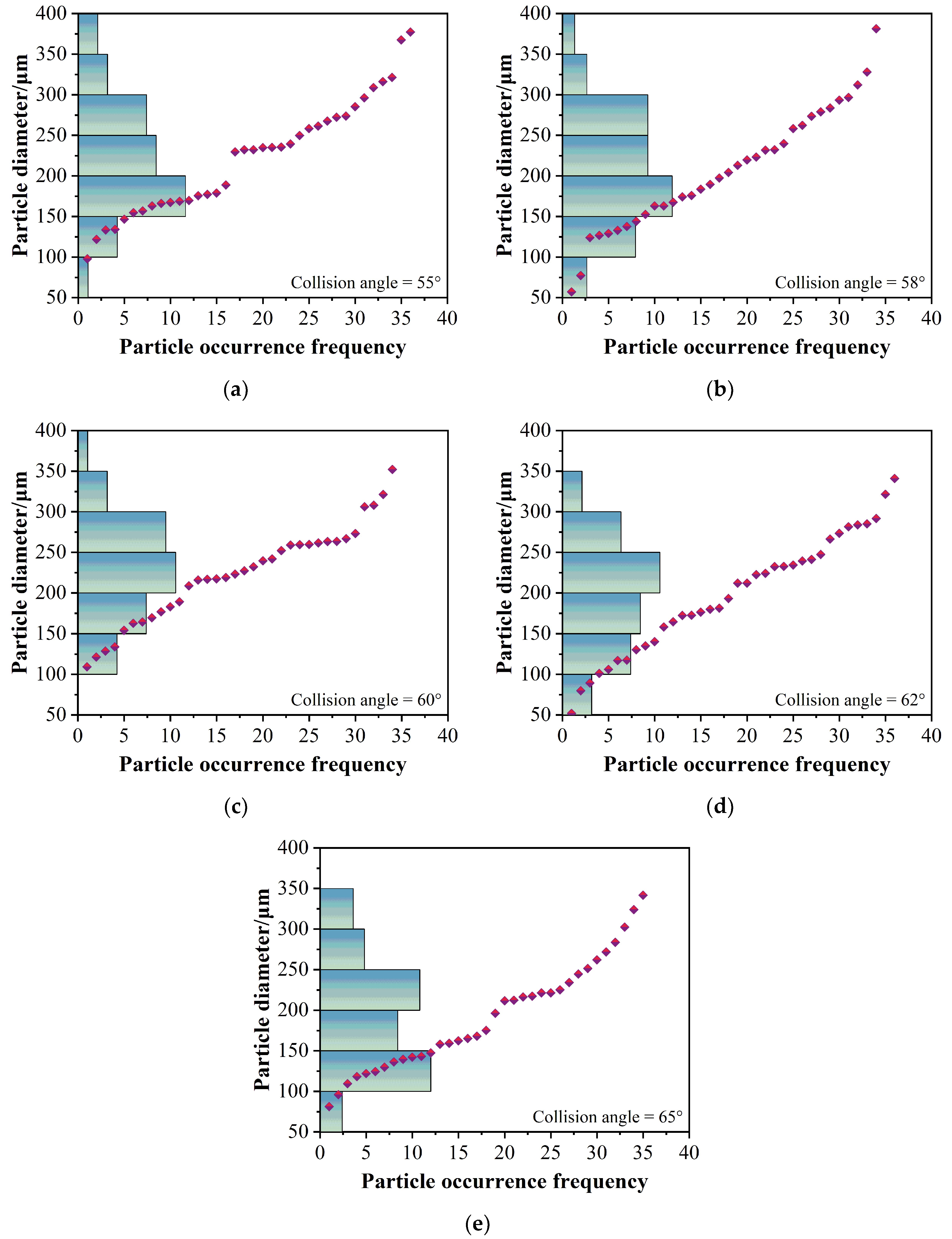
In order to analyze the spatial distribution of the atomization field at different collision angles, this study used the IPI method to measure the diameter of droplets in the atomization field at the same measurement point. Under an injection pressure of 0.8 MPa, the spatial distribution of droplets at the same measurement point of the atomization field, corresponding to different collision angles of 1mm diameter nozzles, is shown in Figure 15, in which the diamonds represent numbered droplets. Figure 15a–e shows the spatial distribution of the atomization field at collision angles of 55°, 58°, 60°, 62°, and 65°, respectively. It can be seen from Figure 15a that when the collision angle changed from 55° to 65°, the number of droplets with diameters of ~100 μm to 300 μm always accounted for more than 80%. As the angle increased gradually, the size of the atomized droplets decreased gradually, and the number of small atomized droplets increased. Based on the 60° collision angle, the number of large droplets over 300 μm produced by the atomization field with negative deviation was significantly higher than the number with positive deviation. Similarly, the number of small droplets below 100 μm produced by the atomization field with positive deviation was significantly higher than the number with negative deviation. The atomization field distribution was more uniform when the collision angle was between 58° and 62°, the particle size distribution was concentrated in 150 μm to 300 μm, and the peak position was very similar. This implied that when the collision angle changed within ±2° based on 60°, the spatial distribution of the droplets in the collision atomization field had no significant change and was relatively stable.
5. Conclusions
In order to explore the influence of the microdeviation of collision angles on the atomization effect, the influence of the collision angle varying at 60° on atomization characteristics was experimentally analyzed, based on IPI measurement technology. A self-designed replaceable transparent orifice atomizer wasused to analyze the internal flow and the atomization field.
The cavitation phenomenon of the internal flow field was analyzed by simulation and experiment, and the results of the internal flow field cavitation experiment were consistent with the simulation results. The critical pressure of the initial cavitation of 1mm diameter orifice was 0.25 MPa, and the critical pressure of the flip flow was 0.8 MPa.
The effect of injection pressure on the change in shape of the atomization field of the impingement nozzle was investigated experimentally. The relationship between the flow coefficient and the cavitation number of the inner flow field and the change curve of the volume flow rate of a single nozzle with the injection pressure was explored and analyzed. When the injection pressure increased to 0.35 MPa, the liquid film began to break, due to the cavitation in the inner flow field. When the injection pressure reached 0.85 MPa, the cavitation of the inner flow field entered a swirl state, and the atomization field almost reached a stable state. Due to the hydraulic flip, the flow coefficient changed greatly when the cavitation number was around 1.35, and the change curve of the volume flow with the injection pressure showed an opposite trend in the range of 0.38 MPa to 0.40 MPa.
The effects of the collision-angle deviation on the droplet size, the atomization cone angle, and spatial distribution of the atomization field were analyzed experimentally. The influence of spray pressure on the droplet size in the atomization field was also studied. The experimental results showed that the Sauter Mean Diameter (SMD) of the atomized droplets decreased with the increase in the injection pressure and tended toward a plateau value. As the collision angle increased, the SMD of the atomized droplets tended to decrease. Moreover, the larger the injection pressure, the smaller the SMD variation range that corresponded to different collision angles. The SMD values at spray pressures of 0.5 MPa and 0.8 MPa were very close. When the collision angle was 55° or 65°, the maximum difference in the SMD was approximately 100 μm and 40 μm, respectively. Under the same pressure, with the increase in the impact angle, the atomization cone angle showed an increasing trend, and the variation was relatively uniform. Under the four injection pressures, when the collision angle was in the range of 55° to 65°, the maximum increase in the atomization cone angle was 10.5°, 15.1°, 11.1°, and 10.6°, respectively. After reaching the hydraulic inversion state, the atomization cone angle was almost stable at a state slightly smaller angle than the corresponding collision angle. Taking 60° as the benchmark, when the collision angle changed within the range of ±2°, the particle size distribution was concentrated in the range of 150 μm to 300 μm, and the peak position was very similar.
Author Contributions
All authors contributed to the design of the experiment. Material preparation, data collection, and analysis were performed by Y.M. The measurement stack was designed by J.C. and J.T. The first draft of the manuscript was written by Y.M. All authors have read and agreed to the published version of the manuscript.
Funding
This work was supported by the Outstanding Youth Project of the Natural Science Foundation of Heilongjiang Province (Grant JQ2019E002).
Institutional Review Board Statement
Not applicable.
Informed Consent Statement
Not applicable.
Data Availability Statement
The authors will provide data and material upon reasonable request.
Acknowledgments
The authors would like to acknowledge the Outstanding Youth Project of the Natural Science Foundation of Heilongjiang Province (Grant JQ2019E002).
Conflicts of Interest
The authors declare that they have no conflict of interest or competing interest.
References
- Benjamin, M.A.; Jensen, R.J.; Arienti, M. Review of Atomization: Current Knowledge and Future Requirements for Propulsion Combustors. At. Sprays 2010, 20, 485–512. [Google Scholar]
- Umemura, A. Handbook of Atomization and Sprays Theory and Applications; Springer: New York, NY, USA, 2011. [Google Scholar]
- Yang, L.-J.; Zhao, F.; Fu, Q.-F.; Cui, K.-D. Liquid Sheet Formed by Impingement of Two Viscous Jets. J. Propuls. Power 2014, 30, 1016–1026. [Google Scholar]
- Zhao, F.; Yang, L.-J.; Mo, C.-J.; Li, X.-D. Characteristics of Sheet Formed by Collision of Two Elliptical Jets at Short Impact Distance. J. Fluids Eng. 2016, 138, 051201. [Google Scholar]
- Zhao, F.; Yang, L.-J.; Mo, C.-J.; Qin, L.-Z. Spray Characteristics of Unlike Impinging Jets. J. Propuls. Power 2017, 33, 1260–1271. [Google Scholar]
- Zhang, P.; Wang, B. Effects of elevated ambient pressure on the disintegration of impinged sheets. Phys. Fluids 2017, 29, 042102. [Google Scholar]
- Zhang, S.; Gou, W.; Wang, Y.; Zhang, J.; Zheng, Y. Direct numerical simulation of atomization by jet impact using moving particle semi-implicit method with GPU acceleration. Comput. Part. Mech. 2021, 9, 499–512. [Google Scholar]
- Ryan, H.M.; Anderson, W.E.; Pal, S.; Santoro, R.J. Atomization characteristics of impinging liquid jets. J. Propuls. Power 1995, 11, 135–145. [Google Scholar]
- Huang, J.C.P. The break-up of axisymmetric liquid sheets. J. Fluid Mech. 1970, 43, 305–319. [Google Scholar]
- Heidmann, M.F.; Priem, R.J.; Humphrey, J.C. A study of sprays formed by two impinging jets. Natl. Advis. Comm. Aeronaut. Tech. Note 1957, 3835, 1–34. [Google Scholar]
- Heidmann, M.F.; Humphrey, J.C. Fluctuations in a Spray Formed by Two Impinging Jets. J. Am. Rocket Soc. 1952, 22, 127–131. [Google Scholar]
- Santoro, R.J.; Anderson, W.E.; Ryan, I.H.M. Impact Wave-Based Model of Impinging Jet Atomization. At. Sprays 2006, 16, 791–806. [Google Scholar]
- Negeed, E.-S.R.; Hidaka, S.; Kohno, M.; Takata, Y. Experimental and analytical investigation of liquid sheet breakup characteristics. Int. J. Heat Fluid Flow 2011, 32, 95–106. [Google Scholar]
- Ma, D.-J.; Chen, X.-D.; Khare, P.; Yang, V. Atomization patterns and breakup characteristics of liquid sheets formed by two impinging jets. Aiaa J. 2011, 97, 1–14. [Google Scholar]
- Lai, W.-H.; Huang, W.; Jiang, T.-L. Characteristic Study on the Like-Doublet Impinging Jets Atomization. At. Sprays 1999, 9, 277–289. [Google Scholar]
- Xia, J.; Zhang, Q.; Wang, J.; He, Z.; Zhou, Q.; Zhou, D.; Qian, Y.; Ju, D.; Lu, X. Experimental study of the effect of various collision angles and critical conditions on marine engine’s twin-spray collision process. Int. J. Engine Res. 2022. [Google Scholar] [CrossRef]
- Wang, F.; Chen, J.; Zhang, T.; Guan, H.; Li, H. Experimental Study on Spray Characteristics of ADN/Water Based Gel Propellant with Impinging Jet Injectors. Propellants Explos. Pyrotech. 2020, 45, 1357–1365. [Google Scholar]
- Suñol, F.; González-Cinca, R. Low Weber number jet collision regimes in microgravity. Phys. Fluids 2017, 29, 112106. [Google Scholar]
- Cui, J.; Lai, H.; Li, J.; Ma, Y. Visualization of internal flow and the effect of orifice geometry on the characteristics of spray and flow field in pressure-swirl atomizers. Appl. Therm. Eng. 2017, 127, 812–822. [Google Scholar]
- Taylor, G. The Dynamics of Thin Sheets of Fluid. II. Waves on Fluid Sheets. Proc. R. Soc. Lond. 1959, 253, 296–312. [Google Scholar]
- Ma, Y.; Cui, J.; Wang, H.; Tan, J. Impacts of Micro-Deviations of Aperture on the Characteristics of Collision Atomization Field. Appl. Sci. 2022, 12, 4685. [Google Scholar]
- Zhang, Z.; Li, Y.; Wang, Z.; Hu, Q.; Wang, D. Experimental study on radial evolution of droplets in vertical gas-liquid two-phase annular flow. Int. J. Multiph. Flow 2020, 129, 103325. [Google Scholar]
- Kong, L.; Lan, T.; Chen, J.; Wang, K.; Sun, H. Breakup Processes and Droplet Characteristics of Liquid Jets Injected into Low-Speed Air Crossflow. Processes 2020, 8, 676. [Google Scholar]
- Bareiss, S.; Bork, B.; Bakić, S.; Tropea, C.; Irsig, R.; Tiggesbäumker, J.; Dreizler, A. Application of femtosecond lasers to the polarization ratio technique for droplet sizing. Meas. Sci. Technol. 2013, 24, 25203. [Google Scholar]
- Labs, J.E.; Parker, T.E. Multiple-scattering effects on infrared scattering measurements used to characterize droplet size and volume fraction distributions in diesel sprays. Appl. Opt. 2005, 44, 6049–6057. [Google Scholar] [PubMed]
- Darakis, E.; Khanam, T.; Rajendran, A.; Kariwala, V.; Naughton, T.J.; Asundi, A.K. Microparticle characterization using digital holography. Chem. Eng. Sci. 2010, 65, 1037–1044. [Google Scholar]
- Berg, M.J.; Videen, G. Digital holographic imaging of aerosol particles in flight. J. Quant. Spectrosc. Radiat. Transf. 2011, 112, 1776–1783. [Google Scholar]
- Mishra, Y.N.; Koegl, M.; Baderschneider, K.; Hofbeck, B.; Berrocal, E.; Conrad, C.; Will, S.; Zigan, L. 3D mapping of droplet Sauter mean diameter in sprays. Appl. Opt. 2019, 58, 3775–3783. [Google Scholar]
- Kapusta, U.J. LIF/Mie Droplet Sizing of Water Sprays from SCR System Injector using Structured Illumination. In Proceedings of the Ilass Europe. 28th European Conference on Liquid Atomization and Spray Systems, Valencia, Spain, 6–8 September 2017. [Google Scholar]
- König, G.; Anders, K.; Frohn, A. A new light-scattering technique to measure the diameter of periodically generated moving droplets. J. Aerosol Sci. 1986, 17, 157–167. [Google Scholar]
- Sun, J.; Zhang, H.; Fan, W.; Chen, S. Aspect ratios comparison of ellipsoidal particles through interferometric out-of-focus images. J. Opt. Soc. Am. A 2021, 38, 395–400. [Google Scholar]
- Zhang, H.; Li, Z.; Sun, J.; Fu, Y.; Jia, D.; Liu, T. Characterization of particle size and shape by an IPI system through deep learning. J. Quant. Spectrosc. Radiat. Transf. 2021, 268, 107642. [Google Scholar]
- Ma, Y.R.; Cui, J.; Tan, J. Interferometric laser imaging for droplet-size measurement in spray. Appl. Opt. 2022, 61, 5496. [Google Scholar] [CrossRef]
Figure 1.
Schematic diagram of the collision of two jets.

Figure 2.
Turbulence.
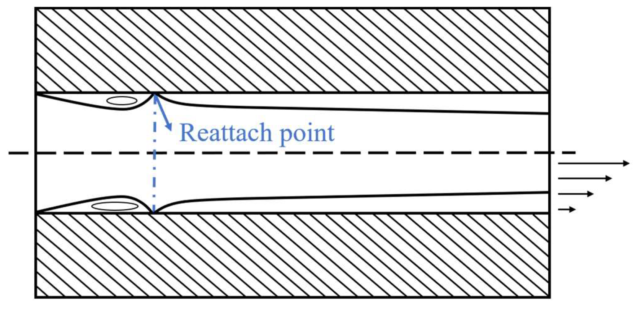
Figure 3.
Different cavitation states in internal flow field: (a) vacuolization; (b) supercavitation; (c) hydraulic flip; (d) partial reattachment flow.
Figure 3.
Different cavitation states in internal flow field: (a) vacuolization; (b) supercavitation; (c) hydraulic flip; (d) partial reattachment flow.

Figure 4.
Schematic diagram of the impact nozzle experimental system [21].
Figure 4.
Schematic diagram of the impact nozzle experimental system [21].

Figure 5.
Structure of single injector [21].
Figure 5.
Structure of single injector [21].
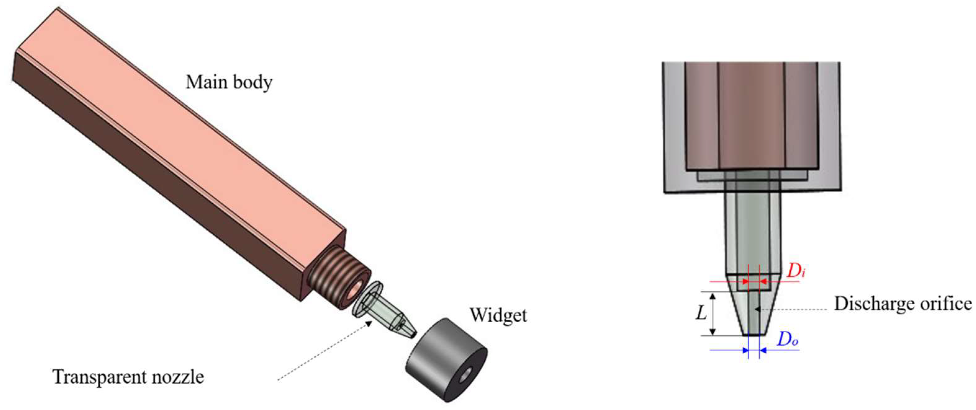
Figure 6.
Interference fringe image of 24 μm standard particle field.
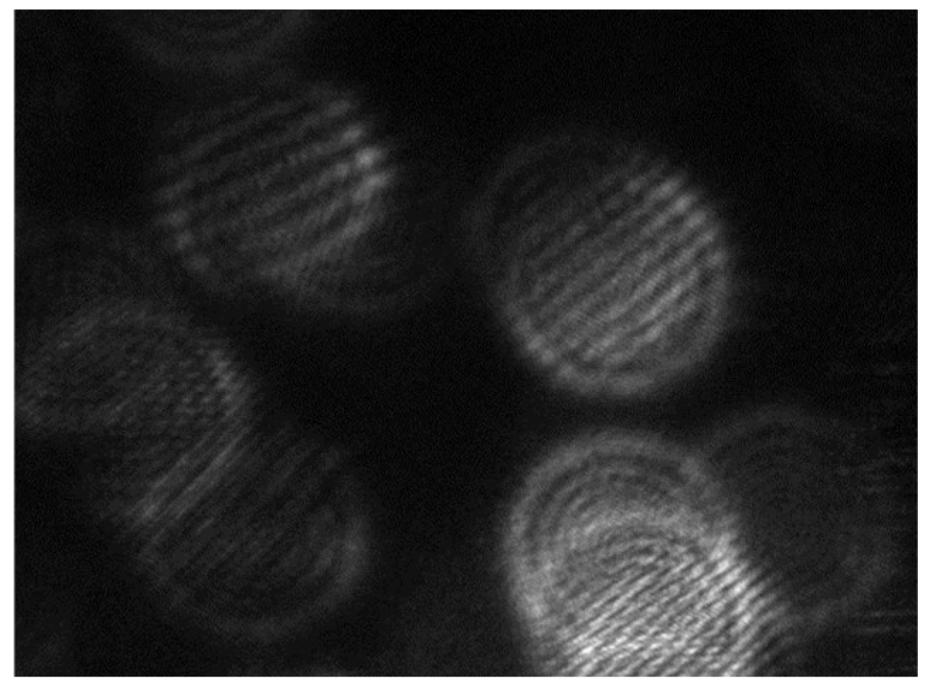
Figure 7.
The identification process and the results for the atomization cone angle: (a) original image; (b) measurement results for the atomization cone angle.
Figure 7.
The identification process and the results for the atomization cone angle: (a) original image; (b) measurement results for the atomization cone angle.

Figure 8.
Three-dimensional model and meshing of the nozzle.
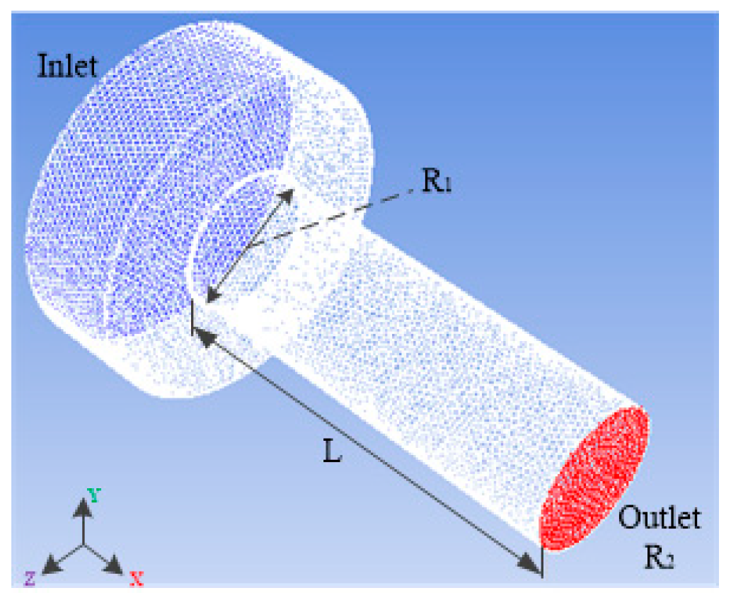
Figure 9.
Cavitation simulation and experimental comparison of 1 mm diameter orifice under different injection pressures: (a) 0.2 MPa; (b) 0.3 MPa; (c) 0.4 MPa; (d) 0.5 MPa; and (e) 0.8 MPa.
Figure 9.
Cavitation simulation and experimental comparison of 1 mm diameter orifice under different injection pressures: (a) 0.2 MPa; (b) 0.3 MPa; (c) 0.4 MPa; (d) 0.5 MPa; and (e) 0.8 MPa.
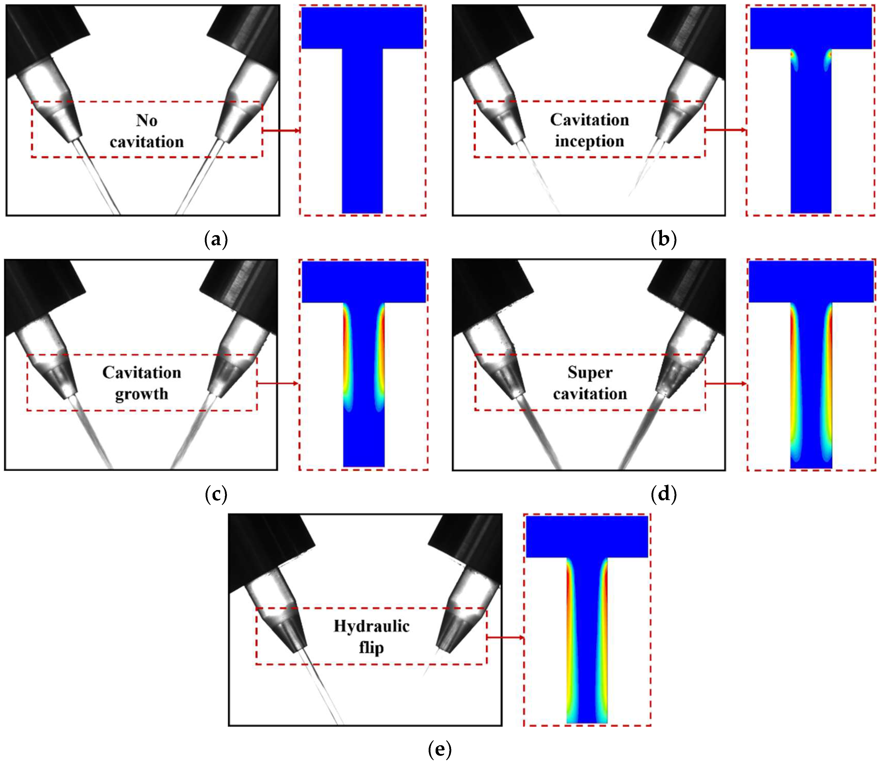
Figure 10.
Atomization field morphology of double jets with a 1 mm diameter nozzle at different impact angles under different injection pressures.
Figure 10.
Atomization field morphology of double jets with a 1 mm diameter nozzle at different impact angles under different injection pressures.

Figure 11.
Relationship between discharge coefficient and cavitation number of a single cylindrical nozzle.
Figure 11.
Relationship between discharge coefficient and cavitation number of a single cylindrical nozzle.

Figure 12.
Relationship between volume flow rate and injection pressure of single cylindrical nozzle.
Figure 12.
Relationship between volume flow rate and injection pressure of single cylindrical nozzle.
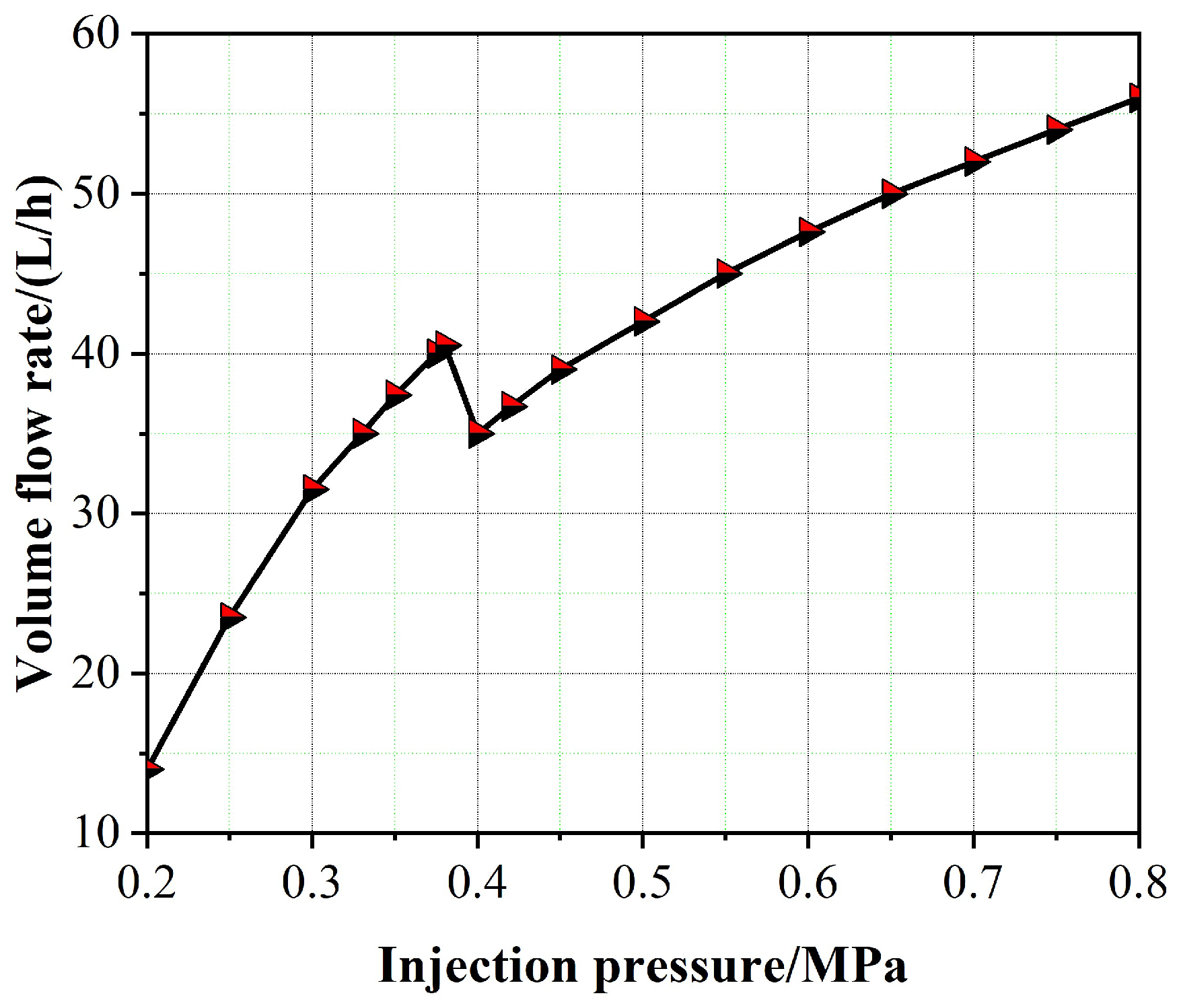
Figure 13.
SMD curves of spray droplets with the collision angle and spray pressure: (a) for the collision angle with small deviation change, the curve of injection pressure, and the droplet SMD; (b) the variation curves of the collision angle and the droplet SMD under different injection pressures.
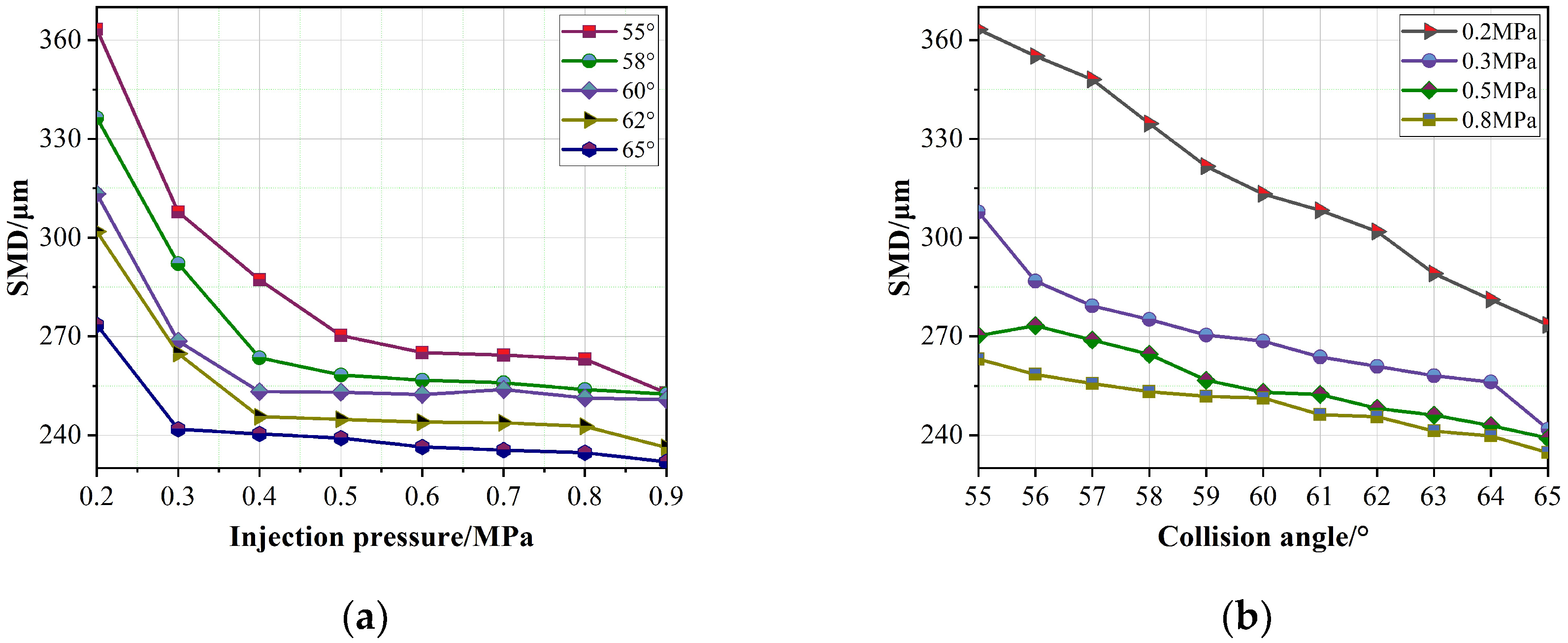
Figure 14.
Variation curve of atomization cone angle with the collision angle under different spray pressures.
Figure 14.
Variation curve of atomization cone angle with the collision angle under different spray pressures.

Figure 15.
Spatial distribution of droplets in atomization field at different collision angles under injection pressure of 0.8 MPa. (a) Collision angle = 55°; (b) Collision angle = 58°; (c) Collision angle = 60°; (d) Collision angle = 62°; (e) Collision angle = 65°.
Figure 15.
Spatial distribution of droplets in atomization field at different collision angles under injection pressure of 0.8 MPa. (a) Collision angle = 55°; (b) Collision angle = 58°; (c) Collision angle = 60°; (d) Collision angle = 62°; (e) Collision angle = 65°.
Publisher’s Note: MDPI stays neutral with regard to jurisdictional claims in published maps and institutional affiliations. |
© 2022 by the authors. Licensee MDPI, Basel, Switzerland. This article is an open access article distributed under the terms and conditions of the Creative Commons Attribution (CC BY) license (https://creativecommons.org/licenses/by/4.0/).
Share and Cite
MDPI and ACS Style
Ma, Y.; Cui, J.; Tan, J. Quantitative Expression of a Slight Deviation of the Impact Angle in a Collision Atomizer. Machines 2022, 10, 771. https://doi.org/10.3390/machines10090771
AMA Style
Ma Y, Cui J, Tan J. Quantitative Expression of a Slight Deviation of the Impact Angle in a Collision Atomizer. Machines. 2022; 10(9):771. https://doi.org/10.3390/machines10090771
Chicago/Turabian StyleMa, Yarui, Jiwen Cui, and Jiubin Tan. 2022. "Quantitative Expression of a Slight Deviation of the Impact Angle in a Collision Atomizer" Machines 10, no. 9: 771. https://doi.org/10.3390/machines10090771
Note that from the first issue of 2016, this journal uses article numbers instead of page numbers. See further details here.